

EZ Call a Matic User Manual

CallAMatic
User Manual

Document Revision No. 05
Firmware version 2.31, 3.01
CallAMatic User Manual
Fifth Edition December 2002
EZ Advantage Corp.
221, Broad Street,
Milford,
CT-06460
U.S.A.

For safe and reliable operation,
this unit must be grounded
properly. Failure to do so, will
void warranty
CallAMatic

CallAMatic

Table of Contents
Connection Diagram CallAMatic---------------------------------------------------------------------1
Product Overview -------------------------------------------------------------------------------------------3
System Features ---------------------------------------------------------------------------------------------4
Installation Guide--------------------------------------------------------------------------------------------5
Parameter Programming ----------------------------------------------------------------------------------7
Charge Setting Programs----------------------------------------------------------------------------------8
101 - Password Options------------------------------------------------------------------------------------9
102 - Configure Serial Ports-------------------------------------------------------------------------------9
103 - Configure SMDR ------------------------------------------------------------------------------------10
104 - Set Date and Time----------------------------------------------------------------------------------12
105 - Print On Fly-------------------------------------------------------------------------------------------12
106 - Raw Data Pass Thru --------------------------------------------------------------------------------13
107 - Grace Period -----------------------------------------------------------------------------------------13
108 - Print Non Call Record------------------------------------------------------------------------------14
109 - Auto Report Scheduling --------------------------------------------------------------------------14
110 - Do Not Print On Fly for following extensions -----------------------------------------------14
111 - Do Not Count Calls from these extensions --------------------------------------------------16
112 - DO Not Count Calls to these bands------------------------------------------------------------16
113 - Evening Rates ---------------------------------------------------------------------------------------16
114 - Weekend Rates--------------------------------------------------------------------------------------17
115 - Local/Local Long Distance Dialing Patterns: ------------------------------------------------17
116 - PBX Dial Out Strings -------------------------------------------------------------------------------19
117 - Default Credit Limit --------------------------------------------------------------------------------19
118 - Key Pad Entry Options ----------------------------------------------------------------------------19
119 - Administrative Extensions -----------------------------------------------------------------------20
120 - Do Not Print On Fly for following bands -----------------------------------------------------20
121 - Extension Pairing -----------------------------------------------------------------------------------20
122 - Beeper Control --------------------------------------------------------------------------------------21
123 - Report Pagination----------------------------------------------------------------------------------21
124 - PMS Integration-------------------------------------------------------------------------------------22
125 - PMS Formats-----------------------------------------------------------------------------------------22
126 - New Area Code Addition -------------------------------------------------------------------------25
127 - Name Of Property ----------------------------------------------------------------------------------25
128 - Caller-ID Disable Strings --------------------------------------------------------------------------26
129 Valid Extension List (for CALL-A-MATIC limited only) --------------------------------------26
130 PMS Test Program -----------------------------------------------------------------------------------26
201 to 630 Charge Setting Programs-----------------------------------------------------------------26
Supervisory Programs ------------------------------------------------------------------------------------29
Management Reports (MGMT REPORT key) --------------------------------------------------------30
Room Audit Reports (ROOM AUDIT key) ------------------------------------------------------------34
Toll Control Programming for MITEL PBXes---------------------------------------------------------37
Quick Set Up Guide----------------------------------------------------------------------------------------42
CALL-A-MATIC Software Version 3.00 ----------------------------------------------------------------45
Area Code List ----------------------------------------------------------------------------------------------48
Prefixed State Groups-------------------------------------------------------------------------------------50
International Country Code Bands--------------------------------------------------------------------51
CallAMatic

CallAMatic
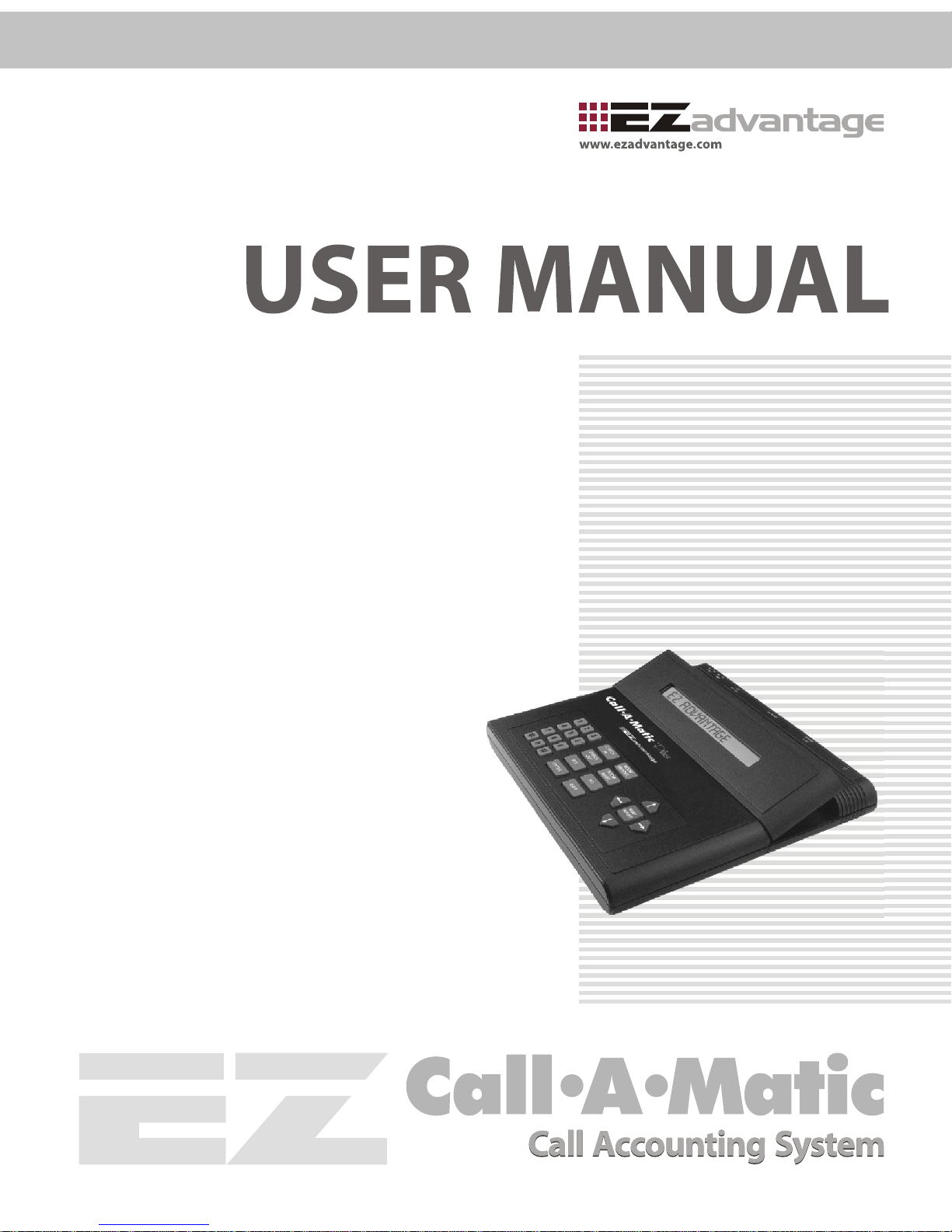
Connection Diagram
CallAMatic
Rear panel connector pin-outs
PBX-SMDR Connector Type female DB 25 pin
PMS-PC Connector Type male DB 9 pin
1 2 3 4 5
6 7 8 9
Signal ground
TX data outRx data in
Frame Ground
12345678910111213
1415161718192021222324
25
Frame Ground
TX data out
Rx data in
Signal ground
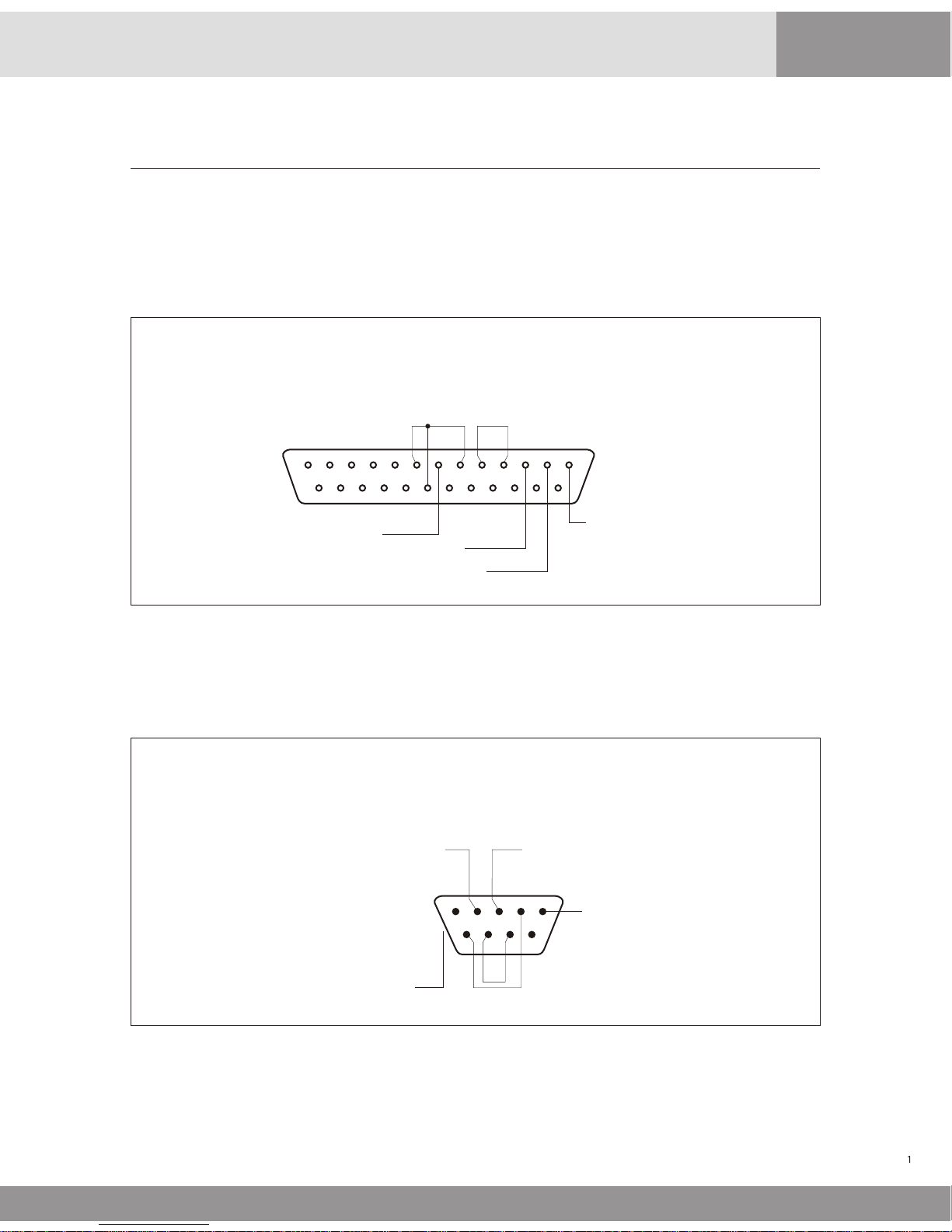
CallAMatic
Parallel Printer Connector Type female DB 25 pin
12345678910111213
1415161718192021222324
25
SX200 Toll Connector Type male DB 9 pin
1 2 3 4 5
6 7 8 9
Signal ground
TX data outRx data in
Frame Ground
Pin 1 - Strobe out
Pin 2 - Data out 1
Pin 3 - Data out 2
Pin 4 - Data out 3
Pin 5 - Data out 4
Pin 6 - Data out 5
Pin 7 - Data out 6
Pin 8 - Data out 7
Pin 9 - Data out 8
Pin 11 - BUSY input
Pin 12 - PE input
Pin 13 - SELECT input
Pin 14 - Printer RESET
Pin 18 to 25 - Signal ground
Pin 10, 14, 15, 17 - No connection
The Call-A-Matic is a stand-alone call accounting system designed specifically for the hospitality
industry. The unit is used to collect phone call data from a PBX (phone system) and then process
and store the calls that have been made and generate informative and useful reports in a variety
of formats.
The Call-A-Matic Plus is housed in a sleek ABS enclosure and the Call-A-Matic PMS Lite is housed in
a metal enclosure and is designed for desktop use.
This unit can store upto 2880 calls in its minimum configuration mode and the maximum storage
can go up to 15,168 calls. All the essential parameters are stored in a non-volatile memory.
The important features of the unit are given on the next page.
Specifications:
Power Input
9 to 12 volts AC or DC, 500 mA or 5.0 volts
DC, 1.5A depending on model
Power Consumption 3 watts max
Battery Back-up
Built in rechargeable type
Size
12” x 12” footprint
Input/Outpot ports
2-Serial Ports, 1-Parallel Printer Port
1-Modem Port-
Minimum Call Storage
2880 Calls
Maximum Storage
15,168 calls
Display
40 x 2 tiltable LCD Screen
Programming and Reports
Through 25 key keyboard
Parameter programming storage
Non-volatile storage in Flash ROM
Product Overview
CallAMatic

1. The Call-A-Matic plugs directly into the serial printer port of a PBX.
2. Fully programmable through a 25 key keypad with messages being displayed on a 40
X 2 line LCD display.
3. User may program the charges separately for each area code, a state, specific numbers
or type of numbers, each country, Operator or Information calls etc. May individually
mark-up all types of calls.
4. Charging of calls made from an extension may be excluded or included for mark-up
under user control.
5. Unit may be programmed to sound an alarm when calls are made to a particular
number or from an extension.
6. Password protection to insure against unauthorized deletion of calls records.
7. Two fully user configurable serial ports.
8. Can output the reports onto a serial printer and /or a parallel printer or an IBM PC
compatible system (PMS).
9. Call-A-Matic may be configured to interface with a wide variety of PMS.
10. User programmable SMDR format to allow interfacing with any phone system.
11. Informative reports guest check out reports, Audit reports, Room-wise reports,
extension-wise reports, and management reports at the touch of a key.
12. Memory protection circuitry insures against data loss. All essential parameters stored
in non-volatile memory.
13. This system may be integrated into a Hotel's billing system to provide phone call
details, automatically at checkout or shift end etc.
14. Credit limit may be set for each guest, for the total phone call charges, at check in time
and the buzzer will sound when that limit is crossed. Alternatively, the Call-A-Matic
can instruct the PBX to shut-off the room phone on violation of credit limit.
15. The Call-A-Matic can also restrict the use of each guest's phone for Local, Longdistance or International at check-in. (Toll Control). [for Plus and Limited models only]
16. The Call-A-Matic Plus may be programmed remotely.
System Features
CallAMatic

The CALL-A-MATIC System is simple and easy to use. You may start using the system without much
of a problem, as soon as it is unpacked.
The Call-A-Matic shipping carton must contain the following items :
The Call-A-Matic Unit
This User Manual
Wall Adapter
Parallel Printer Cable
Select a suitable location for the Call-A-Matic to be placed on the Front Desk of your hotel. A
suitable location should have a power socket close by and space for a parallel printer with
adequate clearance at the front and rear of the printer for loading and removing the paper in the
printer. The place selected should also be easily accessible for any service or maintenance work.
Plug in the wall power adapter into the power socket and insert the other end into the powerinput jack on the Call-A-Matic. Switch on the power to the unit.
The CALL-A-MATIC system has a Password protection feature and therefore you must use the
default password, before you proceed to program the unit.
(a) Power up the unit. The system should give a few beeps and display the start up message on
the display.
The normal sequence of the display will be
"MODEM CHECK”
“MODEM O.K.”
“DIAL TONE OK” or “NO DIAL TONE”
“PBX CONNECTED” or “PBX NOT CONNECTED”
'Installed memory....'
'CALL-A-MATIC....' version no., date of the software version.
Instead of the “MODEM OK” message, if the “MODEM NOT RESPONDING” message appears, it
means that there could be a system malfunction. You must inform your dealer or distributor,
from whom the unit was purchased,
After this, a screen appears, giving the PBX & printer status and the time, day & date. If the
unit is working properly, the time on the LCD will be displayed constantly. (If the date and
time are not correct, it may be set correctly later). If the PBX is not connected to the unit, a
beep will be sounded immediately on completion of the power on check and then again,
once every minute, till the serial cable from the PBX is plugged into the SMDR port.
(b) To get the system working, there are two absolutely essential requirements to be taken care
of - the SERIAL PORT CONFIGURATION and the SMDR CONFIGURATION must be done
correctly. Read the 'Configure Serial Port' and Configure SMDR' section in the 'Parameter
Programming' section before trying to get the system started. All the other programming
features may be tried out after doing this basic programming.
This procedure would be a lot easier and faster if you have connected a serial printer to the
serial port of the PBX and obtained the call records for a few hours, before trying to connect
the CALL-A-MATIC System.
If you have been able to get the serial port parameter details from the PBX manufacturer,
then you may proceed to program the serial ports of the CALL-A-MATIC system. If you have
obtained some call records from the PBX, it would be helpful in configuring the SMDR
format in the system.
Installation Guide
CallAMatic

(c) Type in the default password and enter the programming mode of the system. If the serial
port parameters of the PBX are known and if the PBX is listed in the predefined types under
program 103, then you may start using the system straight away.
If one or both of the above are unknown then proceed as follows.
(d) Read the section 'Raw Data pass through' in the programming section and set the system to
pass through the raw data read from the serial port to the parallel printer. Program 106
(page 13).
Now, set the serial port parameters for the PBX - you will have to try different combinations
one by one - and make a call from the PBX, so that the call record is put out by the PBX on its
serial port.
The most common baud rates are 300, 1200, 2400 and 9600 and usually 8-bit transmission
mode is used. So, start with these combinations and after every call is made, check whether
the printer prints out the call or not. You will have to continue with this trial and error
method till the correct combination is found.
(e) Once the serial port for the PBX interface is properly configured, print the Ruler lines on the
printer through Program 103 and then collect a few call records. Now, find out the starting
column numbers and field lengths for each field in the raw call record as received from the
PBX. Some samples records are given below: -
Date
05/10
05/10
05/10
Time
1.08 P
1.09 P
1.09 P
Duration
00:00:06
00:00:44
00:01:12
Ext
139
263
263
9
9
9
3892067
Number
1609386000
01191272481370
T092
T094
T098
TRK
AC.#
7099
7099
7099
Read the 'SMDR configuration' section and proceed to program the SMDR details accordingly.
After this is done, the details of the calls will start appearing on the LCD to indicate the proper
functioning of the unit in its very basic mode. By default, the system is programmed for MITEL
PBX with 1200 baud, 8 data, 1 stop, and no parity.
The next section describes each of the available programs in detail.
CallAMatic
Parameter Programming
101 - Passwords (to change/delete/set new passwords)
102 Configure serial ports (to configure the system's serial ports)
103 - Configures SMDR (to configure the SMDR of the PBX)
104 - Set time, date (to set the real time clock)
105 - Print on fly (to set print-on-fly options)
106 - Raw data pass through (to check the printer/serial port)
107 - Set grace time (to set grace time for call charging)
108 - Non call record options (to set options for non-call records)
109 - Auto report scheduling (to set auto night report timings)
110 - Do not fly print for extensions (to exclude some extensions from p-fly)
111 - Do not count call on extension (to exclude certain extensions)
112 - Do not count calls on bands (to exclude certain bands)
113 - Evening Rates (set discounted evening rate timings)
114 - Weekend Rates (set discounted weekend rate timings)
115 - Local Calling (set Local / local LD dialing options)
116 Toll Control (dial out required through test line)
117 - Default Credit Limit (set default credit limit)
118 Keypad options (keypad time out, typing rate)
119 - Administrative extensions (No toll control/surcharge extensions)
120 - Do not print on fly bands (exclude some bands for printing on fly)
121 Extension pairing (pair two extensions in a room)
122 - Beeper control (Beeper on/off )
123 - Page control options (reports on top-of-page etc.)
125 - PMS formats (select PMS type)
126 - New AREA CODE additions (Add new area codes)
127 Property name (enter name of property)
128 Caller Id strings (digits to strip for caller-id disable)
129 Valid extension list (for Call-a-Matic Limited only)
130 PMS test program (to send dummy PMS records to PMS)
Program No.
Program description
CallAMatic
To enter into the programming mode, press Þ key first and then as prompted by the message on
the display press ENTER To abort, press EXIT
When you press ENTER the message "Enter Password:" is displayed. Enter your password here to
gain access to the programming mode. If an invalid password is entered, the system prompts the
message ' illegal password ' and returns to normal mode of operation.
Users of 4 digit passwords are not allowed access to parameter programming. Once a valid
password is entered, the message "Enter Program No.:" is displayed.
Once a valid program number has been entered, the message prompts for that program are
displayed. A '+' sign in the top right hand corner means help is available for this program. Press
the BLUE key to view the Help messages. If an invalid program number is entered, the error
message “No such program number” is displayed on the screen. Press any key to erase the message.
The programs available are:

The program numbers from 201 to 630 are all charge-setting programs. These program numbers
are also referred to as band numbers in all reports.
201 - Local calls
202 - Local long distance
203 - 1+ 10 digit calls (Local) (Local, enter area codes)
204 - Common charges for interstate calls (1+10 digit LD calls)
205 - Common charges for all INTL Calls 011 calls
206 - Info calls 1411,411,5551212, 1555 1212
207 - Other 1 + 10 digits not listed elsewhere
208 - Undefined 011 international calls
209 - 1-XXX info calls 1 XXX 555 1212
210 - 1-700 calls
211 - 1-800 calls 1-800, 1-888, 1-877 calls
212 - 1-900 calls
213 - 976 calls
214 - 710 calls
215 - 0+ calls
216 - International credit calls 01 XXX XXX XXXXXXX
301 - 362 State lists with area codes for USA & Canada
401 - 421 prefixed state groups.
500 - 530 prefixed international country code group
601 - 608 user programmable bands for area codes
609 - 616 user programmable bands for exchange
617 - 621 user programmable bands for International codes
622 - 625 user programmable bands for particular #'s
626 - 630 user programmable bands for alarm #'s, area codes and exchanges.
Charge Setting Programs
Supervisory Programs
800 - Parameter dump
999 - Clear all memory and load default parameters
998 - Load all default charges
996 - Clear property name
995 - Clear Exception report strings
992 - Delete all entries for 110-112,115,119,120,121,126,128,6xx programs
991 - Delete all calls and room numbers
990 - Delete all calls and room numbers, clear user defined entries, load default charges, load
default SMDR, serial port parameters, grace periods
980 - Save program parameters in non-volatile memory
970 - Restore program parameters from non-volatile memory
CallAMatic

101 - Password options
The passwords may be of 4, 5, or 6 digits. There is a single 6-digit password programmed into the
hardware and cannot be changed. This password would be used by the maintenance personnel and
is known only to the manufacturer's representatives.
There is 1 default password of 5 digits, which is programmed into the unit when shipped from factory.
A maximum of 2 passwords of 5 digits and 3 passwords of 4 digits may be programmed in the unit. If
you try to enter more passwords than the maximum permitted, an error message will be displayed.
The 5 digit passwords allow access to all programs. Access to programming mode is denied for 4 digit
password users.
Under this program, the user has the following options:
1. Change existing password
2. Define new password
3. Delete existing password
4. View existing password (only with 6 digit master password)
The 5 digit and 4 digit passwords may be changed by the user under this program. The system
prompts the message -
Current Password : (enter the password that needs to be changed)
New Password : (enter the new password)
You may delete only one password at a time. The unit will not allow you to delete the last remaining 5digit password.
102 - Configure Serial Ports
The two serial ports of the system may be configured under this program.
When you go into this program, the unit prompts with the message:
“Configure PBX/SMDR port ? (yes/no) :”
If you press the YES key, the unit will show the current settings for the SMDR serial port.
The default values shown would be “ 1200, 8 bits, No-parity, 1-stop”
Use the left and right arrow keys to move to the next or previous parameter on the line. Pressing
the NO key will take you through the available options for the current parameter. To select a
different baud rate, position the blinking cursor on the baud rate, press the NO key repeatedly till
the desired baud rate value is displayed on the screen and then press the YES key. Repeat this
procedure till all the parameters are properly selected as desired. Pressing the ENTER key
anywhere will take you to the next screen. EXIT key will take you back to the main menu of “Enter
program Number”
Repeat the above procedure for the other serial port when the unit prompts with the message:
“Configure PMS/PC port ? (yes/no) :”
At this point, the NO key will take you back to the main menu. The YES key will show the currently
programmed values for the second serial port.
Note: The PMS/PC port configuration screen will not pop up if the PBX type
selected under program # 116 is SX200 MITEL LITE or ATLAS. The serial port
parameters, in this case, must be defined under program # 116.
CallAMatic

The available options for all the individual parameters are:
Baud Rate
Data bits
Stop bit
Parity
19200
9600
4800
2400
1200
600
300
7 data bits
8 data bits
1 stop bits
2 data bits
No parity
Odd parity
Even parity
103 - Configure SMDR
The Serial Module Data Record received from the PBX must be decoded properly by the system and
for this, it is essential to define the SMDR of the PBX correctly.
The SMDR definition for the following PBXs are predefined in the unit:
MITEL
JISTEL
CARDINAL
COMDIAL
TOSHIBA
FUJITSU
AT&T
NORTEL
NEC
ATLAS
TRANSTEL
USER DEFINED
If MITEL PBX is selected, one more option is prompted.
MITEL Answer detection enabled ? YES/NO
In some locations, the TELCO provides a positive identification of a phone call having actually been
put through. If such a facility is available and the MITEL PBX is appropriately programmed, it
provides this information in the SMDR as an ANSWER DETECTION character. In such cases, the call
duration will always be the actual duration for which the call was made. Hence, grace period
method of charging may be avoided for these calls.
However, even if the Answer Detection is enabled, the grace period method is applied for all calls,
which do not have the “Answer detection” character ion the SMDR. This is done, because, typically
the Answer detection is available only on T1 lines which are normally used for Long distance and
International calls only. Hence, Toll free and Local calls etc. do not have Answer Detection facility.
When the USER DEFINED option is selected, you have the option of enabling or disabling the
RULER LINE in the next screen. If the ruler line is enabled, the unit prints a ruler line on the printer
and the incoming call record is printed below it. If the RULER LINE is enabled, the unit will not
process the call, but will print it out directly onto the printer as received from the PBX, even while
the user is still in the programming mode.
CallAMatic

Hence, if the SMDR pattern is not known or does not fit the pre-defined PBX types, enable the ruler line
and make a few calls. From the print out, determine the starting columns and field lengths of the
different fields in the call record and enter them in the user defined SMDR pattern.
If USER DEFINED option is selected, the details must be entered (starting column and field lengths).
Once the User Defined type has been defined, the entered values will be prompted the next time. If
any of the above fields are to be ignored, enter 0000 for that field. The fields that need to be defined
are:
DATE
TIME
DURATION
EXTENSION
CALLED NO
TRUNK ID
AC.CODE
DURATION TYPE hh:mm / hh:mm:ss
mmm.m
mmmss
sssss
Hmmts
Start / End time
For each of the above fields, the column numbers and field lengths of all the fields of the call
record are to be entered. The System prompts the field name and expects a 4-digit number, giving
the starting column number of the field in the call record (a 2-digit number), followed by the field
length (a 2 digit number) e.g. 2805 etc.
The call records stored in the memory after processing the incoming records have a predefined
format. The length for each of the fields in the processed record has a maximum limit and hence,
even if you define a larger field length in the SMDR format, it would be truncated. However, if you
define a smaller field length, only that many digits would be taken.
For example, the 'Extn' field has a 4 digit maximum limit and hence, even if you define a 5-digit
extension field, only four digits would be taken starting from the column number specified by you.
However, if you define a smaller field length, only that many digits would be taken.
The DURATION, EXTENSION and CALLED NUMBER fields in the incoming SMDR are validated for
correctness in all incoming call records. If any of these fields contain invalid characters, the record
would be treated as a NON-CALL record.
The DATE and TIME fields are also validated. However, if either one or both of them are invalid, the
current date and time from the real-time clock in the unit is automatically inserted into the call
record.
No validation is done for the TRUNK and AC.CODE fields.
Once the USER DEFINED SMDR is defined fully, you have the option of disabling the RULER LINE
printing. If this is not disabled, the unit will continue to be in a raw data pass through mode, where
it will print the ruler line and then the call record as received from the PBX.
While processing the calls, the Call-A-Matic automatically takes care of the following :
ALTERNATE CARRIER CALLS 10xxx or 101xxxx
RIGHT-JUSTIFIED CALLED NUMBERS
DASHES SEPARATING THE AREACODE AND EXCHANGES
CallAMatic

If the called number has been dialed with an alternate carrier access code prefixed to the actual
called number, the Call-A-Matic automatically identifies and strips off the excess digits. However, in
the reports and the print on fly records, such calls can be easily detected since a “+” is prefixed in
front of the called number field of the output record.
If the called number is right justified in the incoming call record, the Call-A-Matic automatically
adjusts the digits properly. Hence, while defining the SMDR fields, the starting column must be
defined in such a way that the leading digits of even the longest called number including the
Alternate carrier access digits - are not missed out.
104 - Set Date and Time
The time and date of the 'real time clock' in the system may be set as per the actual time. Use the
right and left arrow keys to go from one field to the next or previous one. Use the NO key to scroll
through the month and day-of-week. The date and time has to be entered in by using the digit
keys. The YES key would also take you to the next field. Enter will take you to the next screen.
The time received from the PBX in the call record is used for checking whether the call was during
Evening or Weekend rate period.
105 - Print On Fly
As soon as a call record is received, it is validated & formatted as per the standard format of the
system, the type of call is identified, the charges calculated and stored in memory. If this formatted
record is to be immediately printed out every time after the record is received, then enable the
'print on fly' option. By default, this option is enabled. The options available are -
Print-on-fly without header (default)
Print-on-fly with Header
Print-on-fly Disabled
The NO key and the left / right arrow keys toggle through the available options. Press YES or ENTER
to go to the next screen.
Store no charge calls ENABLED (Default) DISABLED
Additional blank lines between print-on-fly records? (0 to 9)
If you set 0 as the number of additional lines between print on fly records, then each
of these records would be printed on consecutive lines.
Printer set up: Options available are
PARALLEL PRINTER ONLY (default)
SERIAL PRINTER ONLY
SERIAL = PFLY ONLY, P'LLEL = ALL DATA
SERIAL = PFLY+NON CALLS, P'LLEL=REPORTS
ALL DATA ON SERIAL & P'LLEL PRINTERS
The serial printer is connected to the port marked SERIAL/PMS PC at the back of the unit. If both
serial and parallel printers are being used and you want to separate type of information to appear
on the two printers, choose the third or the fourth option given above. The fifth option is usually
used for troubleshooting.
If the PMS option is enabled, this `printer set up' screen will not pop-up.
CallAMatic
 Loading...