

Page 1

USER MANUAL
“SP” SERIES
EYS SCREW PRESS SEPERATORS
SP400
SP600
SP800
SP600HD
SP800HD
JAN 2012
Page 2

Congratulations on your purchase of the EYS Screw-Press Separator!
We are glad that you chose EYS separator for your solid-liquid separation solutions and are confident that
you will be more than satisfied with your purchase.
This manual is intended to provide basic information about the operation of the EYS Separator, and to point
out to main areas of consideration while operating and maintaining the machine. Please read this manual
carefully before operating the machinery, and keep it in an easily accessible place for future reference. If
any of your questions or concerns are not covered in this manual, please contact the respective dealer who
had installed the machinery. Your dealer’s contact information is:
If you are not able to reach your dealer and in need of immediate support, then please contact EYS directly
at:
EYS Metal Sanayi ve Ticaret Ltd. Şti.
ASTIM Org. San. Bol. Hurriyet Mah. Havaalanı Bul. No:233, Tepecik/AYDIN - 09100 TURKEY
Tel: +90 (256) 231 05 98
231 11 38
231 05 76
Apart from providing technical and operational instructions, this manual also includes certain safety
warnings that must be followed by the user. The safety instructions and warnings listed in this
manual are by no means a complete list of all safety concerns associated with operating the
machine. Users must apply common sense and abide by the general safety guidelines that govern
operating of machinery.
Contents of this manual refer to the latest product models currently in production at the time of
preparation of the document. EYS reserves the right to make changes in the product design at any
time.
Carefully following the instructions set forth in this manual are essential for maintaining operator
safety as well as the longevity and efficiency of the machinery. Dealers must provide a copy of this
manual to the customer along with the purchased product.
Page 3

“SP SERIES” USER MANUAL
Page 3 / 34
Please make sure that the operator in charge of operating and/or maintaining this product has full
access to this manual and that he/she has read it entirely prior to running or servicing the machine.
Also please record your product model number and serial number from the machine’s info-tag to the
following section. These info will be necessary and useful when ordering replacement parts in the
future.
Congratulations again on your purchase of the EYS Screw Press Separator!
PRODUCT INFO
Product : Screw Press Separator
Model : SP400 SP600 SP800 SP600HD SP800HD
Serial Number :
Dealer :
Adress :
Tel :
Fax :
Installation Date :
Manufacturer : EYS METAL SANAYİ VE TİCARET LTD. ŞTİ.
ASTİM ORGANİZE SANAYİ BÖLGESİ, HÜRRİYET MAHALLESİ, HAVAALANI BULVARI
NO:233, TEPECİK, AYDIN, TÜRKİYE
TEL: +90 (256) 231 05 98, 231 11 38, 231 05 76, 231 05 77
FAX: +90 (256) 231 11 01
e-mail: [email protected]
internet: www.e-y-s.com
Page 4
“SP SERIES” USER MANUAL
Page 4 / 34
HAND-OVER FORM (TO BE SIGNED OFF BETWEEN THE DEALER AND THE CUSTOMER)
Product : SCREW PRESS SEPARATOR
Model : SP400 SP600 SP800 SP600HD SP800HD
Serial Number :
Dealer :
Adress :
Tel :
Fax :
Installation Date :
Manufacturer : EYS METAL SANAYİ VE TİCARET LTD. ŞTİ.
ASTİM ORGANİZE SANAYİ BÖLGESİ, HÜRRİYET MAHALLESİ, HAVAALANI BULVARI
NO:233, TEPECİK, AYDIN, TÜRKİYE
TEL: +90 (256) 231 05 98, 231 11 38, 231 05 76, 231 05 77
FAX: +90 (256) 231 11 01
e-mail: [email protected]
internet: www.e-y-s.com
This form confirms that the product installation and start-up has been completed
successfully. Basic training has been provided and this manual has been handed over to
the responsible personnel below.
Responsible person on behalf of
the dealer/distributor
(date and sign)
Responsible person on behalf of
the customer
(date and sign; please print name)
ATENTION !
Manufacturer’s warranty is not valid unless this form is signed and
dated upon installation!
Page 5

“SP SERIES” USER MANUAL
Page 5 / 34
INTRODUCTION
Signs And Definitions
The CE sign designating
conformance with the relavant specific EC
Directives as well as the General Machinery Directive, has been
marked on the product by the manufacturer.
WARNING!
This warning box is used to highlight safety related precautions
throughout the document. Remember that there is risk of personal
injury with every “warning” sign topic and it is of utmost importance
to understand and follow the contained instructions carefully.
ATTENTION !
Failure to follow instructions can result in damage to a part or the
whole of the machine, possibly putting the machine out of
commission.
NOTE !
It is especially important to understand and implement the
instructions highlighted therein for the successful long-term
operation of the machine.
Qualified Operators should be properly trained in their assigned area of responsibility, be
knowledgable about general machinery handling precautions and related hazards/risks, capable of
foreseeing and preventing potential damages to the machine before they happen, and be able to apply
necessary first-aid practices as necessary.
Operational Responsibility
Responsibility of operating the machine in accordance with its intended purposes lies with the
customer. The manufacturer is not in anyway responsible for any damages that may be caused by
inappropriate handling of the waste streams resulting form the operation of the product. Likewise, the
manufacturer can not be held responsible for any damages resulting from the use of un-approved
and/or non-original spare parts on the machine.
Second-hand Ownership
In the case of transfer of ownership of the product to a new customer, the original owner is responsible
for handing over this user-manual to the new owner. New owner must be informed and trained about
the basic operation of the product accordingly.
Operational Liability
The entire liability of operating the product properly lies with the customer. The customer is
responsible for making sure that the product is used in accordance with the guidelines set forth in this
document, plus other general machinery operating rules that may not be covered here but are
expected to be known by any machinery operator. The maximum liability of the manufacturer in any
event can not exceed the monetary value of the product itself.
Page 6

“SP SERIES” USER MANUAL
Page 6 / 34
CONTENTS:
1 SAFETY INSTRUCTIONS………………………………………………………………………………………………… 7
2 GENERAL INSTRUCTIONS……………………………………………………………………………………..……… 8
2.1 Working with slurry………………………………………………………………………………………...….…… 8
2.2 Proper operation…………………………………………………………………………………………..….…….. 8
3 OPERATION PRINCIPLE…………………………………………………………………………………….……….…. 8
4 INSTALLATION & START-UP....………………………………………………………………………..………….… 9
4.1 Delivery ………...............…..………………………………………………………………………………………. 9
4.2 Handling.......………………………………………………………………………………………………..……….... 9
4.3 Typical installation........…………………………………………………………………………………………... 10
4.4 Setup & installation…………………………………………..…………………………………………………….. 10
5 PRE-START-UP CHECKS............................................……………………………………………………… 12
6 START UP…………......................……………………………………………………………………………………… 12
6.1 Counter-pressure on discharge doors…..…………………………………………………………………. 12
6.2 Establishing the solid plug…….....……………………………………………………………………………… 12
6.3 Plug adjustment………………………………………………………………………………………………………. 13
6.4 Other points of consideration...............…………………………………………………………………… 14
7 TROUBLESHOOTING..............................................................…………...………………………….. 16
8 STOPPING THE SEPARATOR…..………………………………………………………………..………………….. 19
9 LONG TERM STORAGE OF THE SEPARATOR…......………………………………………………………… 19
10 CHECKING THE SCREEN AND THE SCREEN GUIDE-RAILS…….…………………..…………………… 19
11 CHECKING THE AUGER……….....……………………………………………………………………………………. 20
12 ACCEPTABLE WEAR AND LIMIT TOLERANCES……………………………………………...……………… 21
13 DISASSEMBLY AND ASSEMBLY…….….…………………………………………………………………………… 22
13.1 Disassembly…..………………………………………………………………………………………………………… 22
13.2 Assembly…..…………………………………………………………………………………………………………….. 23
14 GENERAL MAINTENANCE…………………………………………………………………………………………….. 24
15 STORAGE…….......………………………………..……………………………………………………………………….. 25
16 TECHNICAL SPECIFICATIONS……………....…………..………………………………………………………….. 25
16.1 Technical specifications of the separator……...………………………………………………………… 25
16.2 Machine tags……...........…………………………………………………………………………………………… 27
16.3 Warning signs……....………………………………………………………………………………………………… 27
17 ELECTRIC CONTROL PANEL………......……………………………………………………………..…………….. 28
17.1 Wiring diagrams………………………………………………………………………………………..……………. 28
17.2 Reverse-run of auger at start-up…….......................................……………….......…………… 28
18 SPARE PARTS LIST………......………………………………………………………………………………………….. 29
19 MANUFACTURER’S WARRANTY …....…………....……………………………………………………………. 29
20 EC DECLARATION OF CONFORMITY ………...…….…………………………………………………………… 30
EXHIBITS (Spare Parts List; Wiring Diagrams)………............................................…………… 31-
Page 7

“SP SERIES” USER MANUAL
Page 7 / 34
1 SAFETY INSTRUCTIONS
Check conformance with safety instructions prior to each start-up!
1. In addition to the specific instructions contained in this document, general machinery operating
rules and precautions must be followed!
2. Safety related signs are marked on the product as necessary. These signs and stickers are
important for personal safety, so do not remove them!
3. Do not operate the machine before replacing/installing all safety and protection related
parts/covers!
4. Make sure you understand the general functioning principle of the machine before operation!
5. Put on relatively snug operational outfit when operating the machine. Loose outfits and long
sleeves can get caught by the moving parts during operation and servicing.
6. Slurry can emit flammable gases under certain conditions; so avoid smoking or carrying open fire
near the machine!
7. Machine should be installed at a properly ventilated area. Avoid spending long periods of time in
poorly ventilated areas around the slurry!
Maintenance
1. Never perform any maintenance, service or cleaning before fully stopping the machine and the
other system components.
2. Always check and verify that the bolts/nuts on the machine are securely tightened.
3. Always wear work gloves when handling sharp and metal objects during maintenace.
4. Always observe local regulations when disposing of lubricants/grease, etc.
5. Never work on the control panel and/or electrical connections without fully cutting off the power
first.
6. Only manufacturer approved spare parts must be used for repairs and replacements.
2 GENERAL INSTRUCTIONS
Page 8
“SP SERIES” USER MANUAL
Page 8 / 34
2.1 Working with slurry
WARNING !
Slurry can emit flammable and nauseus gase
s
. Always ensure that
there is proper ventilation in the operation area.
2.2 Proper Usage
EYS screw press separator is designed to separate solid and liquid phases of fiber-rich waste materials.
The waste should be free of sand, as well as other foreign objects such as metal, glass, wood, etc. that
have the potential of damaging the internal parts of the separator.
3 OPERATION PRINCIPLE
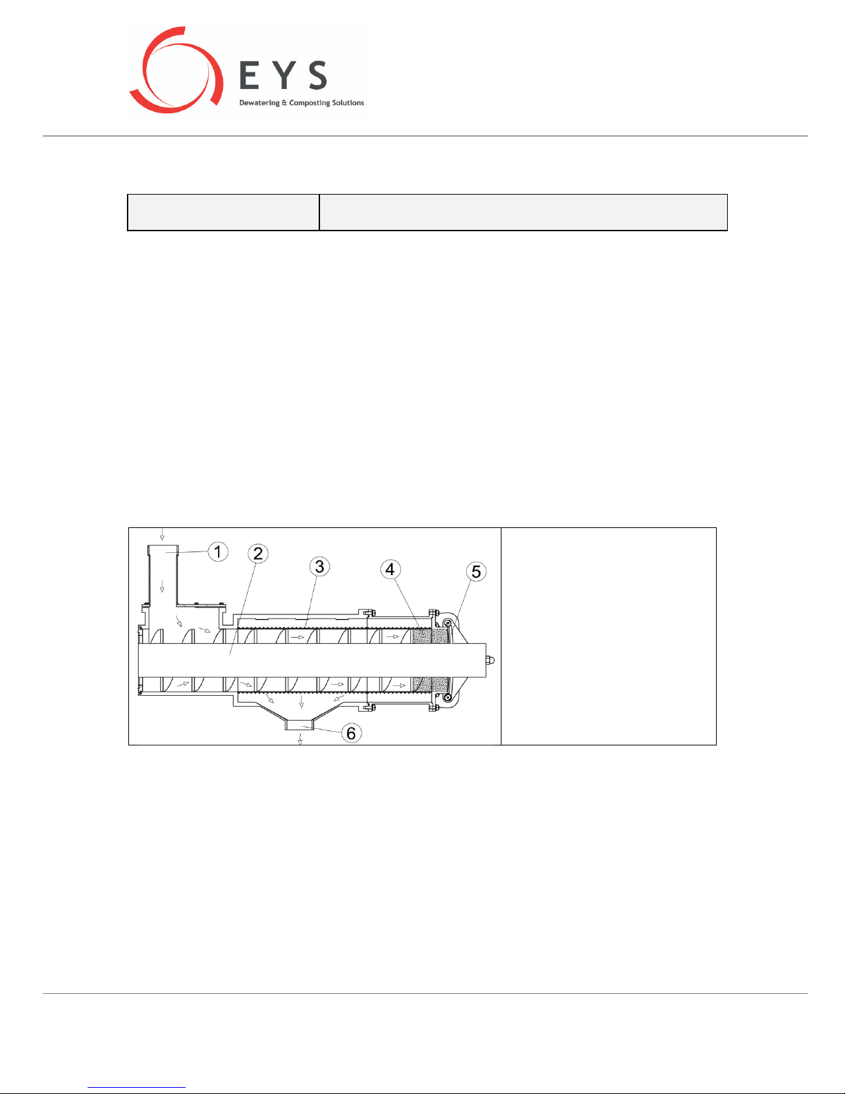
Slurry can be fed into the EYS Separator either by a pump or gravimetrically through a hopper at the
inlet. The auger inside the separator moves the slurry forward from the inlet section towards the solids
discharge outlet. During this travel of the slurry, the cylindrical screen around the auger continously
dewaters the liquid fraction of the slurry and channels it out through the liquid discharge outlet.
Meanwhile the dewatered solids form into a firm plug as they get closer to the discharge area. At the
solids discharge outlet, there are two hinged doors that apply constant pressure to the solid plug by
means of counterweights attached to the arms that regulate the angle of these doors. As the auger
furthers the solid plug forward, the plug overcomes the backpressure applied by the discharge doors
and exits the machine from the discharge outlet.
1. Slurry inlet
2. Auger
3. Screen
4. Solid plug
5. Separated solids discharge
6. Separated liquid discharge
Operational efficiency of the separator (throughput and dryness of solids) is greatly affected by the
slurry consistency. Therefore performance results may vary depending on what kind of slurry is being
dewatered. Following principles should be kept in mind when optimizing performance.
• Separation efficiency is typically increased when a larger screen slot-size is used. This in turn
will result in more solid particles to escape into the separated liquid phase.
• Smaller screen slot-size typically results in less solids percentage in the separated liquid phase.
However throuhput will be lower with smaller screen slot-sizes.
• Moisture content of the separated solids is typically reduced with increased back-pressure at
the discharge doors.
4 INSTALLATION AND START-UP
Page 9

“SP SERIES” USER MANUAL
Page 9 / 34
4.1 Delivery
EYS Seperator is delivered fully assembled; in a secure crate. Net weight of each model is as follows.
SP400
SP600
SP800
SP600HD
SP800HD
Net Weight [kg]
450 700 850 950 1100
4.2 Handling
The machine must be handled and lifted with a safe and proper method as required by the specific
circumstances of the installation location. A suitable crane and/or forklift must be utilized. Please
refer to the above figure for proper lifting arrangements by forklift or crane.
WARNING !
A properly chosen forklift can be used for transferring and/or lifting of the
separator to short distances or heights. Use the specifically designed forklift
openings on the legs of the separator. Make sure that the forks of the forklift
are fully through these openings on both legs. A crane should be employed
when lifting the separator to higher locations (such as while installing on an
elevated platform). When lifting with a crane, use two slings of 3m length and
1ton lifting capacity each, together with proper shackles. Apply the slings as
shown in the above figure. Never lift with chain or steel cable. These lifting
procedures must be followed not only for initial installation but for subsequent
liftings also, whenever necessary.
4.3 Typical Installation
Page 10
“SP SERIES” USER MANUAL
Page 10 / 34
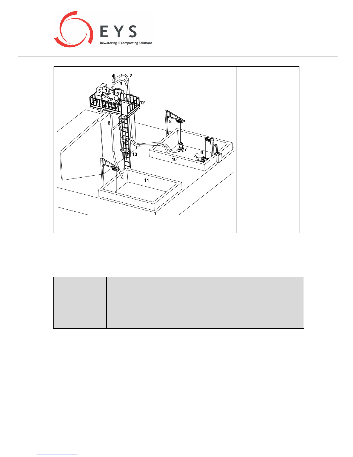
1. Separator
2. Inlet pipe (from
pump)
3. Overflow pipe
4. Air-vent pipe
5. Solids cover
(optional)
6. Liquid effluent
drainage pipe
7. Pump
8. Pump inst. fixture
9. Agitator & inst. pole
10. Slurry pit
11. Liquid effluent pit
12. Separator platform
13. Electric control
panel
4.4 Set-up and Installation
ATTENTION !
Separato
r should be installed at a reasonable height to allow separated solids
to accumulate easily underneath. Otherwise the separator may become buried
under accumulated solids.
The separated liquid fraction will be drained to a separate lagoon (other than
the slurry pit where the separator is being fed from) gravimetrically. Therefore
this lagoon should be planned close to the separation system in order to allow
for easy drainage of the liquid.
Follow the below steps for setting up the separator:
Page 11
“SP SERIES” USER MANUAL
Page 11 / 34
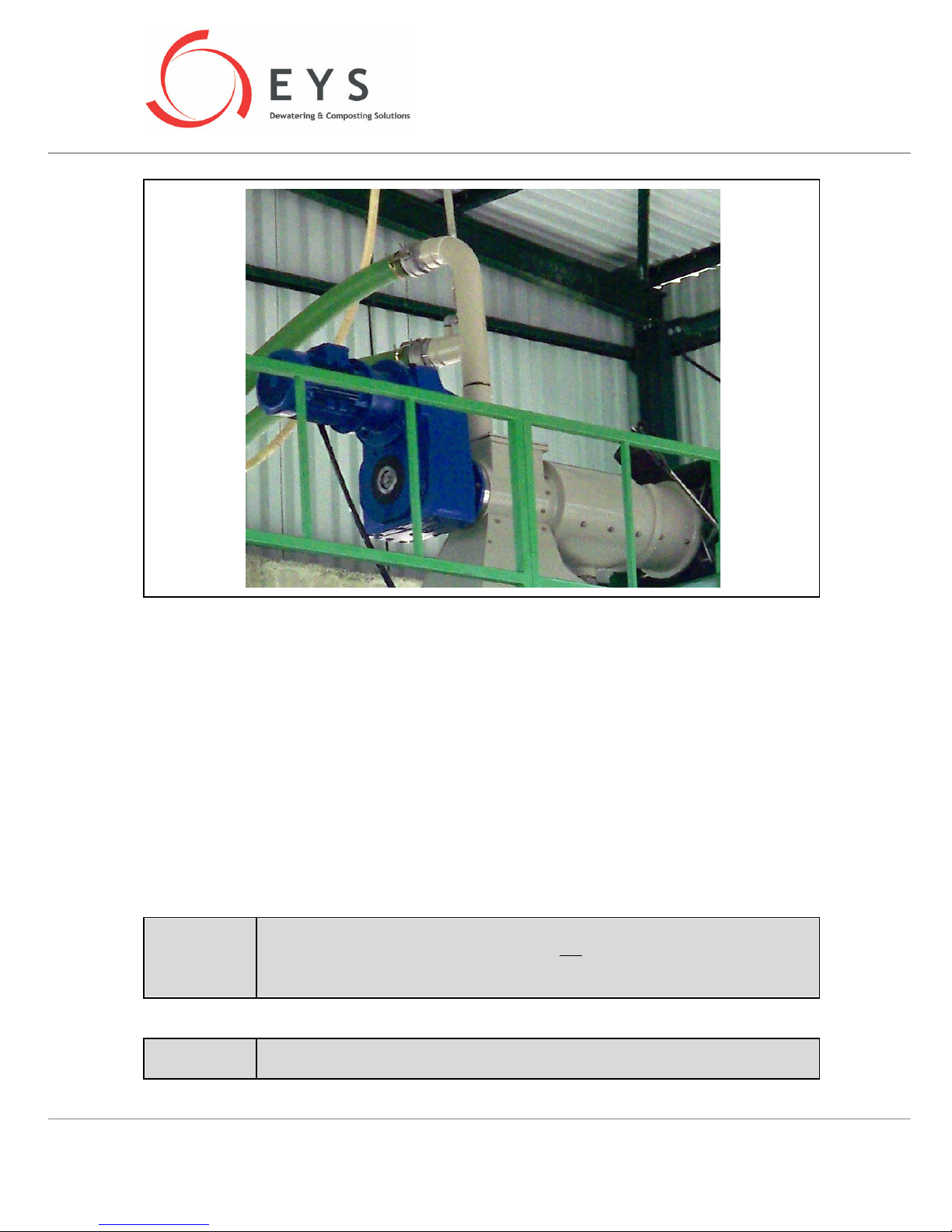
• Mount the F-Pipe to the inlet pipe of the separator.
• Mount the pump outlet pipe to the 6” upper inlet of the F-Pipe using the quick coupling
connectors.
• Mount a 6” over-flow pipe to the lower branch of the F-Pipe using the quick coupling connectors.
This overflow line will go directly back to the slurry pit where the pump is.
• Connect the 1,5” air-vent pipe to the over-flow line. This line will prevent a possible vaccum effect
on the over-flow line. This air-vent pipe should extend at least 1m above the upper branch of the
F-Pipe (pump line). Make sure that the valve on the air-vent pipe is free and open.
• Mount a 6” pipe to the liquid discharge outlet of the separator. This pipe will extend to the
separated liquid lagoon. The layout of this pipe should not cause dips along the path, which would
prevent the liquid to drain completely and may cause freeze-ups in the pipe.
• All electric work and connections must be carried out by a qualified electrician.
ATTENTION!
Overflow and separated liquid drainage lines must extend in a linear fashion to allow
easy flow of the slurry. Overflow line must not be submerged into the slurry pit,
otherwise it might creaate siphoning effect and divert all slurry flow from the pump
back into the same pit through the overflow line.
ATTENTION !
If the pump feeding the separator is not an EYS pump, then a suitable pump must be
used to supply the minimum flow rates as per the below table. Otherwise the
Page 12
“SP SERIES” USER MANUAL
Page 12 / 34
separation efficiency will be compromised. Pipe diameters should not be lower than
4” in order to minimize headloss.
SP400
SP600
SP800
SP600HD
SP800HD
Recommended
Pump Capacity
[m3/h]
20 50 75 20 50
5 PRE-STARTUP CHECKS
• Check the oil level in the gearbox, add the appropriate amount if necessary. Make sure the oil cap
is in place on the gearbox.
• Check that all piping connections are securely in place and free of any obstacles.
• Adjust the motor protection relay to the recommended value (factory settings for EYS supplied
control panels are: 4,4A for 2.2kW motor, 11A for 5.5kW motor, 22A for 11kW motor). The auger
of the separator turns counter-clockwise during separation. However with each start-up, the auger
first turns in clockwise direction (backwards) for 5 seconds in order to releave any excess pressure
on the gearbox due to potentially stuck solid plug inside the machine from the previous run.
• Remove the counterweights from the arms to minimize the counter pressure.
ATTENTION !
Make sure that the slurry pit where the separator is being fed from is free of foreign
ojects such as sand/metal/wood pieces that can harm the machine. The slurry pit is
an essential part of your separation system. Such foreign objects can cause
significant damage to auger and the screen of the separator, and abrasive materials
such as sand would wear out these two parts very quickly also.
6 START-UP
ATTENTION !
It is essential to mix the slurry in the slurry pit thoroughl
y prior to starting the
separator. Lack of proper agitation in the slurry is one of the main causes of low
separation efficiency. Agitation needs to be done prior to start of pumping so that
homogenous material is pumped to the separator.
6.1 Counter-pressure on discharge doors
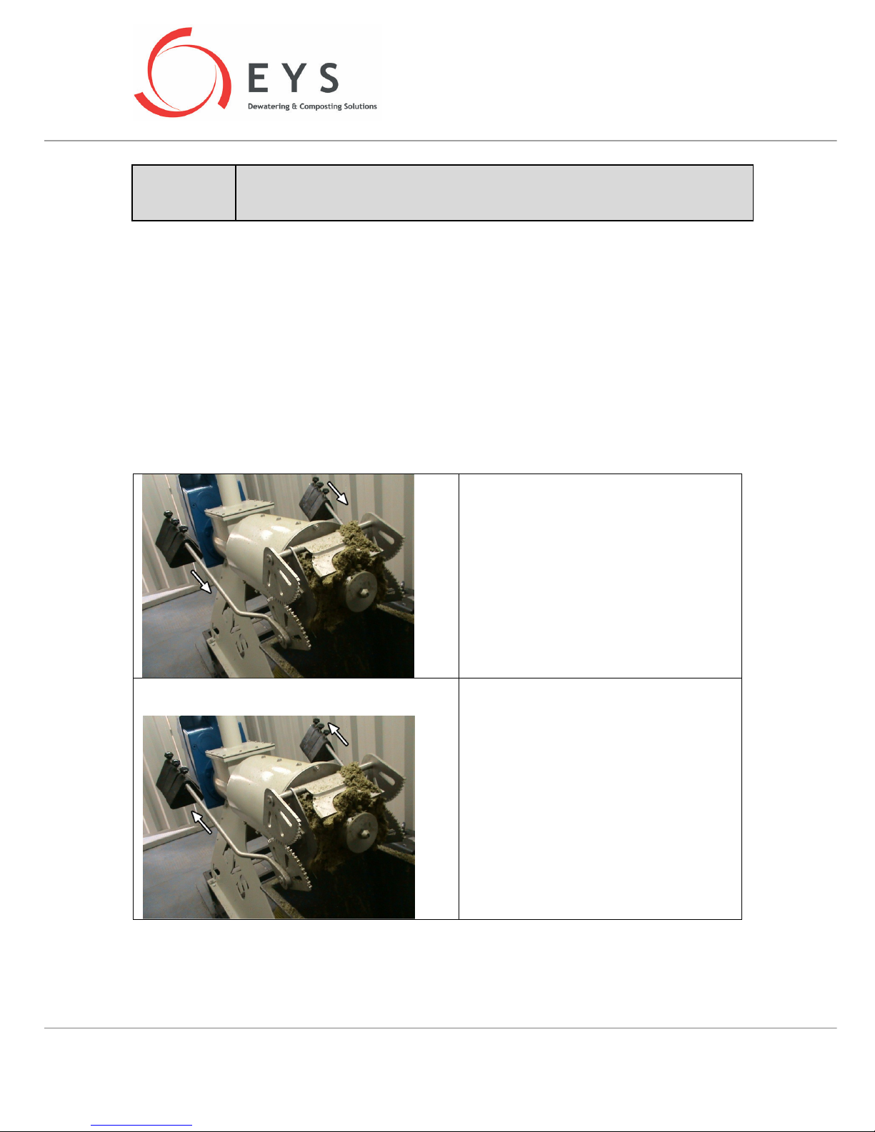
The consistency and dryness of the solid plug is adjusted by the positioning of the counter-weights on
the separator arms. Counter-pressure is increased as the weights are moved outwards towards the
open end of the arms.
Page 13
“SP SERIES” USER MANUAL
Page 13 / 34
ATTENTION !
W
ith each adjustment of the counter
-
pressure, the results will change after a minute
or two. Therefore please wait for a couple of minutes after each adjustment to
observe the change in solids output.
6.2 Establishing the solid plug
The solid plug will form soon after the separation system is started. First run-and-stop the pump for a
couple of seconds. Then wait until no slurry remains in the pipes, and repeat the procedure again. After
3-5 repeats, the plug will have established and solids will start coming out of the discharge end.
An alternative practice is to first open the discharge doors carefully and manually fill the space behind
the doors with straw or newspaper as a temporary plug. Then the separator and the pump can be
started up in sequence. The plug will form shortly after start up.
6.3 Plug adjustment
If the plug is too dry,
Push the counterweights forward or remove
some of the counterweights.
If the plug has dried up inside the separator
for a long time, it may stall the separator.
Always arrange the counterweights
symettrically on both arms of the separator.
If the plug is too wet,
Push the counterweights backward to apply
higher counter-pressure on the discharge
doors. If not enough, add on more
counterweight on each arm.
If the plug gets too loose, the plug may
breakdown and when that happens, liquid
slurry would shoot out from the solids
discharge. In that event stop the system and
re-start following the start-up procedures.
Making these adjustments will be necessary to reach optimum separation efficiency with a given
slurry consistency. Adjustments may need to be fine-tuned when the slurry consistency changes
significantly due to heavy rain, etc.
Page 14

“SP SERIES” USER MANUAL
Page 14 / 34
6.4 Other points of consideration
Overflow line back to the slurry pit must allow free flow of slurry within at all times.
Make sure that the overflow line is free of any obstacles and is not clogged and/or frozen
! In
regular operation, overflow line should be about 1/3 filled with slurry.
Excessive pump thoughput into the separator may lower separation efficiency.
If the pump chosen for the separation system delivers too high a flow, the slurry inlet into the
separator should be regulated with a valve on the inlet pipe.
Open end of the overflow pipe must not be submerged into slurry in the slurry pit; as this situation
would create a siphoning effect and all the slurry being pumped through the separator inlet pipe would
then flow back into the slurry pit, preventing the slurry from flowing into the separator.
Overflow and liquid slurry drainage lines should not be exposed to conditions that might change their
diameters (such as a vehicle driving over the line, other weights being applied on them, etc.). This
would increase the pressure inside the pipe and may cause the plug to shoot out from the separator.
In installations where two (or more) separators are installed side by side, one larger capacity pump can
be used instead of individual small pumps for each separator. In those instances, a collector buffer
tank can be arranged above the separators and a single pump can feed this collector, from which the
individual separators would be fed. A level control sensor would be useful in the buffer collector.
Slurry inlet pipe of the separator should not be smaller than 4” (Ø100mm). The inlet pipe should
maintain a constant diameter throughout its length. If these conditions can not be maintained, then
use of a bufferr tank above the separator and feeding the separtor from this tank would be
recommended.
Make sure the slurry is fully mixed prior to separation. This will prevent from loss of solids plug
unexpectedly due to very thin slurry input, or stalling of the separator motor due to very thick slurry
input. If the slurry pit very small (e.g., smaller than 100m3), then avoid over-agitation as this may
change the fiber structure of the slurry and make the slurry less separable.
The separator should be installed as close to the slurry pit as possible, in order to maintain the optimum
piping layout and minimize frictional losses inside the pipes. Layout of the pipes become particularly
important in situations where the horizontal distance between the separator and the pit is more than
10m. Make sure that the slurry pump line and the overflow line extend from the separator to the slurry
pit always with a downward inclination.
The separated liquid discharge of the separator is 4” (Ø100mm). Sthe liquid drainage line from the
separator to the separateed liquid lagoon should be a minimum of 4” (Ø100mm). In order to avoid
spihoning effect on this line, or to prevent freezing of slurry inside the pipe, or to avoid blockage as a
Page 15
“SP SERIES” USER MANUAL
Page 15 / 34
result of solids settlement inside the pipe, make sure that the line extends from the separator to the
liquid lagoon with a vertical inclination throughout its length.
In extremely cold climates, the pipelines can be wrapped with thermal insulation materials to prevent
freezing of the slurry. In any event, application of electric heaters around the pipes must be avoided
as these may pose a fire hazard in the vicinity of insulation materials.
Slurry pit is an integral part of your separation system, and it is essential that this pit is kept free of
foreign objects that might disrupt the slurry flow through the pipes and/or damage the separator
parts (such as metal parts / wires, plastic parts, wood pieces, sand, large pieces of cloth, plastic
bags, etc.). Mechanical and electrical damages that might occur as a result of such materials inside
the slurry are customer’s responsibility.
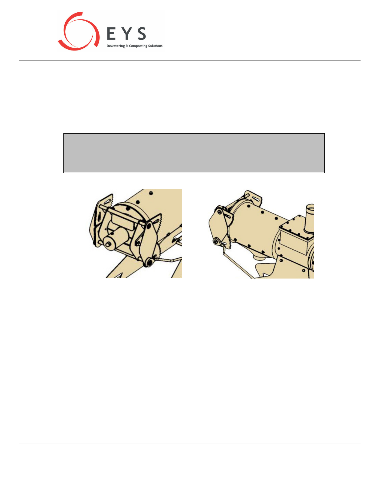
Solids discharge of EYS separators are designed with a gear mechanism that maximizes precision of
counter-pressure adjustment. Even though these gears do not move much during operation, hands
must be kept free of these areas at all times when the separtor is running. Make sure that the
protective cover is kept on at all times other than when servicing the machine. Loose outfits, sleeves
and gloves must be kept away from these gears with utmost attention. When servicing the machine,
utmost care must be taken when the protective cover is off; hands must be clear of the gears at all
times.
Page 16
“SP SERIES” USER MANUAL
Page 16 / 34
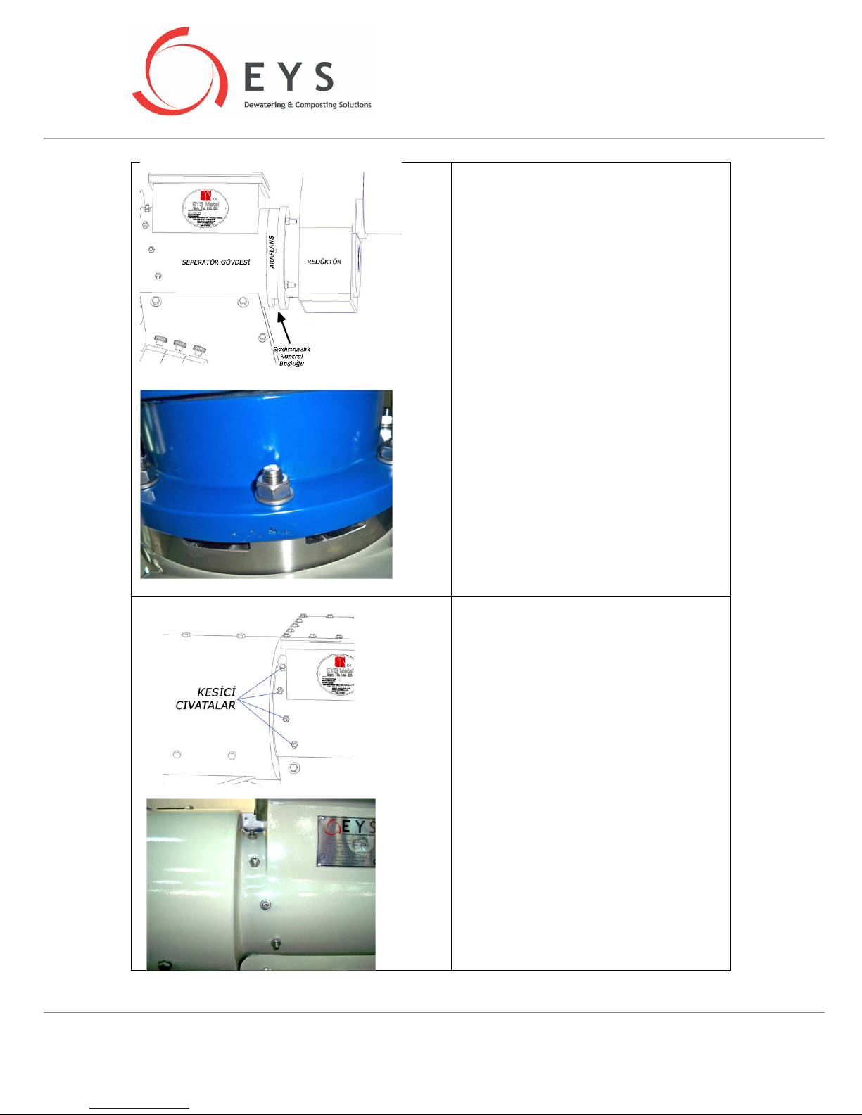
There is a “gearbox separation flange”
between the body of the separator and te
gearbox. This flange houses a combination of
seals that prevent slurry from running into
the gearbox. Should both seals fail inside this
flange, the slurry still doesn’t leak into the
gearbox but leaks down from an opening on
the underside of the flange. Operator should
visually check for any leaks in this area
periodically. If a leak is seen, the seals inside
the separation flange need to be replaced.
Call your dealer for help with these
replacements.
There are cutter screws on each side of the
separator at the slurry inlet area. These
screws are placed to catch long fibers and
otherwise foreign objects before they enter
the screen area and blind the screen. These
cutter screws are adjusted and fine-tuned at
the factory prior to shipping. Do not alter the
settings of these screws unless there is a
specific need for it.
Page 17
“SP SERIES” USER MANUAL
Page 17 / 34
7 TROUBLESHOOTING
Problem Potential Cause Solution
Seperator stalls Motor overload
Plug is too dry
Check the setting of the motor protection
relay in the control panel, make sure it is in
accordance with the maximum values in
table 13.2.3.
Foreign objects blocking the
auger
Clean the auger, screen and the separator
inlet area under the F-pipe.
Low solids output, very dry
solid plug
Too much counter-pressure on
discharge doors
Re-adjust counterweights (See section 5.1)
Premature wear of auger
and screen
Abrasive foreign materials in
slurry (e.g. sand, too much straw,
etc.)
Control the material flow to the slurry pit to
keep such materials out of the slurry.
Frequent changes in
dryness of the solid plug;
Changing slurry consistency Make sure the slurry in the pit is mixed
thoroughly
very low solid and liquid
discharge from the
separator
Insufficient slurry inflow to the
separator
Double check rotational direction of the
pump. Make sure pump line is free of
obstacles and blockage.
If the slurry is too thick to be pumped
effectively, dilute it to enable easy flow of
slurry.
Overflow line is siphoning the
slurry back into the slurry pit.
Make sure the air-vent line on the overflow
pipe is open and functioning .
Adjust the pump flow into the separator
with a valve if the pump is too powerful.
Overflow line should be filled with slurry
upto 1/3 to ½ of its diameter.
Make sure the overflow line is free of any
obstacles and is not blocked.
Make sure that the overflow line is NOT
submerged into slurry in the slurry pit.
Screen is blinded Run the separator auger backwards to help
clean the screen.
Take the screen out and clean it.
Worn auger and/or screen Check the auger outer diameter and the
tolerance between the auger and the
screen. Replace if necessary.
Screen is worn only in one
narrow section
Check screen guide-rail adjustments
Page 18
“SP SERIES” USER MANUAL
Page 18 / 34
Problem Potential Cause Solution
No solids output, very little
separated liquid output
Auger is turning backwards Check the electrical connections, reverse
connections if necessary.
Solids are stuck between auger
flighting and are co-rotating with
the auger
Take out and clean the auger.
Plug is breaking down and
liquid slurry is coming out
with solids
Very low solid material in the
incoming slurry (very thin slurry).
Counterweights are too far out
towards the discharge end of the
arm (not enough counterpressure)
Make sure slurry pit is agitated properly.
Use a smaller slot-size screen, if the
incoming slurry is too thin despite
sufficient agitation.
Refer to section 5.1
Slurry is leaking from
underside of the gearboxseparation flange
continuously
Seals inside the flange need to be
replaced
Replace the seals.
***NOTE:
It is normal for a small amount of slurry to
leak from these seals during the first
couple of days of operation after the first
start-up, until the seals are saturated with
liquid. Then the leak would stop.
Very little or no solids
output, no separated liquid
output, and most slurry is
flowing back through the
overflow line
Overflow line is siphoning the
slurry back into the slurry pit
Separated liquid discharge line is
blocked / clogged
Make sure the air-vent line on the
overflow pipe is open and functioning .
Make sure the overflow line is free of any
obstacles and is not blocked.
Make sure that the overflow line is NOT
submerged into slurry in the slurry pit.
Clean the inside of the separator body.
Check the liquid drainage line and
eliminate any blockages. Make sure the
liquid discharge line/pipe is not kinked or
clogged.
Very little or no solids
output, most slurry is
flowing back through the
overflow line; but there is
separated liquid output
The inlet area of the separator is
blocked
Dismantle the F-pipe and clean the inlet
area of the separator.
Very little solids in the slurry
(slurry too thin)
Cut any external water sources draining
into the slurry pit.
Make sure that the separated liquid from
the separator is not directed back into the
slurry pit!
Slurry is coming out of the
air-vent line
Pumping and overflow
connections are incorrect
Reverse the connections: make sure the
pump inlet is connected to the upper
branch of the F-pipe; and the overflow is
connected to the lower branch.
Page 19
“SP SERIES” USER MANUAL
Page 19 / 34
Air-vent line is too short. Make sure this
pipe is at least 1m long and minimum of 2”
in diameter
The separator throughput
drops significantly after a
period of proper operation
Slurry consistency change in the
slurry pit
Too much rainfall or other sources
of water flowing into the pit
Auger and/or screen worn out
Slurry that had been stored for a long time
may have been added to the pit prior to
separation. This causes the fibrous
structure of the slurry to loosen up and
makes the slurry less separable. Run the
separator until the slurry in the pit is used
up, then add fresh slurry into the pit.
Cut such diluting flows directed to the pit
Check the wear on auger and screen,
replace if necessary (see section 12)
8 STOPPING THE SEPARATOR
1. Turn off the pump.
2. Turn off the separator couple of minutes after the pump stops.
3. Seperator can be left idle as such for up to a week.
4. If the separator will remain idle for longer periods of time, then the inside of the separator should
be cleaned of any slurry inside.
5. In extreme cold weather conditions make sure all the pipes are emptied from slurry after the
operation, in order to prevent freezing inside the pipes.
9 LONG TERM STORAGE OF THE SEPARATOR
If the separator is going to be idle for extended periods of time, clean the machine by taking out the
auger and the screen, and assemble the cleaned parts back in.
If the machine will be shipped or taken out of commission for good, make sure to empty the gearbox
and dispose of the transmission oil in accordance with your local environmental regulations.
Page 20
“SP SERIES” USER MANUAL
Page 20 / 34
10 CHECKING THE SCREEN AND SCREEN GUIDE-RAILS
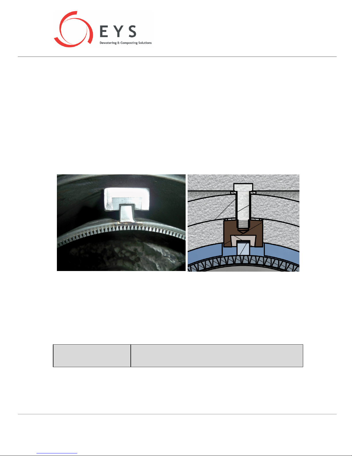
Screen(s) inside the separator and the guide-rails that hold the screen in place will wear out over time.
It is recommended to check these parts for potential wear every 1.000hrs of operation (roughly once
every 5-6 months for 6hr/day operation).
During these checks, first the screen should be removed from the machine and cleaned (preferably
with a pressure washer). Then visually check for any damages and visible wear on the parts. Also check
that the teflon inserts inside the guide-rails have a flat and continuous contact surface with the screen
as well as the bottom of the guide-rail itself. Worn out teflon inserts can cause subsequent damage to
the screen. If necessary, replace these teflon inserts each time you replace the screen.
See section 12 for details on acceptable levels of wear for these parts and how to control them.
Disassembly and assembly of the screen is explained in section 13.
Screen guide rails are fastened to the separator with 3 sets of screws each. These screws must not be
tampered with unless there is a specific need for it. These screws have been adjusted to the optimum
torque at the factory and typically would not need re-adjusting until the guide-rails and/or the teflon
inserts inside them are replaced. Please consult with your EYS dealer for details on how to make these
adjustments after a replacement.
ATTENTION !
Do not loosen the screws that hold the guide
-
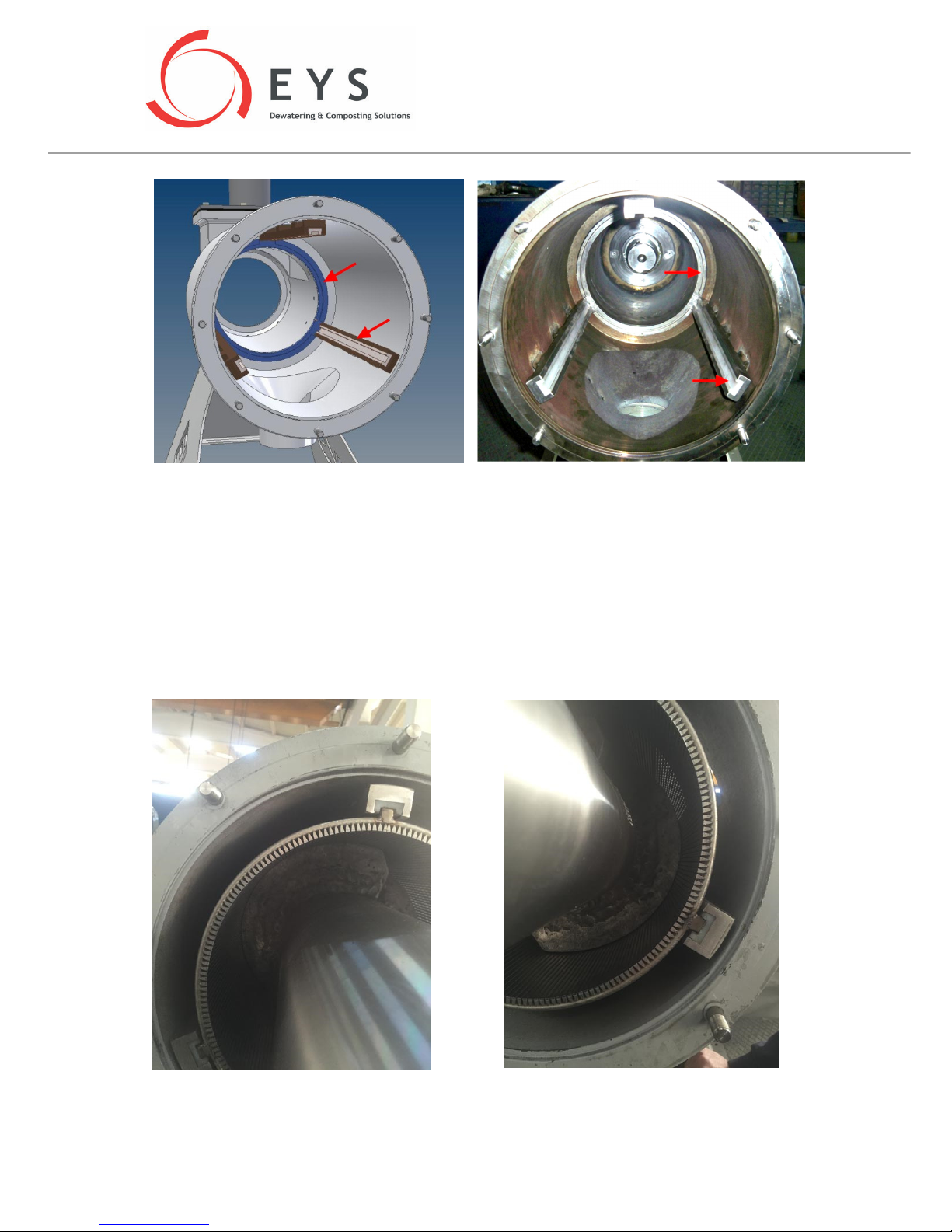
rails in place (see picture
in section 11.1; where these screws are denoted with [4]). Otherwise
the screen and the auger may get damaged.
Page 21
“SP SERIES” USER MANUAL
Page 21 / 34
Another part to be checked periodically is the “body wear ring” that sits at the deep end of the
separator body and supports the screen. This part prevents the screen to continually rub against the
body of the separator during operation. This part needs to be replaced when the wear on the diameter
reaches 1mm.
RE-ADJUSTING THE GUIDE RAILS
After replacement of a new screen, sometimes guide rails need to be re-adjusted. Operators can
understand if re-adjusting is necessary by measuring the distance between screen and auger or
listening any friction noise between screen and auger. You can see an example of misaligned screen at
below pictures:
Page 22
“SP SERIES” USER MANUAL
Page 22 / 34
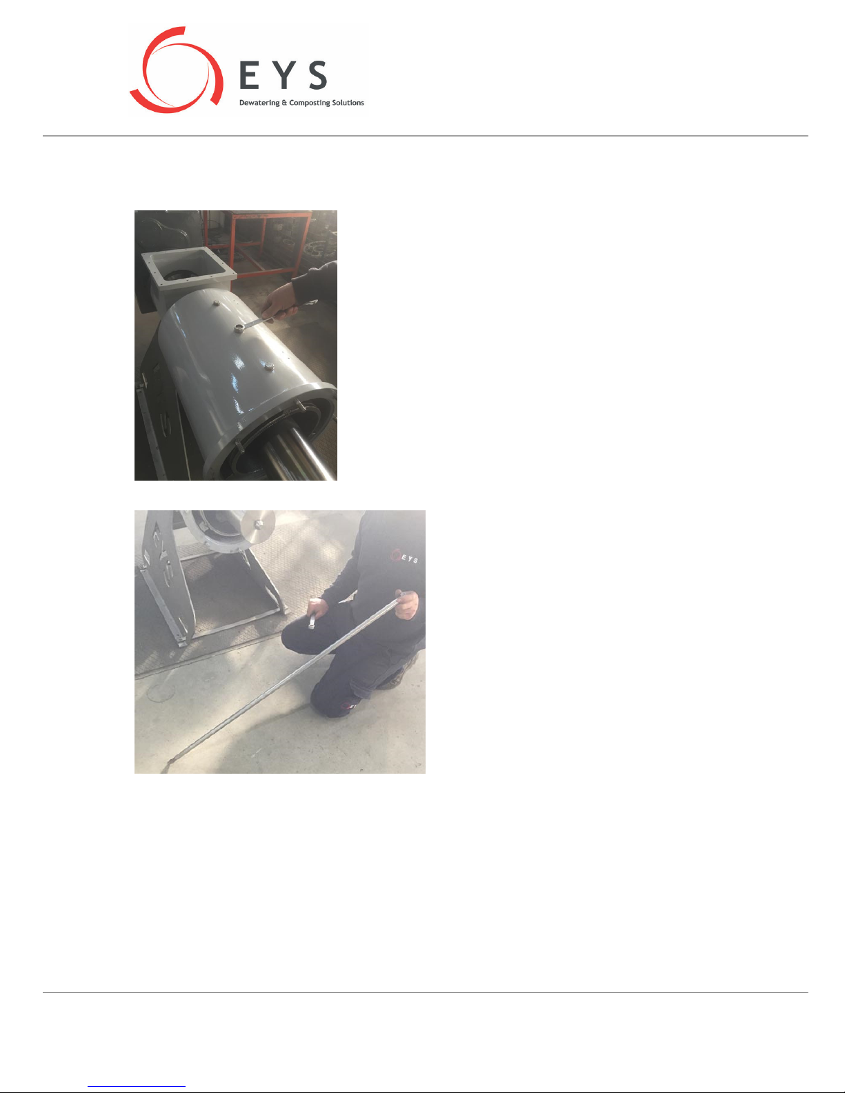
To re-adjust the screen position by guide rails, operator should loosen the bolts on the separator body
which will cause the screen move freely.
There are total 9 bolts on the body of SP400, SP600 and
SP600HD model Separators.
On the separator models of SP800, SP800HD, there are
total 15 bolts (9 on main body, 6 on small body).
For re-adjustment operation, a 1m length,
Ø20mm diameter profile can be used.
Page 23
“SP SERIES” USER MANUAL
Page 23 / 34
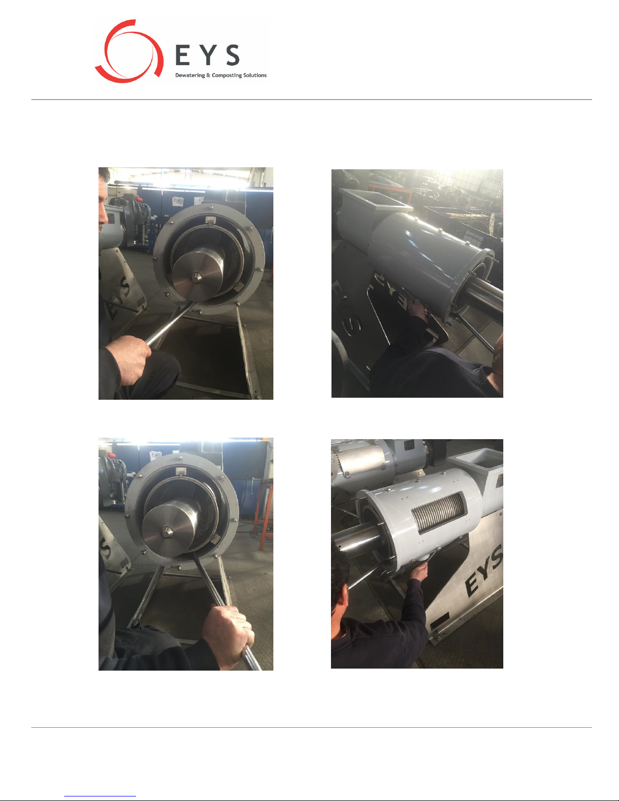
Put the profile between the inner diameter of the separator body and the outer surface of the screen.
Try to adjust the screen to a proper position by using the profile. When the friction noise is gone or the
distance between the auger and the screen is adjusted, tighten the bolts of the corresponding side.
Make the same adjustment to the other side and tighten the side bolts.
Page 24
“SP SERIES” USER MANUAL
Page 24 / 34
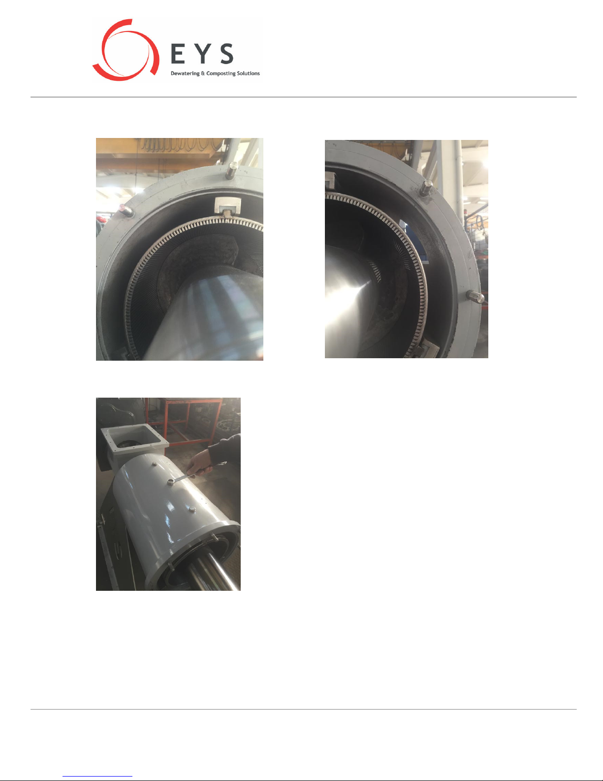
Check the distance between the auger and the sieve. Re-adjust the guide rails if necessary
If a proper re-adjustment achieved, tighten the top bolts on the separator body.
For re-adjusting the guide rails of SP800 and SP800HD
models, first remove the small screen and small body from
the separator. Finish the adjustment of the main body
guide rails, then mount the small body and finish the
adjustments of the guide rails of small body at last.
Page 25

“SP SERIES” USER MANUAL
Page 25 / 34
11 CHECKING THE AUGER
The auger is stainless steel and has special hard-coating applied on it for prolonged protection from
wear. Under normal operating conditions, the auger should last 2-3 times longer than the screen. But
it is recommended that the auger is also checked for wear and damage every time the screen is
checked. There can always be foreign materials mixed into the slurry stream, which can cause
premature damage to the flightings of the auger.
The wear typically happens on the outer diameter of the auger flightings along the length of the auger,
as well as the front face of the flightings wear the auger rubs against the solid plug towards the
discharge end. When the auger wears out at these points, soon premature wear and damage will likely
appear on the screen also. Please refer to section 12 for acceptable levels of wear on the auger.
Disassemble and assemble the auger as per the directions under section 13. Make sure that the cutter
screws explained in section 6.4 are not interfering with the auger. These cutter screws should first be
tightened until they touch the auger flighting, and then reversed back slightly (e.g. 30-45°) so as to
leave a small gap between the screw’s tip and the outer diameter of the auger flighting. If the screws
are touching the auger, then vibration and deflection from its rotational axis can be observed on the
auger. If this happens, re-adjust the cutter screws as explained above. Cutter screws should be checked
every 12.000hrs or operation, or each time the auger is replaced/removed.
12 ACCEPTABLE WEAR AND LIMIT TOLERANCES
All moving/working parts on the separator will eventually wear out. Periodic checks on these wear
parts is essential for prolonged life of these parts and for preventing disruption of service of your
separator. Worn parts need to be replaced after the limit tolerances are reached, otherwise they can
cause subsequent damage to other parts that are otherwise not yet due for replacement.
Immediate parts that are going to directly affect the operation of the separator once they are worn
are the screen and the auger. There can always be other reasons for malfunction or drop in separation
efficiency, so plese refer to the toubleshooting section of this manual first. The screens can not be
repaired once they are worn or damaged. Augers can be recoated if necessary. Augers can only be
recoated at EYS factory according to its original specifications.
WARNING !
D
o not use a non
-
authorized auger inside your separator
. No repairs
or rebuilds should be attempted on the auger. This would not only
void the manufacturer’s warranty, but can cause serious damage to
your machine. The screen can not be repaired once it’s worn or
damaged. Continueing to use worn/damaged screens by trying to
repair them will result in further undue damages to your machine,
and will void your manufacturer’s warranty.
Wear on the screen causes an increased ID (inner diameter) of the screen, as well as enlarged slotwidths between the screen wires. Wear on screen and auger affects the separation efficiency directly;
throughput drops, moisture level of the separated solids increases, amount of solids in the separated
liquid goes up. In standard models (non-HD models), normal operating tolerance between the screen
and the auger is 0.4mm-0.5mm on the radius (0.8mm-1.0mm in diameter). Tolerances above this range
Page 26
“SP SERIES” USER MANUAL
Page 26 / 34
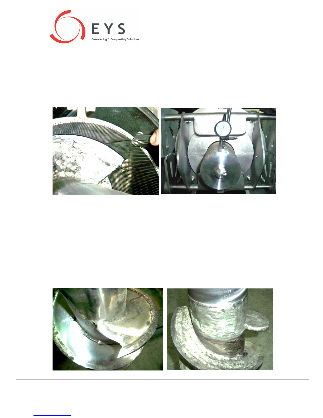
will start creating problems and should be avoided. If the screen is replaced, check the tolerance/gap
between the screen and the auger. If this gap is more than 1.0mm on the diameter, then the auger
needs to be replaced also. When the auger is replaced, its deflection from the rotational axis when
running should be measured by help of a comparator (see below pictures). Maximum acceptable
deflection on the diameter of the auger shaft is 0.25mm. Connection between the auger and auger
hub should be checked for cleanliness and greased to ensure a proper mating between these two parts.
Most important indication of screen and/or auger wear is a noticable drop in separation efficiency. If
such a drop in separation efficiency, or a significant increase in moisture of the separated solids, or
noticable increase in the solid content of the separated liquid is observed, it is possible that either the
screen or the auger (or both) will neeed to be replaced. Refer to the troubleshooting section of this
manual first to eliminate other possible causes for these problems prior to deciding on replacing the
screen/auger.
It should also be observed whether the hard-coating on the auger flightings is intact and visible. The
picture on the right below shows an auger on which the hard-coating is completely worn out and
vanished, as a result of which the flighting under the hard-coating has experienced irreversable wear
and damage. The picture on the left shows a proper auger with acceptable amount of hard-coating on
it.
Page 27
“SP SERIES” USER MANUAL
Page 27 / 34
If the auger isworn beyond repair, it might be more feasible to simply order a new auger rather than
shipping it back to EYS for a recoat. Please consult your dealer for assistance on auger replacements.
Amount of wear on the hard-coating layer can be determined by measuring the flighting thickness of
the auger. In all EYS separator models the flightings in the compression zone (flightings towards the
discharge end of the auger) are made of 10mm thick material, and then the hardcoating is applied.
Therefore if your measurement of the flighting thickness is 10mm or less, it means that the hardcoating
has been worn out completely.
When the screen is worn, it should be replaced without much delay. Otherwise the wearing of the
auger would be accellerated as well.
13 DISASSEMBLY AND ASSEMBLY
13.1 Disassembly
Partial disassembly of the separator parts will be necessary in the following circumstances.
• Cleaning of the auger and/or the screen
• Replacement of the auger and/or the screen.
• Cleaning of the separator body to get rid of blockages due to unexpected materials
• To clean the long-waited and dried up material inside the separator from the auger and screen
surfaces
First shut down the separator as per the instructions in section 8, and then follow the directions below.
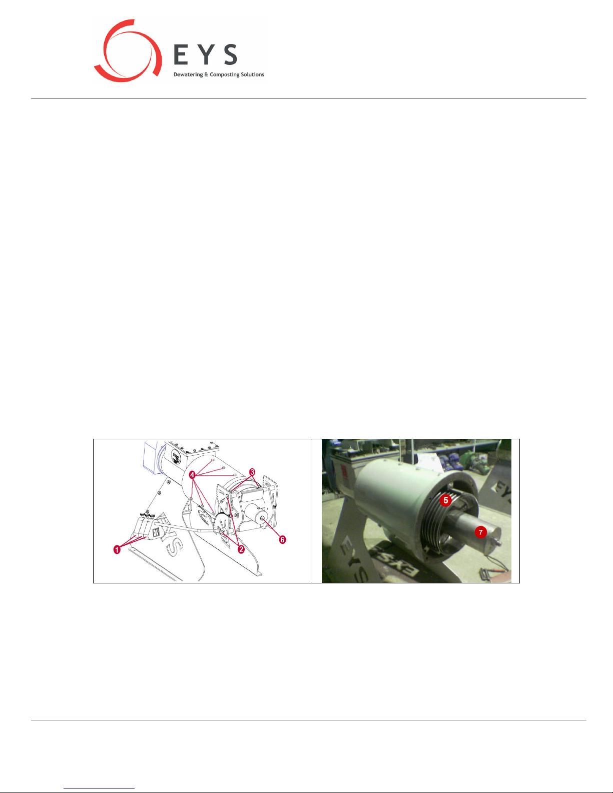
1. Remove all the counterweights [1] from the arms.
2. Do NOT remove the screws [2] that attach the arms to the discharge doors.
3. Remove the discharge mechanism altogether by removing the 8xM12 nuts [3] on the discharge
flange.
4. Do not touch the screws [4] holding the screen guide-rails in place.
5. Pull the screen out.
6. To remove the auger, loosen the M20 nut [6] on the end cover of the auger (the auger will
automatically release itself from the auger hub when this nut is undone).
Page 28

“SP SERIES” USER MANUAL
Page 28 / 34
7. Carefully pull the auger out.
WARNING !
Pay utmost attention not to put your hands between the gea
rs on the
discharge mechanism! Do not hold the discharge mechanism from
the gears or from the arms for your safety.
WARNING !
When removing the counterweights on the arms, remove them one
by one. When the positioning screws on the counterweights are
loosened, the weight may fall off the arm by gravity, which could be
dangerous. So always hold each counterweight by the other hand
when loosening the screw on the counterweight.
13.2 Assembly
Dismantled parts are assembled back onto the machine by following the steps under 13.1 in the
reverse order. Once all parts are assembled back together, make sure all moving parts can move
freely.
When assembling the auger, clean the mating surfaces of the auger stem and the auger hub, and
apply grease on these surfaces t o ensure a secure grip between the two parts. Then tighten the M20
nut on the end cover of the auger ([6] in the above figure) .
ATTENTION !
If any unforeseen problems are encountered or an additional step
other than the ones explained above seems to be necessary during
disassembly and assembly, contact your dealer for advise.
ATTENTION !
While disassembling or assembling the machine, do not use impact
tools such as a hammer. Screen, screen guide rails or auger are
precision parts that can be damaged by such tools.
Page 29
“SP SERIES” USER MANUAL
Page 29 / 34
14 GENERAL MAINTENANCE
Gearbox
The motor and the gearbox of your separator come ready to use when the machine is delivered. The
gearbox is already filled with the necessary amount of oil. The gearbox oil should be changed every
10.000hr of operation. Please refer to section 16 for motor and gearbox specifications.
Greasing
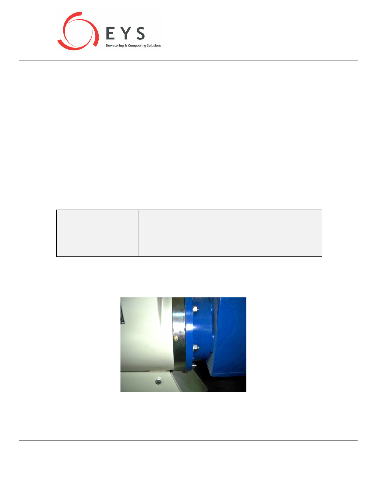
Gearbox separation flange needs to be greased regularly for the seals inside it. This needs to be
repeated every 2.000hours of operation at a minimum (weekly intervals would be better). There is a
greasing tip on the flange (see above figure). Make sure to clean this tip clean before and after each
greasing.
Cleaning
If the screen is clogged with long fibers and/or other blocking material, clean the screen thoroughly
from both inside and outside, preferably with a pressure washer.
WARNING !
When the machine is running, never touch/hit/lean on any moving
parts. Any intervention must be done after the machine has been
stopped and the power shut off. Cut off all power to the control panel
of the machine from the outside switch on the control box. Make sure
that nobody else can start the machine while you are working on it.
Never put your hands on or near the turning auger.
15 STORAGE
If your EYS separator will not be used for prolonged periods, it is best to uninstall the machine and
keep it in a dry and safe enclosure. It i also recommended to place some moisture absorbants (such as
silica gel) in the electrical connection box on the motor. Replace the gearbox oil (with AGIP VSF 320 or
equivalent). Dispose of the old oil in accordance with your local environmental regulations.
Page 30
“SP SERIES” USER MANUAL
Page 30 / 34
16 TECHNICAL SPECIFICATIONS
16.1 Seperator Technical Specifications
SP400
MOTOR
Q1E100L4A
-
05H PA100L4A
-42-
Q3EH
Q2E100L4C
-KG-H
Power
2,2 kW
2,5 kW
2,2 kW
2,2 kW
2,2 kW
2,5 kW
Voltage
220/380 V
255/440 V
230/460 V
230/460 V
220/380 V
255/440 V
Freq.
50 Hz
60 Hz
50 Hz
60 Hz
50 Hz
60 Hz
Rpm
1430
1715
1460
1750
1430
1725
GEARBOX
PD32100L4A
PD32
PD32
Oil
BP ENERGOL GR
-
XP220
BP ENERGOL XP220
BP XP220
ENERGY
İ
52,92
64,11
52,92
Rpm
27 32 23 27 27 33
IEC / PAM
N/A PAM100L4A
PAM100
L4C
SP600
MOTOR
132M/4B
132M/4C
132M/4B
Power
5,5 kW
6,3 kW
4,8 kW
5,5 kW
5,5 kW
6,3 kW
Voltage
380/660 V
440/760 V
230/460 V
230/460 V
380/660 V
440/760 V
Freq.
50 Hz
60 Hz
50 Hz
60 Hz
50 Hz
60 Hz
Rpm
1430
1715
1460
1735
1430
1715
GEARBOX
PD42 132M/4C
PD42
PD42
Oil
KLUBERSYNTH
GH 6
-
320
İ
43,65
52,23
43,65
Rpm
38 39 28 33 38 39
IEC / PAM
PAM132M/4B
PAM132M/4B
PAM132M/4B
SP800
MOTOR
132M/4B
132M/4C
Power
5,5 Kw
6,3 kW 4,8 kW
5,5 kW
Voltage
380/660 V
440/760 V
230/460 V
230/460 V
Freq.
50 Hz
60 Hz
50 Hz
60 Hz
Rpm
1450
1740
1460
1730
GEARBOX
PD52 PAM132M/4C
PD52 PAM132S/4C
Oil
KLUBERSYNTH GH 6
-
320
İ
41,96
51,45
Rpm
35 41 28 34
IEC / PAM
PD52 PAM132M/4C
PD52 PA
M132M/4C
Page 31
“SP SERIES” USER MANUAL
Page 31 / 34
SP600HD
MOTOR
132M/4B
132M/4C
Power
5,5 Kw
6,3 kW
4,8 kW
5,5 kW
Voltage
380/660 V
440/760 V
230/460 V
230/460 V
Freq.
50 Hz
60 Hz
50 Hz
60 Hz
Rpm
1445
1730
1460
1730
GEARBOX
PD73 132S/4C
PD73 132S/4C
Oil
KLUBERSYNTH GH 6
-
320
İ
123,12
150,32
Rpm
12 14 10 12
IEC / PAM
N/A PD73 132S/4C IEC
SP800HD
MOTOR
132M/4C
160L/4A
Power
11 Kw
12,7 kW
9,6 kW
11 kW
Voltage
380/660 V
440/760 V
330/460 V
330/460 V
Freq.
50 Hz
60 Hz
50 Hz
60 Hz
Rpm
1450
1740
1475
1770
GEARBOX
PD73 IEC 132M/4C
PD73 IEC 160L/4A
Oil
KLUBERSYNTH GH 6
-
320
İ
59,52
68,14
Rpm
24 29 22 26
IEC / PAM
PD73 132S/4C IEC Ø32
PD73 160L 4A IEC Ø32
16.2 Machine Tags
When you call your dealer for consultance, service or replacement parts, please keep your machine
tag information handy. There are three separate tags on your separator – one on the separator body,
one on the gearbox and the other one on the motor.
16.2.1 Seperator tag
Model number, date of production and serial number are on this tag.
16.2.2 Gearbox tag
N. gearbox serial number
TYPE gearbox type/model
n2 gearbox output rpm
i transmission ratio
An additional sticker on the gearbox designates the oil type used in the gearbox.
Page 32
“SP SERIES” USER MANUAL
Page 32 / 34
16.2.3 Motor tag
Motor type/model, standards that it conforms to, serial number, insulation class, weight,
voltage/frequency and connection information, cos and motor rpm.
16.3 Warning signs
There are two warning sign stickers on the separator.
One is on the motor fan cover, and shows the operational rotation direction of the motor and the
auger.
The other one is on the gearbox separation flange, and shows the greasing tip where the grease is to
be applied during periodic checks.
17 ELECTRIC CONTROL PANEL
Contents of the electric control panel will vary depending on the components of your separation
system. EYS offers stand-alone control panels for each machine, as well as a single and central control
panel to command all components of the system.
17.1 Wiring diagrams
You can find the relevant wiring diagrams at the end of this manual.
17.2 Reverse-run of auger at start-up
Each time the separator is started from the control panel, the auger first turns in reverse direction for
a short period of time. This prevents damage to the gearbox due to any unexpected blockage inside
the machine left over from the previous run. Also, it helps clean the inside surface of the screen from
before the separation starts.
Following paragraph explains how these adjustments can be altered when necessary.
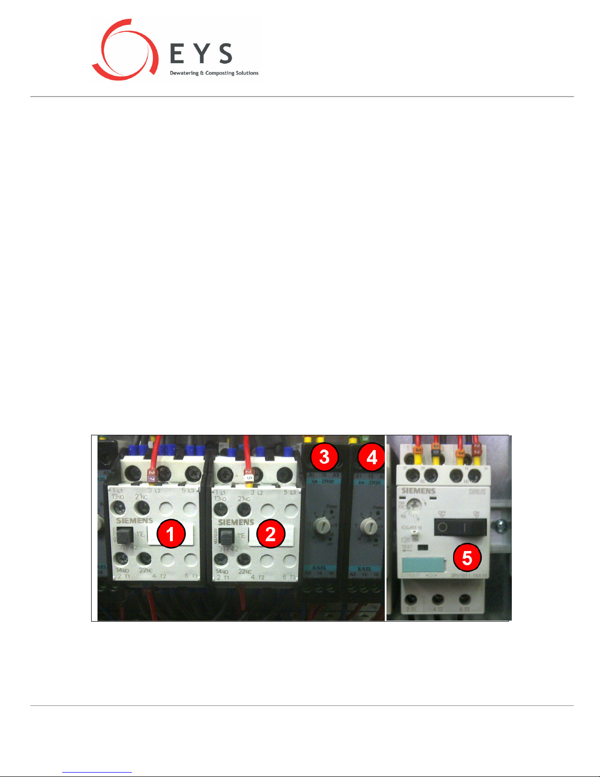
When the separator is started up, contactors [1] and [2] are activated. Each contactor commands the
auger to turn in one direction.
Page 33
“SP SERIES” USER MANUAL
Page 33 / 34
The time relay [3] adjusts the duration of reverse-run at the start-up (i.e. how long the auger will turn
backwards). The default factory setting is 5 seconds, which is the recommended value. It is possible to
increase it up to 30sec.
The time relay [4] adjusts the time lag after the finish of the reverse-run until the start of auger run in
the regular direction. This is also set to the default value of 5 seconds at the factory.
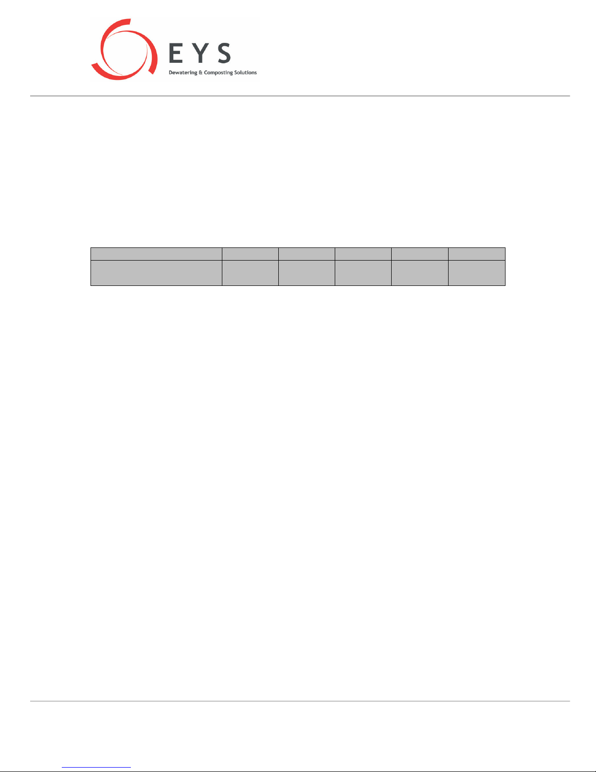
Motor protection relay [5] prevents the motor from burning as a result of drawing too high an amper
value. Default factory setting of this relay is as per the below table for each separator model. Do NOT
increase the setting of the motor protection relay above these values.
SP400
SP600
SP800
SP600HD
SP800HD
Motor Protection Relay
Max. Settings [Amper]
4 11 11 11 22
18 SPARE PARTS LIST
Parts list for your separator can be found at the end of this manual.
19 MANUFACTURER’S WARRANTY
All EYS products are under warranty for 12 months from the date of installation against all
manufacturing defects.
Page 34

“SP SERIES” USER MANUAL
Page 34 / 34
20 EC DECLARATION OF CONFORMITY
EC DECLARATION OF CONFORMITY
MANUFACTURER EYS METAL SAN. VE TİC. LTD. ŞTİ.
ADDRESS
ASTİM ORGANİZE SANAYİ BÖLGESİ HAVAALANI BULVARI HÜRRİYET
MAHALLESİ NO:233 TEPECİK, AYDIN, TURKEY
The undersigned Company certifies under its sole responsibility that the item of equipment specified
below satisfies the requirements of the Machinery Directive 2006/42/EC which applies to it. The
item of equipment identified below has been subject to internal manufacturing checks with
monitoring of the final assessment by EYS METAL SAN. VE TİC. LTD. ŞTİ.
PRODUCT SCREW PRESS SEPARATOR
MODEL / TYPE SP400, SP600, SP800, SP600HD, SP800HD
DIRECTIVES
MACHINERY DIRECTIVE 2006/42/EC
LOW VOLTAGE DIRECTIVE 2006/95/EC
REGULATIONS APPLIED ACCORDING TO HARMONIZED STANDARDS
EN ISO 12100:2010, EN 60204-1:2006, EN ISO 13857
Place and date of issue AYDIN / TURKEY 11.2012
Name and position of authorized person
ORHUN ÇETİN
TECHNICAL MANAGER
Signature of authorized person
 Loading...