


EyeTech VT2
Hardware Installation Manual
Updated: March 2011

1.0 Introduction
Table of Contents
1.0 Contact information .......................................................... 2
1.1 Safety Information on Infrared (IR) Lights ............................ 4
1.2 Safety Information on Magnetic field strength........................ 4
2.0 Installation ................................................................... 5
2.1 Room Lighting ................................................................... 5
2.2 Desktop Installation of VT2 ................................................. 5
2.3 Tabletop Installation of VT2 ................................................. 7
TM3 Hardware Installation Manual ©Eyetech Digital Systems, Inc. Modified on 4/10/2008
2

1.0 Introduction
Website:
www.eyetechds.com
Phone:
480-704-3158
Fax:
480-718-5243
Email:
info@eyetechds.com
General product information
support@
eyetechds.com
Technical support
service@eyetechds.com
Order placement and inquiries about
existing orders
Contact Information:
Corporate Headquarters:
EyeTech Digital Systems
1128 E Greenway St. Suite 1
Mesa, AZ 85203-4362
USA
1.0 Contact information
TM3 Hardware Installation Manual ©Eyetech Digital Systems, Inc. Modified on 4/10/2008
3

1.1 Safety Information
1.1 Safety Information on Infrared (IR) Lights
VT2 uses IR lights to illuminate the eyes and provide reference points for the eye
tracker. The IR light is produced by LED’s at a wavelength of 850 nanometers. This
type of IR light occurs naturally in sunlight and in light from incandescent lamps.
The total power consumed by the lights is approximately 3 watts. The measured
irradiance at the user’s eye under normal operating conditions is less than 1
milliwatt per square centimeter. This is well within the safety guidelines given in
the book 1996 TLVs and BEIs by the American Conference of Governmental
Industrial Hygienists.
You may want to consider replacing incandescent bulbs with compact fluorescent
bulbs if you experience lighting problems.
1.2 Safety Information on Magnetic field strength
The VT2 uses internal magnets, as a result close proximity to a pace maker or
implantable cardioverter-defibrillator (ICD) may result in deactivation of these
medical devices. It is not recommended to get the VT2 within 2 inches of a pace
maker or ICD.
TM3 Hardware Installation Manual ©Eyetech Digital Systems, Inc. Modified on 4/10/2008
4
2.0 Installation
2.0 Installation
2.1 Room Lighting
Fluorescent lights have no effect on the VT2 eye tracker. Incandescent lights or
windows may degrade the operation of VT2, especially if the light source is behind
the monitor or behind the user. A light source directly to the side or directly above
the user will not usually be a problem. Changing incandescent light bulbs to
compact florescent bulbs may improve the performance of the VT2.
2.2 Desktop Installation of VT2
NOTE: VT2 hardware is usually provided with either a table top stand or a VESA mount
to be attached to a desktop monitor.
TM3 Hardware Installation Manual ©Eyetech Digital Systems, Inc. Modified on 4/10/2008
5
2.0 Installation
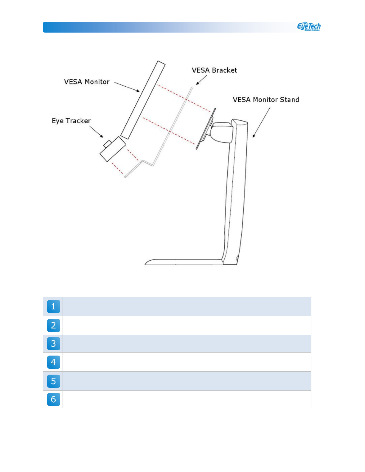
Line up the four mounting holes on the VT2 tracking module with the four
mounting holes on the VT2 VESA bracket.
Insert each of the four screws provided with the bracket in the mounting holes
from the back of the stand and tracking module.
Tighten the four screws with the included wrench.
Line up the four mounting holes on the VESA monitor with the four mounting
holes on both the VT2 VESA bracket and the VESA desktop stand.
Insert each of the four screws provided with either the VESA desktop stand or
the VESA monitor into the four mounting holes on the VESA monitor.
Insert spacers as needed and then tighten the four screws.
TM3 Hardware Installation Manual ©Eyetech Digital Systems, Inc. Modified on 4/10/2008
6
2.0 Installation
2.3 Tabletop Installation of VT2
Line up the four mounting holes on the VT2 tracking module with the four
mounting holes on the VT2 stand.
Insert each of the four screws provided into the mounting holes on the back of
the stand and tracking module.
Tighten the four screws with the included wrench.
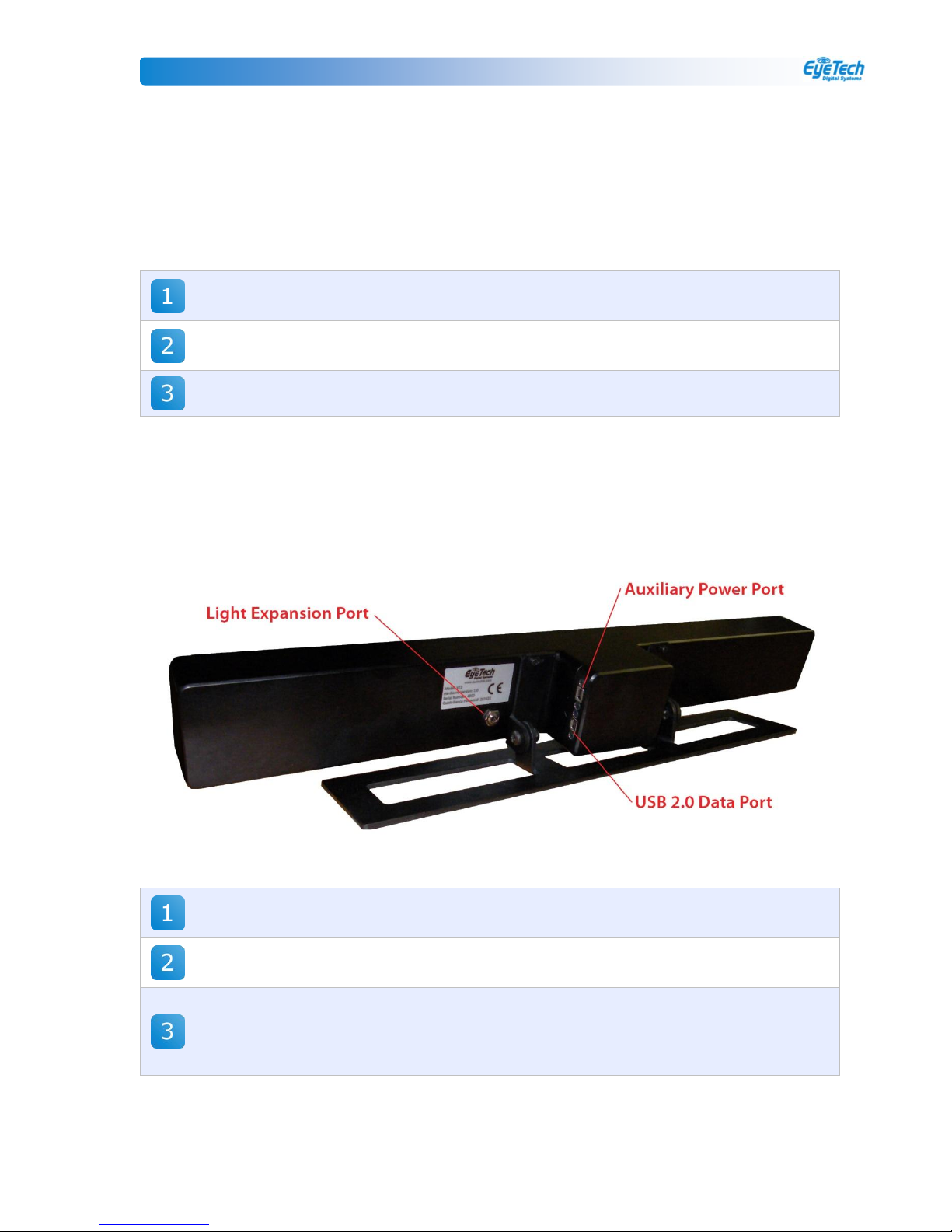
USB 2.0 Data Port: Connect the system to the computer via the USB 2.0
cable plugged into the USB 2.0 Data Port shown above.
Light Expansion Port: Usage of the Light Expansion Port is optional and is
for adding additional light arrays for custom installations.
Auxiliary Power Port: Some computer systems may require the use of the
Auxiliary Power Port in addition to the Data Port. Verify that the red LED light
on the bottom of the camera is on. If it is not, the camera is not receiving
power from the USB 2.0 port.
Place the VT2 eye tracker on the tabletop stand as close to the bottom of the monitor as
possible.
2.4 VT2 Ports
The VT2 Eye Tracker has 3 ports.
TM3 Hardware Installation Manual ©Eyetech Digital Systems, Inc. Modified on 4/10/2008
7
 Loading...