

EYEsurv ESIP-MP3-BTZF1 Quick Start Manual

HD IR Waterproof Fixed Network Camera Quick Start Guide
Version 1.0.0

i
Welcome
Thank you for purchasing our network camera!
This quick start guide is designed to be a reference tool for your system.
Please keep this start guide well for future reference.
Please open the accessory bag to check the items one by one in accordance with the list below.
Contact your local retailer ASAP if something is missing or damaged in the bag.
Before your operation please read the following instructions carefully.
1.Electrical safety
All installation and operation here should conform to your local electrical safety codes.
The power shall conform to the requirement in the SELV (Safety Extra Low Voltage) and the Limited
power source is rated 12V DC or 24V AC in the IEC60950-1. (Refer to general introduction) Please
note: Do not connect two power supplying sources to the device at the same time; it may result
in device damage!
We assume no liability or responsibility for all the fires or electrical shock caused by improper handling
or installation.
We are not liable for any problems caused by unauthorized modification or attempted repair.
2.Transportation security
Heavy stress, violent vibration or water splash are not allowed during transportation, storage and
installation.
3.Installation
Do not apply power to the camera before completing installation.
Please install the proper power cut-off device during the installation connection.
Always follow the instruction guide the manufacturer recommended.
4.Qualified engineers needed
All the examination and repair work should be done by the qualified service engineers.
We are not liable for any problems caused by unauthorized modifications or attempted repair.
5.Environment
This series network camera should be installed in a cool, dry place away from direct sunlight,
inflammable, explosive substances and etc.
Please keep it away from the electromagnetic radiation object and environment.
Please make sure the CCD (CMOS) component is out of the radiation of the laser beam device.
Otherwise it may result in CCD (CMOS) optical component damage.
Please keep the sound ventilation.
Do not allow the water and other liquid falling into the camera.

ii
Thunder-proof device is recommended to be adopted to better prevent thunder.
The grounding studs of the product are recommended to be grounded to further enhance the reliability
of the camera.
6. Daily Maintenance
Please shut down the device and then unplug the power cable before you begin daily maintenance
work.
Do not touch the CCD (CMOS) optic component. You can use the blower to clean the dust on the lens
surface.
Always use the dry soft cloth to clean the device. If there is too much dust, please use the water to
dilute the mild detergent first and then use it to clean the device. Finally use the dry cloth to clean the
device.
Please put the dustproof cap to protect the CCD (CMOS) component when you do not use the camera.
Dome enclosure is the optical component, do not touch the enclosure when you are installing the
device or clean the enclosure when you are doing maintenance work. Please use professional optical
clean method to clean the enclosure. Improper enclosure clean method (such as use cloth) may result
in poor IR effect of camera with IR function.
7. Accessories
Be sure to use all the accessories recommended by manufacturer.
Before installation, please open the package and check all the components are included.
Contact your local retailer ASAP if something is broken in your package.
Accessory Name
Amount
Network Camera Unit
1
Quick Start Guide
1
Installation Accessories Bag
1
12V to 24V Conversion Cable
(For AC 24V series product only)
1
CD
1

iii
Table of Contents
1 Framework..................................................................................................................... 1
1.1 Multiple-function Combination Cable................................................................. 1
1.2 Framework and Dimension ............................................................................... 2
1.3 Bidirectional talk ................................................................................................ 3
1.3.1 Device-end to PC-end................................................................................. 3
1.3.2 PC-end to the device-end ........................................................................... 3
1.4 Alarm Setup ...................................................................................................... 3
2 Device Installation ......................................................................................................... 5
2.1 Device Installation ............................................................................................. 5
2.2 Install Micro SD Card ........................................................................................ 5
2.3 Adjust Lens ....................................................................................................... 6
2.4 Adjust Bracket ................................................................................................... 7
2.5 Button................................................................................................................ 8
3 Quick Configuration Tool ............................................................................................. 10
3.1 Overview ......................................................................................................... 10
3.2 Operation ........................................................................................................ 10
4 Web Operation ............................................................................................................ 12
4.1 Network Connection ........................................................................................ 12
4.2 Login and Main Interface ................................................................................. 12
Appendix Toxic or Hazardous Materials or Elements ........................................................ 14
1
1 Framework
1.1 Multiple-function Combination Cable
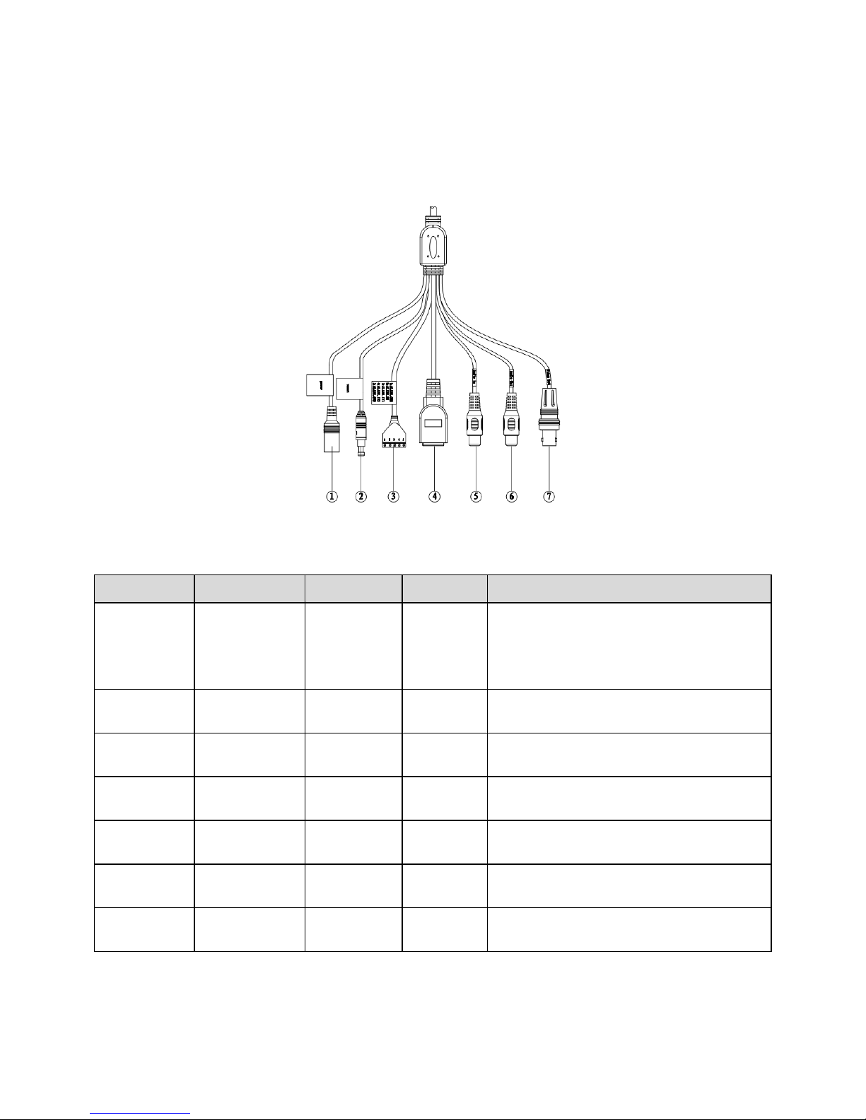
You can refer to the following figure for multiple-function combination cable information. See
Figure 1-1.
Figure 1-1 Multiple-function combination cable
Please refer to the following sheet for detailed information.
SN
Port Name
Function
Connection
Note
1
DC12V/AC24V
Power input
port
/
Power port. Input DC 12V or AC 24V.
(convertor is required)
Note:
Please refer to actual device label.
2
RESET
Reset button
/
The reset button is to restore device factory
default setup. Press 3~5 seconds.
3
I/O
I/O cable
port
/
Includes alarm input and output.
4
LAN
Network port
Ethernet
port
Connect to standard Ethernet cable.
5
AUDIO IN
Audio input
port
RCA
Input audio signal. It can receive the
analog audio signal from the pickup.
6
AUDIO OUT
Audio output
port
RCA
Output audio signal to the devices such as
the sound box.
7
VIDEO OUT
Video output
port
BNC
Output analog video signal. It can connect
to the TV monitor to view the video.
Please refer to the follow sheet for detailed pin information.
2
Port Name
SN
Name
Note
I/O Port
1
ALARM_COM
Alarm output public port.
2
ALARM_NO
Alarm output port. It is to output the alarm signal to
the alarm device.
NO: normal open alarm output port.
It shall work with ALARM_COM port.
3
ALARM_IN1
Alarm input port 1. It is to receive the on-off signal
from the external alarm source.
4
ALARM_IN2
Alarm input port 2. It is to receive the on-off signal
from the external alarm source.
5
GND
Ground port
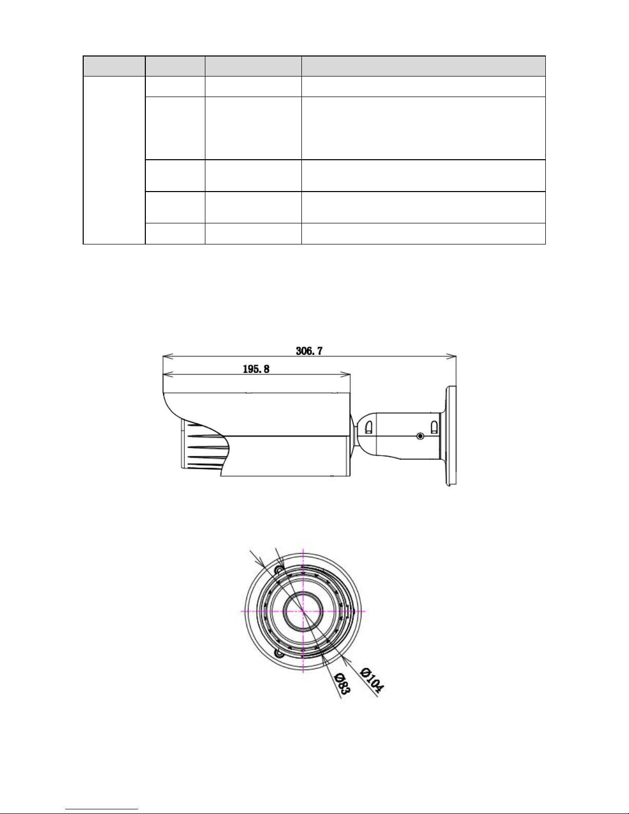
1.2 Framework and Dimension
Please refer to the following figure for dimension information. The unit is mm. See Figure 1-2 and
Figure 1-3.
Figure 1-2 Dimension illustration 1
Figure 1-3 Dimension illustration 2
 Loading...