

Eyeris ERN-LWG3065N, ERN-LW3065P, ERN-LWG4065N, ERN-LW4065P Installation And Operating Instruction Manual
www.eyerisdigital.com
Installation and Operating
Instruction Manual
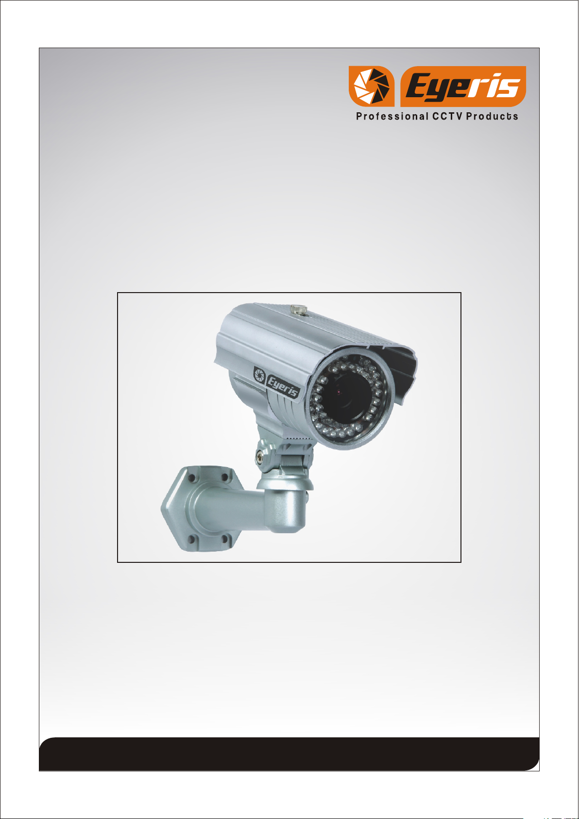
TRUE WDR WITH SMART IR FUNCTION
NIGHTVISION OUTDOOR BULLET CAMERA
ERN-LWG3065N/LW3065P
ERN-LWG4065N/LW4065P
Thank you for your purchase of this product.
Before attempting to connect or operate this product, please read these instructions
completely.
Product specifications and its contents subject to change without any prior notice.
The picture is for reference, the object as the standard.
Page 1

1. General Information
- Safety Precaution
- Package contents
2. Installation of Camera
- Camera Connection
- Installation of Camera
- Tips for Camera Location
- Dimension
3. Operation Guide
- Menu Structure
- Function Description
4. Technical Specification
CONTENTS
5. Troubleshooting
6. Cleaning and Care
7. Maintenance and Support
Page 2

1.General Information
> Safety Precaution
1.Read these instructions carefully before commissioning the camera in order to avoid
damages caused by improper installation or use.
2.Do not abuse the camera. Avoid striking, shaking, etc. The camera could be damaged
by improper handing or storage.
3.Use a dry cloth to clean the camera front glass when dirty. When the dirt is hard to
remove, use a mild detergent and wipe gently. Then wipe off the remaining detergent
with a dry cloth.
4.Do not aim the camera at bright objects. Whether the camera is in use or not, never aim
it at the sun or other extremely bright objects. Otherwise, blooming or smears may be
caused.
5.In case of outdoor use, you have to install the camera in a suitable weather protection
case incl. heating element.
6.Operate the camera with the designated voltage only.
7.Use the camera at temperatures within -10 C to +50 C and humidity below 90%.
> Package Contents
1.
True WDR With Smart IR Function Nightvision Outdoor Bullet Camera
2.Operating Instructions
3.Mounting Template Sticker
Caution
To Reduce the risk of electric shock, do not remove cover. No
user serviceable parts inside. Refer servicing to qualified
service personnel.
Page 3
2.Installation of Camera
> Camera Connections
12V DC Power Supply
Use standard 12V DC output power supply with 2.1mm
standard DC power female pin. Before connect power check
power supply polarity (+ and -).
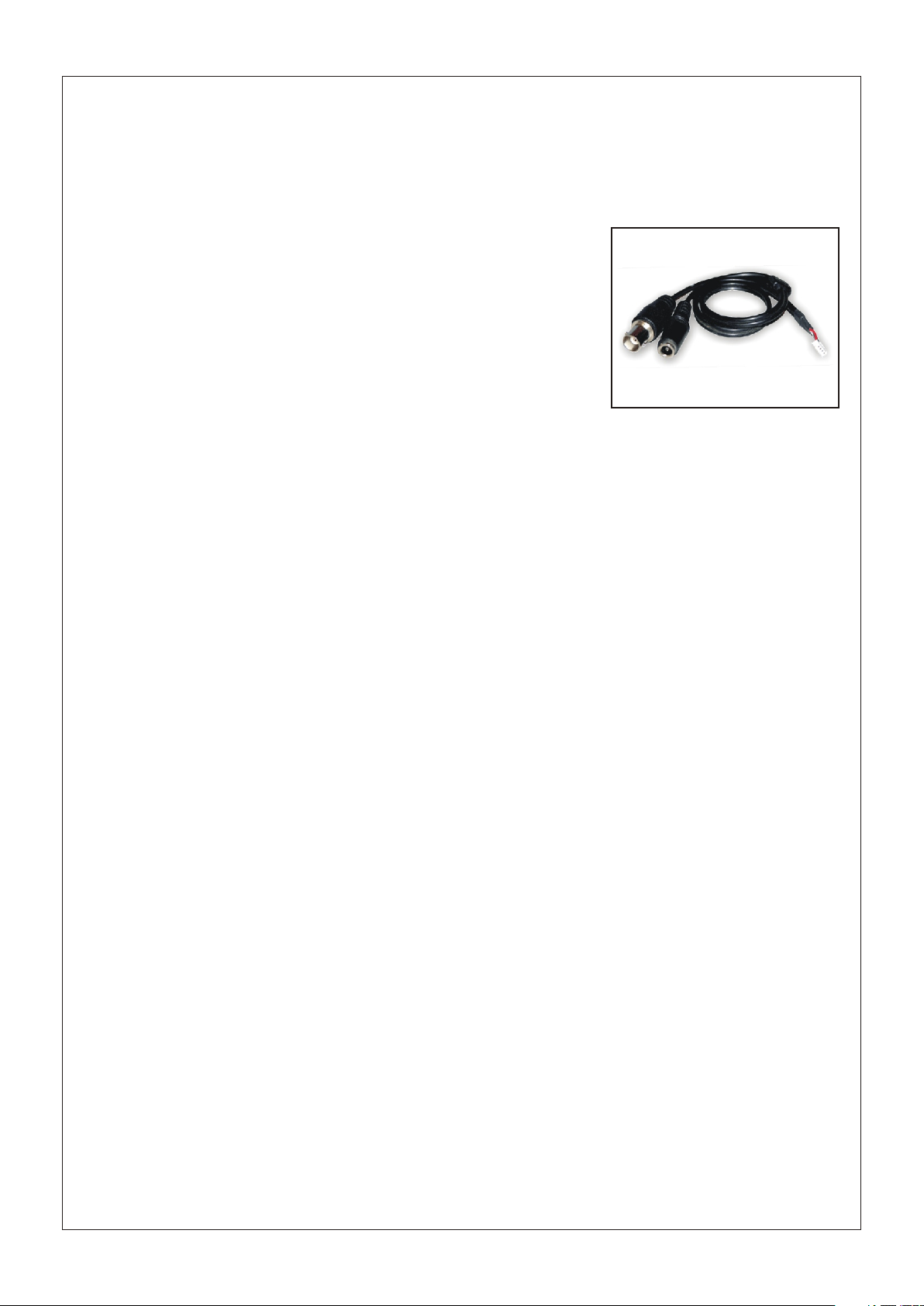
Video Output Connection
Use standard 75 Male BNC pin terminate with Co-axial video cable then connect to
camera video out BNC Female pin.
> Installation of Camera
Mounting Template Sticker: The mentioned technical drawing is for reference only.
Actual size of Mounting Template Sticker is matched with Dome Base. Stick Mounting
Template Sticker supplied for drilling the mounting hole on the mounting surface.
> Tips for Camera Location
1. Never expose the camera to direct sunlight without additional camera housing. Keep
sufficient distance to direct heat sources.
2. Never install the camera at humid, oily or dusty locations without using an additional
housing. (Without additional housing the camera is not suitable for outdoor use)
3. Do not aim the camera towards indoor lighting, the windows, the sunlight or the sky.
(To get good pictures, camera and light should be aimed towards the object)
4. Avoid peak light as background (Also caused by reflection)
Page 4

> Dimension
230mm
80mm
140mm
Page 5

3. Operation Guide :
> Menu Structure
LENS
BLC
E. SHUTTER
R-Y GAIN
WB MODE
AGC
WDR
SENSE_UP
B-Y GAIN
C-SUP
D&N MODE
MIRROR
A-SUP
GAMMA
SHARPNESS
MOTION
SET WINDOW
NEGA
FREEZE
ALL SET
MASK 1
3_DNR
SENSITI
ALL CLEAR
MASK 2
MASK 3
D_ZOOM
SLC
SHOW NDI
DELAY OUT
MASK 5
MASK 4
DIS
HME
DPC
TITLE
CAMERA ID
MASK 6
SYNC MODE
MONITOR
V_PHASE
BAUDRATE
LANGUAGE
EXIT
OMNI LENS
SAVE & EXIT
FACTORY SET
EXPOSURE
COLOR
DAY&NIGHT
FUNCTION
MOTION
OSD MANU
Page 6
PRIVACY
SYNC
SETUP
EXIT

> Function Description
1 Exposure:
Lens : 2 mode DC and Manual with set brightness level
from 0 to 100.
Shutter : 4 Mode - FLK, Fixed, Manual and Auto.
1/100 or 1/120 @ FLK
1/50,1/250,1/500, 1/1000, 1/2000, 1/4000,
1/10000, 1/100000 @ Fixed
BLC (Back Light Compensation) : OFF/ ON with adjust in 5 zone
WDR (Wide Dynamic Range) : OFF/ ON with adjust level range from 0 ~ 10
AGC (Auto Gain Control) : 4 level High, Middle, Low, OFF
SENS UP : OFF/ Auto, adjust with range of X2 ~ X256
2.Color :
W/B Mode : ATW, AWC, Manual
R-Y Gain : Can be set level from 0 ~ 255.
B-Y Gain : Can be set level from 0 ~ 255.
3.Day Night :
D & N Mode : 3 level Auto, Color, B/W
C_SUP (Color Suppression) : Can be set level from 0 ~ 15
A_SUP (Aperture Suppression) : Can be set level from 0 ~ 15
This two above function is used under low light condition. Using these functions you
can get image without noise.
Page 7

4.Function :
Mirror : 4 Mode OFF, Mirror, V-Flip, Rotate
Sharpness : Can be set level from 0 ~ 15
Gamma : 3 Level 0.45, 0.6, 1
Freeze : ON/OFF
Negative Image : ON/OFF
D-Zoom : OFF/ON with adjust with X1.0 to X3.0
3- DNR : four level Off, Low, Middle, High
SLC (Side Light Compensation) : Can be set level from 0 ~ 50
HME : Can be set level from 0 ~ 50
DIS (Digital Image Stabilizer) : ON/OFF
5.Motion : OFF/ON with 16 X 15 selectable zone with
sensitivity level from 0 ~99
6.Privacy Masking : OFF/ON with 6 selectable zone
7.Sync : 2 mode Inter, Auto
8.Setup:
Camera ID : Can be set range from 0 ~ 255
Title Edit : A ~ Z, 0 ~ 9, can set position also
Monitor : 2 mode CRT, LCD
DPC SET (Dead Pixel Cancellation): Can be set white and black level.
This function is used for takes off the dead pixel
Baud rate : can be set diff baud rate like 2400, 4800, 9600,
14400, 19200
9.Exit
Page 8

3. Technical Specification
Model Number
Video
CCD
Lens
Effective Pixel
Horizontal Resolution
Min. Illumination@Day
Min. Illumination@Night
Scanning Frequency (H)
Scanning Frequency (V)
Gamma
S/N Ratio
Video Output
Sync System
Operational
ERN-LWG3065N/P ERN-LWG4065N/P
1/3" SONY Super HAD II Double Scan CCD
6 to 50mm DC Auto IRIS
NTST : 768 x 494, PAL : 752 x 582
650 TVL
0.8 Lux at Day(Cut Off)
0.08 Lux At Night(IR LED On)
NTSC : 15.734KHz, PAL : 15.625KHz
NTSC : 59.94KHz, PAL : 50Hz
0.45 Adjustable
50dB
1V p-p, 75
2:1 Internal
Lens
Exposure Mode
Shutter Speed
AGC
BLC
D-WDR
SENS-UP
3-DNR
Freeze
Day/Night Mode
Mirror
Motion Detection
Privacy Masking
DC IRIS / Manual
Auto/Manual/FLK
AUTO
FLK 1/120
Fixed 1/60~1/100,000sec
ON/OFF
ON/OFF
ON/OFF
2,4,8,16,32,64,128,256
High/Middle/Low/OFF
ON/OFF
Auto/Color/B/W
OFF/Mirror/V-Flip/Rotate
On /Off, Supports up to 16*15 Zone
On /Off, Supports up to 6 Zone
AUTO
FLK 1/100
Fixed 1/50~1/100,000sec
Digital Image Stabilizer
Digital Zoom
SLC
Monitor Option
ON/OFF
3X
ON/OFF
CRT/LCD
Page 9

Color Control
Contrast, Sharpness, Hue, saturation
Camera Name
White Balance
Night Vision
IR LED
Number of LED
Diameter
IR Wave Length
IR Distance
Electrical
Power Supply
Current Consumption
IR Consumption
Environmental
Operating Temperature
Humidity
Yes, A to Z, 0 to 9, & etc
ATW / AWB / MANUAl / FIXED
Giant IR Normal IR Giant IR Normal IR
8 24 16 24
ǿ0.8 ǿ0.8
ǿ0.5
ǿ0.5
850nM
20 ~ 25 Meter 40 ~ 45 Meter
12V DC Standard ±10%
175mA
2Amp
-10°C ~ 50°C
95%
Protection Class
Dimensional
Housing
Weight
Dimension
IP 66
Outdoor Wall Mount with Cable Managed Bracket
875g
230(L) x 140(H) x 80(W) mm
Page 10

4. Troubleshooting
Error Cause
No Picture Check supply voltage, check power cable and video cable
The picture is noisy Insufficient light (Properly adjusted to the camera)
The picture is too bright Too much peak light, change camera location or active back
. light function of the camera
The picture is not sharp Lens focus not adjusted properly
The picture is distorted Different GND potentials between camera and monitor (Bad
connection)
Ghost Image Wrong 75 termination, shield of video cable interrupted.
5. Cleaning and Care
-Before you start to clean the camera body, disconnect the unit from power supply.
-For reasons of electrical safety never clean the camera with water or other liquid
matters and never put the camera under water.
-To clean use a soft dry cloth. Cleaning the camera inside is strictly forbidden and may
only be done by your authorized dealer.
-Since all camera functions are self adjusting and the camera does not contain any
parts or components that are subject to wear. We advice you not to open the camera
(except for the flap for settings), unless the camera appears to be defective.
Page 11

6. Maintenance and Support
1. How to request after-sale service?
When ever you want to send repairing material back to us kindly use
the same Channel where u purchased the material must with Return Material
Authorization (RMA) Form download from our website.
http://www.eyerisdigital.com/RMA%20Form.pdf
2. Following cases should be paid even within the warranty period.
A)When defects are caused by the careless handling of the user.
B)When improper or unauthorized repairs are done or when the inside is modified or
damaged.
C)Defects caused by natural disaster or power problem.
Technical Support: For any type of product operating, Function, Installation related
queries or want to know more about our product details specification or function,
contact our website or E-mail to us.
http://www.eyerisdigital.com/support.html
www.eyerisdigital.com
Page 12
 Loading...