

Eyemax PT TP 950 Series Instruction Manual

INSTRUCTION MANUAL Ver 1. 1
Mini Speed Dome Camera / PT TP 950 Series
F
MV-N10T-D NTSC DC 12V
F
MV-P10T-D PAL DC 12V
F
MV-N10T-A NTSC AC 24V
F
MV-P10T-A PAL AC 24V

This lightning flash with arrowhead symbol is intended to alert the user to the
presence of un-insulated "dangerous voltage" within the product's enclosure that
may be of sufficient magnitude to constitute a risk of electric shock to persons.
This exclamation point symbol is intended to alert the user to the presence of
important operating and maintenance (servicing) instructions in the literature
accompanying the appliance.
Speed Dome Camera Instruction Manual
2/38

NOTICENOTICENOTICENOTICENOTICENOTICENOTICENOTICENOTICENOTICENOTICENOTICENOTICENOTICENOTICENOTICENOTICE
Important Safeguard
1. Read Instructions
Read all of the safety and operating instructions before using the product.
2. Retain Instructions
Save these instructions for future reference.
3. Attachments / Accessories
Do not use attachments or accessories unless recommended by the appliance manufacturer as they may
cause hazards, damage product and void warranty.
4. Water and Moisture
Do not use this product near water or moisture.
5. Installation
Do not place or mount this product in or on an unstable or improperly supported location. Improperly
installed product may fall, causing serious injury to a child or adult, and damage to the product. Use only
with a mounting device recommended by the manufacturer, or sold with the product. To insure proper
mounting, follow the manufacturer's instructions and use only mounting accessories recommended by
manufacturer.
6. Power source
This product should be operated only from the type of power source indicated on the marking label.
Precautions
Operating
z Before using, make sure power supply and others are properly connected.
z While operating, if any abnormal condition or malfunction is observed, stop using the camera
immediately and then contact your local dealer.
Handling
z Do not disassemble or tamper with parts inside the camera.
z Do not drop or subject the camera to shock and vibration as this can damage camera.
z Care must be taken when you clean the clear dome cover. Especially, scratch and dust will ruin your
quality of camera.
Installation and Storage
z Do not install the camera in areas of extreme temperature, which exceed the allowable range.
z Avoid installing in humid or dusty places.
z Avoid installing in places where radiation is present.
z Avoid installing in places where there are strong magnetic fields and electric signals.
z Avoid installing in places where the camera would be subject to strong vibrations.
z Never expose the camera to rain and water.
Speed Dome Camera Instruction Manual
3/38

1
○
Introduction
Features 5
Product & Accessories
Parts Name & Functions
2
○
Installation
DIP Switch Setup 10
Direct Installation on the Ceiling
Installation using Ceiling Mount Bracket 16
Installation using Wall Mount Bracket
Cabling
3
○
Operation
Checking Before Operation 20
Preset and Pattern Function Pre-Check
Start OSD Menu 21
Reserved Preset
Preset
Swing 22
Pattern
Group
Other Functions 25
OSD Display of Main Screen
4
○
How to use OSD Menu
General Rules of Menu Operation 27
Main Menu
Display Menu for Main Screen
Privacy Zone Mask Setup
Camera Module Setup
Motion Setup
Preset Setup
Swing Setup
Pattern Setup
Group Setup
System Initialize
○5 Specifications
Dimension
CONTENTS
7
8
13
17
18
20
21
22
23
24
26
27
28
29
30
38
40
43
44
45
47
48
51
Speed Dome Camera Instruction Manual
4/38

INTRODUCTION
Fe at u re s
Camera Specifications
z CCD Sensor : 1/4" Interline Transfer CCD
z Zoom Magnification : × 10 Optical Zoom, × 10 Digital Zoom (Max × 100 Zoom)
z Day & Night Function
z Various Focus Mode : Auto-Focus / Manual Focus / Semi-Auto Focus.
z Independent & Simultaneous Camera Characteristic Setup in Preset operation
Powerful Pan/Tilt Functions
z Max. 360°/sec high speed Pan/Tilt Motion
z Using Vector Drive Technology, Pan/Tilt motions are accomplished in a shortest path. As a result,
time to target view is reduced dramatically and the video on the monitor is very natural to watch.
1
z For jog operation using a controller, since ultra slow speed 0.05°/sec can be reached, it is very easy
to locate camera to desired target view. Additionally it is easy to move camera to a desired position
with zoom-proportional pan/tilt movement.
Preset, Pattern, Swing, Group, Privacy Mask and More…
z MAX. 127 Presets are assignable and characteristics of each preset can be set up independently,
such as White Balance, Auto Exposure, Label and so on.
z Max. 8 set of Swing action can be stored. This enables to move camera repetitively between two
preset positions with designated speed.
z Max. 4 of Patterns can be recorded and played back. This enables to move camera to follow any
trajectory operated by joystick as closely as possible.
z Max. 8 set of Group action can be stored. This enables to move camera repetitively with
combination of Preset or Pattern or Swing. A Group is composed of max. 20 entities of
Preset/Pattern/Swings.
z Privacy Masks are assignable, not to intrude on other’s privacy. (4 Privacy Zones)
PTZ(Pan/Tilt/Zoom) Control
z With RS-485 communication, max. 255 of cameras can be controlled at the same time.
z Pelco-D or Pelco-P protocol can be selected as a control protocol in the current version of firmware.
Speed Dome Camera Instruction Manual
5/38

OSD(On Screen Display) Menu
z OSD menu is provided to display the status of camera and to configure the functions interactively.
z The information such as Camera ID, Pan/Tilt Angle, Alarm Input and Preset can be displayed on
screen.
Alarm I/O Functions
z 4 alarm sensor Inputs are available.
z To reject external electric noise and shock perfectly, alarm sensor Input is decoupled with photo
coupler.
z The signal range of sensor input is from DC 5.0 to 12.0 volts to adopt various applications.
z If an external sensor is activated, camera can be set to move to the corresponding Preset position.
Reserved Presets for Special Purpose
INTRODUCTION
1
z Most camera characteristics can be set up easily and directly with reserved preset, not entering
into OSD menu. For more information, refer to “Reserved Preset” in this manual.
Speed Dome Camera Instruction Manual
6/38
Product & Accessories
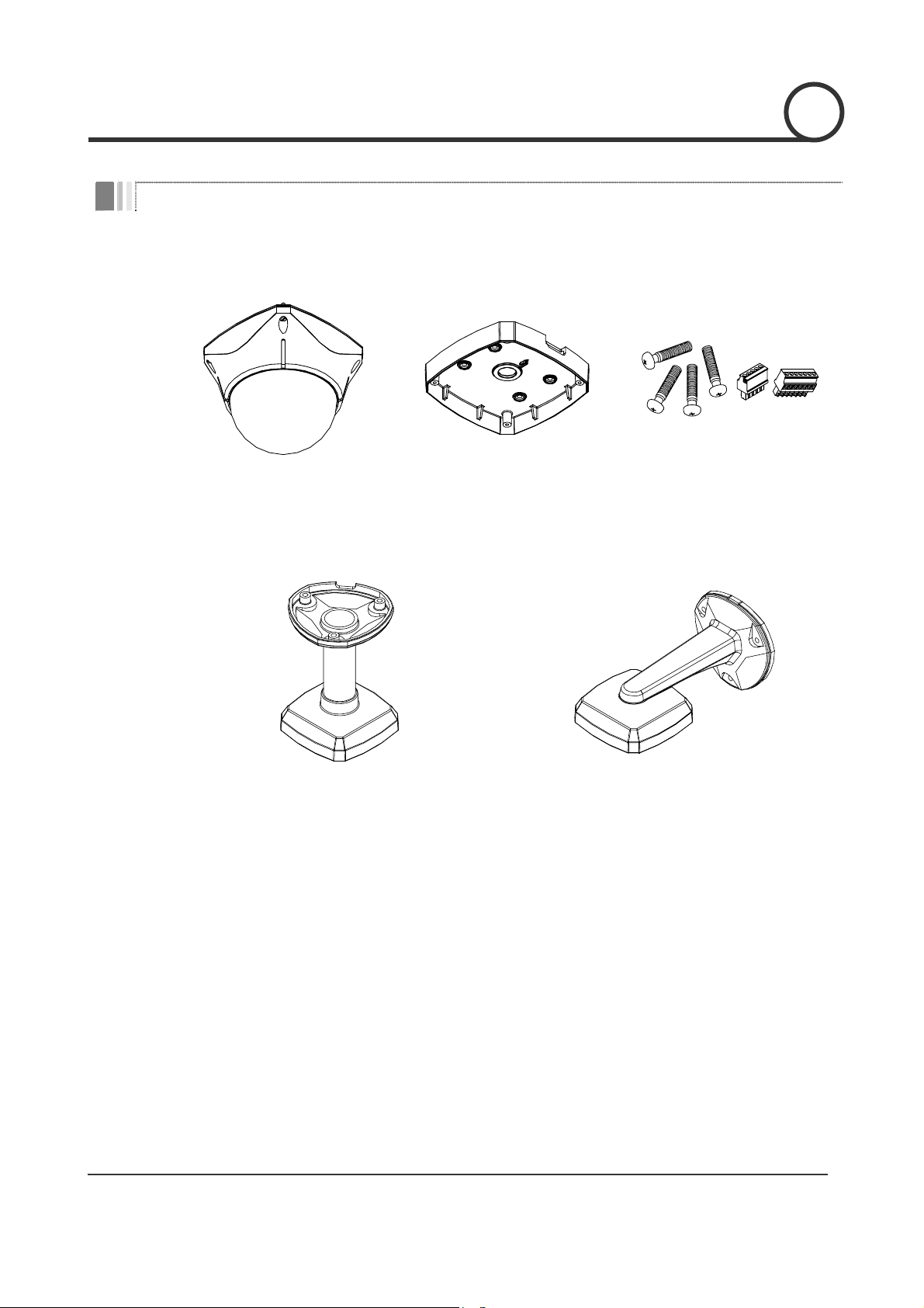
Product & Accessories
z Main Body z Surface Mount Bracket z Screws & Terminal Block
INTRODUCTION
1
Options
z Ceiling Mount Bracket z Wall Mount Bracket
Speed Dome Camera Instruction Manual
7/38
k
INTRODUCTION
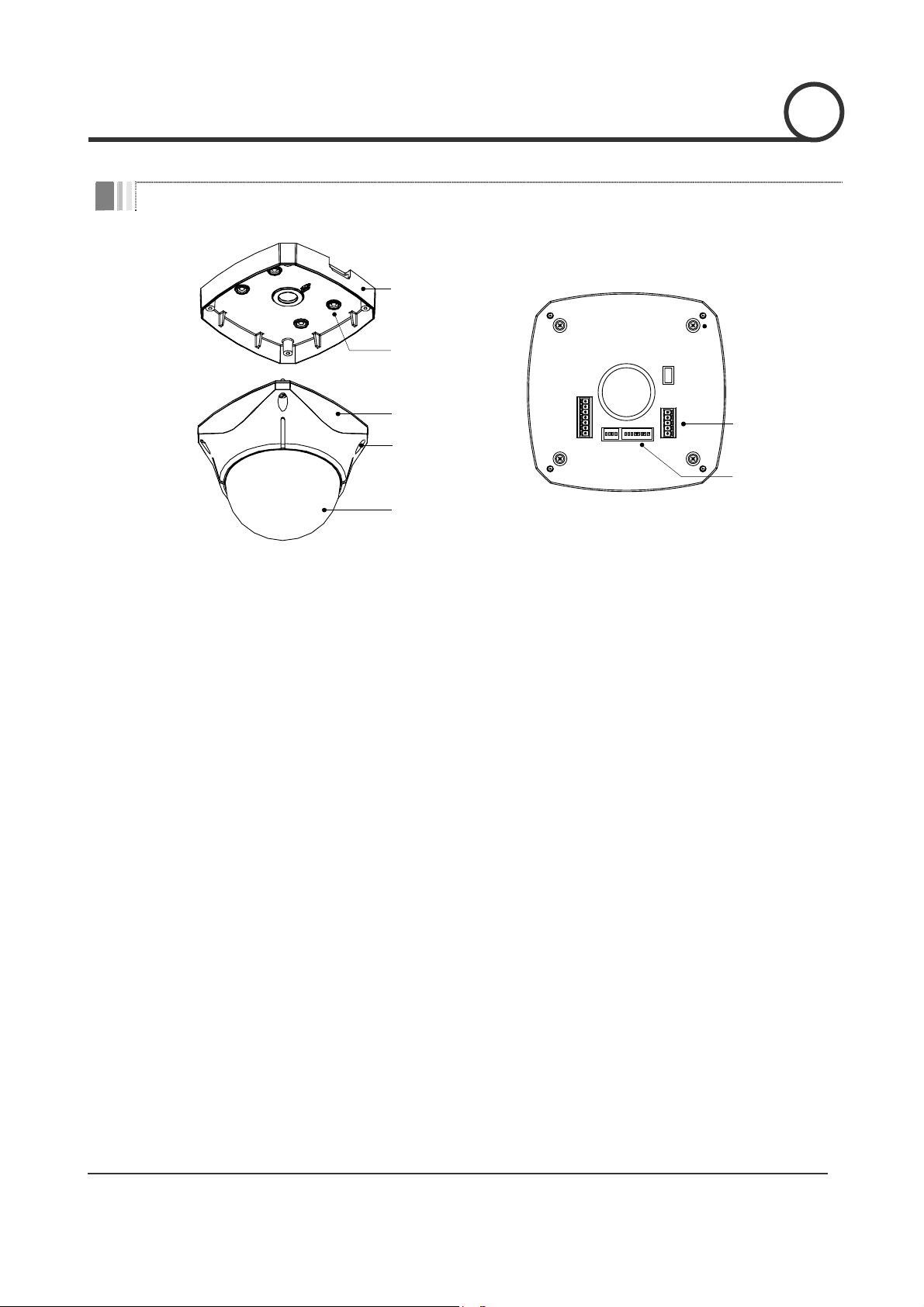
Parts Name & Functions
Surface
Mount Bracket
Mounting Hole
1
Main Body
Lockup Screw
)
OPTIONS
ADDRESS(ID
ON
Cabling
Terminal Bloc
DIP Switch
Dome Cover
z Main Unit / Surface Mount Bracket z Back of Main Unit
z Dome Cover Do not detach protection vinyl from dome cover before finishing all
installation process to protect dome cover from scratches or dust.
z Surface Mount Bracket This is used to install the camera directly on the ceiling. After
separating this cover first and then attach this directly to ceiling.
Camera must be assembled at the last stage.
Do not use this bracket when installing camera on the wall with wall
mount bracket or on the ceiling with ceiling mount bracket.
z Lockup Screw Fixes main unit to surface mount bracket.
z Cabling Terminal Block During installation, Power, Video, Communication, Alarm Input cables
are connected on to this cabling terminal block.
z DIP Switch Adjusts camera ID and protocols.
Speed Dome Camera Instruction Manual
8/38
n
INSTALLATION
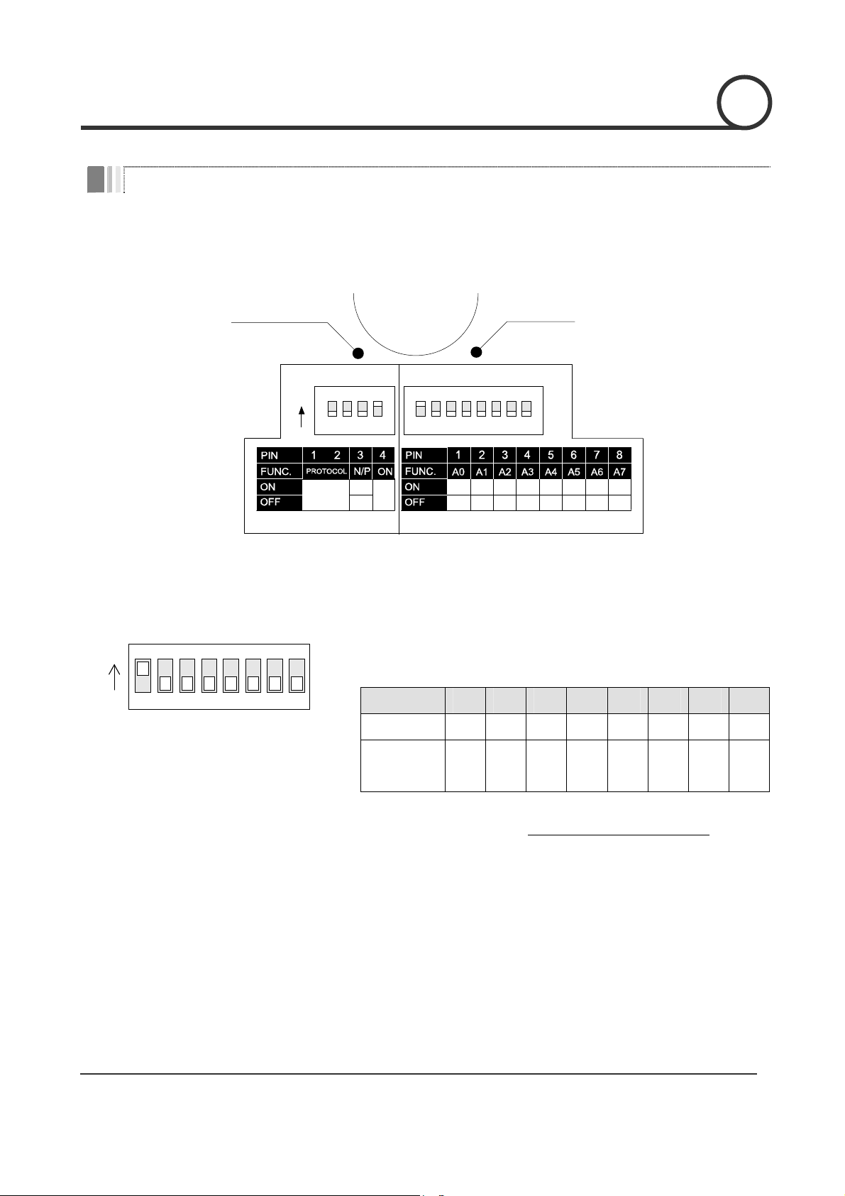
DIP Switch Setup
Before you install the camera, you should set the DIP switches to configure the camera ID, communication
protocol.
Communicatio
Protocol
Camera ID
2
Camera ID Setup
ON
ON
123456
ON
the Manual
78
OPTIONS
Refer to
PAL
NTSC
ADDRESS (ID)
1 2 4 8 16 32 64 128
00000000
z ID number of camera is set using binary number. The example is
shown bellow.
Pin 1 2 3 4 5 6 7 8
ID Value 1 2 4 8 16 32 64 128
ex) ID=5 on off on off off off off off
ex) ID=10 off on off on off off off off
Speed Dome Camera Instruction Manual
z The range of ID is 1~255. Do not use 0 as camera ID. Facto r y
default of Camera ID is 1.
z If you want to control a certain camera, you must match the camera
ID with Cam ID setting of DVR or Controller.
9/38
INSTALLATION
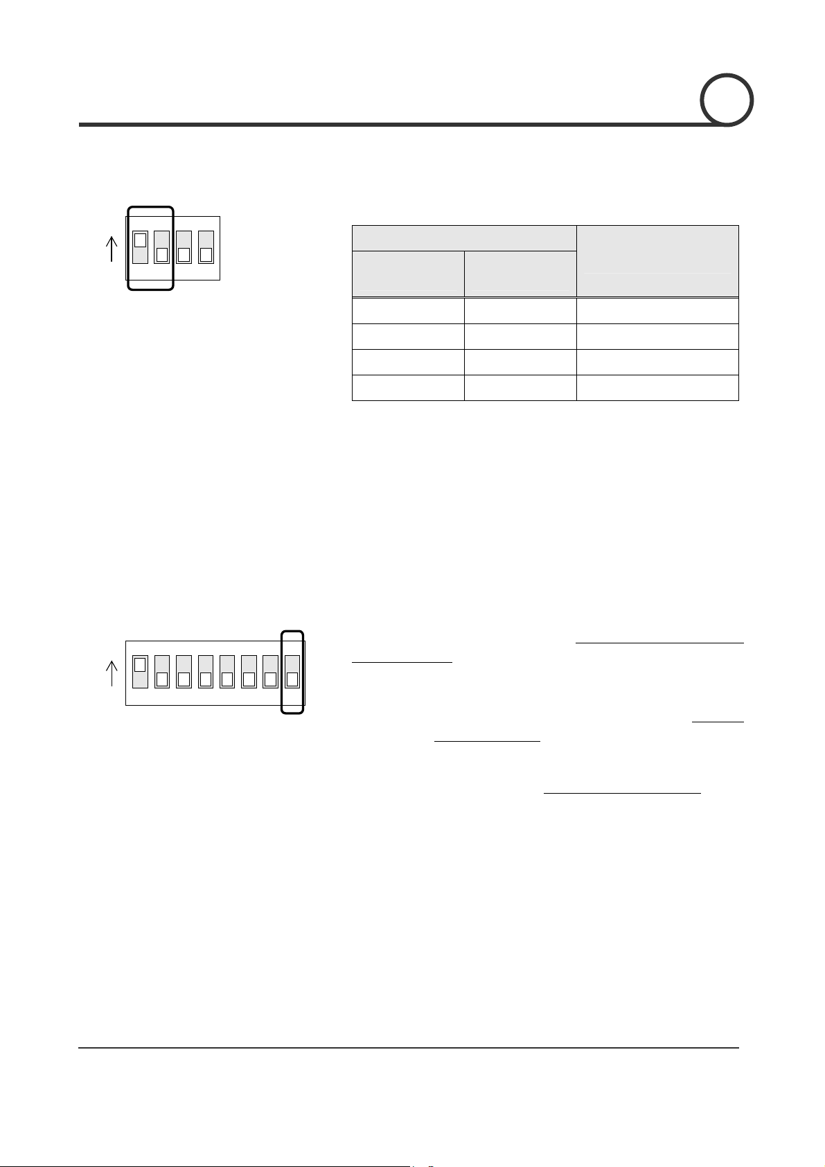
Communication Protocol Setup
ON
ON
1234
z Select the appropriate Protocol with DIP switch combination.
Switch State
P0
(Pin 1)
P1
(Pin 2)
Protocol
2
Reserved for Supplier
ON
ON
123456
78
OFF OFF PELCO-D, 2400 bps
ON OFF PELCO-D, 9600 bps
OFF ON PELCO-P, 4800 bps
ON ON PELCO-P, 9600 bps
z If you want to control using DVR or P/T controller, their protocol must
be identical to camera. Otherwise, you can not control the camera.
z If you changed camera protocol by changing DIP S/W, the change
will be effective after you reboot the camera.
z Factory default of protocol is “Pelco-D, 2400 bps”.
z Since Pin 3 ~ Pin 4 is only for supplier, DO NOT CHANGE THESE ITS
ORIGINAL STATE. If you change one of these, proper operation can
not be achieved.
~ Pin 3 PAL / NTSC system selection of Camera. DO NOT
CHANGE THIS PIN.
Speed Dome Camera Instruction Manual
~ Pin 4 Factory default is ON state. This pin is used for system
firmware upgrade. DO NOT CHANGE THIS PIN
.
10/38
INSTALLATION
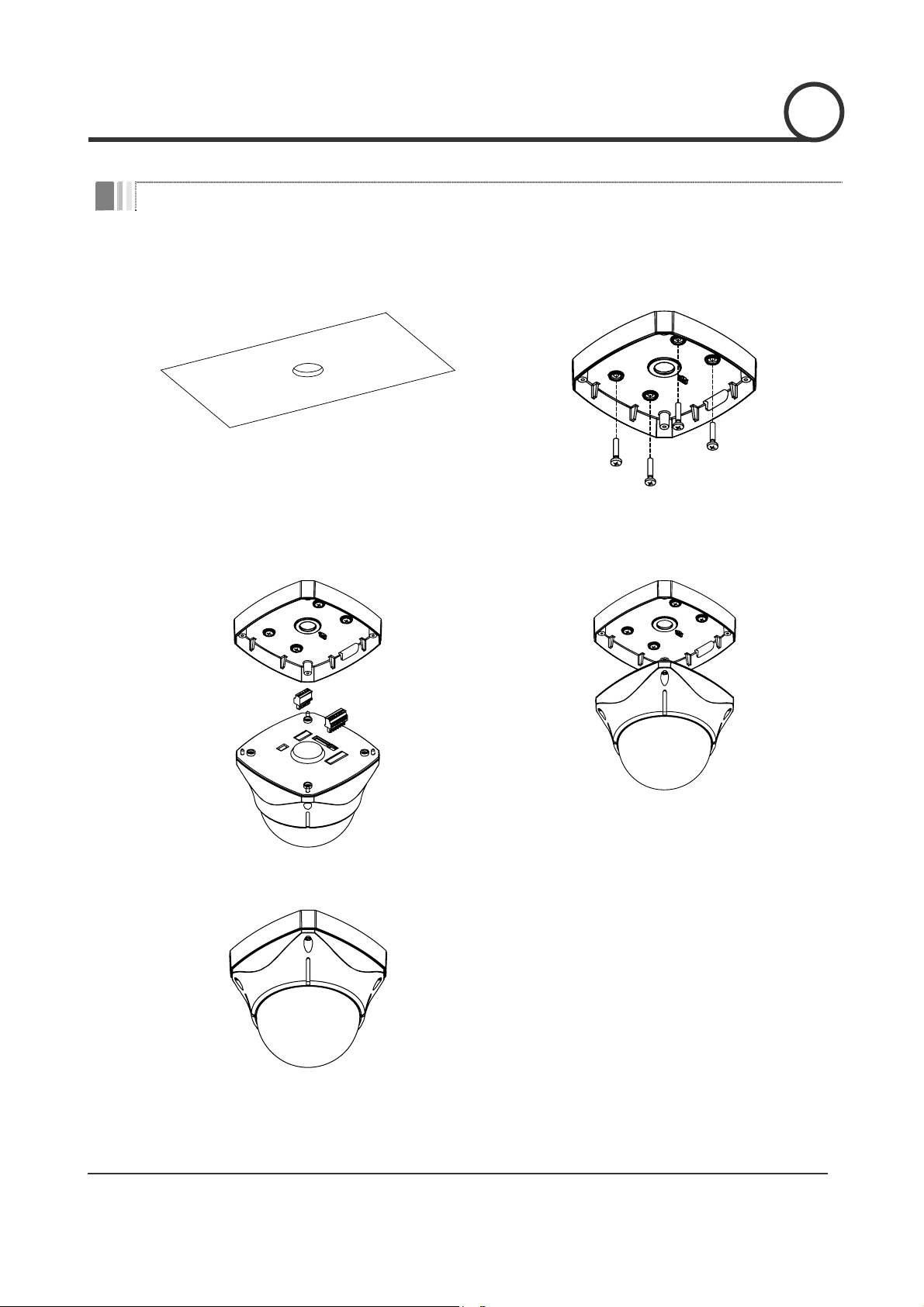
Direct Installation on the Ceiling
① To pass cables to upside of ceiling, please, make
about 50~60mm hole on the ceiling panel.
③ Wire cables to terminal block and connect the
terminal blocks to main unit.
② Screw surface mount bracket to ceiling with 4
screws.
④ Screw main unit to surface mount bracket with 4
lock-up screws.
2
⑤ Detach protection vinyl from dome cover.
Speed Dome Camera Instruction Manual
11/38
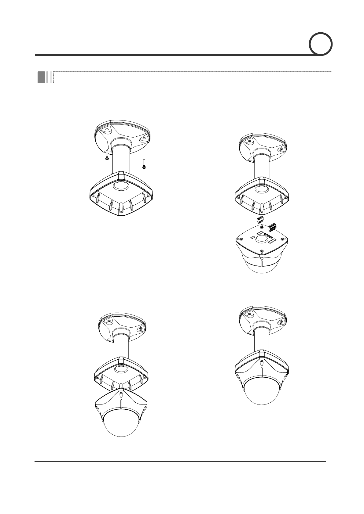
Installation using Ceiling Mount Bracket
① Screw ceiling mount bracket to ceiling with 3
screws.
② Wire cables to terminals and connect the
terminals to main unit. Do not use surface mount
bracket!
INSTALLATION
2
③ Screw main unit to ceiling mount bracket with 4
screws.
④ Detach protection vinyl from dome cover.
Speed Dome Camera Instruction Manual
12/38
 Loading...