

Eyemax PT-9630, PT-9637, PT-9736 Instruction Manual

INSTRUCTION MANUAL Ver 1.01
ANTI-VANDAL 30x, 36x, 37x SPEED DOME CAMERA
432
432432
5.7
5.75.7
PRESET 127
PRESET 127
PRESET 127
AUTO PAN 8
SCAN 8
AUTO PAN 8AUTO PAN 8
127
127
127
SCAN 8SCAN 8
4
44
42
42
SCHEDULE
SCHEDULESCHEDULE

E
This lightning flash with arrowhead symbol is intended to alert the user
to the presence of un-insulated "dangerous voltage" within the product's
enclosure that may be of sufficient magnitude to constitute a risk of
electric shock to persons.
This exclamation point symbol is intended to alert the user to the
presence of important operating and maintenance (servicing) instructions
in the literature accompanying the appliance.
WARNING: TO PREVENT THE RISK OF FIRE OR ELECTRIC SHOCK HAZARD,
DO NOT EXPOSE ELECTRONICS TO RAIN OR MOISTURE
Before installing and using the camera, please read these instructions
thoroughly and retain them for later reference
ANTI-VANDAL 30x, 36x, 37x SPEED DOM
2/46
E
NOTICE
1. Read Instructions
Read all of the safety and operating instructions before using the product.
2. Retain Instructions
Save these instructions for future reference.
3. Attachments / Accessories
Do not use attachments or accessories unless recommended by the appliance manufacturer as
they may cause hazards, damage product and void warranty.
4. Water and Moisture
Do not use this product near water or moisture.
5. Installation
Do not place or mount this product in or on an unstable or improperly supported location.
Improperly installed product may fall, causing serious injury to a child or adult, and damage to
the product. Use only with a mounting device recommended by the manufacturer, or sold with
the product. To insure proper mounting, follow the manufacturer's instructions and use only
mounting accessories recommended by manufacturer.
6. Power source
This product should be operated only from the type of power source indicated on the marking
label.
Important Safeguard
Operating
z Before using, make sure power supply and others are properly connected.
z While operating, if any abnormal condition or malfunction is observed, stop using the
Handling
z Do not disassemble or tamper with parts inside the camera.
z Do not drop or subject the camera to shock and vibration as this can damage camera.
z Care must be taken when you clean the clear dome cover. Especially, scratch and dust will
Installation and Storage
z Do not install the camera in areas of extreme temperature, which exceed the allowable
z Avoid installing in humid or dusty places.
z Avoid installing in places where radiation is present.
z Avoid installing in places where there are strong magnetic fields and electric signals.
z Avoid installing in places where the camera would be subject to strong vibrations.
z Never expose the camera to rain and water.
NOTE: If the camera is installed or rebooted after power failure when ambient temperature is
below the freezing point, the dome cover is frosted. In this case, the frost will be disappeared
Precautions
camera immediately and then contact your Special dealer.
ruin your quality of camera.
range.
ANTI-VANDAL 30x, 36x, 37x SPEED DOM
3/46

E
after 3 hours after turning on the power. (It is noted that lowest guaranteed operating
temperature is -45℃ (-49℉) without wind.)
ANTI-VANDAL 30x, 36x, 37x SPEED DOM
4/46

E
CONTENTS
1
○
Introduction
Features
Product & Accessories
Parts Name & Functions
2
○
Installation
DIP Switch Setup
Installation using Wall Mount Bracket
Cabling
3
○
Operation
Checking Before Operation
Preset and Pattern Function Pre-Check
Start OSD Menu
Reserved Preset
Preset
Scan
Pattern
Group
Schedule
Other Functions
OSD Display of Main Screen
5
7
8
9
1
1
1
4
1
6
1
6
1
7
1
7
1
8
1
8
1
9
2
0
2
1
2
2
2
3
ANTI-VANDAL 30x, 36x, 37x SPEED DOM
4
○
How to use OSD Menu
General Rules of Menu Operation
Main Menu
System Information
Display Setup
Privacy Zone Mask Setup
Motion Setup
Function Setup
Preset Setup
2
4
2
4
2
5
2
5
2
6
2
7
2
9
3
5/46

E
Scan Setup
Pattern Setup
Group Setup
Schedule Setup
Camera Setup
System Setup
System Initialize
INTRODUCTION
○5 Specifications
Specifications
Dimension
0
3
2
3
3
3
4
3
6
3
7
4
0
4
2
4
3
4
6
1
Camera Specifications
Powerful Pan/Tilt Functions
Features
z CCD Sensor :
CCD
30x 1/4" Interline Transfer CCD
36x 1/4" EX-view HADTM CCD
37x 1/4" Double Density Interline Transfer CCD
z Zoom Magnification :
Optical Zoom Digital Zoom Total
30x 30 10 Max. 300
36x 36 12 Max. 432
37x 37 12 Max. 444
z WDR(Wide Dynamic Range) function support. (36x, 37x Only)
z DIS (Digital Image Stabilizer) function support. (37x Only)
z Day & Night Function : ICR(IR Cut filter Removal)
z Various Focus Mode: Auto Focus / Manual Focus / Semi-Auto Focus.
z Independent or Global camera settings for each Preset locations.
z Max. 360°/sec high speed Pan/Tilt Motion
z Using Vector Drive Technology, Pan/Tilt motions are accomplished in the shortest path.
As a result, time to target view is reduced dramatically and the video on the monitor is
ANTI-VANDAL 30x, 36x, 37x SPEED DOM
6/46

E
very natural to watch.
z Ultra low speed (0.05°/sec) enables operator to locate camera to desired target view with
accuracy and ease.
z Zoom-proportional pan/tilt speed helps operator to move the camera easily.
Preset, Pattern, Scan, Group, Privacy Mask, Schedule and More…
z MAX. 127 Presets are assignable. All of them have independent characteristics such as
White Balance, Auto Exposure, Label, Alarm Input/Output and so on.
z Max. 8 set of Scan can be stored. This enables to move camera repetitively between two
preset positions with designated speed.
z Max. 4 of Patterns can be recorded and played back. This enables to move camera to
follow any trajectory operated by joystick as closely as possible.
z Max. 8 set of Group action can be stored. This enables to move camera repetitively with
combination of Preset or Pattern or Scan. A Group is composed of max. 20 entities of
Preset/Pattern/Scans.
z Max 8 Privacy Masks can be set up to protect privacy of other people.
z 7 rules of Schedule can be assigned by day and time. Appropriate actions (such as Home,
Preset, Group, Pattern and Scan) can be defined for each rule. Also, it is possible to use
Weekday and All days to simplify the rule.
PTZ(Pan/Tilt/Zoom) Control
z With RS-485 communication, max. 255 of cameras can be controlled at the same time.
z Pelco-D/ Pelco-P/ Samsung protocol can be selected as a control protocol in the current
version of firmware.
OSD(On Screen Display) Menu
z OSD menu is provided to display the status of camera and to configure the functions
interactively.
z The information such as Camera ID, Pan/Tilt/Zoom/Direction, Alarm Input & Output,
date/time, current temperature and Preset can be displayed on screen.
z Each display item can be turned on or off independently.
Alarm I/O Functions
z 8 alarm sensor Inputs and 4 relay output are available.
z To reject external electric noise and shock perfectly, alarm sensor Input is decoupled
with photo coupler.
z The signal range of sensor input is from DC 5.0 to 12.0 volts to adopt various
applications.
z If an external sensor is activated, camera can be set to move to the corresponding Preset
position.
z Relay outputs can be assigned to work with a certain preset.
INTRODUCTION
INTRODUCTION
1
1
ANTI-VANDAL 30x, 36x, 37x SPEED DOM
7/46

E
Reserved Presets for Special Purpose
z Most of camera settings are directly changed by calling Reserved Presets, not entering
into OSD menu. For more information, refer to “Reserved Presets” in page 18 of this
manual.
ANTI-VANDAL 30x, 36x, 37x SPEED DOM
8/46
E
INTRODUCTION
1
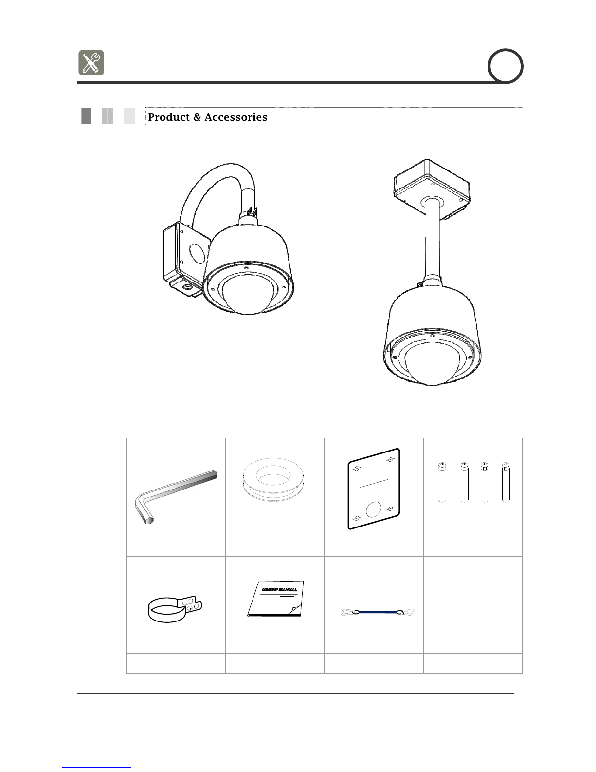
Product
Product & Accessories
z Wall Mount Type
z Ceiling Mount Type
Accessories
Hexagonal wrench Water proof tape Hole Template Anchor bolts (4pcs)
Housing Safety Cable
Hanger
Instruction Manual Safety Cable
ANTI-VANDAL 30x, 36x, 37x SPEED DOM
9/46
E
INTRODUCTION
1
FAN
HEATER
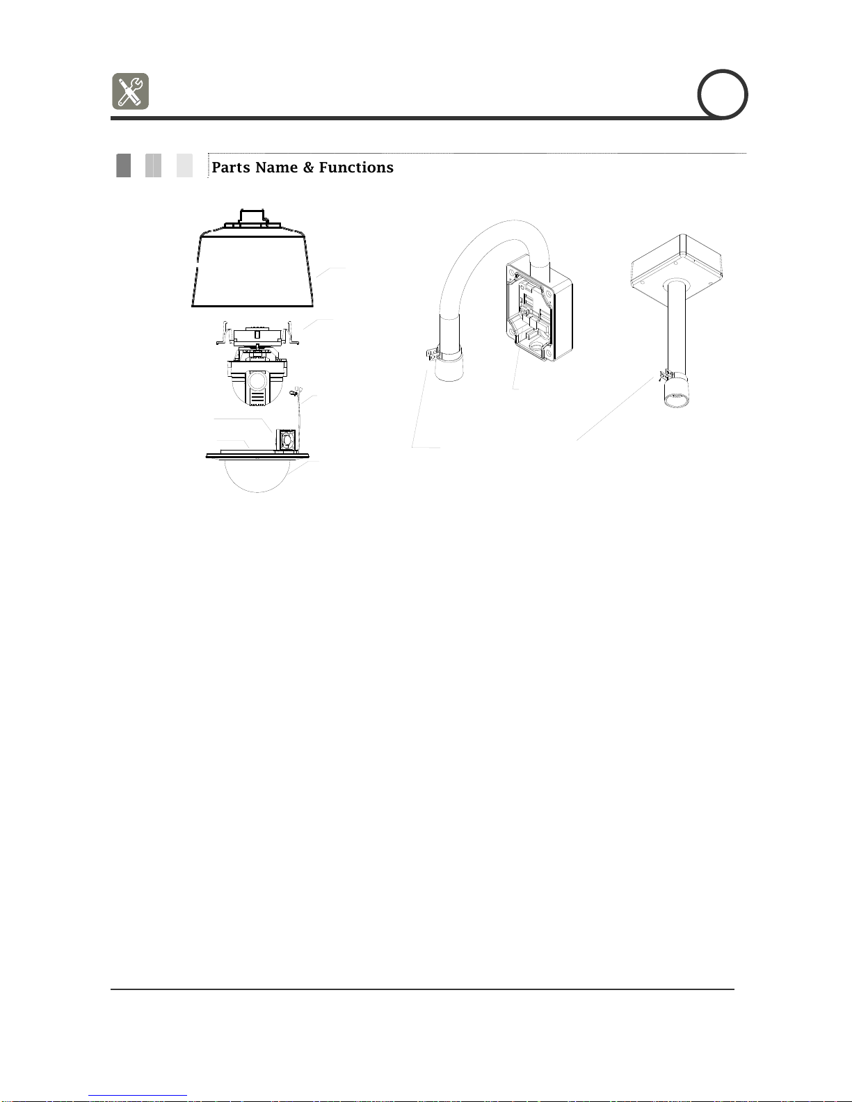
Parts Name & Functions
SUN SHIELD &
UPPER HOUSING
PTZ MECHANISM
DOME SAFETY CABLE
FAN/HEATER CABLE
DOME COVER
INNER BOX
HOUSING SAFETY CABLE
HANGER
z Dome Cover Do not detach protection vinyl from dome cover before
finishing all installation process to protect dome cover from
scratches or dust.
In the dome cover, there are Fan and Heater to remove moisture
on the bubble dome.
z Sunshield &
Upper housing
Sunshield protect bubble dome cover from the sun rays and
rain fall from. In the sunshield, there is the upper housing
which will contain accommodate PTZ mechanism. Also, the
upper housing will be connected to both mounting brackets and
dome cover.
z Wall/Ceiling mount
Bracket
These are used to install the camera on the wall or ceiling and
have junction box. The junction box of the bracket
accommodate inner box.
z Inner box The inner has many important roles of connection box between
camera and outside. Top of the box, there are dip switches and
terminal blocks for Power supply, Video, Communication, Alarm
Input/output.
ANTI-VANDAL 30x, 36x, 37x SPEED DOM
10/46
E
INSTALLATION
2
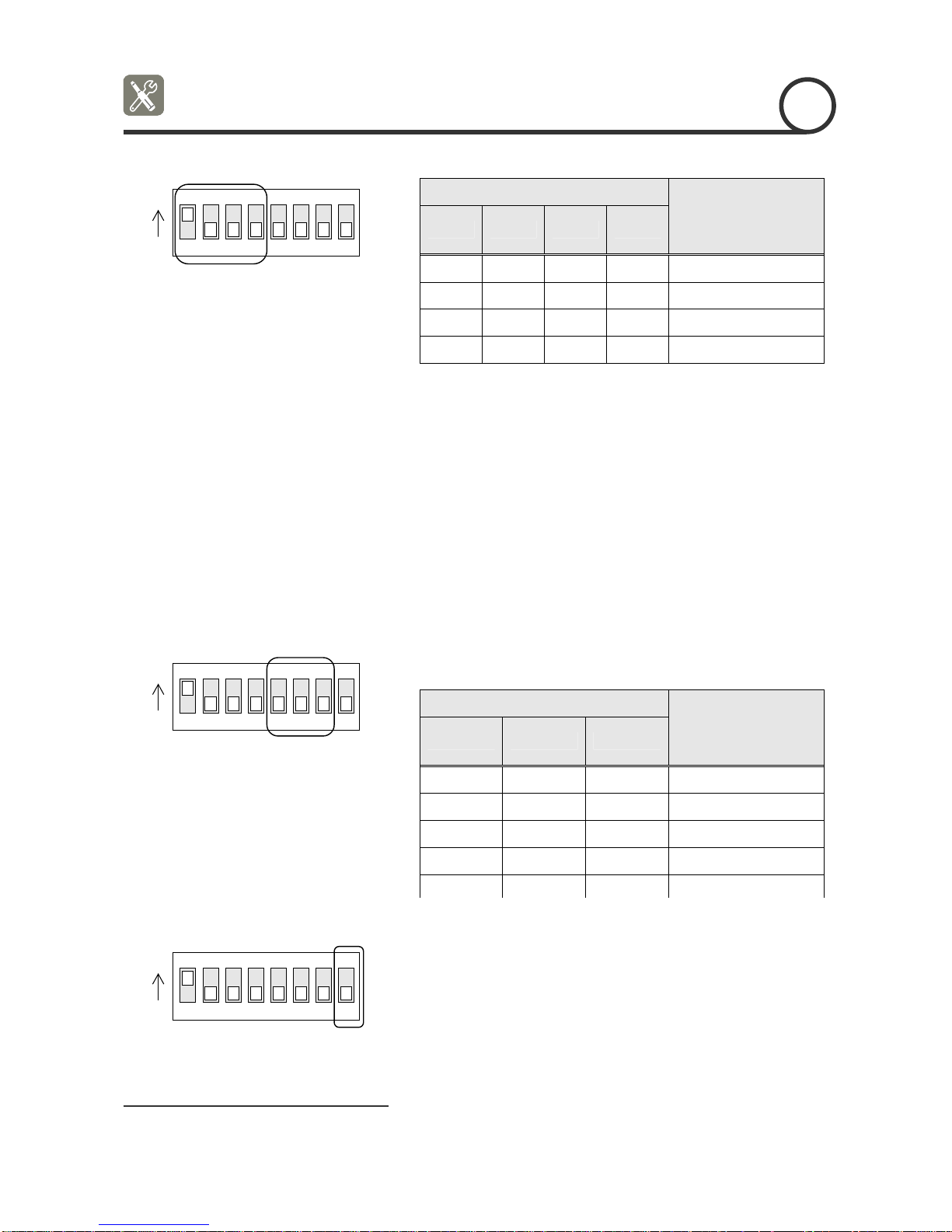
DIP Switch Setup
Before you install the camera, you should set the DIP switches to configure the camera ID,
communication protocol.
Protocol
0x00 : Auto Select
0x01 : Pelco-D
0x02 : Pelco-P
0x03 : SAMSUNG
0x04 : VCLTP
0x05 : KD6
ID Setting (1~255)
Buad Rate
0x00 : 2400
0x01 : 4800
0x02 : 9600
0x03 : 19200
0x04 : 38400
RS-485
Terminate
Camera ID Setup
ON
ON
123456
78
z ID number of camera is set using binary number. The
example is shown bellow.
Pin 1 2 3 4 5 6 7 8
ID Value 1 2 4 8 16 32 64 128
ex) ID=5 on off on off off off off off
ex) ID=10 off on off on off off off off
z The range of ID is 0~255. Factory default of Camera ID is 1.
z If you want to control a certain camera, you must match the
camera ID with Cam ID setting of DVR or Controller.
ANTI-VANDAL 30x, 36x, 37x SPEED DOM
11/46
E
INSTALLATION
2
Communication Protocol Setup
ON
ON
123456
78
Communication Baud rate Setup
ON
ON
z Select the appropriate Protocol with DIP switch combination.
Switch State
Protocol
Pin1 Pin2 Pin3 Pin4
OFF OFF OFF OFF Auto Protocol
ON OFF OFF OFF PELCO-D
OFF ON OFF OFF PELCO-P
ON ON OFF OFF SAMSUNG
z If you set the protocol as Auto Protocol, camera will
automatically recognize the kind of Protocol.
z Auto Protocol supports Pelco-D and Samsung Protocol.
z If you want to control using DVR or system keyboard, their
protocol must be identical to camera. Otherwise, you can not
control the camera.
z If you changed camera protocol by changing DIP S/W, the
change will be effective after you reboot the camera.
z Factory default of protocol is “Auto Protocol”
z Select the appropriate Baud rate with DIP switch
combination.
123456
78
RS-485 Termination Resistor
ON
ON
123456
78
z Pin 8 is used for ON/OFF of RS-485 Termination. Normally, it
must be OFF state. Especially when you have trouble with long
Daisy chain style connection, turn ON this termination switch
of last camera.
ANTI-VANDAL 30x, 36x, 37x SPEED DOM
Switch State
Protocol
Pin5 Pin6 Pin7
OFF OFF OFF 2400 BPS
ON OFF OFF 4800 BPS
OFF ON OFF 9600 BPS
ON ON OFF 19200 BPS
OFF OFF ON 38400 BPS
~ Pin 8 RS-485 Termination Resistor (On/Off)
12/46
E
INSTALLATION
2
Installation using Wall Mount Bracket
① Using the paper template, mark the holes on
the wall.
③ After locating the wall mount bracket on the
anchor bolts properly. Tighten the nuts for
anchor bolts
② After drilling the holes, fix the four anchor
bolts into the holes.
④ Connect cables to terminal blocks and BNC
in the inner box of junction box. See the
cabling in the next section.
ANTI-VANDAL 30x, 36x, 37x SPEED DOM
13/46
E
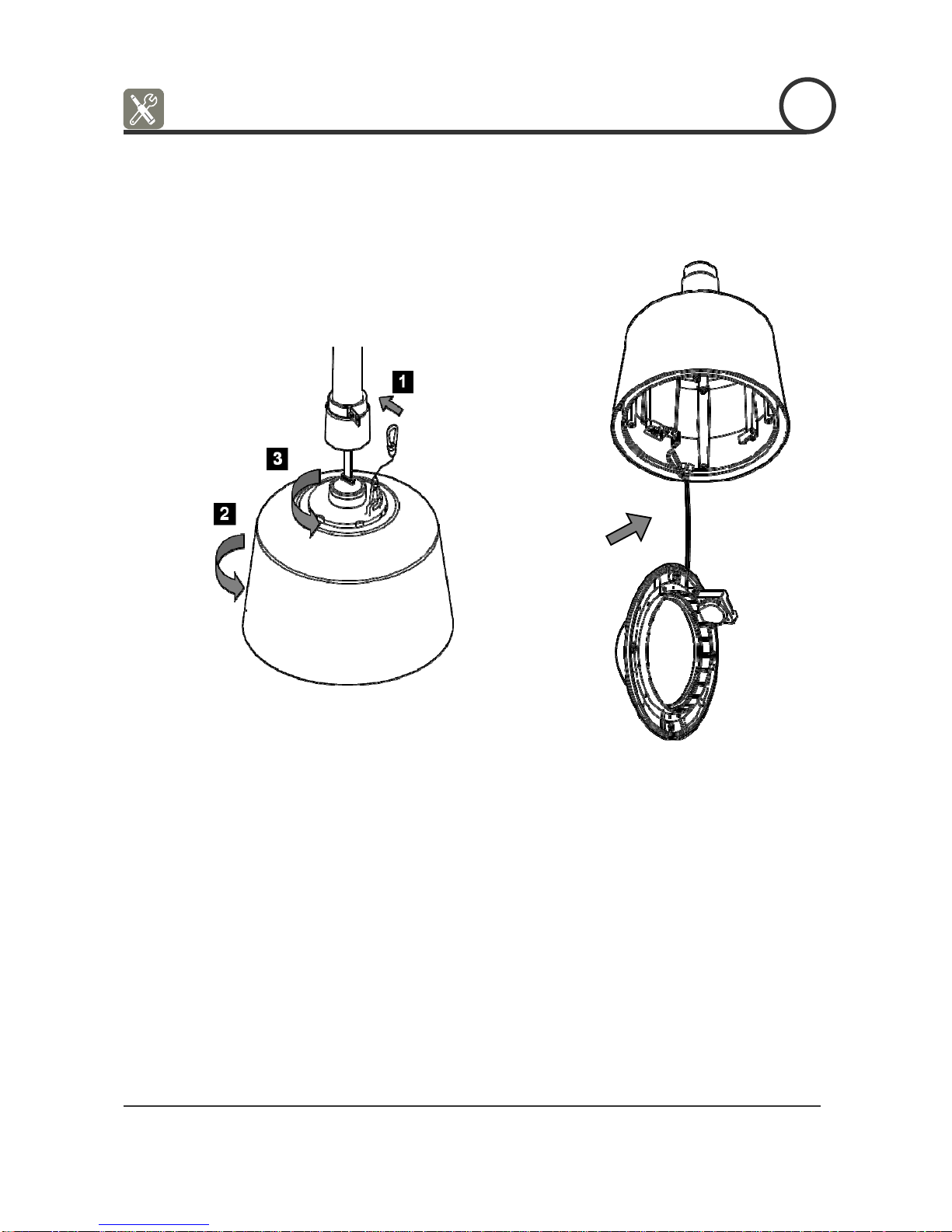
2
⑤ After hooking the safety cable on the hole
of pipe [1], attach the upper housing to wall
mount bracket by turning it at least seven
turns [2]. To fix the upper body orientation,
turn the handle of double nuts to clockwise
tightly [3].
⑥ Open the dome cover to install the PTZ
camera mechanism. Care must be taken
dome cover is hung by internal safety cable
properly. Plug fan/heater cables into the
connectors in the housing.
ANTI-VANDAL 30x, 36x, 37x SPEED DOM
14/46
E
INSTALLATION
2
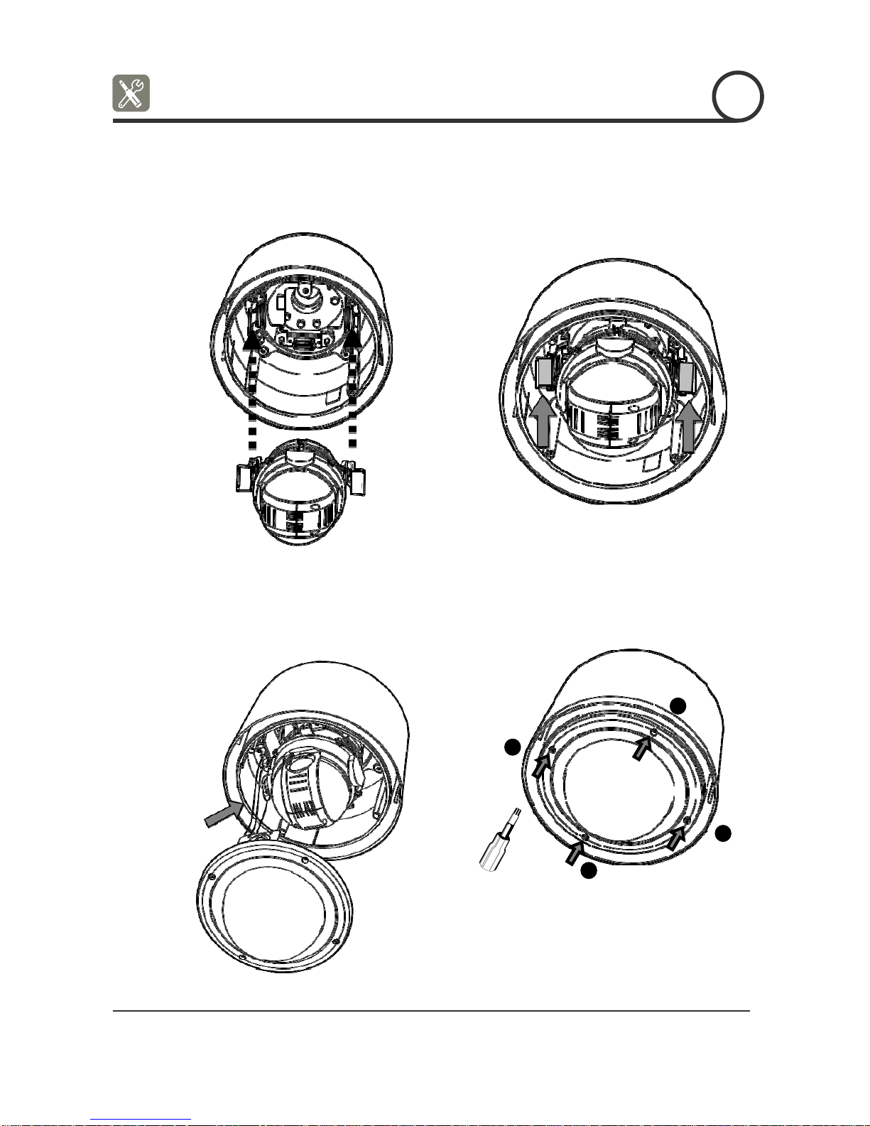
⑦ Plug the connector of cable from junction
box into properly. After checking the
orientation of one touch connector in the
upper housing, press the PTZ mechanism into
hook in the upper housing.
⑧ To lock the PTZ mechanism to the upper
housing, press the two black handles till it
sounds snap.
⑨ Close the dome cover. Care must be taken
to locate dome cover by matching the
“Arrow” mark.
⑩ Tighten four screws on the dome cover in
sequence as shown in the picture bellow.
4
1
2
3
a To maintain the best sealing, the torque of
each screw must be in the range between 0.5 ~
1.0 N·m (0.37 ~ 0.73 lbf·ft).
ANTI-VANDAL 30x, 36x, 37x SPEED DOM
15/46
 Loading...