

Eyemax HD4K-1.0(A01) User Manual

0
NETWORK VIDEO RECORDER
USER GUIDE
VER HD4K-1.0(A01)
Thank you for purchasing this HD IP Network Video Recorder.
Before using the IP Network Video Recorder, please ensure that you read and
understand the User Guide.
Please store the User Guide at an easily accessible location.
Before connecting and installing any third party IP cameras, monitors, alarms and
computers, please refer to the appropriate instruction manual for proper operation.
1
SAFETY PRECAUTIONS
CAUTION:
TO REDUCE THE RISK OF ELECTRIC SHOCK, DO NOT REMOVE COVER (OR BACK).
NO USER SERVICEABLE PARTS INSIDE. REFER SERVICING TO QUALIFIED
SERVICE PERSONNEL.
The lightning flash with arrowhead symbol, within an equilateral
triangle, is intended to alert the user to the presence of un insulated
“dangerous voltage” within the product’s enclosure that may be of
sufficient magnitude to constitute a risk of electric shock to persons.
The exclamation point within an equilateral triangle is intended to
alert the user to the presence of important operating and
maintenance (servicing) instructions in the literature accompanying
the appliance.
WARNING:
TO PREVENT FIRE OR ELECTRIC SHOCK HAZARD,
DO NOT EXPOSE THIS APPLIANCE TO RAIN OR MOISTURE.

2
Contents
Disclaimer .............................................................................................. 5
Warning .................................................................................................. 5
Caution .................................................................................................. 6
Preventing Malfunction......................................................................... 7
Regulatory ............................................................................................. 7
Package Contents ................................................................................. 9
I.CONTROLS ........................................................................................ 10
1. Front Panel .................................................................................................... 10
2. Rear Panel Connectors ................................................................................. 11
3. Remote Controller ........................................................................................ 13
4. Mouse Control .............................................................................................. 15
5. Virtual Keyboard for Mouse Control ........................................................... 15
III.QUICK START PAGE ....................................................................... 16
IV.LIVE VIEWING ................................................................................. 19
1. Display Overview .......................................................................................... 19
2. Multi-screen Display and Sequencing ........................................................ 21
2.1. Screen Display. ....................................................................................................... 21
2.2. Multi-screen Display and Switch Sequencing Display. ....................................... 21
3. Quick button for multi screen Display. ....................................................... 22
3.1. Quick multi split mode change .............................................................................. 22
3.2. Repositioning .......................................................................................................... 22
4. Zooming ........................................................................................................ 23
V. OPERATION ..................................................................................... 24
1. LOG IN/OUT. .................................................................................................. 24
2. NAVIGATION THE MENU .............................................................................. 25
VI. SETUP............................................................................................. 26
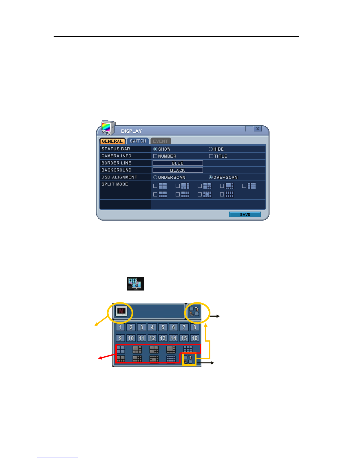
1. DISPLAY ........................................................................................................ 26
1.1. GENERAL ................................................................................................................ 26
1.2. SWITCH Setup (Monitor Configure) ...................................................................... 27
1.3. EVENT ...................................................................................................................... 28
2. CAMERA…………………………………………………………………… ……………………29
3. RECORD ........................................................................................................ 33
3.1. Record General ....................................................................................................... 33
3.2. Continues /Normal Recording ............................................................................... 34
3.4.1 Alarm Recording ..................................................................................................... 35

3
3.4.2 Motion Recording ................................................................................................. 36
3.4.3 Multi Event Recording . ................................................................................... 36
3.5 Continuous + Event (Motion/Alarm) Recording .................................................... 37
4. SCHEDULE .................................................................................................... 38
4.1. CHART Setup .......................................................................................................... 38
4.2. Holiday Setup .......................................................................................................... 40
5. DISK ............................................................................................................... 41
5.1. DISK Manager .......................................................................................................... 41
5.2. Recording DISK ....................................................................................................... 43
5.3. S.M.A.R.T STATUS .................................................................................................. 44
6. NETWORK ..................................................................................................... 45
6.1. LAN Port & IPCAM Port ............................................................................................ 45
6.2. GENERAL ................................................................................................................ 46
6.3. EMAIL ....................................................................................................................... 57
6.4. SMTP ........................................................................................................................ 58
6.5. DDNS (Dynamic DNS) ............................................................................................. 59
6.6 Router & Port Forwarding ....................................................................................... 61
7. DEVICE .......................................................................................................... 62
7.1. GENERAL ................................................................................................................ 63
I/O Terminal ..................................................................................................................... 64
7.3. PTZ EVENT .............................................................................................................. 67
8. SYSTEM ......................................................................................................... 68
8.1. GENERAL ................................................................................................................ 68
8.2. TIME .......................................................................................................................... 69
8.3. ACCOUNT ................................................................................................................ 70
8.4. UPDATE .................................................................................................................... 72
8.5. INFO .......................................................................................................................... 73
VII. PAN/TILT ZOOM CONTROL .......................................................... 74
1. P.T.Z. Menu .................................................................................................... 74
2. Preset & Tour ................................................................................................ 76
3. Custom Functions ........................................................................................ 77
4.Auto Pan / Auto Tilt / Power .......................................................................... 77
VIII.PLAYBACK /SEARCH ................................................................... 78
1. Playback ........................................................................................................ 78
2. Time Search .................................................................................................. 78
3. Go to Search ................................................................................................. 83
4. Log List Search ............................................................................................. 84

4
IX.BACKUP .......................................................................................... 85
1. Manual Back Up ............................................................................................ 85
2. Auto Back Up (FTP) ...................................................................................... 88
3. Log List Back Up .......................................................................................... 89
X.CLIENT .............................................................................................. 90
XI.SPECIFICATION .............................................................................. 91

5
Disclaimer
The information in this manual is believed to be accurate and reliable as of the date of
publication. The information contained herein is subject to change without notice. Revisions
or New editions to this publication may be issued to incorporate such change
We makes no warranties for damages resulting from corrupted or lost data due to a mistaken
operation or malfunction of the Network Video Recorder, the software, the hard drives,
personal computers, peripheral devices, or unapproved/unsupported devices.
Warning
Do not cover the ventilation opening or slots on the outer casing. To prevent the appliance
from overheating, provide at least two inches of air space around the vent and the slots.
Do not drop metallic parts through slots. This could permanently damage the Digital Video
Recorder. Immediately turn the NVR’s power off or unplug the power cord from the power
outlet. Contact a qualified service personnel authorized by your equipment distributor
Do not attempt to disassemble or alter any part of the equipment that is not expressly
described in this guide. Disassembly or alteration may result in high voltage electrical shock.
Qualified service personnel authorized by your equipment distributor should conduct internal
inspections, alterations and repairs.
Stop operating the equipment immediately if it emits smoke or noxious fumes. Failure to do
so may result in fire or electrical shock. Immediately turn the NVR’s power off, remove the
power cable from the power outlet. Confirm that smoke and fume emissions have ceased.
Please consult your NVR distributor.
Stop operating the equipment if a heavy object is dropped or the casing is damaged. Do not
strike or shake. Failure to do so may result in fire or electrical shock. Immediately turn the
NVR’s power off or unplug the power cord from the power outlet. Please consult your NVR
distributor.
Do not allow the equipment come into contact with, or become immersed in, water or other
liquids. Do not allow liquids to OK the interior. The NVR has not been waterproofed. If
the exterior comes into contact with liquids or salt air, wipe it dry with a soft, absorbent cloth.
In the event that the water or other foreign substances OK the interior, immediately turn the
NVR’s Power off or unplug the power cord from the power outlet. Continued use of the
equipment may result in fire or electrical shock. Please consult your NVR distributor.
Do not use substances containing alcohol, benzene, thinners or other flammable substances
to clean or maintain the equipment. The use of these substances may lead to fire. Use a

6
dry cloth on a regular periodic basis and wipe away the dust and dirt that collects on the
device. In dusty, humid or greasy environments, the dust that collects around the ventilation
or the slots on the outer casing over long periods of time may become saturated with
humidity and short-circuit, leading to fire.
Do not cut, damage, alter or place heavy items on the power cord. Any of these actions
may cause an electrical short circuit, which may lead to fire or electrical shock.
Do not handle the device or power cord if your hands are wet. Handling it with wet hands
may lead to electrical shock. When unplugging the cord, ensure that you hold the solid
portion of the plug. Pulling on the flexible portion of the cord may damage or expose the
wire and insulation, creating the potential for fires or electrical shocks.
Use only the recommended power accessories. Use of power sources not expressly
recommended for this equipment may lead to overheating, distortion of the equipment, fire,
electrical shock or other hazards.
Do not place the batteries near a heat source or expose them to direct flame or heat.
Neither should you immerse them in water. Such exposure may damage the batteries and
lead to the leakage of corrosive liquids, fire, electrical shock, explosion or serious injury.
Do not attempt to disassemble, alter or apply heat to the batteries. There is serious risk of
injury due to an explosion. Immediately flush with water any area of the body, including the
eyes and mouth, or clothing that comes into contact with the inner contents of the battery. If
the eyes or mouth contact these substances, immediately flush with water and seek medical
assistance from a medical professional.
Avoid dropping or subjecting the batteries to severe impacts that could damage the casings.
It could lead to leakage and injury.
Do not short-circuit the battery terminals with metallic objects, such as key holders. It could
lead to overheating, burns and other injuries.
The supplied power supply and power cord are designed for exclusive use with the Digital
Video Recorder. Do not use it with other products or batteries. There is a risk of fire and
other hazards.
Caution
Do not operate the appliance beyond its specified temperature, humidity or power source
ratings. Do not use the appliance in an extreme environment where there is high
temperature or high humidity. Use the device at temperatures within +0°C - +40°C (32°F 104°F) and humidity below 90 %. The normal operating power source for this device is 100V240V AC 50/60Hz.

7
Preventing Malfunction
Avoid Strong Magnetic Fields. Never place the NVR in close Proximity to electric motors or
other equipment generating strong electromagnetic fields. Exposures to strong magnetic
fields may cause malfunctions or corrupt image data.
Avoid Condensation Related Problems. Moving the equipment rapidly between hot and cold
temperatures may cause condensation (water droplets) to form on its external and internal
surfaces. You can avoid this by placing the equipment in an airtight, resalable plastic bag and
letting it adjust to temperature changes slowly before removing it from the bag.
If Condensation forms inside the Digital Video Recorder. Stop using the equipment
immediately if you detect condensation. Continued use may damage the equipment. Remove
the power cord from the power outlet and wait until the moisture evaporates completely
before resuming use.
FCC Compliance : This equipment has been tested and found to comply with the limits for a
Class A digital device, pursuant to part 15 of the FCC Rules. These limits are designed to provide
reasonable protection against harmful interference when the equipment is operated in a commercial
environment. This equipment generates, uses, and can radiate radio frequency energy and, if no
installed and used in accordance with the instruction manual, may cause harmful interference to radio
communications. Operation of this equipment in a residential area is likely to cause harmful
interference in which case the user will be required to correct the interference at his own expense.
Description on Laser Specification
The optical disc drive such as DVD Super Multi (Double Layer) Drive 22X that is used in this computer
is equipped with laser. The classification label with the following sentence is affixed to the surface of
the drive.
CLASS 1 LASER PRODUCT TO IEC60825-1 LASER KLASSE 1 The drive with the above label is
certified by the manufacturer that the drive complies with the requirement for laser product on the date
of manufacturing pursuant to article 21 of Code of Federal Regulations by the United States of
America, Department of Health & Human Services, Food and Drug Administration. In other countries,
the drive is certified to comply with the requirement pursuant to IEC 60825-1 and EN 60825-1 on class
1 laser product. This computer is equipped with the optical disc drive in the following list according to
the model.
EU Conformity Statement:
Regulatory

8
2002/96/EC (WEEE Directive) : Products marked with this symbol cannot be disposed of
as unsorted municipal waste in the European Union. For proper recycling, return this
product to your local supplier upon the purchase of equivalent new equipment, or dispose of
it at designated collection points. For more information, see: www.recyclethis.info.
2006/66/EC (Battery Directive) : Products marked with this symbol cannot be disposed of
as unsorted municipal waste in the European Union. For proper recycling, return this
product to your local supplier upon the purchase of equivalent new equipment, or dispose of
it at designated collection points. For more information, see: www.recyclethis.info.
NOTE: THE MANUFACTURER IS NOT RESPONSIBLE FOR ANY RADIO OR TV INTERFERENCE
CAUSED BY UNAUTHORIZED MODIFICATIONS TO THIS EQUIPMENT. SUCH MODIFICATIONS
COULD VOID THE USER'S AUTHORITY TO OPERATE THE EQUIPMENT.
CAUTION
- Risk of Explosion if Battery is replaced by an Incorrect Type. Dispose of Used Batteries
according to the Instructions.
- The socket-outlet shall be installed near the equipment and shall be easily accessible

9
Package Contents
Please check the package and contents for visible damage. If any components are damaged or
missing, do not attempt to use the unit, contact the supplier immediately. If the unit must be
returned, it must be shipped in the original packing box.
CONTENTS
QUANTITY
REMARK
NVR SET
1 UNIT
MOUSE
1
REMOTE CONTROL
1
BATTERY (AAA size)
2
ADAPTER (12V/5A)
1
For NVR SET
ADAPTER (48V/1A or 48V/2A)
1
For PoE Power
POWER CORD
2
HDD BRACKET
4
To install HDDs
HDD CABLE
2
CLIENT SOFTWARE CD
1
Manual included
10
I.CONTROLS
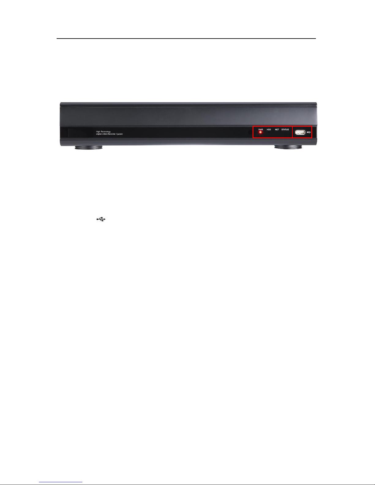
1. Front Panel
1) Mode Indicator: 4 LEDs display the status of the Network Video Recorder.
- PWR : Power ON / OFF status
- HDD : Blinking if Recording in the HDD or Playback
- NET : Network connection
- STATUS : Responding with Buzzer
2) USB : USB compliant port allows use of memory stick to backup video files or S/W
upgrade and Mouse.

11
2. Rear Panel Connectors
4ch PoE
8ch PoE
W/O PoE
1 2 3 4 5 6 7 8 ..9 ..10 1112 13 14
1 2 3 4 5 6 7 8 ..9 ..10 1112 13 14
15 3 4 5 6 7 8 ..9 ..10 1112 13 14

12
1) POWER(48V) : DC power Jack (PoE model only)
2) IP PoE Camera input : RJ45 input connectors (PoE model only)
3) AUDIO Output connector: RCA port(mono) for audio output.
4) AUDIO Input connector: RCA port(mono) for audio input.
5) HDMI out connector: Used as the main video output.
6) VGA out connector: Used as the main video output
7) RS-232C [D-SUB 9PIN]: For connecting to Debugging.
8) e-SATA connector: For connecting e-SATA compatible devices.
9) USB 2.0 connector: For connecting USB compatible devices.
10) LAN Port: For connecting to remote PC via Ethernet network.10/100/1000 BASE-T
11) RS485 : To connect and control PTZ IP Cameras
12) Alarm Input : To connect Alarm input device
13) Alarm Output : To connect the Alarm output device
14) POWER(12V) : DC power Jack for NVR unit
15) IP Camera Port : IP Camera input (None PoE model only)

13
3. Remote Controller
NVR ID: Set the proper NVR System ID through which to operate. Press the ID button, and
then press the number button within two seconds to select the system ID of the NVR. If you
set the System ID to Zero, you can control multiple NVRs at the same time.
① NVR ID
② Power
③ System Configuration Buttons
④ Navigation / OK
⑤ Playback Controls
⑥ Channel Buttons

14
- Letters in Device
Allows you to create a unique name for each camera and put figures in set up menu.
User can use the virtual keyboard or press the appropriate numeric button on the IR
Remote or the front panel.
<on Front Panel >
<On IR Remote Controller >
No
1st
2nd
3rd
4th
5th
6th
7th
8th 1 a b c 1 A B C 1 2 d e f 2 D E F 2 3 g h i 3 G H I 3 4 j k l 4 J K L 4 5 m n o 5 M N O 5 6 p q r 6 P Q R 6 7 s t u 7 S T U 7 8 v w x 8 V W X 8 9 y z @ 9 Y Z @ 9 10/0 . - _ 0 . - _ 0
No
1st
2nd
3rd
4th
5th
6th 1 a b 1 A B
1
2 c d 2 C D 2
3 e f 3 E F 3 4 g h 4 G H 4 5 i j 5 I J 5 6 k l 6 K L 6 7 m n 7 M N 7 8 o p 8 O P
8 9 q r 9 Q R
9
10/0
s t 0 S T
10
11
u v U
V
12
w X W
X
13
y z Y
Z
14
. @ .
@
15
- _ -
_
16
space
15
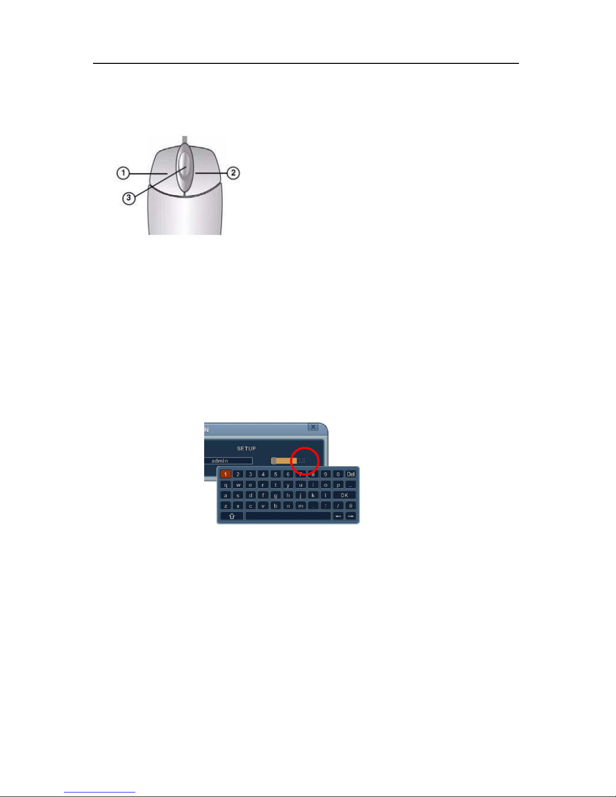
4. Mouse Control
This IP NVR can be controlled by the mouse. Connect
the mouse to the USB port before use.
1) Left-Button -Double Click on any channel to enlarge
to full screen while in a split-screen display mode and
double click again to return.
Select the menu option while navigating through various
menu options.
2) Right Button- Right click anywhere on the screen to
open main menu. Double click to return.
3) Scroll Wheel: move the scroll wheel up or down to increase/decrease the value of the
selected menu option.
5. Virtual Keyboard for Mouse Control
This system provides a virtual on-screen keyboard to perform the control by mouse.
Connect a mouse via USB port before use.
<Virtual Keyboard>
16
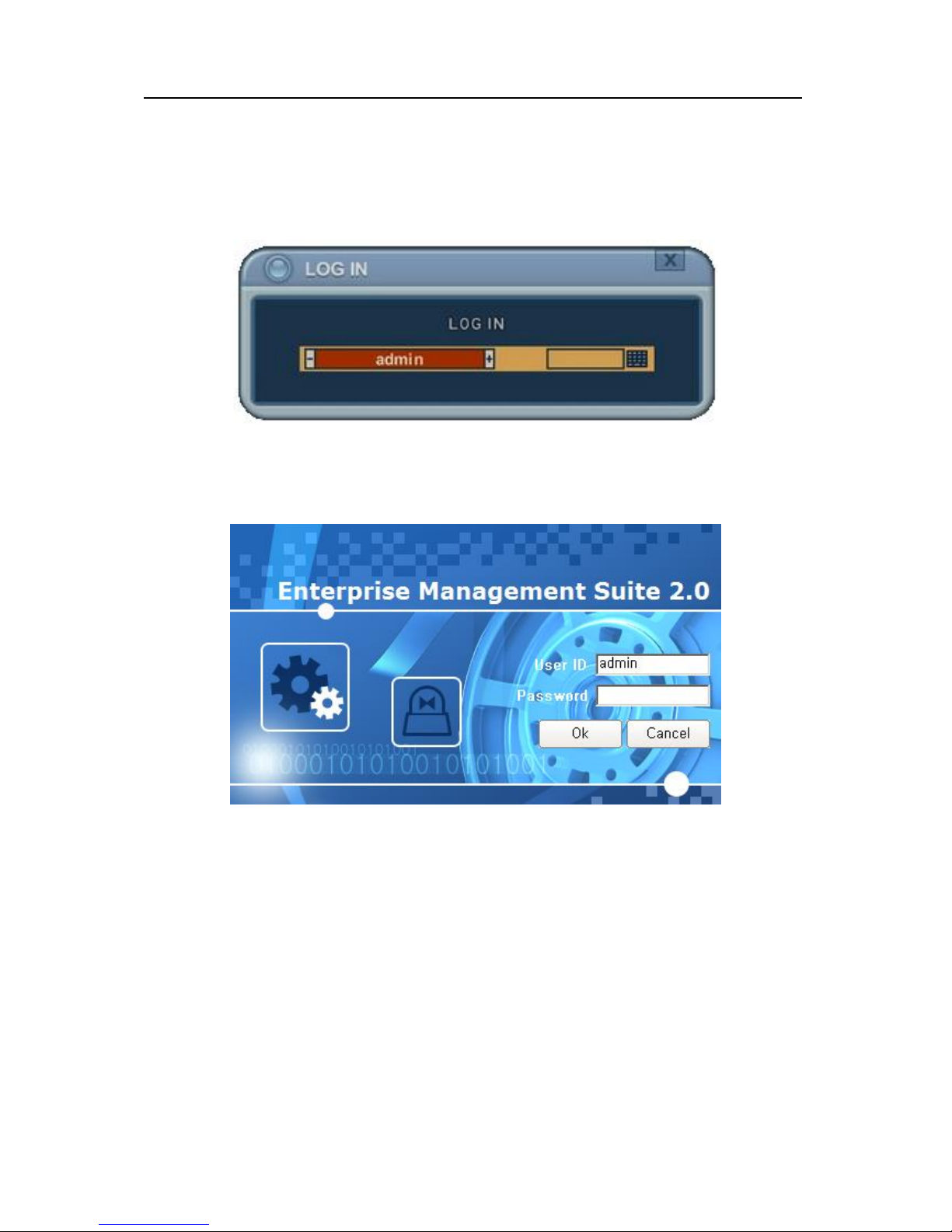
III.QUICK START PAGE
"admin "and the default password is “000000”
The Default User ID “admin” and password to run the EMS 2.0 software is “0”
17
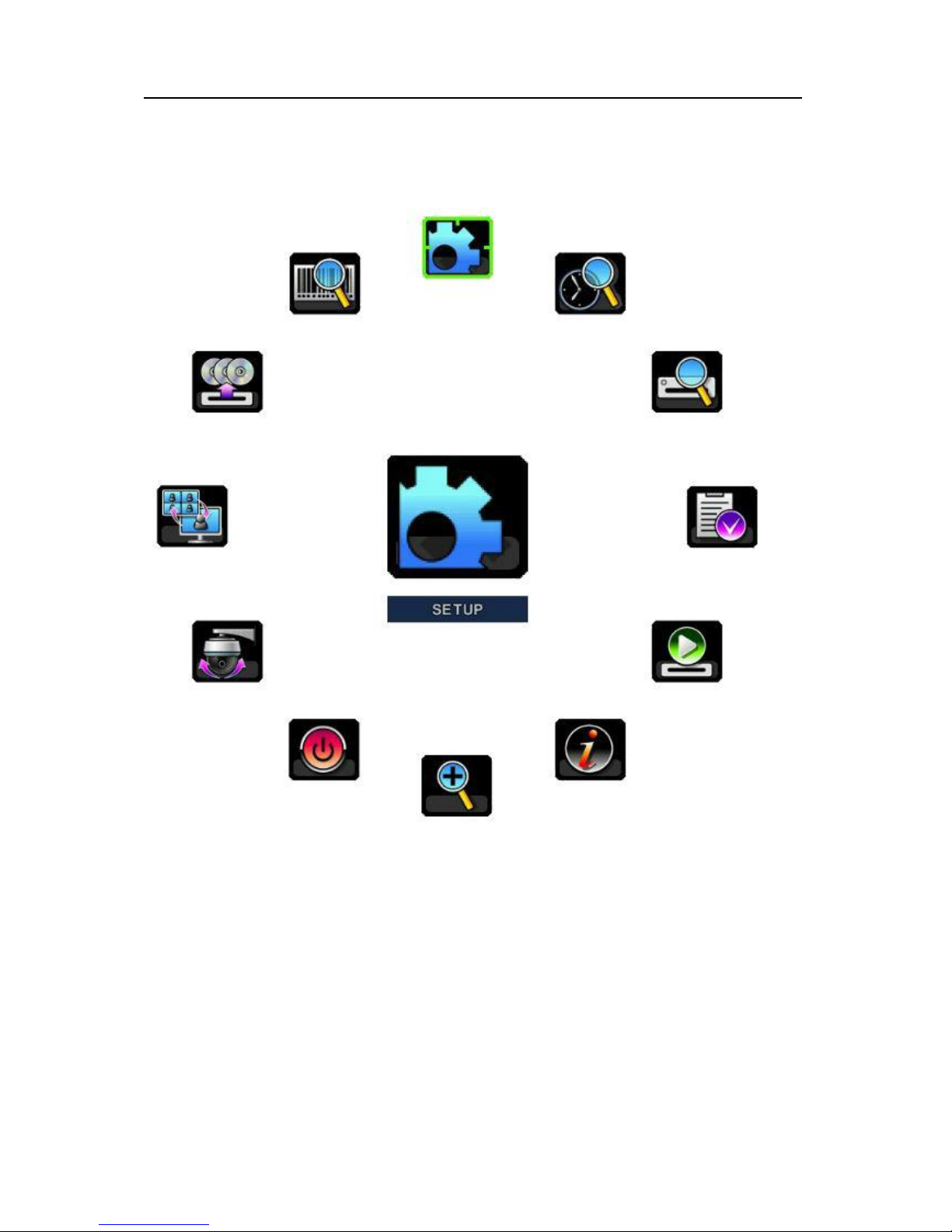
Main Menu
Set up
Time Search
External Search
Power
Zoom
System info
Playback
Log
PTZ
Display
Backup
POS Search
18
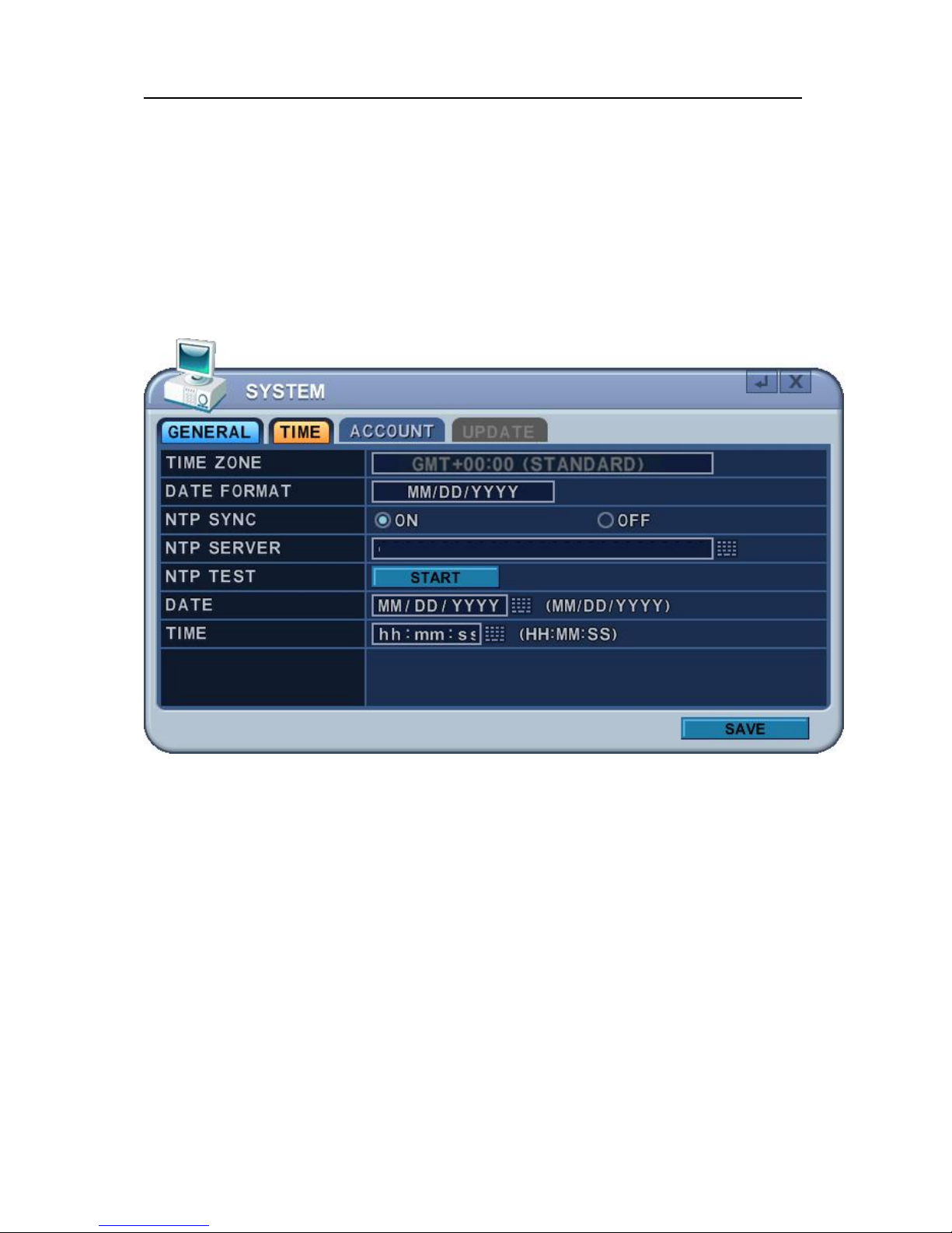
Time & Date Setting
When the NVR is powered on for the very first time, the time and date are set as default to
January 1, 2009 Thursday 01:00:00. Before any other operation of the Network Video
Recorder, it is important to setup the time and the date. Please refer for setting the time and
the date on the NVR.
19
IV.LIVE VIEWING
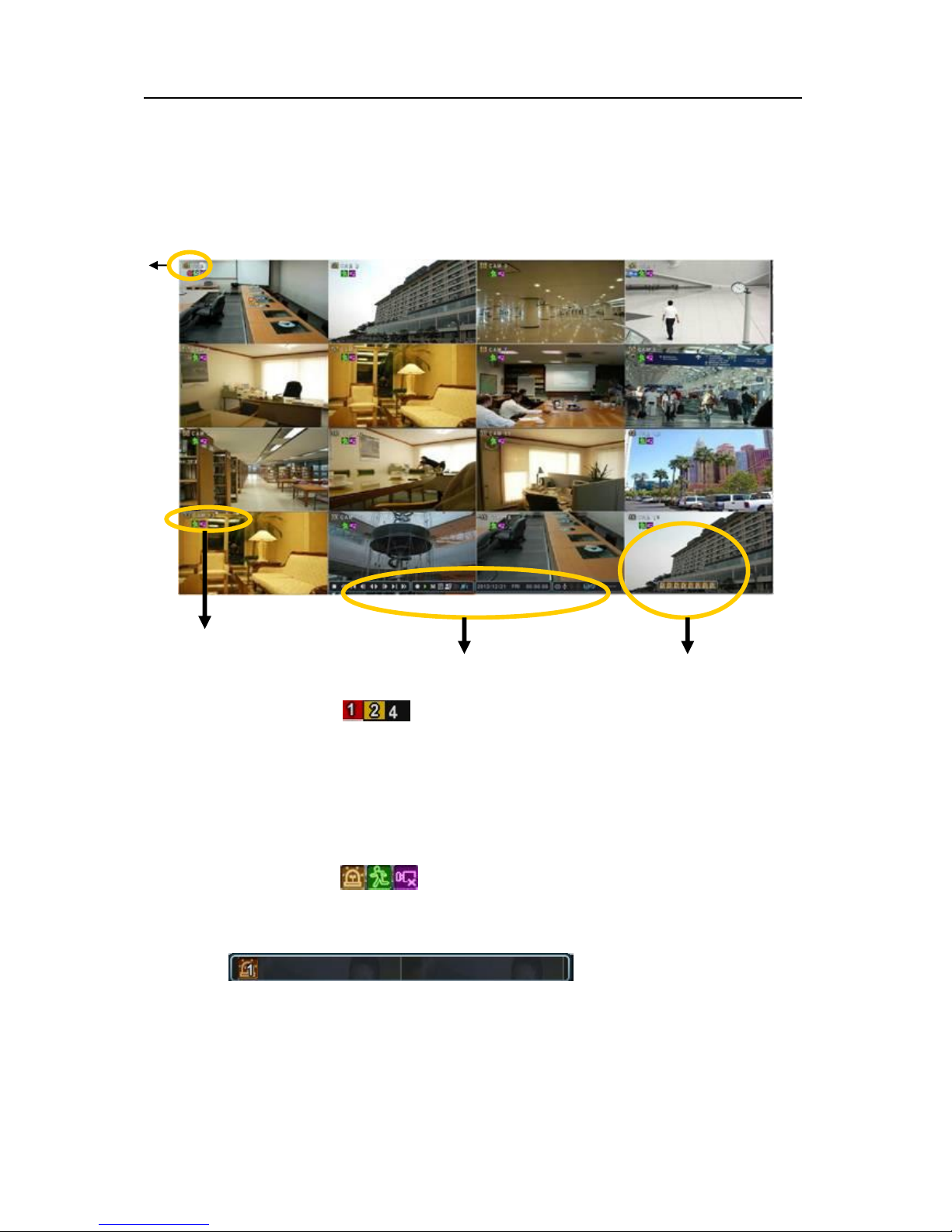
1. Display Overview
1. Recording Mode
Background color of Number will be different based on the recording status.
1) Red - Event (Motion/Alarm) Recording
2) Yellow - Continuous Recording
3) Black - No Recording.
2. Event Indicator
(1) Indicate Alarm In terminal is triggered by an alarm sensor.
To appear Alarm window, press [UP] button. This button toggles between Shows
or Hide the Alarm Window.
(2) Indicate Motion detected. To disappear, press [ESC] button.
(3) Indicate Video Loss during Recording. To disappear, press [ESC] button.
(1) (2) (3)
Camera
④
②
20
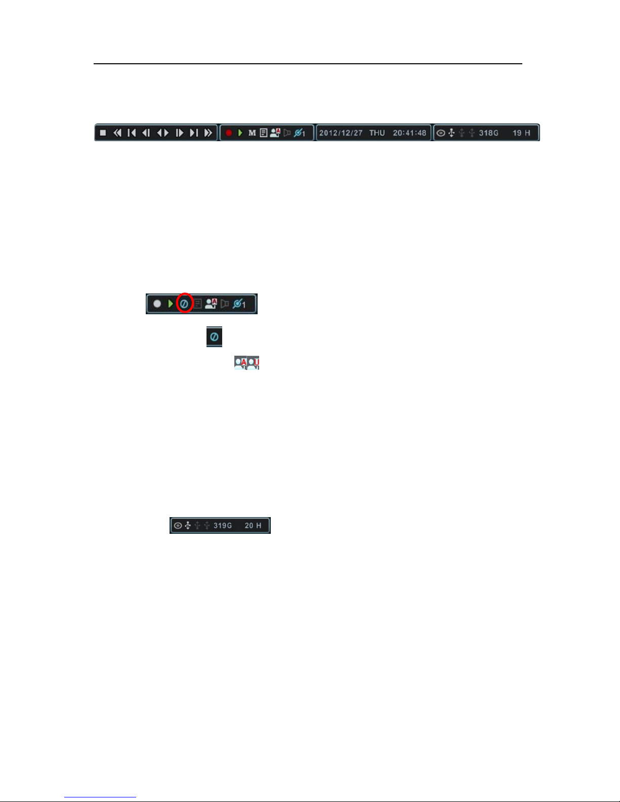
3. Status Bar
(1) This ICON will be shown only on play back mode.
(2) Indicate Recording Status. Red is Recording. Click this ICON to toggle
Record Start and Stop.
(3) Indicate Playback Status. Green is Playback. Click this ICON to toggle
Playback Start and Stop.
(4) Indicate Menu. Click this ICON to popup the menu.
(5) Indicate LOG. Click this ICON to popup log history.
=> After click Menu and LOG, the status bar is changed like below picture.
Please click ICON to clear Menu and LOG.
(6) Indicate Login( ) or Locking status. Click this ICON to toggle Log in and
out.
(7) Indicate Audio Data is stored the selected time during playback and turn to
blue color.
(8) It shows Number of Client, which is connected to Network.(MAX:10)
(9) Displays Month, Year, Time and Date. Change the order on System>Time.
(10) Indicate an USB Device is connected on Front panel and Rear panel.
It’s changed to blue color while it’s doing backup. Click this ICON to toggle Back
up Start and Stop.
(11) : Show you the remaining recording time of the NVR. If
remaining HDD capacity is less than 5GB, this blue “Recycling” icon will be
shown up.(DVD icon would not be shown some models if DVD-RW is not
supported)
(1) (2) (3) (4) (5)(6)(7) (8) (9) (10) (11)
21
2. Multi-screen Display and Sequencing
2.1. Screen Display.
Select any camera for Full screen display by pressing the Number button of the
desired camera. for 12ch, press 1 then 2.
2.2. Multi-screen Display and Switch Sequencing Display.
1) Press [DISPLAY] buttons to activate the multiscreen display. It is changed the
order as shown below among your choice of SPLIT MODE.
2) To start Auto Sequence, press [DISPLAY] buttons for 2 seconds to begin full
screen sequencing.
Click this ICON by Mouse and spot out button on the remote control,
you will see following virtual controller
Main Monitor
Spot Monitor
3) The Auto sequence mode and dwell times are programmable in Switch set up.
For detailed information about configuring those, see “Switch Setup”. If the
sequence mode is not activated, it moves to Quad mode instead of Sequencing.
4) The Split mode is programmable in General set up.
Auto Sequence Status
Auto Sequence
SPLIT MODE
22
3. Quick button for multi screen Display.
3.1. Quick multi split mode change
- Press F1 button on the remote controller + <Number>
For example, press F1 button then number 8.
4
8
3
7
2
6
10
1
5
9
11 12
13 14 15 16
2
3
4
8765
1
The eight channel view mode will be displayed.
<Note> 6,4,8,10,13 split mode must be checked on <Spit mode> to use this
function.
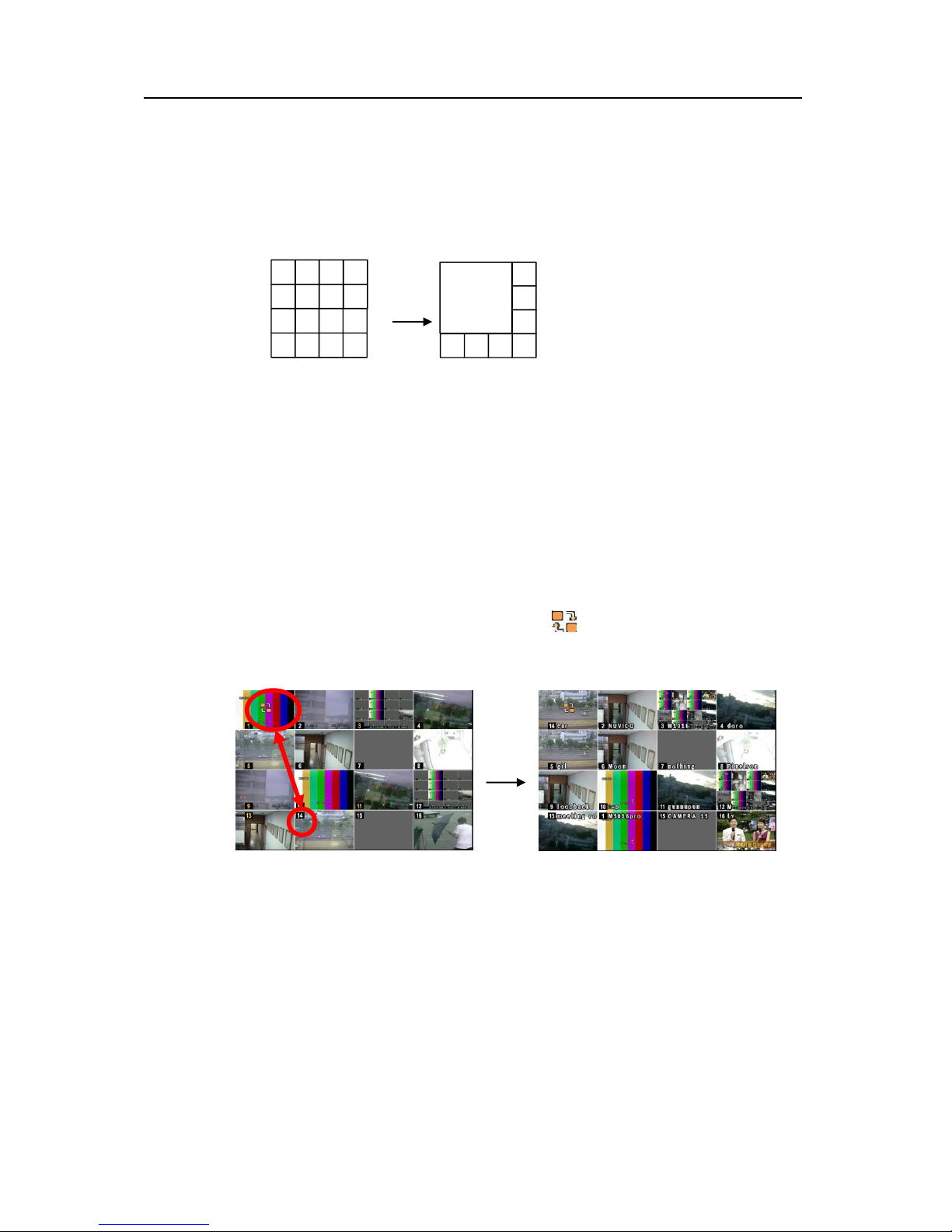
3.2. Repositioning
It is possible to reposition the camera from the bigger window with the one from a
smaller one. It is used on 6,7,8,9,10, 13,16 split mode
① Press F2 button on the remote controller. Mark will be displayed.
② Press Numeric button you wish to switching display.
③ Press [MENU] button to exit here with saving changes.
Press [Cancel] to exit without change.
Press [DISPLAY] button to rearrange.
23
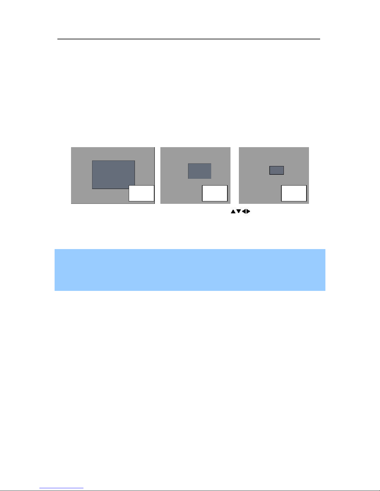
4. Zooming
During live view mode, it is possible to zoom into a section of the screen to get a close-up
view of the screen.
1. To activate the digital zoom, select the full screen display of the camera you wish to
zoom.
2. Then press the [ZOOM] button on IR Remote controller. Zoom area box pops up, as
shown below.
3. Move the box to the desired position using Direction [ ] buttons.
4. Press [+] button to enlarge the image. Press [ - ] button to zoom out the image.
5. Press [ESC] button to return normal mode.
<Note>
If the Zoom button is pressed while in a multi-screen display, zoom operation is not
activated.
x 2
x 4
x 8

24
V. OPERATION
1. LOG IN/OUT.
You must log on to the NVR with valid password to operate the NVR. By default, it comes
with one login account; ADMIN and the default password is “000000”.
<Note > If you are logging on for the first time, the system does not prompt you to change
the default password. Therefore, it’s strongly recommended to change the “PASSWORD”
when you install the NVR. Refer to [System Setup].
1. Login
1) On the front panel or remote control, press the power button.
2) When the NVR is powered on, it will start to scan NVR status.
3) Live Viewing screen will appear after initialization about 50sec. It can be delayed
when you have defect HDD, it will try to fix for logical problem but it will show you
warning message for physical problem.
4) On the remote control, press Login. Using the mouse, click the login icon, login
dialog box pops up.
5) Login Icon will be changed on status bar.
2. Logout
On the remote control, press LOGIN. Using the mouse, Press Login icon again,
indication you are logged off.

25
2. NAVIGATION THE MENU
1. Log on the NVR at admin level or user with configure level.
* User with configure feature is limited to access [DISK and System Menu].
2. On the front panel or remote control, press [MENU]. Using the mouse, Right click
wherever on monitor, Menu will be appeared.
3. Use Direction buttons [ ,+/-] to select the desired menu. Using the mouse, click
the menu. Items selected .
4. Press [OK] button to select the menu and display Sub-Menu. Using the mouse,
double click.
5. Use Left/ Right buttons [ ] to select on TAP menu. Selected items changed into
[Orange] color.
* It is automatically saved changes when you move between TAP menus.
6. The menus are displayed with options on the left-hand column and settings in the
right hand column. A cursor (highlighted menu) can be moved using the Direction
buttons [ ] .
7. Press [-, +] or wheel button to change the value or select options. By mouse, using
Wheel.
8. Press [SAVE] button to exit a menu with saving changes.
Selected Not selected Inactivated
 Loading...