

Eye Lighting Aphos Installation Instructions Manual
Installation Instructions
EQS3423 REV: D
WARNING
Risk of electrical shock. Disconnect power before
servicing or installing Luminaire.
Risqué de choc électrique. Couper l’alimentation avant
l’entretien.
WARNING
Risk of injury or damage. Luminaire will fall if not
installed properly. Read and follow installation
instructions before beginning.
Risqué de blessure. Une installation inappropriée peut causer
la chute de l'ensemble luminaire. Lisez les informations ci-
dessous avec attention avant d’utiliser ce produit.
CAUTION
Risk of injury. Wear safety glasses, gloves, and any
required PPE during installation and servicing.
Risqué de blessure. Portez des lunettes de sécurité et des
gants lors de l’installation.
Aphos
READ AND FOLLOW THE INSTALLATION
INSTRUCTIONS ON SHEET 2.
Tools Required:
Installation is completed using ordinary tools
including:
Driver or wrench with SAE 7/16 inch hex
socket
Torque wrench capable of 20 ft-lbs
(20.0 N-m)
Wire strippers suitable for 18 AWG and
gauge of supply wire.
#2 Phillips screwdriver.
IMPORTANT SAFETY INSTRUCTIONS:
This equipment is intended to be installed by qualified personnel. The installation must be made in accordance with the current edition of the
National electric Code, and all applicable state and local building codes. The final installation must be approved by the appropriate, qualified,
electrical/building inspector(s). Improper installation may result in a risk of fire or electrical shock hazard. The instructions provided herein are
made available for reference when installing the Aphos™ CM Luminaire and do not claim to represent all possible installation variations. If any
portion of these installation instructions are unclear, then do not proceed with the installation and contact an EYE Lighting representative.
Cet équipement est conçu pour être installé par un personnel qualifié. L’installation doit être conforme au “National Electric Code” (É-U) et (ou) à
tout autre code du bâtiment de votre État, province ou municipalité. L’installation definitive doit être approuvée par un inspecteur en bâtiment et
(ou) un électricien qualifié tel qu’approprié. Une installation inappropriée peut résulter en un risqué de feu ou de choc électrique. Les instructions
ci-jointes sont fournies à titre de référence pour l’installation de l’ensemble luminaire. Ne procédez pas à l’installation si une partie de ces
instructions n’est pas claire et contactez plutôt un représentant d’EYE Lighting.
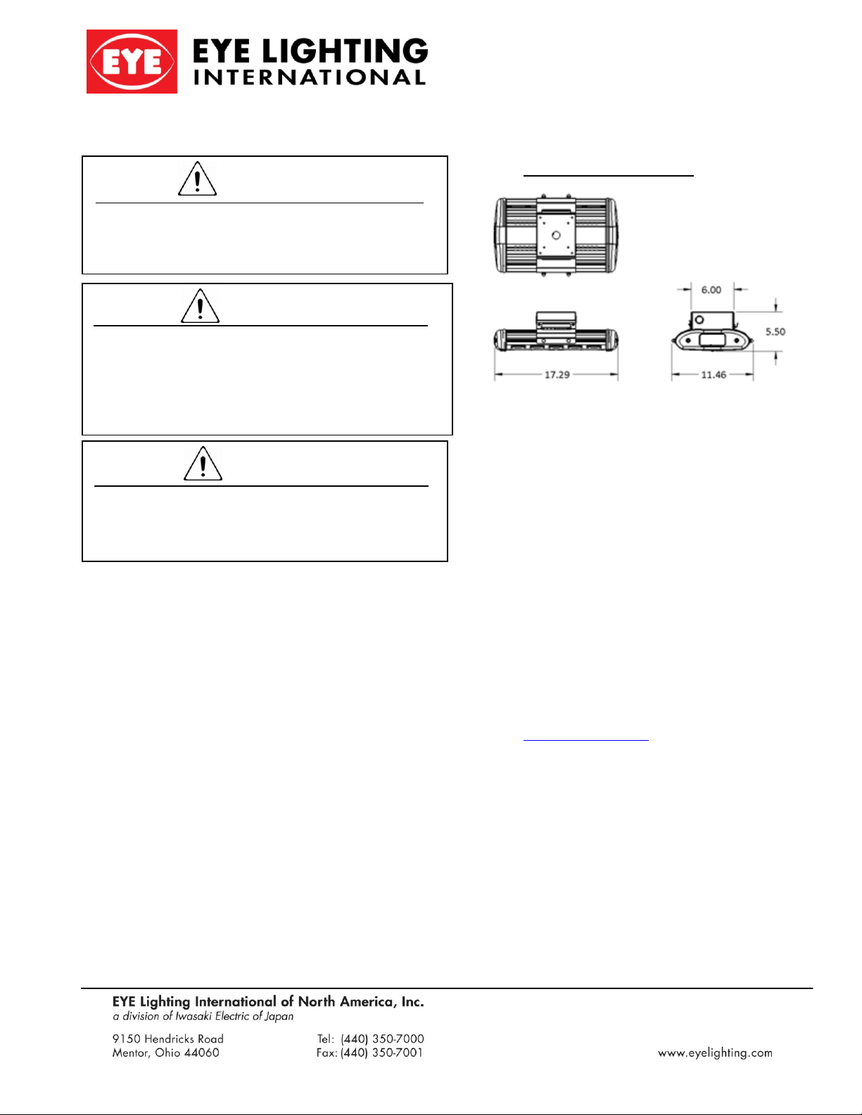
General Dimensions
Specifications:
Distribution:
IES Type II
IES Type III
IES Type V
Lumen Levels:
L3*
L7*
L10*
Weight: ~15 lbs (~6.8 kg)
IP Rating: Optical IP65, Driver IP66
Luminaire UL Wet Location Listed-E1 only.
UL Damp Location Listed-E2.
EPA: 0.32 ft2
Rated Voltage / Frequency: 120 to 277 VAC / 50
to 60 Hz
Rated Voltage / Frequency: 347/480 VAC / 50 to
60 Hz requires step-down autotransformer
Reference Photometric Data Sheet for lumen
output. Photometric Sheets can be found on
www.eyelighting.com
™
CM Luminaires
Installation Instructions
EQS3423 REV: D
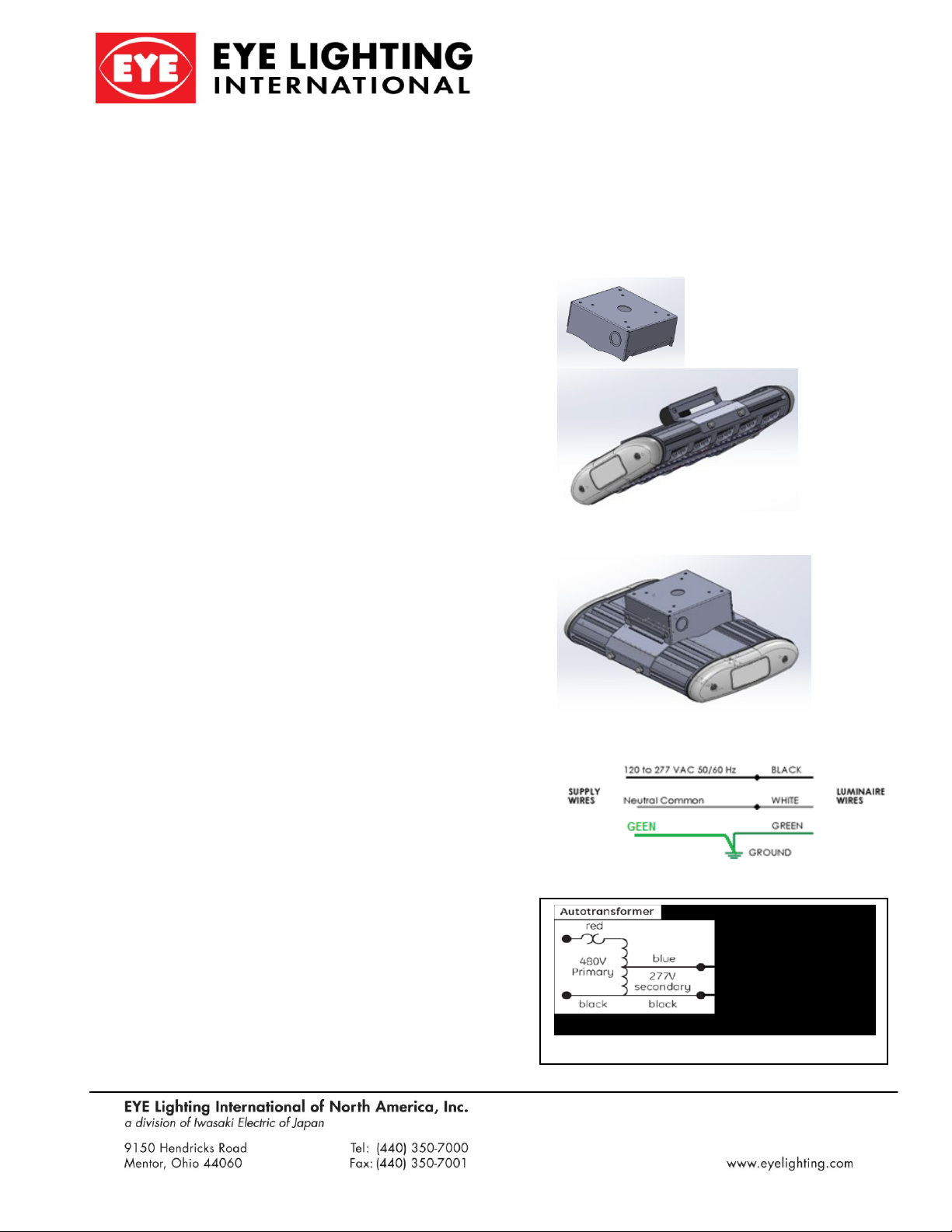
347-480V wiring
Aphos
™
CM Luminaires
INSTALLATION INSTRUCTIONS:
Read the instructions completely before starting
installation.
Installation shall be done in compliance with the
National Electric and Building Codes, as well as with
State and Local Code requirements in effect at the
time of installation. The local inspector has final
jurisdiction on any installation.
Ensure that supply power is off
Luminaire installation and service shall be executed
by qualified personnel only.
Unpack the luminaire and inspect for damage in
shipment. If it is damaged in any way, do not install.
Locate the manufacturer’s labels. Note all
specifications and warnings on the labels. Enter serial
number and installation date in area provided. Retain
this information and Instructions for future reference.
Ensure that junction box is appropriately sized and
sufficient to mount and support this luminaire. Refer
to Specifications given above for weight and
approximate dimensions.
Locate the power supply leads and route through the
center hole of the J Box Bracket. Attach the J Box
Bracket to the junction box, in a manner sufficient for
permanent mounting, pursuant to all local, state and
national codes. The provided holes in the J Box
Bracket will accept (4) 8-32 or M4-0.7 screws.
Place the luminaire onto J Box Bracket by inserting
the square flange side of the bracket through the slot
opening in the luminaire bracket which has no holes
next to the slot opening. Allow the luminaire to hang
in this position while electrical connections are made.
If the luminaire is equipped with E1 wiring (Wet
Location) connect the black lead to line/Phase 1, the
white lead to white/Phase 2, and the green lead to
ground. (See Figure 4 on sheet 3). If the luminaire is
equipped with E2 (Damp-Dry location) make
electrical connections to Terminal Block, matching
wire connections as described above.
Complete the installation by swinging the luminaire
up until the luminaire bracket meets and snaps
securely onto J Box Bracket. Insert screws (provided)
to secure luminaire bracket to J Box Bracket.
Make the electrical connections (Figure 2) if supply
voltage is 120 to 277 VAC or (Figure 3) if supply
voltage is 347 / 480VAC and using 480V to 277V
Step-Down Remote Mounted Autotransformer.
J Box Bracket
Figure 2
Luminaire Serial #:_____________
Date of
Installation:_____________Location:_____________
Luminaire Bracket
Assembled Luminaire
 Loading...