

Page 1
Page 1
eyeheight
Unit 34 Park House Watford Business Park Greenhill Crescent Watford Herts GB WD18 8PH
Reg. No. 2855535 Telephone: +44 (0) 1923 256 000 Fax: +44 (0) 1923 256 100 email: [email protected]
www.eyeheight.com
GeNETics
Product
Information
User Guide For:
BM-2
(PM-2E/PM-4)
Audio monitor
Revision1-25 February 2002
eyeheight
Page 2
Page 2
eyeheight
Unit 34 Park House Watford Business Park Greenhill Crescent Watford Herts GB WD18 8PH
Reg. No. 2855535 Telephone: +44 (0) 1923 256 000 Fax: +44 (0) 1923 256 100 email: [email protected]
The PM-2E/PM-4 Features and Overview ....................................................... 3
Applications for the PM-2E/PM-4 ..................................................................... 4
Associated Equipment for the PM-2E/PM-4 ..................................................... 4
Installation of the PM-2E/PM-4 Product ........................................................... 7
Installing the PM-2E/PM-4 into a Flexibox ....................................................... 7
CHP-100 SDI-TC-GPI Card ............................................................................. 8
Jumper Links on the Timecode and GPI I/O card ........................................... 8
Rear 25W D-Type connection (AUX) ............................................................... 8
Manual Control of the PM-2E/PM-4 ............................................................... 10
Operational Menus for the PM-2E/PM-4 ........................................................ 10
Technical Specification for the PM-2E/PM-4 .................................................. 13
Jumpering the I-BUS (CAN-BUS) Termination .............................................. 13
Figure 1 PM-2E/PM-4 Module. ........................................................................ 4
Figure 2 A typical PM-2E/PM-4 displays. ......................................................... 4
Figure 3 Flexibox with Flexipanel fitted ............................................................ 5
Figure 4 Minibox, Front and Rear. ................................................................... 6
Figure 5 Location of I-bus termination link ..................................................... 13
Table Of Contents
Table Of Figures
Page 3

Page 3
eyeheight
Unit 34 Park House Watford Business Park Greenhill Crescent Watford Herts GB WD18 8PH
Reg. No. 2855535 Telephone: +44 (0) 1923 256 000 Fax: +44 (0) 1923 256 100 email: [email protected]
This manual describes the function of the PM-2E/PM-4. This unit monitors the
embedded audio encoded within a SDI data stream. It also flags suitable
alarms and displays the information onto a screen overlaid onto a video
screen.
The PM-2E is a unit that will monitor the audio embedded in a SDI data
stream and the PM-4 monitors the AES. They check that both audio signals
are present and that they are not silent, alerting the operator when an error
occurs. The main features are as follows:-
The PM-2E monitors embedded audio channels 1 and 2, the PM-4
monitors AES 1 channels 1 and 2.
The user can define a 6 digit channel Ident, definable in foreground
colour, background colour, flashing or normal mode.
All the error messages can be user defined, in foreground colour,
background colour, flashing or normal mode and whether that condition
triggers an alarm.
The main “alert” alarms can be “accepted” by the operator setting a
second “indication” alarm, which is cleared when the problem is
completely resolved.
The module broadcasts information compatible with the MD-2 Master
Display module, enabling collation of any unit’s displays and allowing
for remote supervision.
The length of time required to trigger an alarm can be set by the
operator.
System Overview
1
Section 1
The PM-2E/PM-4 Product
Page 4
Page 4
eyeheight
Unit 34 Park House Watford Business Park Greenhill Crescent Watford Herts GB WD18 8PH
Reg. No. 2855535 Telephone: +44 (0) 1923 256 000 Fax: +44 (0) 1923 256 100 email: [email protected]
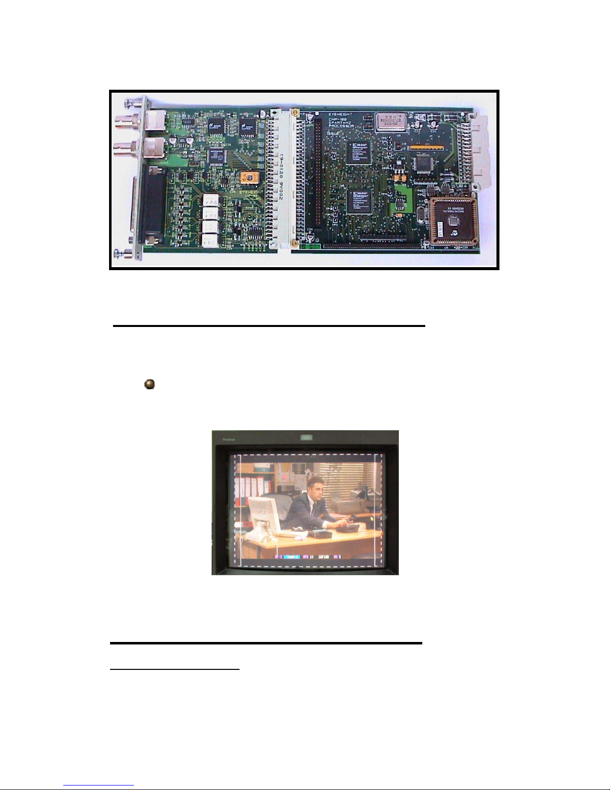
Figure 1 PM-2E/PM-4 Module.
Applications for the PM-2E/PM-4 include the following:-
Automatic monitoring of a SDI channel and flagging suitable alarms
to alert the operator in user defined situations.
Figure 2 A typical PM-2E/PM-4 displays.
Hardware Requirements
The PM-2E/PM-4 is a module and requires both a chassis and a control
surface to function. For example if the user required four channel SDI
Section 2
Applications for the PM-2E/PM-4
Section 3
Associated Equipment for the PM-2E/PM-4
Page 5
Page 5
eyeheight
Unit 34 Park House Watford Business Park Greenhill Crescent Watford Herts GB WD18 8PH
Reg. No. 2855535 Telephone: +44 (0) 1923 256 000 Fax: +44 (0) 1923 256 100 email: [email protected]
monitoring, and a master display in a 1RU Chassis then the recommended
requirements would be:
4 off PM-2E/PM-4 Modules
1 off MD-2 Modules
1 off FB-9 Flexi-box
1 off FP-9 Flexipanel
Software Requirements
There are no special software requirements. The system is controlled via the
front panel, however, it may be alternatively controlled by the Eyeheight front
panel emulator, Sof tpanel which runs on a PC.
Chassis Types Available :-
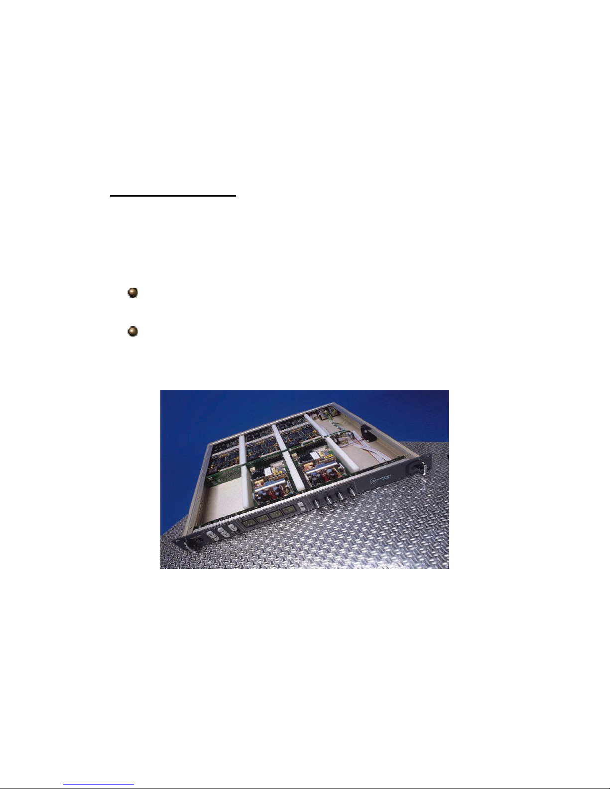
The 1RU chassis is called a Flexibox (Order code FB-9) This will hold
a maximum of 6 PM-2E/PM-4 Modules
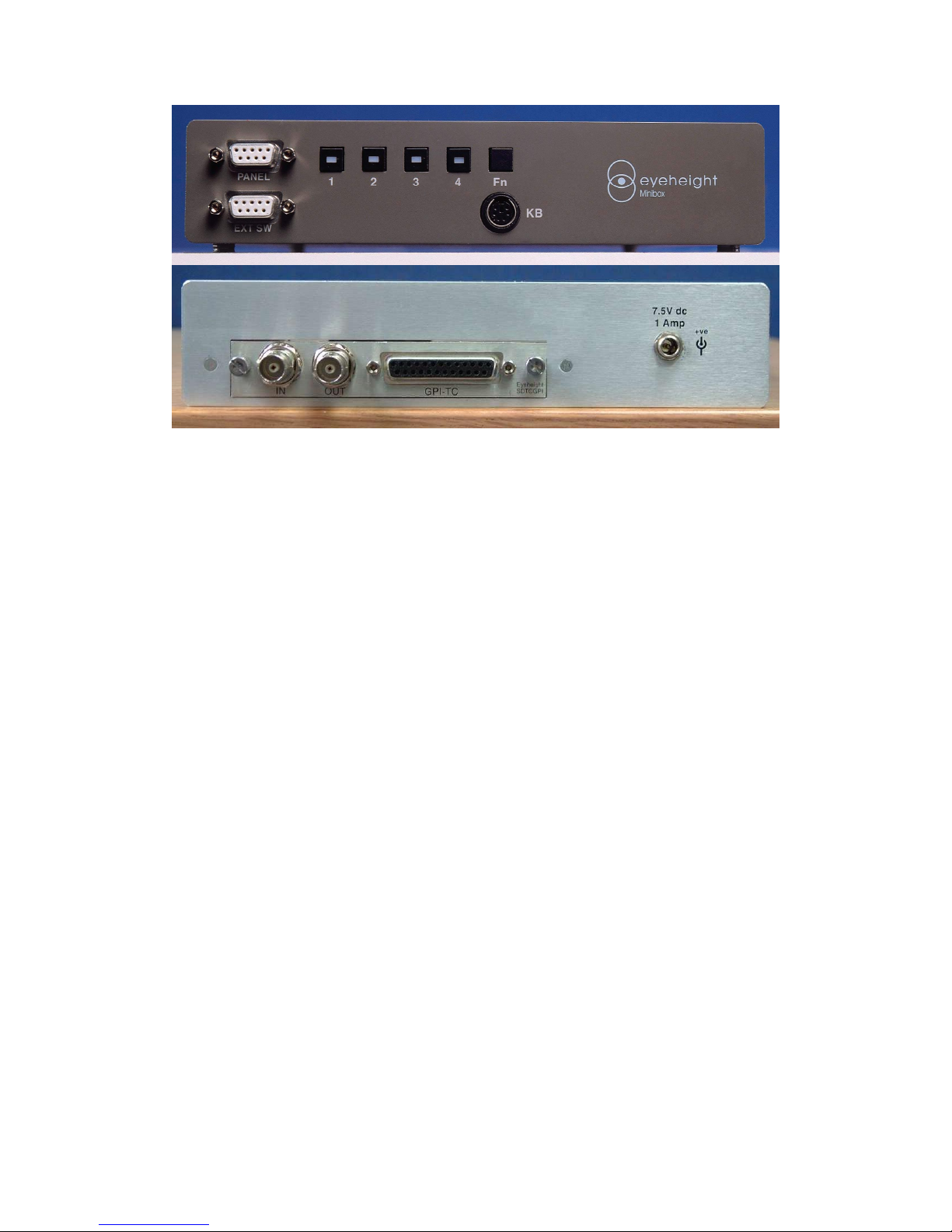
The Desktop Chassis is called a Minibox (Order code MB-9) T his will
hold one PM-2E/PM-4 Module. The Minibox has a very limited control
surface as standard. Using this control surface you can only recall the
3 Pre-set memories available on the PM-2E/PM-4.
Figure 3 Flexibox with Flexipanel fitted
Page 6
Page 6
eyeheight
Unit 34 Park House Watford Business Park Greenhill Crescent Watford Herts GB WD18 8PH
Reg. No. 2855535 Telephone: +44 (0) 1923 256 000 Fax: +44 (0) 1923 256 100 email: [email protected]
Figure 4 Minibox, Front and Rear.
Page 7

Page 7
eyeheight
Unit 34 Park House Watford Business Park Greenhill Crescent Watford Herts GB WD18 8PH
Reg. No. 2855535 Telephone: +44 (0) 1923 256 000 Fax: +44 (0) 1923 256 100 email: [email protected]
If this unit is already pre-installed in a Flexibox (FB-9) with either a local or
remote panel from the Factory then refer to the "Hardware Installation Guide"
which will be enclosed with the system. If this unit is pre-installed in a Minibox
(MB-9) also refer to the "Hardware Installation Guide" which will be enclosed
with the system
If this unit has been ordered separately we assume here that you already
have a Flexibox system with a Flexipanel and that the Flexibox has at least
two spare slots above each other for the PM-2E/PM-4 card.
To install the PM-2E/PM-4 into a flexibox it is desirable (but not necessary) to
power down the flexi-box. Follow these instructions.
1. On the rear of the flexibox are 6 slots for Products. Remove any pair of
spare blanking plates one above another. There are 2 M2.5 Screws,
which require unfastening for each blanking plate.
2. Slide the Product PCB into the spare slots and firmly push it "home".
3. Use the two thumbscrews to fasten the unit in place. Take care that the
ribbon cable for the upper circuit board stays attached to the lower
board.
4. Now refer to the "GeNETics User Guide". If your system consists of a
single Flexibox with a single Flexipanel then refer to the section titled
"Flexipanel Auto Set-up". If your system is part of a network with more
than one Flexipanel then refer to the section titled "Flexipanel Manual
Set-up". This will guide you through acquiring your product as a device
on the Flexipanel
A diagram of the Video connections for the PM-2E/PM-4 and alarm outputs is
shown below.
Installation
2
Section 1
Installation of the PM-2E/PM-4 Product
Section 2
Installing the PM-2E/PM-4 into a Flexibox
Section 3
Connecting Video to a PM-2E/PM-4
Page 8
Page 8
eyeheight
Unit 34 Park House Watford Business Park Greenhill Crescent Watford Herts GB WD18 8PH
Reg. No. 2855535 Telephone: +44 (0) 1923 256 000 Fax: +44 (0) 1923 256 100 email: [email protected]
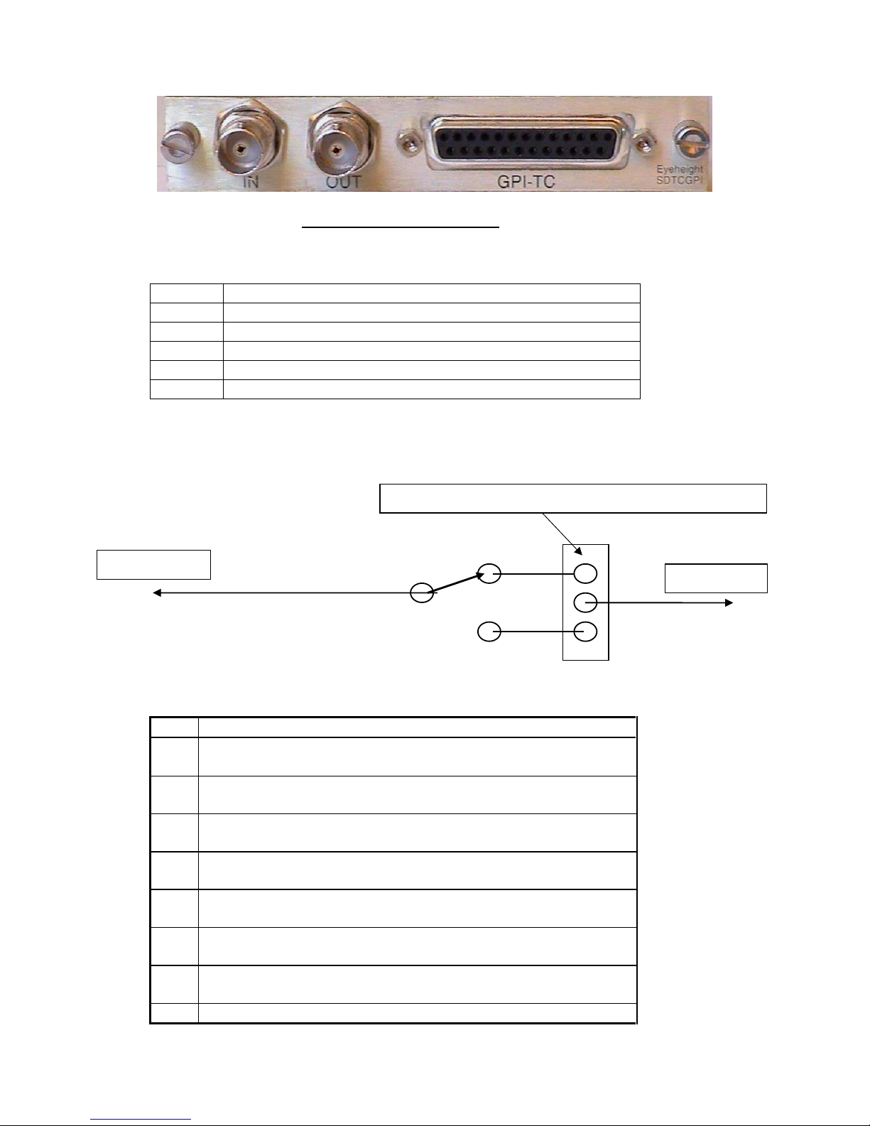
CHP-100 SDI-TC-GPI Card
Jumper Links on the Timecode and GPI I/O card
Jumper
Function
J2 Set to the Right, SDI Jitter Filtering selection
LK1 Set to Top, Polarity selection for GPI Relay Output#1
LK2 Set to Top, Polarity selection for GPI Relay Output#2
LK3 Set to Top, Polarity selection for GPI Relay Output#3
LK4 Set to Top, Polarity selection for GPI Relay Output# 4
Diagram of a GPI Output (GPI14)
Rear 25W D-Type connection (AUX)
Pin#
Function
1. General Purpose Output #1a (GPO1a). Isolated Relay
closure. AUDIO ALARM
2. General Purpose Output #1b (GPO1b). Isolated Relay
closure.
3. General Purpose Output #2a (GPO2a). Isolated Relay
closure AUDIO ALARM ACCEPT
4. General Purpose Output #2b (GPO2b). Isolated Relay
closure
5. General Purpose Output #3a (GPO3a). Isolated Relay
closure
6. General Purpose Output #3b (GPO3b). Isolated Relay
closure
7. General Purpose Output #4a (GPO4a). Isolated Relay
closure.
8. General Purpose Output #4b (GPO4b). Isolated Relay
Pin 1,3,5,7
Pin 2,4,6,8
Jumpers LK1
4, set the polarity of the relay
Page 9

Page 9
eyeheight
Unit 34 Park House Watford Business Park Greenhill Crescent Watford Herts GB WD18 8PH
Reg. No. 2855535 Telephone: +44 (0) 1923 256 000 Fax: +44 (0) 1923 256 100 email: [email protected]
closure.
9. General Purpose Output #5 (GPO5). Open Collector
Output (<100mA)
10. General Purpose Output #6 (GPO6). Open Collector
Output (<100mA)
11. General Purpose Output #7 (GPO7). Open Collector
Output (<100mA)
12. General Purpose Output #8 (GPO8). Open Collector
Output (<100mA)
13. General Purpose Input #1 (GPI1). Pull to Ground to
activate. ACCEPT ALARM.
14. General Purpose Input #2 (GPI2). Pull to Ground to
activate.
15. General Purpose Input #3 (GPI3). Pull to Ground to
activate.
16. General Purpose Input #4 (GPI4). Pull to Ground to
activate.
17. General Purpose Input #5 (GPI5). Pull to Ground to
activate.
18. General Purpose Input #6 (GPI6). Pull to Ground to
activate.
19. General Purpose Input #7 (GPI7). Pull to Ground to
activate.
20. General Purpose Input #8 (GPI8). Pull to Ground to
activate.
21. Time Code Input (LTC) Balanced (+)
22. Time Code Input (LTC) Balanced (-)
23.
24.
25. GND
Page 10
Page 10
eyeheight
Unit 34 Park House Watford Business Park Greenhill Crescent Watford Herts GB WD18 8PH
Reg. No. 2855535 Telephone: +44 (0) 1923 256 000 Fax: +44 (0) 1923 256 100 email: [email protected]
Control of the PM-2E/PM-4 is generally done using an FP-9 Flexi panel. It is
also possible to control this unit with a n FP-10 Panel (Desktop Panel) or if the
unit is mounted in a Mini-Box limited control will be available with the mini-box
Preset select buttons which will have been pre-set at the factory. The unit can
also be controlled remotely using a PC running the Softpanel software.
The PM-2E/PM-4 is, as are all genetics modules, controlled using a set of
MENUS. Each of these menus contains up to 3 parameters that are adjusted
using the rotary digipots. The Menus define all of the adjustable operational
parameters in the PM-2E/PM-4. Pressing the rotary di gipots brings the
parameter to its default value. Device selection is done using the device
select switches which, when pressed, will offer the name of the device in the
LCD Window. Modules can be acquired and then de-acquired using the setup switch. For a full description of the operation philosophy of the GeNETics
system refer to the “geNETics User Guide” (section “Operation of the
Flexipanel”)
A full list of the Menus and their functions are given in section 3 of this
chapter.
The following set of menus defines the operation of the PM-2E/PM-4. Some of
the menus below only apply for the PM-2E/PM-4 and PM-2E/PM-4E units.
This is indicated
Operation
3
Section 1
Control of the PM-2E/PM-4
Section 2
Operational Menus for the PM-2E/PM-4
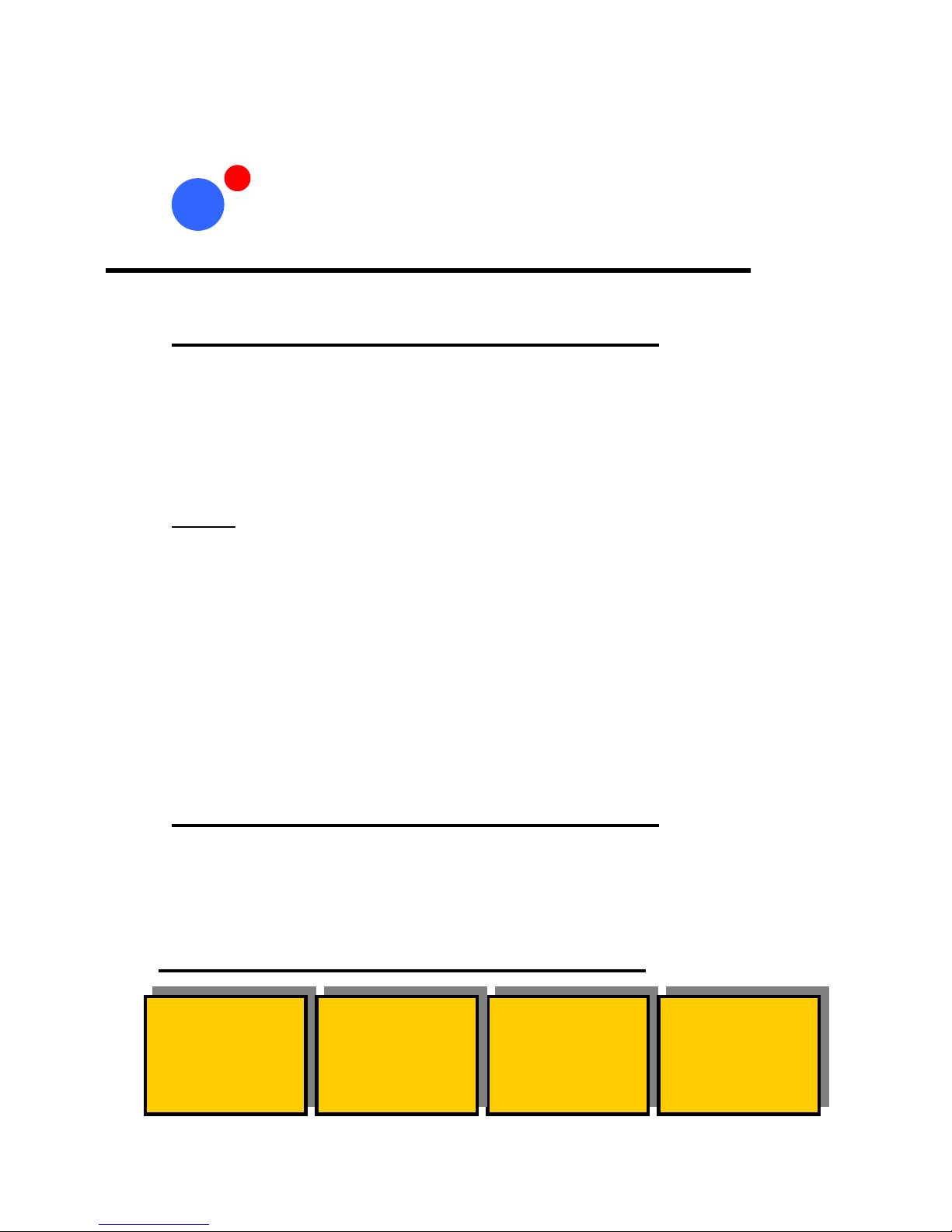
Menus 00
-
03
Top Level Menus
------
AUDIO
------
-----DSPLAY
------
-----METER
------
------
SYSTEM
------
Page 11
Page 11
eyeheight
Unit 34 Park House Watford Business Park Greenhill Crescent Watford Herts GB WD18 8PH
Reg. No. 2855535 Telephone: +44 (0) 1923 256 000 Fax: +44 (0) 1923 256 100 email: [email protected]
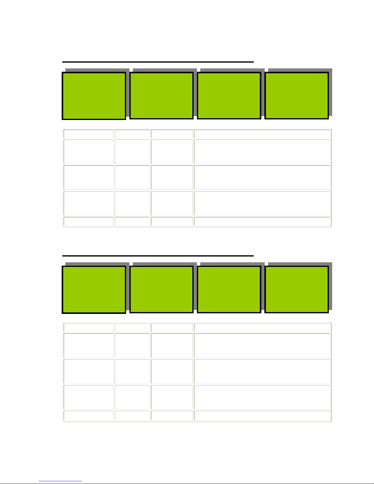
Menu Num. Heading Automation Function
4 Audio
Bars
Off,On
Default is
On
Pressing this will turn on or off the Audio
Bars
5 Audio
Scale
Off,On
Default is
On
Pressing this will draw or clear the audio
scales.
6 Ovrlay
level
0-100%
Default is
100
The fade level of the audio bars and audio
scales.
7 SPARE
Menu Num. Heading Automation Function
8 Audio
Bar
Vert, Horz
Default is
Vertical
Selects whether the audio bard are
horizontal or vertical.
9 Audio
size
1/7 to Full
default is
Full
The length of the audio bars. The
following options are available 1/7, 1/6,
1/5, ¼, 1/3, ½ and Full.
10 Audio
Width
1-999
Default is
10
The width of the
11 SPARE
Menus 04
-
07
Top Level Menus
Audio
Bars
=On
Ovrlay
Level
=75%
Audio
Scale
=On
Menus 08
-
11
Top Level Menus
Audio
Bar
=Vert
Audio
Width
=10
Audio
Size
=Full
Page 12
Page 12
eyeheight
Unit 34 Park House Watford Business Park Greenhill Crescent Watford Herts GB WD18 8PH
Reg. No. 2855535 Telephone: +44 (0) 1923 256 000 Fax: +44 (0) 1923 256 100 email: [email protected]
Menu Num. Heading Automation Function
20 Ident
H posn
0-999
Default is
15
This sets the horizontal position of the
Ident bar on the video image.
21 Ident
V posn
0-999
Default is
65
This sets the vertical position of the of the
Ident bar on the video image.
22 Text
H size
0-2,
Default is 1
This sets the horizontal size of the text.
23 Text
V size
0-1,
Default is 0
This sets the vertical size of the text.
Menus 20
-
23
Top Level Menus
Ident
H posn
=15
Text
H size
=1
Ident
V posn
=65
Text
V size
=0
Page 13
Page 13
eyeheight
Unit 34 Park House Watford Business Park Greenhill Crescent Watford Herts GB WD18 8PH
Reg. No. 2855535 Telephone: +44 (0) 1923 256 000 Fax: +44 (0) 1923 256 100 email: [email protected]
Technical Specification for the PM-2E/PM-4
Number of Inputs 1
Type of Inputs 270Mbit Serial Digital Video Inputs 75 Ohm
Line Length At least 200 Meters of PSF1/3 (Typically 275 Meters)
Number of Outputs 3 Output BNC’s per Card (Configurable).
Type Of Outputs 270Mbit Serial Digital Video Outputs, 75 Ohm, 800mV
Total Number Of
BNC Connections
5, consisting of 1 Fixed Input and 3 Jumper
Configurable outputs. (One BNC not used)
SDI Output Jitter The system will add less than 0.2UI to the input Jitter.
(This is only guaranteed on issue 2 or later cards)
Current Consumption <800mA at +5V
Size 215mm by 100mm
Jumpering the I-BUS (CAN-BUS) Termination
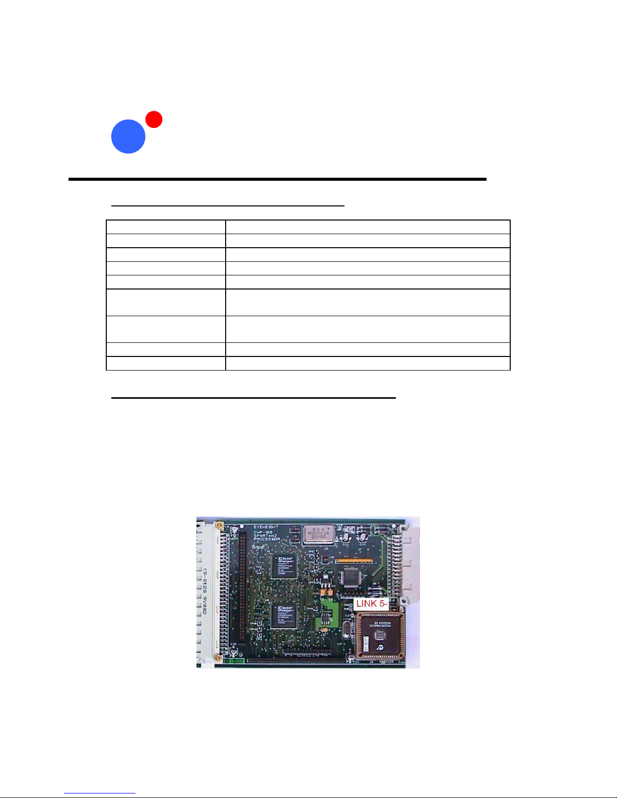
The I-BUS Network is the "control system" under which all Products and
Panels are networked together. Under certain circumstances it is necessary to
terminate the network. This can be done on a Panel or a "Product". To
terminate this product, locate J5 on the PM-2E/PM-4 Processor Card supplied
which is between U1 (The large square "chip") and the Edge connector. (This
is on the half of the card labelled "CHP-100 Spartan2 Processor"). Jumper
this with a 2mm link.
Figure 5 Location of I-bus termination link
Technical Appendix
4
 Loading...