

Page 1
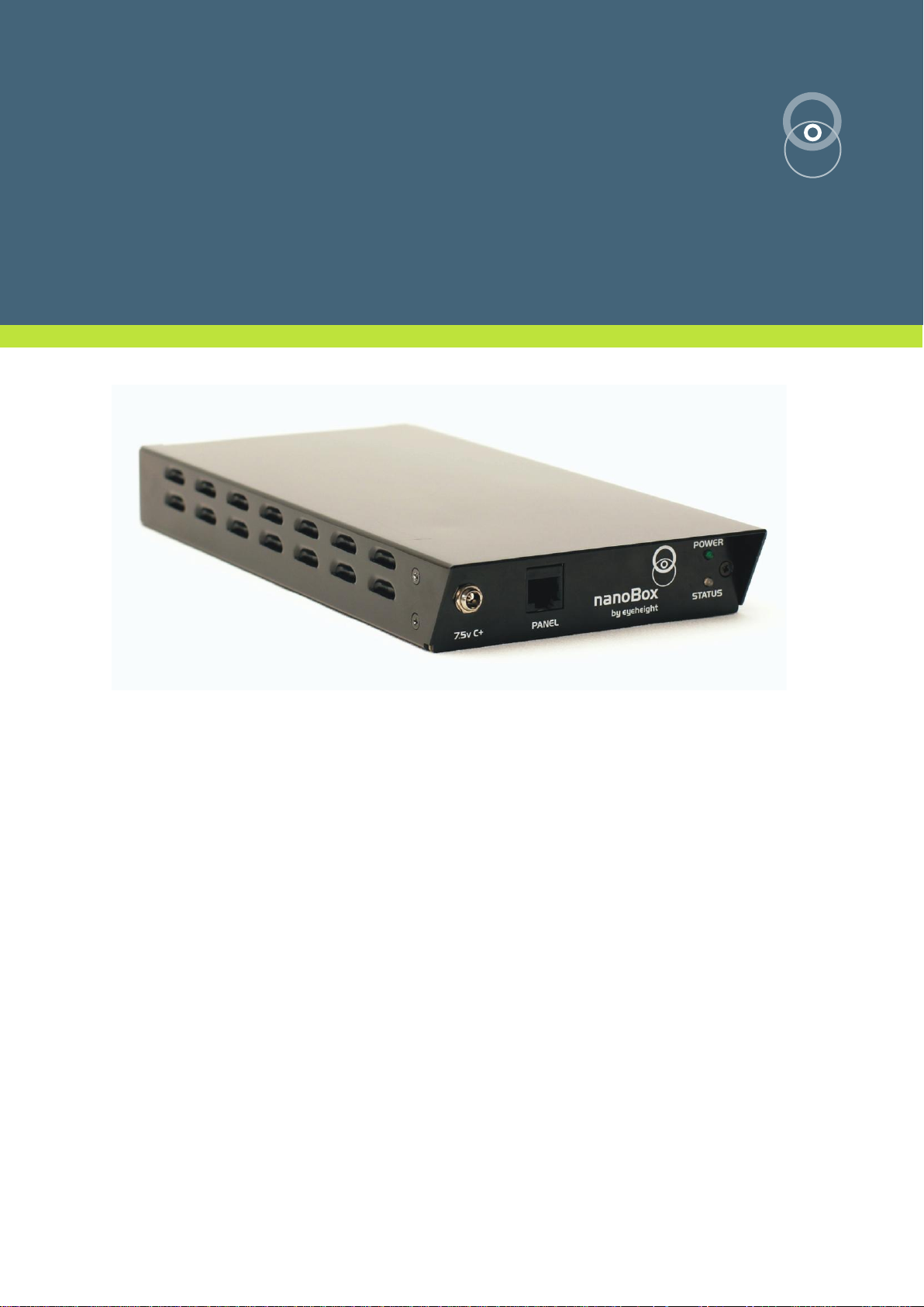
AR-2n
Multimode Aspect Ratio Converter in a desktop chassis with
software control application.
user manual
eyeheight
Page 2
Eyeheight Limited, Sutton Business Centre, Restmor Way, Wallington, Surrey SM6 7AH
Reg. No. 2855535 Telephone: +44 (0) 208 255 2015 Fax: +44 (0) 208 241 6951 email: [email protected]
User Manual Versions
Date
Product
Version
MD S/W
Version
MD F/W
Version
Viper
Version
Changed
13/06/2008
AR-2 V100
AR-2 S104
AR-2MD
F100
V100
17/06/2008
AR-2 V101
AR-2 S106
AR-2MD
F100
V100
- fixed bug with x-fade not being updated when changed
- fixed infinite loop issue with fade to black and invalid input
video/powerup condition
25/06/2008
AR-2 V102
AR-2 S106
AR-2MD
F101
V100
added 507->487 remapping nd fixed hd audio CRC error
06/08/2008
AR-2 V103
AR-2 S106
AR-2MD
F101
V101
fixed numerous issues with VIPER build 100, rest no change
02/10/2008
AR-2MD
V104
AR-2MD
S117
AR-2MD
F113
V106
HD audio fixed, many software changes, many viper changes
14/10/2008
AR-2MD
V105
AR-2MD
S118
AR-2MD
F113
V106
Fixed issue with GPI changes setting variable in incorrect bank
22/10/2008
AR-2MD
V106
AR-2MD
S119
AR-2MD
F113
V106
Fixed bug that caused a memory to be saved in the wrong
location
Fixed a banking error with the simple protocol
07/11/2008
AR-2MD
V107
AR-2MD
S120
AR-2MD
F113
V106
fixed a couple of small issues, see log for details
Versions
Changes
Date
Software
1.0
Initial release
17/6/09
V106
1.1
Softpanel instructions re-directed
01/02/10
V106
- 2 -
Page 3

Eyeheight Limited, Sutton Business Centre, Restmor Way, Wallington, Surrey SM6 7AH
Reg. No. 2855535 Telephone: +44 (0) 208 255 2015 Fax: +44 (0) 208 241 6951 email: [email protected]
Table of Contents
Table of Contents .................................................................................................. 3
Table of Figures .................................................................................................... 5
1 System Overview ............................................................................................... 6
1.1 The nanobox chassis .............................................................................. 6
1.2 The AR-2n product. ................................................................................. 6
2 Setting up the AR-2n ......................................................................................... 8
2.1 Associated equipment. ............................................................................ 8
2.2 Connecting the LE-2n using a soft panel. ............................................... 8
2.2.1 Installing the software. ......................................................................... 9
2.3 Screen Layout ....................................................................................... 10
2.3.1 Toolbar ............................................................................................... 10
2.3.2 Device Info. ........................................................................................ 11
2.3.3 Status Bar .......................................................................................... 11
2.3.4 Display Buttons .................................................................................. 11
2.3.5 Rotary Controls .................................................................................. 12
2.3.6 Next & Previous Buttons .................................................................... 12
2.4 Menu Navigation ................................................................................... 12
2.4.1 Go To Another Menu ......................................................................... 13
2.4.2 Single Parameter Adjustment ............................................................ 13
2.4.3 Double Or Triple Parameter Adjustment ............................................ 13
2.4.4 Information Display ............................................................................ 13
2.5 Connecting the AR-2n using an FP-9. .................................................. 13
2.5.1 Flexipanel controls. ............................................................................ 15
2.5.2 Device Buttons. .................................................................................. 15
2.5.3 Menu Navigation. ............................................................................... 15
2.5.4 Parameter adjustment of a green menu. ............................................ 15
2.5.5 Parameter adjustment of a red menu ................................................. 16
2.5.6 Information display ............................................................................. 16
3 Connecting Video to the AR-2n ........................................................................ 17
4 Other Features/Messaging ............................................................................... 18
4.1 Messaging with the soft java panel. ...................................................... 18
- 3 -
Page 4

Eyeheight Limited, Sutton Business Centre, Restmor Way, Wallington, Surrey SM6 7AH
Reg. No. 2855535 Telephone: +44 (0) 208 255 2015 Fax: +44 (0) 208 241 6951 email: [email protected]
4.2 Messaging with an FP-9........................................................................ 18
4.3 Tamper Locking the AR-2n. .................................................................. 19
4.4 Primary AR-2N control .......................................................................... 19
4.4.1 Setting the output video standard ...................................................... 19
4.4.2 Bypass mode operation ..................................................................... 19
4.4.3 Loading a memory ............................................................................. 20
4.4.4 Setting up the GPIs ............................................................................ 22
4.4.5 Setting up embedded video signalling parameters ............................ 23
4.4.6 Setting up the transition parameters .................................................. 23
4.4.7 Setting the power-on default values ................................................... 24
4.5 Advanced AR-2N control ...................................................................... 24
4.5.1 Adjusting the output picture dimensions ............................................ 24
4.5.2 Adjusting the input picture blanking ................................................... 25
4.5.3 Setting the Audio delay ...................................................................... 25
4.5.4 Adjusting the advanced video options ................................................ 26
4.5.5 Auto-ARC mode and the Clear all vars function ................................ 27
4.5.6 Saving a user memory ....................................................................... 28
4.5.7 Viewing a saved memory ................................................................... 30
4.6 The software upgrade process .............................................................. 31
4.7 Unit reset options .................................................................................. 31
5 The AR-2N Menu Set ....................................................................................... 33
6 Technical Appendix .......................................................................................... 71
6.1 GPI/Tally/RS232 technical information. ................................................ 71
6.1.1 GPI Inputs. ......................................................................................... 71
6.1.2 GPI Splitter ........................................................................................ 72
6.2 Technical Specifications ....................................................................... 73
6.3 Aspect Ratio Terminology ..................................................................... 75
- 4 -
Page 5

Eyeheight Limited, Sutton Business Centre, Restmor Way, Wallington, Surrey SM6 7AH
Reg. No. 2855535 Telephone: +44 (0) 208 255 2015 Fax: +44 (0) 208 241 6951 email: [email protected]
Table of Figures
Figure 1-1 Figure 1 1 Nanobox chassis with worldwide PSU and USB Cable ...... 6
Figure 1-2 The AR-2n Front (top) and Rear (below). ............................................ 7
2-1 Diagram showing the power and data connections. ........................................ 9
2-2 LE-2n Power and control connection using an FP-9. .................................... 14
Figure 2-3 Flexipanel (FP-9) controls. ................................................................. 15
Figure 2-4 Types of menus showing their characteristic colours ......................... 15
Figure 3-1 - Video connections to the AR-2N ...................................................... 17
Figure 3-2 AR-2n Connections. ........................................................................... 17
Figure 4-1 UK keyboard reference diagram. ....................................................... 18
Figure 6-1 Typical GPI Input ............................................................................... 71
Figure 6-2 GPI Splitter. Has 2 RJ-45 Sockets, one for the Comms and one for the
GPI's ............................................................................................................ 72
- 5 -
Page 6
Eyeheight Limited, Sutton Business Centre, Restmor Way, Wallington, Surrey SM6 7AH
Reg. No. 2855535 Telephone: +44 (0) 208 255 2015 Fax: +44 (0) 208 241 6951 email: [email protected]
1 System Overview
This manual describes the function of the AR-2n which is an AR-2S (SD-SDI) or
AR-2M (SD/HD-SDI) Aspect Ratio Converter (from now on referred to as ARC)
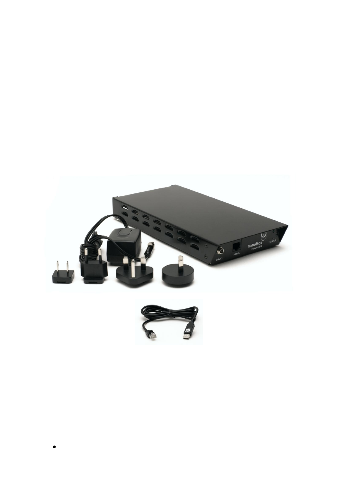
processing card connected within a nanobox desktop chassis.
1.1 The nanobox chassis
The nanobox chassis has been designed to provide a low cost way of operating a
single ARC card for stand-alone use without the complex and more expensive
infrastructure of an etherbox 1RU rack mount chassis (FB-9E) and 1RU
operational panel (FB-9). The AR-2n ARC card is operated by a java software
application for PC or MAC. Connection is via a supplied USB lead.
Figure 1-1 Figure 1 1 Nanobox chassis with worldwide PSU and USB Cable
1.2 The AR-2n product.
The AR-2n is a single channel aspect ratio converter and up/down-converter,
incorporating HD/SD auto-sensing and 3 field temporal processing. It is capable
of high quality bi-directional conversion between different aspect ratios such as
4:3, 14:9, 16:9, etc. with full 10-bit resolution.
In addition to the basic function of the AR-2n listed above, the unit also has the
following features:
WSS/VI control
- 6 -
Page 7

Eyeheight Limited, Sutton Business Centre, Restmor Way, Wallington, Surrey SM6 7AH
Reg. No. 2855535 Telephone: +44 (0) 208 255 2015 Fax: +44 (0) 208 241 6951 email: [email protected]
Blanking adjustments
Integrated embedded audio delay which compensates for internal and
external picture delay, settable from a control panel.
InvisiARC™ technology for discrete aspect ratio switching
Advanced filter controls including Mosquito Noise Reduction and Block
Artefact Removal
Figure 1-2 The AR-2n Front (top) and Rear (below).
- 7 -
Page 8

Eyeheight Limited, Sutton Business Centre, Restmor Way, Wallington, Surrey SM6 7AH
Reg. No. 2855535 Telephone: +44 (0) 208 255 2015 Fax: +44 (0) 208 241 6951 email: [email protected]
2 Setting up the AR-2n
2.1 Associated equipment.
The AR-2n can operate in two modes. Each of these modes is determined by a
factory set internal link option. The modes are:
1. Operation using a soft panel on a PC or a Mac computer.
2. Operation using a “hard” eyeheight FP-9 Flexipanel.
Respectively the associated equipment required for operation of the above
modes are:
1. A PC or Mac to operate the softpanel. (User provided) and a USB cable
(Supplied).
2. An FP-9 control panel with an RR-9E rear enclosure (Available from
eyeheight) and a standard ethernet cable with RJ-45 connectors (user
supplied) is also required to connect the FP-9 panel to the AR-2n.
The AR-2n will always be shipped in mode 1 ( Soft Panel) unless the
customer specifies otherwise.
DO NOT CONNECT THE SUPPLIED USB/RJ45 CABLE TO THE
FRONT RJ45 LABELLED “PANEL” THIS COULD RESULT IN
DAMAGE TO THE UNIT.
You cannot operate the softpanel and an FP-9E Flexipanel at the
same time.
2.2 Connecting the LE-2n using a soft panel.
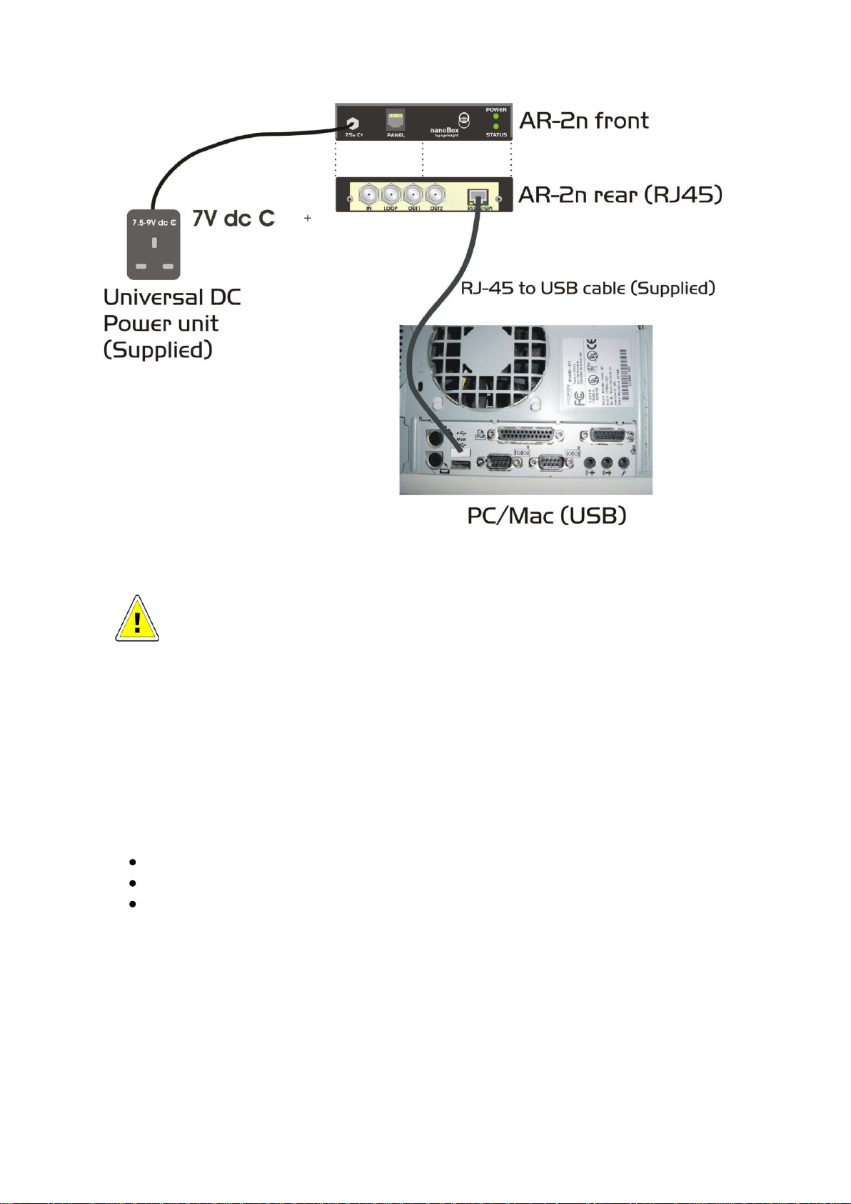
This is the way the LE-2n is normally shipped. The data and power connections
are shown in the diagram below. After power up the Status light should turn from
red to green indicating that it is operational in soft panel mode. If the status light
goes orange the system was factory configured for operation with an FP-9 1RU
panel. In the unlikely event that the status light stays red then the system has
found an error and it will need returning to the factory.
- 8 -
Page 9
Eyeheight Limited, Sutton Business Centre, Restmor Way, Wallington, Surrey SM6 7AH
Reg. No. 2855535 Telephone: +44 (0) 208 255 2015 Fax: +44 (0) 208 241 6951 email: [email protected]
2-1 Diagram showing the power and data connections.
THE AR-2n UNIT MUST BE PLACED IN A COOL ENVIROMENT
(ROOM TEMPERATURE IS REASONABLE) WITH ADAQUATE
VENTELATION. DO NOT COVER OR USE IN AN UNVENTELATED
RESTRICTED SPACE.
2.2.1 Installing the software.
The software is provided on an eyeheight USB flash drive which is supplied with
the LE-2n.
The softPanel application requires no installation itself. Simply run “softpanel.jar”
However, it requires three platforms to be in place already:
Java Runtime Environment (Java 5 or later).
RxTx serial drivers for Java (see below).
USB to serial drivers.
For full installation instructions please refer to the softPanel_manual_20xx.pdf
which is available by selecting:
Support -> Manuals -> Software on our website at Eyeheight.com and is also
supplied on the memory stick which comes with the AR-2n.
- 9 -
Page 10
Eyeheight Limited, Sutton Business Centre, Restmor Way, Wallington, Surrey SM6 7AH
Reg. No. 2855535 Telephone: +44 (0) 208 255 2015 Fax: +44 (0) 208 241 6951 email: [email protected]
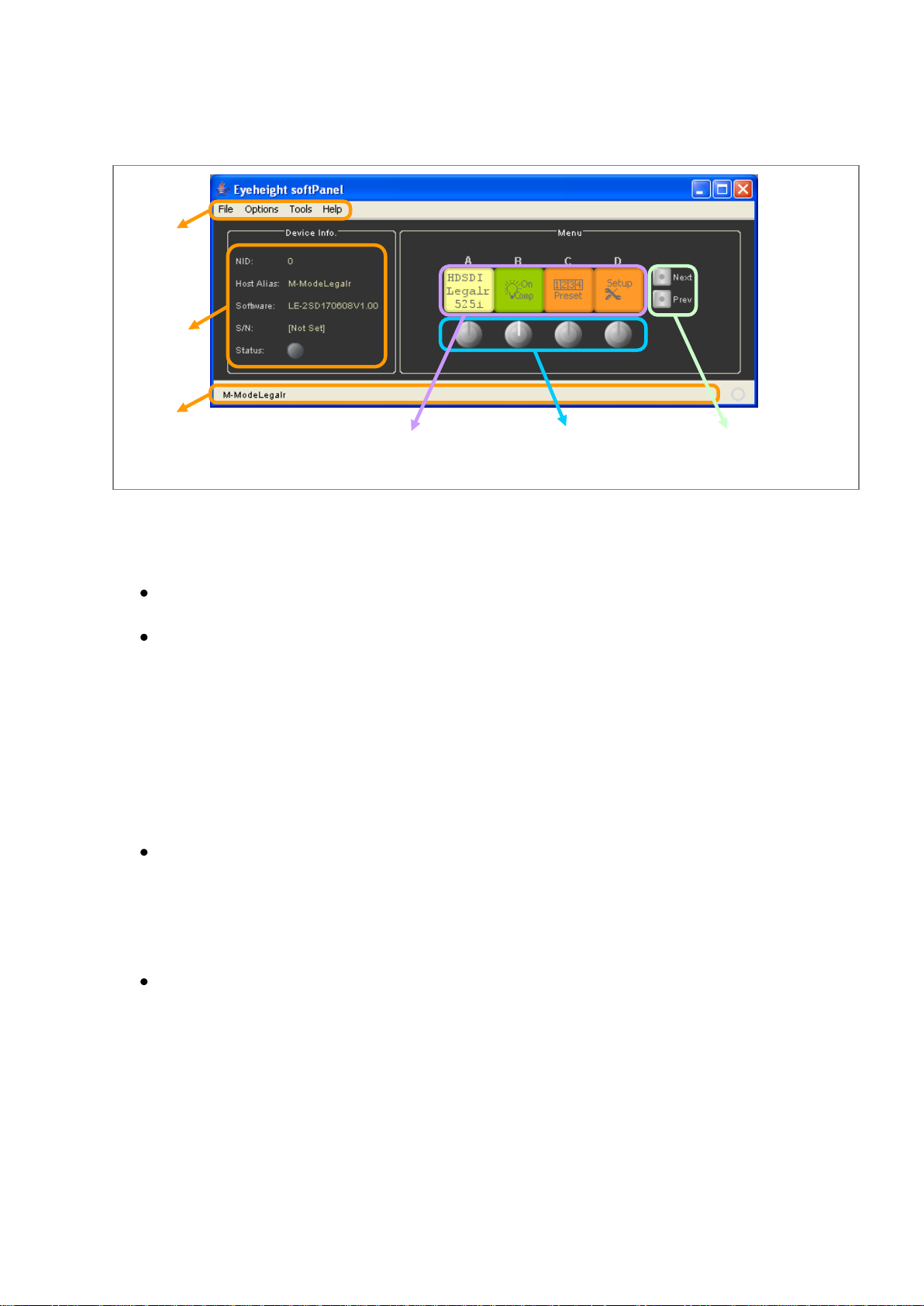
2.3 Screen Layout
Toolbar
Device
Info.
Status
Bar
Display
Buttons
Rotary
Controls
Next & Previous
Buttons
2.3.1 Toolbar
File
o Exit
Options
o COM Port
Tick the name of the COM Port that you want to use.
The application will enumerate this list of your COM Ports when it
starts up.
o Baud Rate
This is the speed of the serial comms. You will need to use 115200.
o Large Displays
If you find the Display Buttons too small, then you can tick this
option to increase the size at the expense of the resolution.
Multi-Device Mode
If you are using the softPanel with a nanoBox (NB-9), you will not need to
set this option.
This option should be set if you are using the softPanel with an etherBox
(FB-9E) to control more than one product, as you would a standard panel
(FP-9).
Tools
o Refresh
The softPanel will request a menu refresh from the active device.
It will also refresh the data displayed in the Device Info box.
o Send Message
The messaging system is used to send text messages from the
panel to a product.
For more info, see section 4.
o Un-acquire product
Like a standard Eyeheight panel (e.g., FP-9), the softPanel
- 10 -
Page 11

Eyeheight Limited, Sutton Business Centre, Restmor Way, Wallington, Surrey SM6 7AH
Reg. No. 2855535 Telephone: +44 (0) 208 255 2015 Fax: +44 (0) 208 241 6951 email: [email protected]
“acquires” control of a product, and retains a lock to prevent other
panels from controlling the same device.
To release that lock, and allow other panels to control the device,
use this tool.
o Search for products…
Scans the Eyeheight system for available products, and adds them
to the Devices list.
Help
o About…
Shows version number, release, and development information.
2.3.2 Device Info.
Shows information about the device that you are controlling, to identify it and
display status information.
NID
The Network ID is an address on the Eyeheight I-Bus communication
network.
Host Alias
Sometimes known as the username, this is a user definable identification,
saved to the product
Software
The version of software that the device is running.
By convention, this is commonly formed from [product name] + [release
date] + [version number].
S/N
Serial Number of the device. This uniquely identifies the product.
Status
This control will display according to the status of the device.
The display colour is based on a traffic light system of green, amber, and
red.
Hover the mouse over the control to see an information tooltip.
2.3.3 Status Bar
Generic GUI component, for conveying information to the user.
In normal use, the status bar will display the Host Alias of the device, but it is also
used to display error messages and status updates.
2.3.4 Display Buttons
The four buttons, labelled A, B, C, and D act both as separate menu displays,
and as larger combined displays, depending on context.
- 11 -
Page 12
Eyeheight Limited, Sutton Business Centre, Restmor Way, Wallington, Surrey SM6 7AH
Reg. No. 2855535 Telephone: +44 (0) 208 255 2015 Fax: +44 (0) 208 241 6951 email: [email protected]
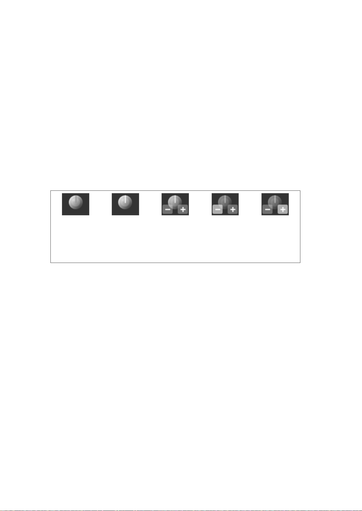
They also act as buttons; performing an action when clicked. This action will
Not enabled
Enabled
Mouse
hovered over
centre
Mouse
hovered over
minus button
Mouse
hovered over
plus button
depend on what is displayed on the button at the time.
For more info, see Menu Navigation.
2.3.5 Rotary Controls
In normal use, the four rotary controls correspond directly with the four Display
Buttons; each to the display above it.
When a rotary control is not enabled, its marker will be grey.
When it is in use, the marker will be white, and it will respond to the mouse
pointer, when hovered over it:
Click the plus button to rotate clockwise (increment).
Click the minus button to rotate anti-clockwise (decrement).
The centre button usually restores a menu to its default value.
2.3.6 Next & Previous Buttons
These are aids to navigating the devices “flat” menu systems.
They flash while further menus are available.
2.4 Menu Navigation
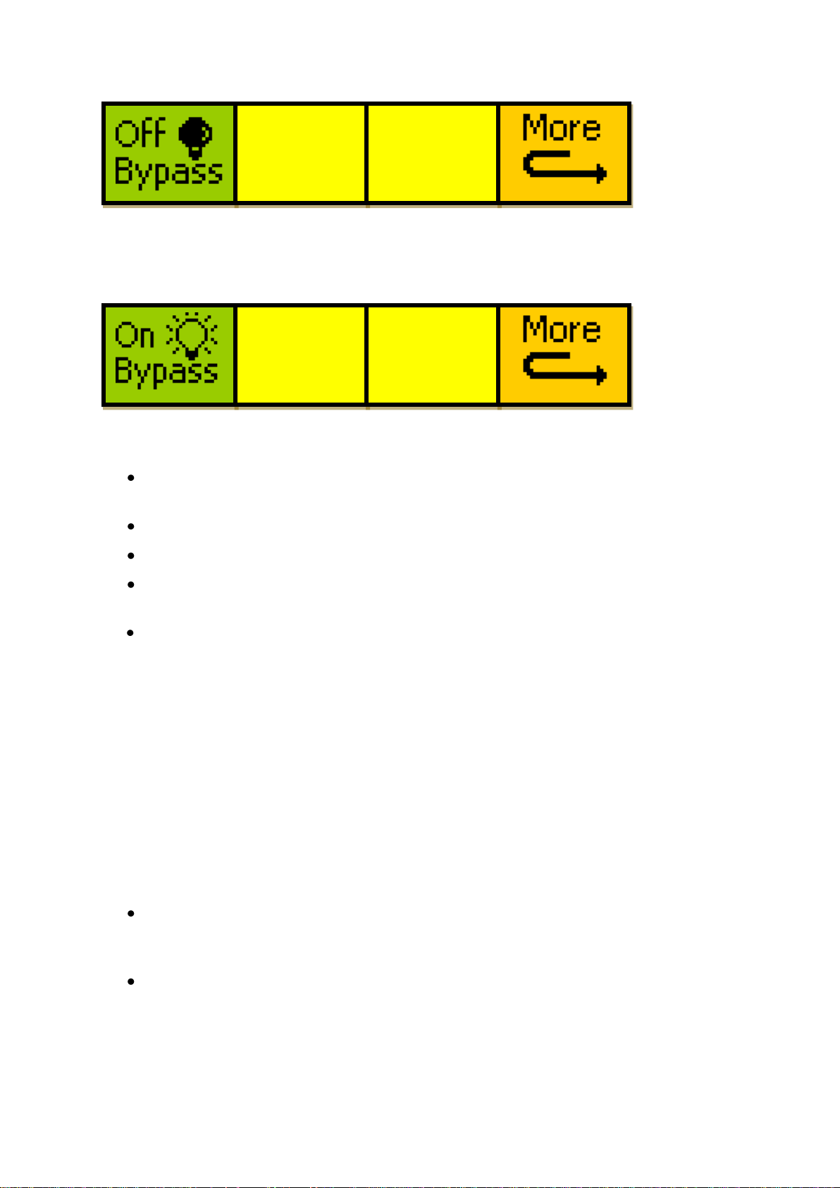
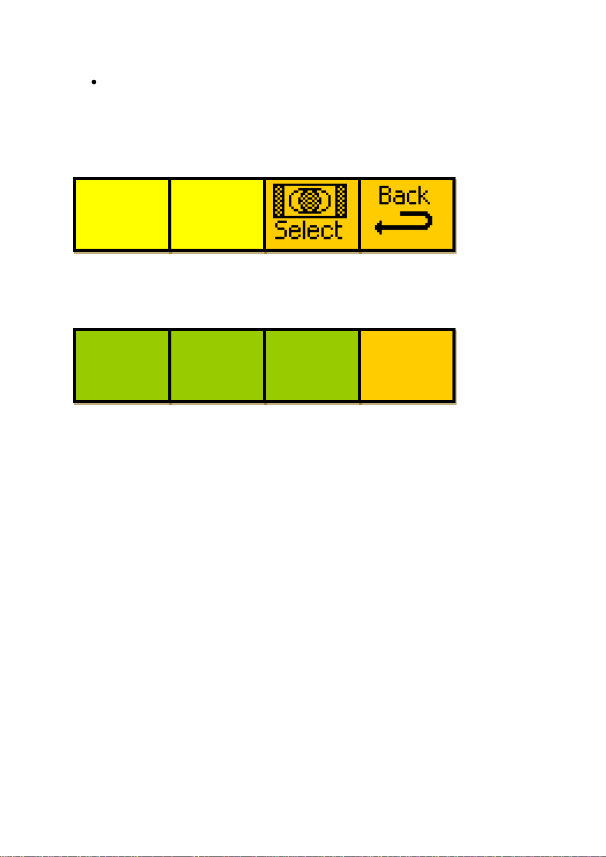
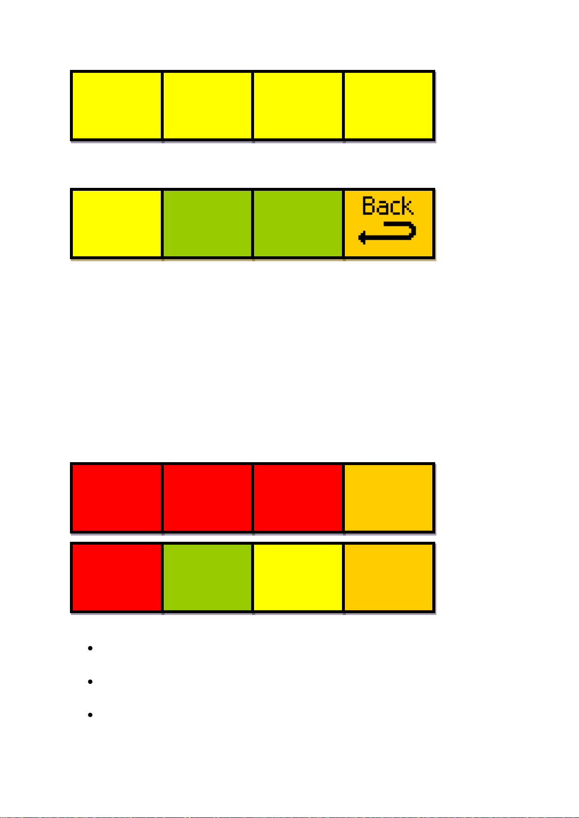
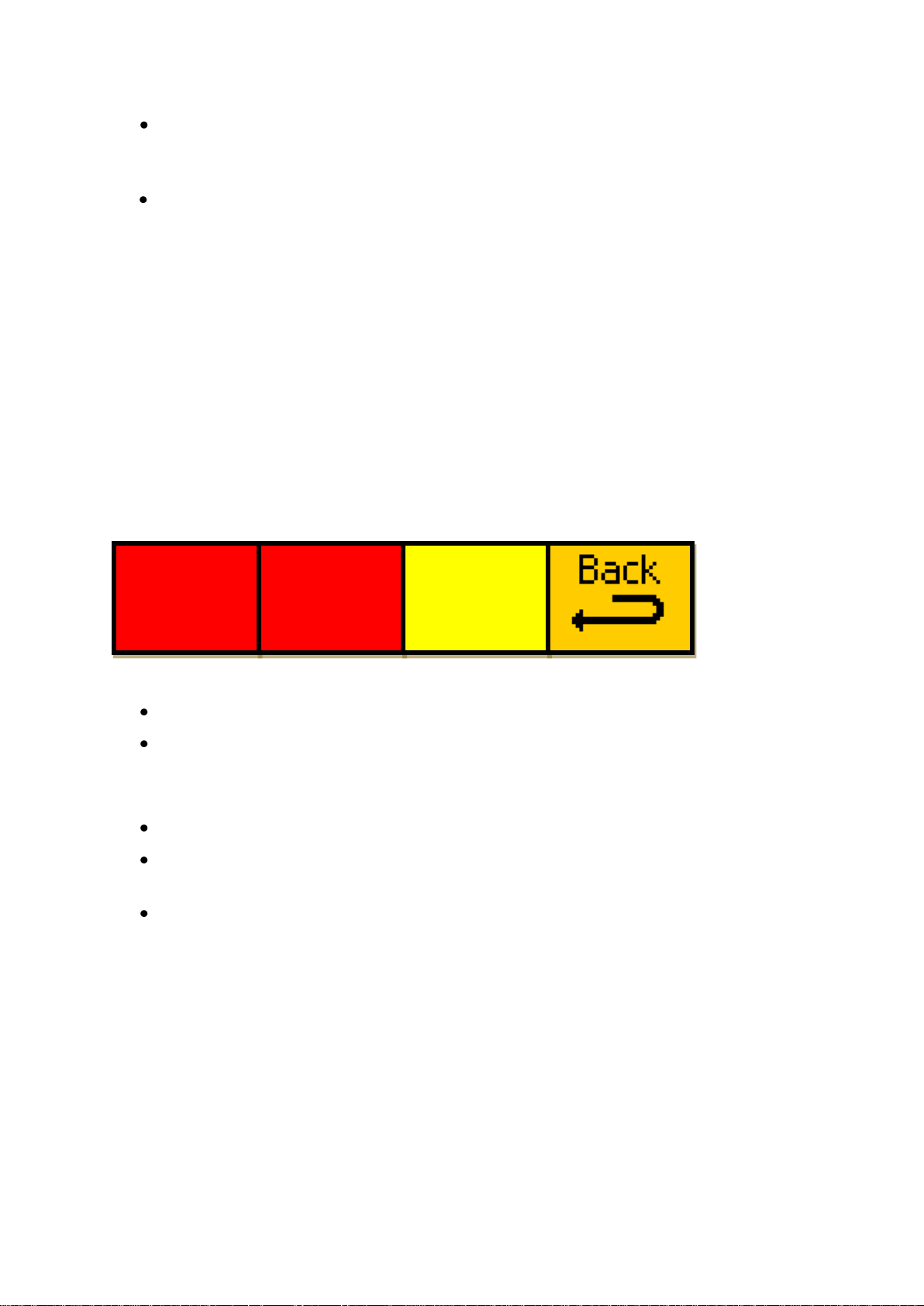
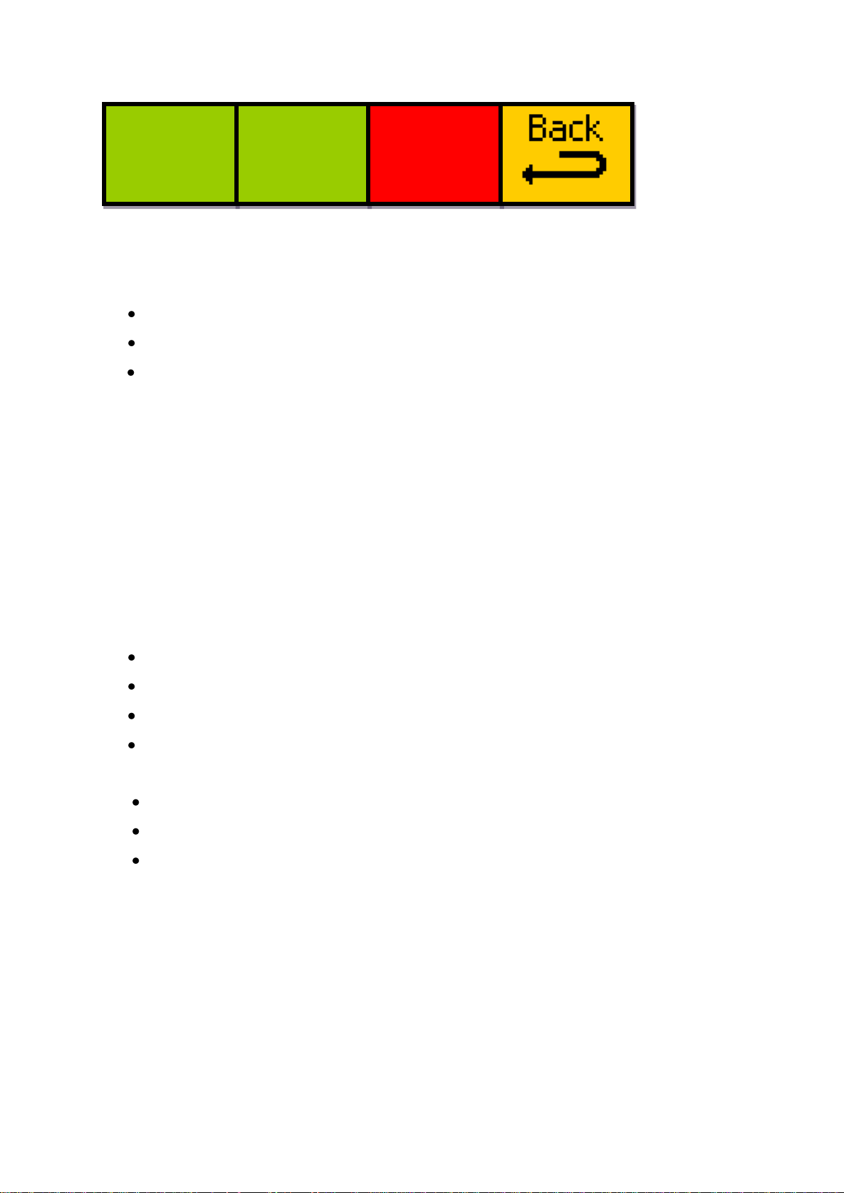
Menus are colour coded to show how to interact with them.
- 12 -
Page 13

Eyeheight Limited, Sutton Business Centre, Restmor Way, Wallington, Surrey SM6 7AH
Reg. No. 2855535 Telephone: +44 (0) 208 255 2015 Fax: +44 (0) 208 241 6951 email: [email protected]
See below:
Go To
Another Menu
Single
Parameter
Adjustment
Double Or
Triple
Parameter
Adjustment
Information
Display
2.4.1 Go To Another Menu
A common menu item, used for navigating tree-structured menus.
2.4.2 Single Parameter Adjustment
A green menu is one in which there is one adjustable parameter.
There are two ways to adjust the parameter in a green menu:
Press the green Display Button.
This will increment the value in that window.
This is most frequently done when the menu parameter is Textural for
example switching a parameter between ON and OFF. In this case a
button press is most natural.
Use the Rotary Controls to adjust the parameter in the respective Display
Button.
The direction and speed of rotation enable numeric values to be set easily.
2.4.3 Double Or Triple Parameter Adjustment
A red menu is one in which there are two or three adjustable parameters. In this
case it is necessary to first select the menu by pressing the red Display Button.
When the red button is pressed it will turn green, and either two or three of the
Rotary Controls will flash, indicating that the respective Rotary Control will
operate a corresponding parameter.
2.4.4 Information Display
A yellow menu is one in which only information is displayed.
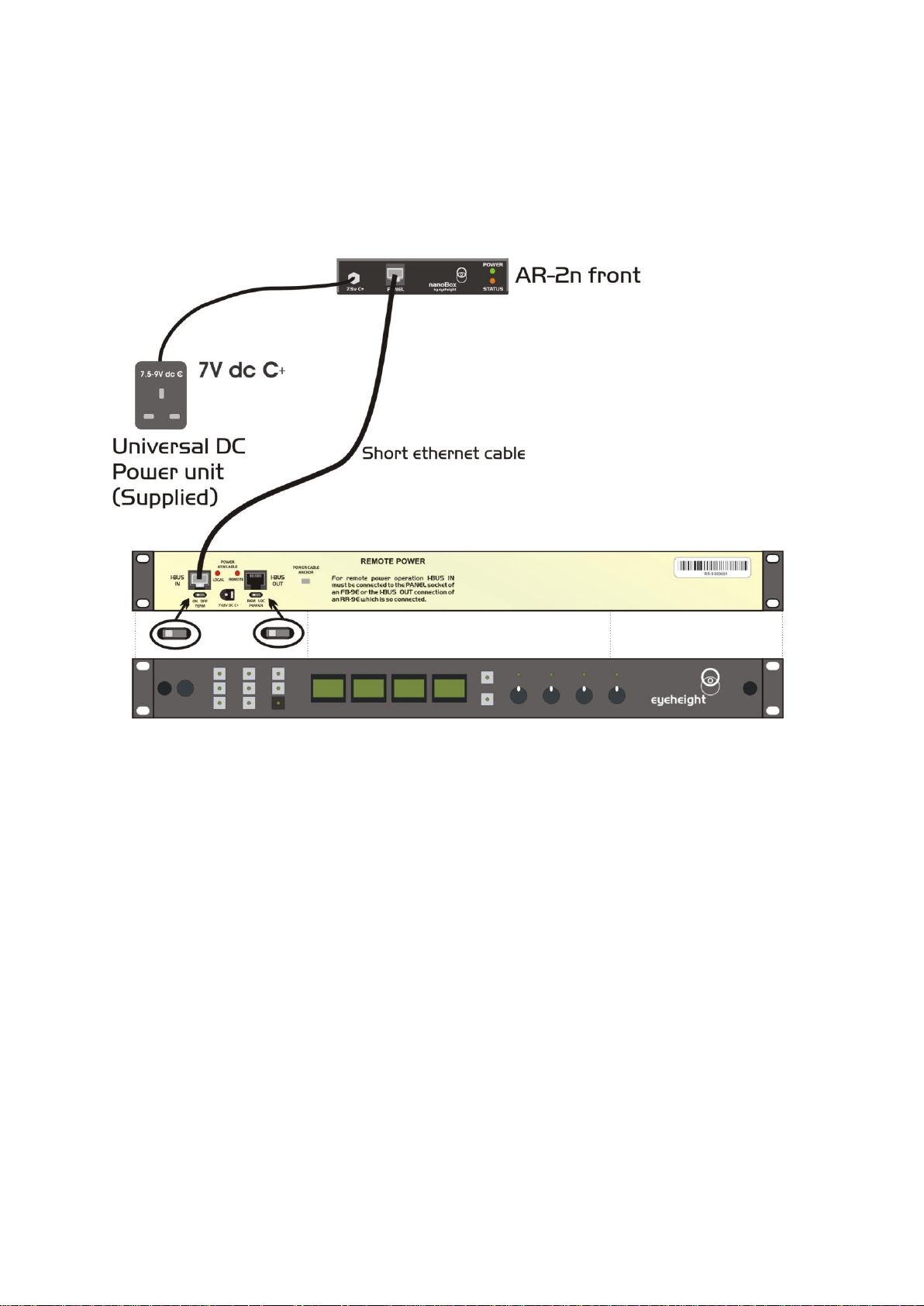
2.5 Connecting the AR-2n using an FP-9.
The AR-2n is normally shipped for operation with a soft panel. If you have
specifically asked for the system to operate with a flexipanel then it will be
shipped this way. The control and power connections are shown in the diagram
- 13 -
Page 14
Eyeheight Limited, Sutton Business Centre, Restmor Way, Wallington, Surrey SM6 7AH
Reg. No. 2855535 Telephone: +44 (0) 208 255 2015 Fax: +44 (0) 208 241 6951 email: [email protected]
below. After power up the Status light should turn from red to orange indicating
that it is operational in FP-9 panel mode. If the status light goes green then the
system was factory configured for operation with a soft panel. In the unlikely
event that the status light stays red then the system has found an error and it will
need returning to the factory.
2-2 LE-2n Power and control connection using an FP-9.
The Ethernet cable must be <2M long or you may experience fading of the FP-9
display due to voltage drop from the power supply in the LE-2n. If you wish to
mount the FP-9 panel very remotely (up to 150 Metres) then set the power switch
on the RR-9 (Rear box for the FP-9) to “LOC” (Local) and use the power supply
supplied with the RR-9 to power the panel.
- 14 -
Page 15
Eyeheight Limited, Sutton Business Centre, Restmor Way, Wallington, Surrey SM6 7AH
Reg. No. 2855535 Telephone: +44 (0) 208 255 2015 Fax: +44 (0) 208 241 6951 email: [email protected]
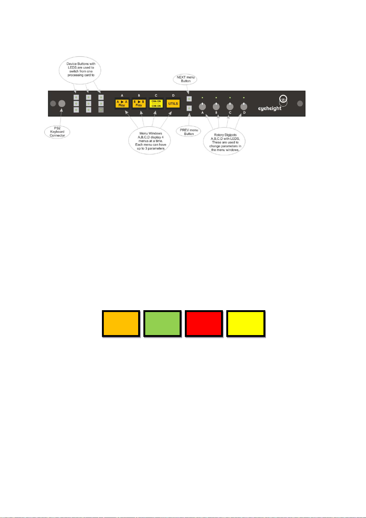
2.5.1 Flexipanel controls.
GOTO
ANOTHER
MENU
SINGLE
PARAMETER
ADJUSTMENT
DOUBLE OR
TRIPLE
PARAMETER
ADJUSTMENT
INFORMATION
DISPLAY
Figure 2-4 Types of menus showing their characteristic colours
Figure 2-3 Flexipanel (FP-9) controls.
2.5.2 Device Buttons.
There are 8 grey device buttons. These switch between the currently selected
processing cards installed in the etherbox. It is also possible to select cards in
another chassis if the I-Bus is connected to the other chassis.
2.5.3 Menu Navigation.
There are two ways to navigate from menu to menu.
1. Using the NEXT and PREV buttons. These are for “Flat” menu structures.
The NEXT and PREV LEDS will flash while further menus are available.
2. Using a GOTO ANOTHER MENU LCD button (as below coloured orange).
This is more common and will take you straight to a relevant set of menus.
Examples are the Play and UTILS menu‟s shown on Figure 8.
2.5.4 Parameter adjustment of a green menu.
A green menu is one in which there is only one adjustable parameter. There are
two ways to adjust the parameter in a green menu.
1. Press the green LCD button. This will increment the value in that window.
This is most frequently done when the menu parameter is Textural for
example switching a parameter between ON and OFF. In this case a
button press is most natural.
2. Use the Rotary digipot (A,B,C or D) to adjust the parameter in the
respective LCD window (A,B,C or D). The direction and speed of rotation
enable numeric values to be set easily.
- 15 -
Page 16

Eyeheight Limited, Sutton Business Centre, Restmor Way, Wallington, Surrey SM6 7AH
Reg. No. 2855535 Telephone: +44 (0) 208 255 2015 Fax: +44 (0) 208 241 6951 email: [email protected]
2.5.5 Parameter adjustment of a red menu
A red menu is one in which there is two or three adjustable parameters. In this
case it is necessary to first select the menu by pressing the red button. When the
red button is pressed it will turn green and either two or three of the rotary digipot
LEDS will flash indicating that the respective rotary digipot will operate the
respective parameter.
2.5.6 Information display
A Yellow menu (Which on most panels does look a light orange!) is one in which
only information is displayed. An example of this is the software version display.
- 16 -
Page 17
Eyeheight Limited, Sutton Business Centre, Restmor Way, Wallington, Surrey SM6 7AH
Reg. No. 2855535 Telephone: +44 (0) 208 255 2015 Fax: +44 (0) 208 241 6951 email: [email protected]
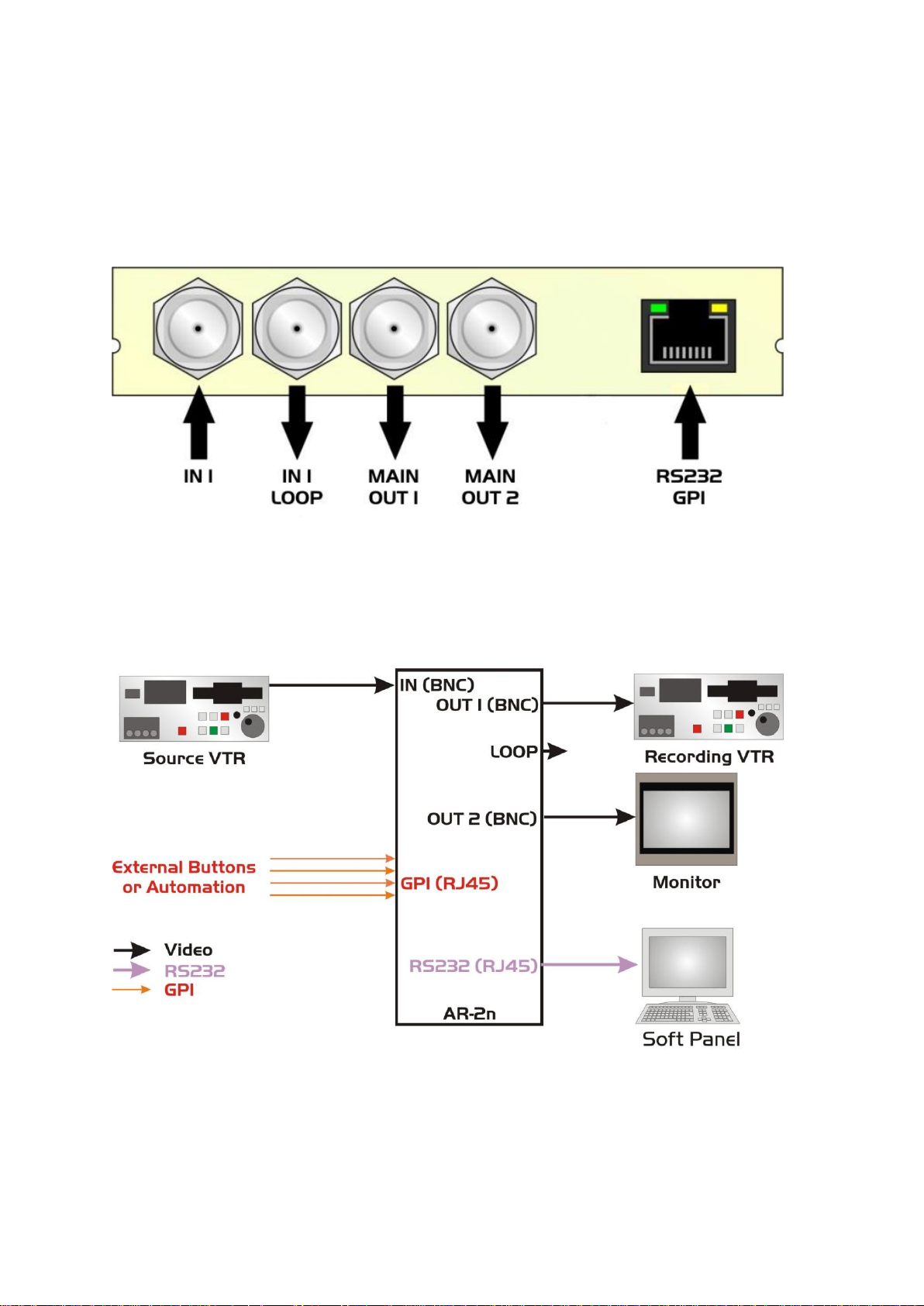
3 Connecting Video to the AR-2n
This unit requires HD-SDI or SDI digital video connections to the BNC
connectors.
Figure 3-1 - Video connections to the AR-2N
The main video connections to the AR-2n are shown above. The Main Out 1 and
Main Out 2 are the main ARC outputs. They are functionally identical to each
other. The In 1 Loop is a “reclocked input” loop output. Four GPI‟s can be used to
recall user memories.
Figure 3-2 AR-2n Connections.
- 17 -
Page 18
Eyeheight Limited, Sutton Business Centre, Restmor Way, Wallington, Surrey SM6 7AH
Reg. No. 2855535 Telephone: +44 (0) 208 255 2015 Fax: +44 (0) 208 241 6951 email: [email protected]
4 Other Features/Messaging
The messaging system is used to access some features within the unit. This is
done differently if you are using the soft panel than if you are using a “hard” FP-9
Panel.
4.1 Messaging with the soft java panel.
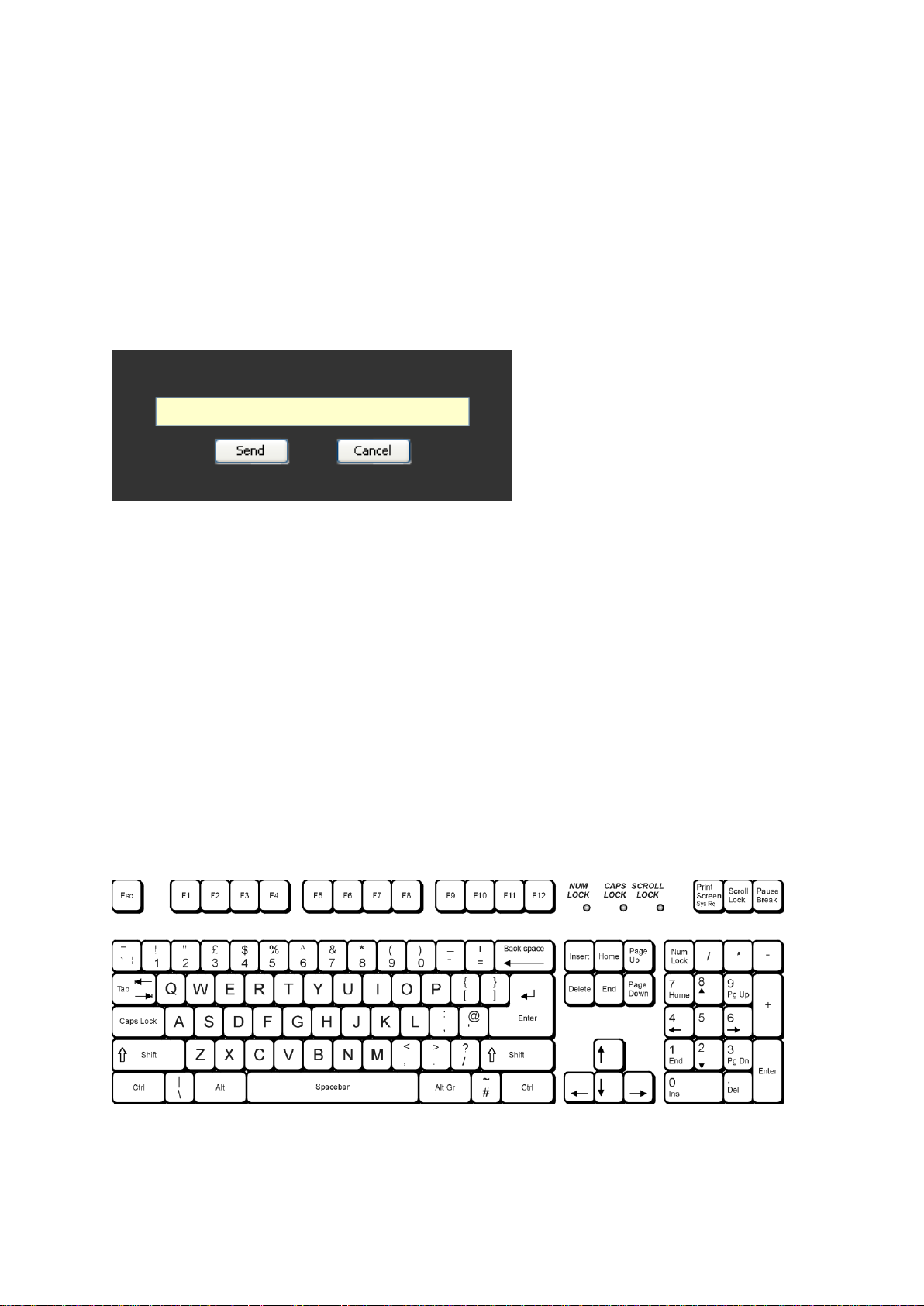
Use [Tools > Send Message] to see the message screen as below:
The text box will accept a message up to 32 characters in length.
Click the Send button to send the message. The Status Bar will display a
confirmation or error message to acknowledge success or failure.
Click the Cancel button to return to the normal menu window.
4.2 Messaging with an FP-9.
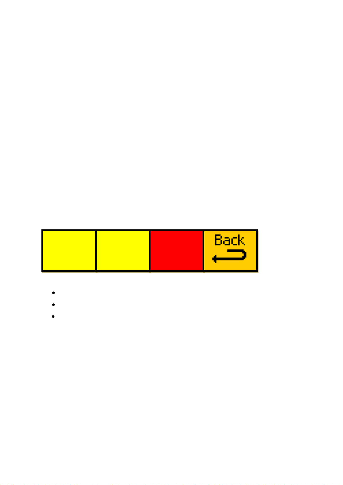
Plug in a PS-2 Keyboard into a Flexipanel and select the appropriate processor
card with a device button. (See Error! Reference source not found. for
connector location). Hit F9 function key. The LCD displays will change to text
entry mode. Now type in the text and press return to send their message. Please
be aware that the FP-9 only maps to a UK keyboard. Other keyboards may be
used but the location of the keys must be referenced to the diagram below.
Figure 4-1 UK keyboard reference diagram.
- 18 -
Page 19
Eyeheight Limited, Sutton Business Centre, Restmor Way, Wallington, Surrey SM6 7AH
Reg. No. 2855535 Telephone: +44 (0) 208 255 2015 Fax: +44 (0) 208 241 6951 email: [email protected]
4.3 Tamper Locking the AR-2n.
Defini
Frame
Frame
tion->
form->
rate->
625
I
50
The user can lock specific menus or all the menus on the AR-2n so that it cannot
be adjusted with a manual control panel. This does not effect automation.
To lock only menu 52. (General Noise Reduction (GNR)):
1. Use the appropriate messaging system to send “L52:” (do not include the
quotes)
A padlock symbol will appear on the menu and it cannot be adjusted. To unlock
menu 52, type “A52:”. Other menus are done in the same way
To lock the whole product type “L:” and to unlock the whole product type “A:” .
4.4 Primary AR-2N control
4.4.1 Setting the output video standard
Setting the output video standard is done via the below menu, which is found
under “Utils Video Output”
When menu window 3 is selected:
Digipot A will change the output video definition
Digipot B will toggle between Progressive and Interlaced output
Digipot C will select the output video frame rate
It is advisable to make changes to this menu slowly, as the display can lag
slightly depending on the current fade transition settings.
All changes to this menu are saved as they are made, so if the unit loses power
for any reason it will keep the same video standard it had before it lost power.
A complete list of available output standards is listed in the technical specification
found in section 6.2.
4.4.2 Bypass mode operation
The top level menu shown below gives a basic overview of the current state of
the unit, as well as containing the Bypass Mode control.
- 19 -
Page 20
Eyeheight Limited, Sutton Business Centre, Restmor Way, Wallington, Surrey SM6 7AH
Reg. No. 2855535 Telephone: +44 (0) 208 255 2015 Fax: +44 (0) 208 241 6951 email: [email protected]
ARC
in
Bypass
Video
Input
=625
ARC
off
Video
Input
=625
Pressing the “Bypass” button will toggle the state of bypass mode between off
and on. By default the unit will boot up with bypass mode off.
Turning Bypass mode on will display something similar to the display below:
The loaded memory display changes to state the ARC is in bypass mode, and
that the previously loaded memory is not being used. When in Bypass mode:
The output picture size and position are changed to the default values for
the current output video standard.
All picture blanking is turned off.
The audio delay is set to the default for the current input standard.
All menus that have had values changed in this process are locked to
prevent them being changed.
Loading a memory is also locked.
When Bypass mode is subsequently turned off, the previous settings for the
above are re-loaded automatically.
Note that Bypass mode cannot be enabled if no valid input video is present.
All changes to this menu are saved as they are made, so if the unit loses power
for any reason it will keep the same video standard it had before it lost power.
4.4.3 Loading a memory
There are two types of memory: The 11 preset memories and the 53 user
memories. There are several things to bear in mind when loading a memory:
When loading a preset memory, only the output picture aspect ratio is
changed. All other settings (input picture blanking, etc.) are left at their
previous values.
Only user memories saved in the same input standard as the unit currently
detects can be loaded. For example, a memory saved with an input
standard of 625 cannot be loaded if the current input standard is 525, 720
or 1080.
- 20 -
Page 21
Eyeheight Limited, Sutton Business Centre, Restmor Way, Wallington, Surrey SM6 7AH
Reg. No. 2855535 Telephone: +44 (0) 208 255 2015 Fax: +44 (0) 208 241 6951 email: [email protected]
When loading a user memory, if the stored output video standard differs
16F16
to
16L12
16F16
to
14L12
16F16
to
12F12
next
*BACK*
----->
ACTIVE
----->
ARC
off
from the current video standard, the output will change to that which is
stored in the user memory. This will cause temporary disruption to the
output video stream while the new standard is being loaded.
The load memory top-level menu is the one shown below, which is found under
“On Air”
Menu window B shows the currently loaded memory; in this case memory #11
“ARC off” is loaded.
To load a different menu, pressing the “Select” button will show the first in a
series of menus that show the memories:
Use the next and prev buttons on the panel to navigate to other memories. A
memory that is not valid for the current input video standard will be locked.
The preset memories, in order, are:
1. 16F16 to 16L12
2. 16F16 to 14L12
3. 16F16 to 12F12
4. 12F12 to 12P16
5. 12F12 to 14P16
6. 12F12 to 16F16
7. 12P16 to 16F16
8. 12P16 to 14P16
9. 14P16 to 16F16
10. Auto ARC mode
11. ARC off
To load memories 1 to 23, simply press the icon for that memory. The panel
display will switch to the display shown below, and will return to the load memory
top-level menu after a brief pause.
- 21 -
Page 22
Eyeheight Limited, Sutton Business Centre, Restmor Way, Wallington, Surrey SM6 7AH
Reg. No. 2855535 Telephone: +44 (0) 208 255 2015 Fax: +44 (0) 208 241 6951 email: [email protected]
#4=OFF
LH=0
HL=0
GPO #1
=OFF
*BACK*
prev
#1=OFF
LH=0
HL=0
#2=OFF
LH=0
HL=0
#3=OFF
LH=0
HL=0
next
*BACK*
Select
Memory
----->
User
define
mem13
-----APPLY
------
******
PLEASE
WAIT
******
Memories 24-64 are accessed via the menu below:
The memory to load is displayed in menu window B. To cycle through the other
memories, either press menu window B or use the digipot for that menu.
When the memory you want to load is selected in menu window B, pressing the
“APPLY” button will put the selected menu on air, with the same procedure
afterwards as described above.
Note that if a memory is not valid, the “apply” button will be locked.
4.4.4 Setting up the GPIs
The GPIs on the AR-2N are used solely to load memories.
Setting the GPIs uses the following menus, which are found under “Utils
Global Setup GPI/O”
There are a few of things to note:
LH stands for the „Low to High‟ transition, and HL stands for the „High to
Low‟ transition.
If an LH or HL value is 0, then no change to the current memory will
happen for that transition type
If LH = HL, then that memory value will be loaded on any change in state
of that GPI
- 22 -
Page 23
Eyeheight Limited, Sutton Business Centre, Restmor Way, Wallington, Surrey SM6 7AH
Reg. No. 2855535 Telephone: +44 (0) 208 255 2015 Fax: +44 (0) 208 241 6951 email: [email protected]
Even if the current memory loaded is the same as the one asked for by a
Triggr
=OFF
RCL if
val=0
mem=1
16F16
to
16L12
change in GPI state, the memory will be re-loaded, which may result in a
brief disruption in output video.
It is possible using GPIs to load user memories that were saved with an
input standard that differs from the current input standard, which may give
undesired results. Memories 1 to 11 are presets, and memories 12 to 64
are the user presets.
All changes to this menu are saved automatically, and will not be lost if the unit
loses power for any reason.
Wiring diagrams for the GPIs and the GPO (tally) can be found in section 6.1.
4.4.5 Setting up embedded video signalling parameters
The AR-2N can be set up to load different user memories automatically upon
detection of embedded video switching signals. The menu used to set this
feature up is shown below, which is found under “Utils Global Setup
Sgnllng”
There are 4 different modes:
VI (AFD or AR)
WSS (UK or ETSI)
The 8 different values of each mode are set up using menu window B in the
following way:
Digipot A sets the value of the mode which you want to set a memory for
Digipot B assigns a memory to be loaded when the value of the mode
selected is the same as that specified by digipot A.
By default, Trigger is „off‟ and the memories to be recalled all point to
memory #11 (ARC off).
All changes to this menu are saved as soon as they are made, and will not be
lost if the unit loses power for any reason.
4.4.6 Setting up the transition parameters
This menu sets how the transition between memories will look. It is found under
“Utils Global Setup Fading”
- 23 -
Page 24
Eyeheight Limited, Sutton Business Centre, Restmor Way, Wallington, Surrey SM6 7AH
Reg. No. 2855535 Telephone: +44 (0) 208 255 2015 Fax: +44 (0) 208 241 6951 email: [email protected]
X-fade
Time
=1 fr
Black
Fade
= off
FD=1
HD=1
FU=1
If black fade is off, the cross-fading setting is used.
If black fade is on, the settings specified in menu window C will be used
The settings for the black fade are as follows:
Digipot A adjusts the Fade Down time
Digipot B adjusts the faded-down Hold Delay
Digipot C adjusts the Fade Up time
All delay times are expressed in the number of frames. This means the fastest
transition possible is using cross-fading, which can be done in 1 frame. Black
fade transitions take a minimum of 3 frames to complete.
All changes to this menu are saved as they are made, and will not be lost if the
unit loses power for any reason.
4.4.7 Setting the power-on default values
The AR-2N constantly stores any changes made to all settings under the „global
setup‟ menu, so if the unit loses power these settings will automatically be
restored. These values are:
GPI/O
Signalling
Transition fade settings
The Auto-ARC mode setting
In addition to the above, the following are also constantly updated:
Output Video Mode
The currently loaded memory
The state of Bypass Mode
4.5 Advanced AR-2N control
4.5.1 Adjusting the output picture dimensions
Adjustment of the output picture parameters uses the menu below, found under
“Utils ARC”
- 24 -
Page 25
Eyeheight Limited, Sutton Business Centre, Restmor Way, Wallington, Surrey SM6 7AH
Reg. No. 2855535 Telephone: +44 (0) 208 255 2015 Fax: +44 (0) 208 241 6951 email: [email protected]
Audio
delay
=2 fi
Blnkng
T=0
B=0
Blnkng
L=0
R=0
Size
H=720
V=576
Positn
H+0
V+0
The output picture is defined by the number of horizontal and vertical pixels, and
the position offset is also defined in pixels. All adjustments take effect as soon as
they are made.
The limits to the amount of adjustment available vary depending on the input and
output video standards, but the maximum dimensions possible are 4000 x 2250.
Any output picture can be reduced to a single pixel output.
4.5.2 Adjusting the input picture blanking
Adjustment of the input picture blanking parameters uses the menu below, found
under “Utils Blank”
The blanking is defined as the number of pixels in from the edge of the input
video picture that you want to be blanked off.
T is the number of pixels of blanking from the top of the picture
B is the number of pixels from the bottom of the picture
L is the number of pixels from the left edge of the picture
R is the number of pixels from the right edge of the picture
By default, all blanking variables are set to zero.
4.5.3 Setting the Audio delay
The audio delay can be customised from this menu, found under “Utils Audio”
By default, the audio delay is set to match the processing delay of the video
input, which is either 1 or 2 fields depending on the video standards being used.
Use digipot A to adjust the audio delay to the value you require. The maximum
delay allowed is 16 fields.
- 25 -
Page 26
Eyeheight Limited, Sutton Business Centre, Restmor Way, Wallington, Surrey SM6 7AH
Reg. No. 2855535 Telephone: +44 (0) 208 255 2015 Fax: +44 (0) 208 241 6951 email: [email protected]
Txture
H=0
V=0
Txture
D=0
OC=0
Txture
enable
= OFF
Sharp
H=0
V=0
Sharp
D=0
OC=0
Sharp
enable
= OFF
GNR
= 0
BAR
= 0
MNR
= 0
4.5.4 Adjusting the advanced video options
The advanced video options allow you to compensate for various imperfections
that may be present in the picture.
4.5.4.1 Noise Reduction
The Noise Reduction feature is accessed through the menu shown below, found
under “Utils Video Advncd Ns.Rdct”
Menu window A adjusts the General noise reduction, which comprises of both
adaptive 2D and 3D noise reduction. The 3D noise reduction corrects for
temporal and spatial noise on input signals with a pixel rate of less than 75Mp/s,
whereas the 2D noise reduction corrects for spatial noise only on all input signals.
The AR-2N automatically selects the applicable correction for the current input
signal, using the level set by the user.
Menu window B adjusts the Block Artefact Reduction level. This reduces the
block edges produced by DCT-based compression processing. BAR can be
applied to any interlaced or progressive input signal.
Menu window C adjusts the Mosquito Noise Reduction level, which dynamically
adapts to image content, effectively reducing mosquito artefacts around sharp
edges in DCT-based compression. MNR can be applied to any interlaced or
progressive input signal.
All of these values have a range 0-63, where 0 is off and 63 is maximum effect.
4.5.4.2 Edge Sharpening and Texture Enhancement
The Edge Sharpening and Texture Enhancement features are accessed through
the menus shown below, found under “Utils Video Advncd Shrpns” and
“Utils Video Advncd Txture” respectively.
- 26 -
Page 27
Eyeheight Limited, Sutton Business Centre, Restmor Way, Wallington, Surrey SM6 7AH
Reg. No. 2855535 Telephone: +44 (0) 208 255 2015 Fax: +44 (0) 208 241 6951 email: [email protected]
The sharpness settings affect „large edges‟, whilst the texture settings affect
AAM=
No Img
Crop
Clear
All
Vars
Sh+Txt
Y only
= OFF
Sh+Txt
NA Lim
= 0
„small edges‟.
The H parameter adjusts the Horizontal sharpness/texture, range 0-63.
The V parameter adjusts the Vertical sharpness/texture, range 0-63.
The D parameter adjusts the Diagonal sharpness/texture, range 0-63.
The OC parameter adjusts the Overshoot Control for the
sharpness/texture, which is used to minimise ringing on the enhanced
edges. The range for this variable is 0-255.
The enable setting turns on and off the applicable type of enhancement.
There are also a couple more settings that effect the sharpness and texture
adjustment, which are accessed via the menu shown below, found under “Utils
Video Advncd Misc.”
Menu window A sets the target of the sharpness and texture enhancement. If
this is set to on, edge sharpening and texture enhancement is applied to the Y
(Luma) channel only. If set to off, edge sharpening and texture enhancement is
applied to RGB channels independently.
Menu window B sets the Noise Adaption threshold value. This setting will limit
the effect of the edge sharpening and texture enhancement settings in areas of
video that are noisy, to prevent enhancing noise. The range is 0 (no noise
adaption) to 63 (maximum limiting of enhancement effects in noisy picture areas).
4.5.5 Auto-ARC mode and the Clear all vars function
Settings for these are found in the menu shown below, under “Utils Global
Setup Misc.”
Menu window A sets the action taken for the Auto ARC mode function, which is
only used if the active memory is memory #10 (Auto ARC mode) and is only of
use for the AR-2 MD, and only then if the unit is being used to up/down scale.
For any fixed input, Auto ARC mode will automatically adjust the aspect ratio if
the selected output standard is different from the input.
For SD in HD out:
- 27 -
Page 28

Eyeheight Limited, Sutton Business Centre, Restmor Way, Wallington, Surrey SM6 7AH
Reg. No. 2855535 Telephone: +44 (0) 208 255 2015 Fax: +44 (0) 208 241 6951 email: [email protected]
No Img Crop will perform a 12F12 to 12P16 conversion
Compromise will perform a 12F12 to 14P16 conversion
Full Screen will perform a 12F12 to 16P16 conversion
For HD in SD out:
No Img Crop will perform a 16F16 to 16L12 conversion
Compromise will perform a 16F16 to 14L12 conversion
Full Screen will perform a 16F16 to 12F12 conversion
Menu window B is used to clear a number of the user customisable settings of
the AR-2N in one go.
Pressing the button will set the following:
Input Picture Blanking to zero
All Noise Reduction values to zero
Edge Sharpening disabled and all sharpness settings to zero
Texture Enhancement disabled and all texture settings to zero
Sh+Txt Y ch only to off and the NA threshold value to zero
Audio delay to the default for the current input video standard
The menu will briefly display the message „all vars cleared‟ when the operation is
completed successfully (this is usually almost instant).
4.5.6 Saving a user memory
The following settings are stored when creating a user memory:
Output picture aspect ratio
Input picture blanking
Input video standard
Output video standard
Noise reduction
Edge sharpening
Texture enhancement
Audio delay
Film mode setting
Saving a user memory starts with the menu below, found under “Softw‟r Mems
Save”
- 28 -
Page 29
Eyeheight Limited, Sutton Business Centre, Restmor Way, Wallington, Surrey SM6 7AH
Reg. No. 2855535 Telephone: +44 (0) 208 255 2015 Fax: +44 (0) 208 241 6951 email: [email protected]
Edit->
Pos 1
val 53
User
define
mem01
!Save!
!!To!!
!Mem!!
Save
to:
mem 1
User
define
mem01
Select the memory which you wish to save to by pressing menu window A, or by
using the appropriate digipot. The current name of the memory selected is
displayed in menu window B.
When you have selected the location of the memory you wish to save to,
pressing “Save” will take you to the name editing screen shown below. From
there, you can save the memory with the current name or change the name to
something else.
To save the memory without changing the name, simply press menu window C.
After a brief pause, the display will change to “Saved!” to indicate the operation is
complete.
All 18 characters of a memory name can be changed. To change the name of
the memory, you will need to use the controls in menu window A.
Digipot A will change the position to be saved, from position 1 (top-left) to
position 18 (bottom-right). Position 7 is the beginning of the middle line.
The currently selected position will show an inverted cursor to make it
more obvious which value you are editing.
Digipot B changes the character at the selected position. The order of the
values is given below:
o values 1 – 26 are “A” to “Z” (upper-case)
o values 27 – 52 are “a” to “z” (lower-case)
o value 53 is space (and is also the value if you press the digipot)
o values 54 – 63 are numbers 0 to 9
o values 64 – 89 are various punctuation marks and symbols
When you‟ve finished changing the name, you save the memory in the same way
as described above.
- 29 -
Page 30
Eyeheight Limited, Sutton Business Centre, Restmor Way, Wallington, Surrey SM6 7AH
Reg. No. 2855535 Telephone: +44 (0) 208 255 2015 Fax: +44 (0) 208 241 6951 email: [email protected]
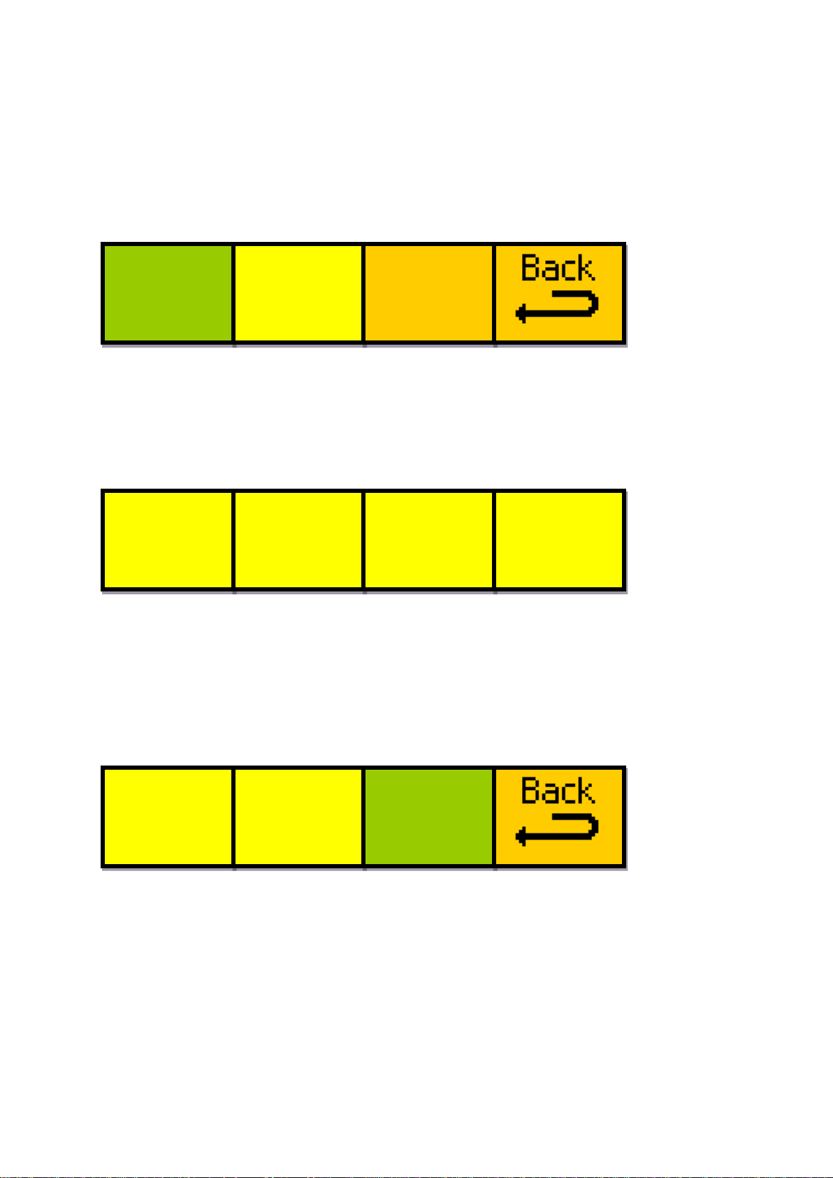
4.5.7 Viewing a saved memory
Move
mem to
On air
input
video
info
625
I
50
o/p
video
info
625
I
50
View
memory
no. 1
User
define
mem01
----- view
------
If you want to view the contents of a saved memory without putting it on-air, you
can use the „view memory‟ function to check the saved data contained within any
of the user memories.
Viewing a user memory starts from the following menu, found under “Softw‟r
Mems View”
Use digipot A to select the memory you want to view, in the range 1 to 53. The
preset memories cannot be viewed. The name of the memory selected is shown
in menu window B.
When you have selected the memory you want, pressing “view” (menu window
C) will take you to the view memory nested menu set; the first of which will look
similar to that shown below:
If the output video info displays “No Video Output”, the user memory being
viewed has not been saved to, and contains invalid data (the input video info will
display the same message).
To navigate through the saved data display, you will need to use the next and
prev buttons on the panel to cycle through the 6 nested menus, which all display
data saved within the selected memory.
The final menu of the 6 is shown below:
The fist two windows are intentionally blank.
Pressing “Move mem to On air” (menu window C), will set the memory you are
currently viewing as your active ARC memory. Once pressed, the “Please wait”
message will be displayed, and you will be returned to the On Air select menu
(shown below) rather than the view memory menu. It will show that the memory
you were viewing is now the active memory.
- 30 -
Page 31
Eyeheight Limited, Sutton Business Centre, Restmor Way, Wallington, Surrey SM6 7AH
Reg. No. 2855535 Telephone: +44 (0) 208 255 2015 Fax: +44 (0) 208 241 6951 email: [email protected]
AR-2
FILE
TIMES
IS UPG
IS REC
OUT IN
RADING
EIVED
3 MINS
IF NO
IT
AR-2
010108
v1.00
VIPER
010108
v1.00
Upgrde
Softwr
Now!!!
START?
Softwr
ARE
YOU
SURE?
----- YES
------
----->
ACTIVE
----->
User
define
mem01
Pressing “Back” will take you back to the view memory select menu without
changing the active memory.
Note that it is possible to load memories that are not guaranteed to be valid for
the current input video standard using the „move mem to on air‟ function. Caution
is advised when using this method to load a memory.
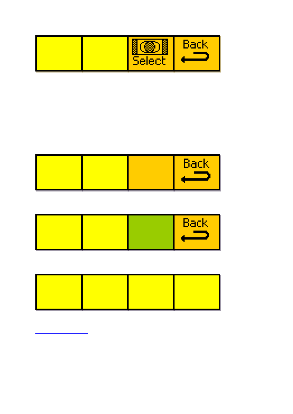
4.6 The software upgrade process
Navigate to the following menu, under “Softw‟r Ver‟ns”
Pressing “UPGRDE SOFTWR NOW!!!” will display the following set of menus
Pressing “YES” will display the following set of menus
The unit will be set into the state where it can be field upgraded using the
“Flasher” software which can be downloaded from our web site:
www.eyeheight.com
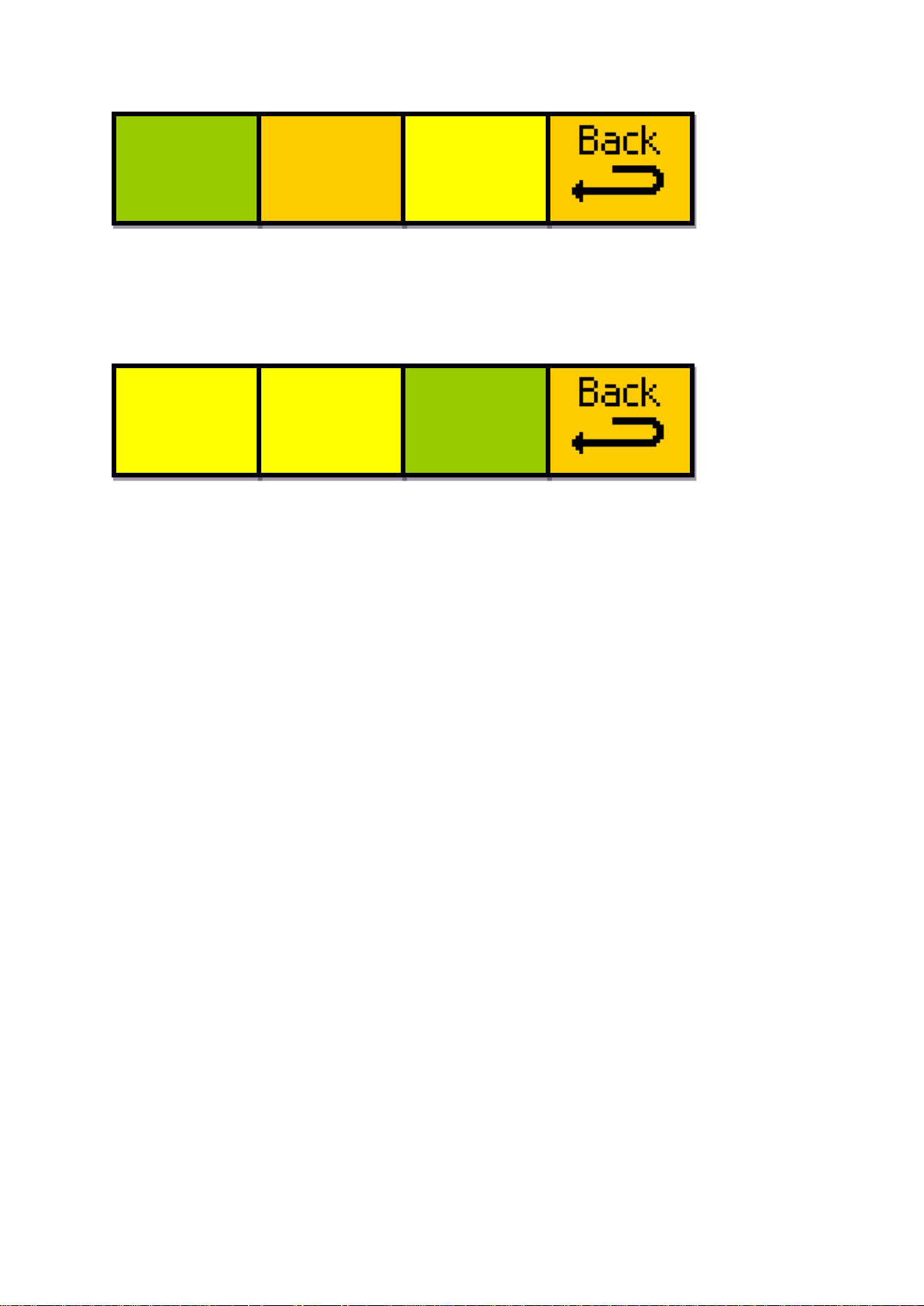
4.7 Unit reset options
Navigate to the following menu, under “Softw‟r Resets”
- 31 -
Page 32
Eyeheight Limited, Sutton Business Centre, Restmor Way, Wallington, Surrey SM6 7AH
Reg. No. 2855535 Telephone: +44 (0) 208 255 2015 Fax: +44 (0) 208 241 6951 email: [email protected]
Reboot
this
unit
Factry
reset
START?
Factry
ARE
YOU
SURE?
----- YES
------
The “Reboot this unit” option will restart the AR-2N as if the product had been
unplugged from the chassis. It is usual for the product not to respond for up to a
minute while settings are loaded.
Pressing “FACTRY RESET” will display the following set of menus
Pressing “YES” will restore all the factory default settings and will clear all the
memories.
WARNING! Performing a factory reset will permanently erase all user memories
that have been stored, as well as erasing the current power-on default setting.
- 32 -
Page 33
Eyeheight Limited, Sutton Business Centre, Restmor Way, Wallington, Surrey SM6 7AH
Reg. No. 2855535 Telephone: +44 (0) 208 255 2015 Fax: +44 (0) 208 241 6951 email: [email protected]
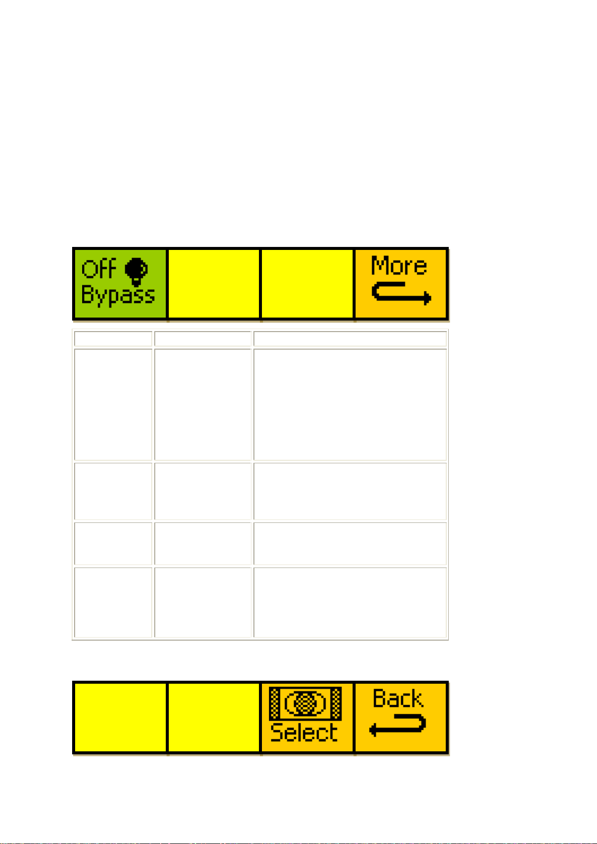
5 The AR-2N Menu Set
Menu Num.
Heading
Function
0
Bypass mode
This menu toggles bypass mode
between:
0 = OFF
1 = ON
See section 4.4.2 for an in-depth
explanation of this function
1
Active ARC
memory
This is a display for the currently
loaded memory being used by
the AR-2N.
2
Video Input
This is a display for the current
input video standard.
3
More
Pressing this menu button will
display the on air select, utilities
and software menus (Go To
Menus 128-131).
----->
ACTIVE
----->
ARC
off
ARC
off
Video
Input
=625
The following set of menus defines the operational controls of the AR-2N.
Note: Only parameters with RED menu numbers are stored in the memories, and
only parameters in BLUE are saved automatically as soon as they are changed.
Values in bold in the Heading section are the factory set default values, which
will be restored if a factory reset is ever performed.
Menus 00-03 Main Menu Set 1/2
Menus 04-07 ARC Memory Select Top Menus
- 33 -
Page 34
Eyeheight Limited, Sutton Business Centre, Restmor Way, Wallington, Surrey SM6 7AH
Reg. No. 2855535 Telephone: +44 (0) 208 255 2015 Fax: +44 (0) 208 241 6951 email: [email protected]
Menu Num.
Heading
Function
4
---
---
5
Active ARC
This is a display for the currently
loaded memory being used by
the AR-2N.
6
Select
This button takes you to the first
of the nested memory loading
menus (Go To Menus 08-11).
7
Back
Pressing this menu button will
display the top level menus (Go
To Menus 128-131).
Menu Num.
Heading
Function
8
Load memory
„16F16 to 16L12‟
Pressing this button will load
memory 1 of 64, which is a
preset memory which cannot be
overwritten.
This will change the panel
display to „please wait‟, and will
return after a short delay to the
ARC Memory Select Top
Menus (Go To Menus 04-07)
9
Load memory
„16F16 to 14L12‟
Pressing this button will load
memory 2 of 64, which is a
preset memory which cannot be
overwritten.
This will change the panel
display to „please wait‟, and will
return after a short delay to the
ARC Memory Select Top
Menus (Go To Menus 04-07)
16F16
to
16L12
16F16
to
14L12
16F16
to
12F12
next
*BACK*
Menus 08-11 Change Active Memory 1/8
- 34 -
Page 35
Eyeheight Limited, Sutton Business Centre, Restmor Way, Wallington, Surrey SM6 7AH
Reg. No. 2855535 Telephone: +44 (0) 208 255 2015 Fax: +44 (0) 208 241 6951 email: [email protected]
10
Load memory
„16F16 to 12F12‟
Pressing this button will load
memory 3 of 64, which is a
preset memory which cannot be
overwritten.
This will change the panel
display to „please wait‟, and will
return after a short delay to the
ARC Memory Select Top
Menus (Go To Menus 04-07)
11
Back
Pressing this button takes you
to the previous level of menus
(Go To Menus 04-07)
Pressing the next button on the
panel will take you to the next
menu in the nested menu
sequence (Go To Menus 12-
15)
Menu Num.
Heading
Function
12
Load memory
„12F12 to 12P16‟
Pressing this button will load
memory 4 of 64, which is a
preset memory which cannot be
overwritten.
This will change the panel
display to „please wait‟, and will
return after a short delay to the
ARC Memory Select Top
Menus (Go To Menus 04-07)
13
Load memory
„12F12 to 14P16‟
Pressing this button will load
memory 5 of 64, which is a
preset memory which cannot be
overwritten.
This will change the panel
display to „please wait‟, and will
12F12
to
12P16
12F12
to
14P16
12F12
to
16F16
next
*BACK*
prev
Menus 12-15 Change Active Memory 2/8
- 35 -
Page 36
Eyeheight Limited, Sutton Business Centre, Restmor Way, Wallington, Surrey SM6 7AH
Reg. No. 2855535 Telephone: +44 (0) 208 255 2015 Fax: +44 (0) 208 241 6951 email: [email protected]
return after a short delay to the
ARC Memory Select Top
Menus (Go To Menus 04-07)
14
Load memory
„12F12 to 16F16‟
Pressing this button will load
memory 6 of 64, which is a
preset memory which cannot be
overwritten.
This will change the panel
display to „please wait‟, and will
return after a short delay to the
ARC Memory Select Top
Menus (Go To Menus 04-07)
15
Back
Pressing this button takes you
to the previous level of menus
(Go To Menus 04-07)
Pressing the next button on the
panel will take you to the next
menu in the nested menu
sequence (Go To
Menus 16-19)
Pressing the prev button on the
panel will take you to the
previous menu in the nested
menu sequence (Go To Menus
08-11)
Menu Num.
Heading
Function
16
Load memory
„12P16 to 12F12‟
Pressing this button will load
memory 7 of 64, which is a
preset memory which cannot be
overwritten.
This will change the panel
display to „please wait‟, and will
12P16
to
12F16
12P16
to
14P16
14P16
to
16F16
next
*BACK*
prev
Menus 16-19 Change Active Memory 3/8
- 36 -
Page 37

Eyeheight Limited, Sutton Business Centre, Restmor Way, Wallington, Surrey SM6 7AH
Reg. No. 2855535 Telephone: +44 (0) 208 255 2015 Fax: +44 (0) 208 241 6951 email: [email protected]
return after a short delay to the
ARC Memory Select Top
Menus (Go To Menus 04-07)
17
Load memory
„12P16 to 14P16‟
Pressing this button will load
memory 8 of 64, which is a
preset memory which cannot be
overwritten.
This will change the panel
display to „please wait‟, and will
return after a short delay to the
ARC Memory Select Top
Menus (Go To Menus 04-07)
18
Load memory
„14P16 to 16F16‟
Pressing this button will load
memory 9 of 64, which is a
preset memory which cannot be
overwritten.
This will change the panel
display to „please wait‟, and will
return after a short delay to the
ARC Memory Select Top
Menus (Go To Menus 04-07)
19
Back
Pressing the button takes you
to the previous level of menus
(Go To Menus 04-07)
Pressing the next button on the
panel will take you to the next
menu in the nested menu
sequence (Go To
Menus 20-23)
Pressing the prev button on the
panel will take you to the
previous menu in the nested
menu sequence (Go To Menus
12-15)
Menus 20-23 Change Active Memory 4/8
- 37 -
Page 38

Eyeheight Limited, Sutton Business Centre, Restmor Way, Wallington, Surrey SM6 7AH
Reg. No. 2855535 Telephone: +44 (0) 208 255 2015 Fax: +44 (0) 208 241 6951 email: [email protected]
Menu Num.
Heading
Function
20
Load memory
„Auto ARC
mode‟
Pressing this button will load
memory 10 of 64, which is a
preset memory which cannot be
overwritten.
This will change the panel display
to „please wait‟, and will return
after a short delay to the ARC
Memory Select Top Menus (Go
To Menus 04-07)
21
Load memory
„ARC off‟
Pressing this button will load
memory 11 of 64, which is a
preset memory which cannot be
overwritten.
This will change the panel display
to „please wait‟, and will return
after a short delay to the ARC
Memory Select Top Menus (Go
To Menus 04-07)
22
Load memory
„User define
mem01‟
Pressing this button will load
memory 12 of 64.
This will change the panel display
to „please wait‟, and will return
after a short delay to the ARC
Memory Select Top Menus (Go
To Menus 04-07)
23
Back
Pressing the button takes you to
the previous level of menus (Go
To Menus 04-07)
Pressing the next button on the
panel will take you to the next
menu in the nested menu
sequence (Go To Menus 24-27)
Pressing the prev button on the
panel will take you to the previous
Auto
ARC
mode
Turn
ARC
off
User
define
mem01
next
*BACK*
prev
- 38 -
Page 39
Eyeheight Limited, Sutton Business Centre, Restmor Way, Wallington, Surrey SM6 7AH
Reg. No. 2855535 Telephone: +44 (0) 208 255 2015 Fax: +44 (0) 208 241 6951 email: [email protected]
menu in the nested menu
sequence (Go To
Menus 16-19)
Menu Num.
Heading
Function
24
Load memory
„User define
mem02‟
Pressing this button will load
memory 13 of 64.
This will change the panel display
to „please wait‟, and will return
after a short delay to the ARC
Memory Select Top Menus (Go
To Menus 04-07)
25
Load memory
„User define
mem03‟
Pressing this button will load
memory 14 of 64.
This will change the panel display
to „please wait‟, and will return
after a short delay to the ARC
Memory Select Top Menus (Go
To Menus 04-07)
26
Load memory
„User define
mem04‟
Pressing this button will load
memory 15 of 64.
This will change the panel display
to „please wait‟, and will return
after a short delay to the ARC
Memory Select Top Menus (Go
To Menus 04-07)
27
Back
Pressing the button takes you to
the previous level of menus (Go
To Menus 04-07)
Pressing the next button on the
panel will take you to the next
menu in the nested menu
User
define
mem02
User
define
mem03
User
define
mem04
next
*BACK*
prev
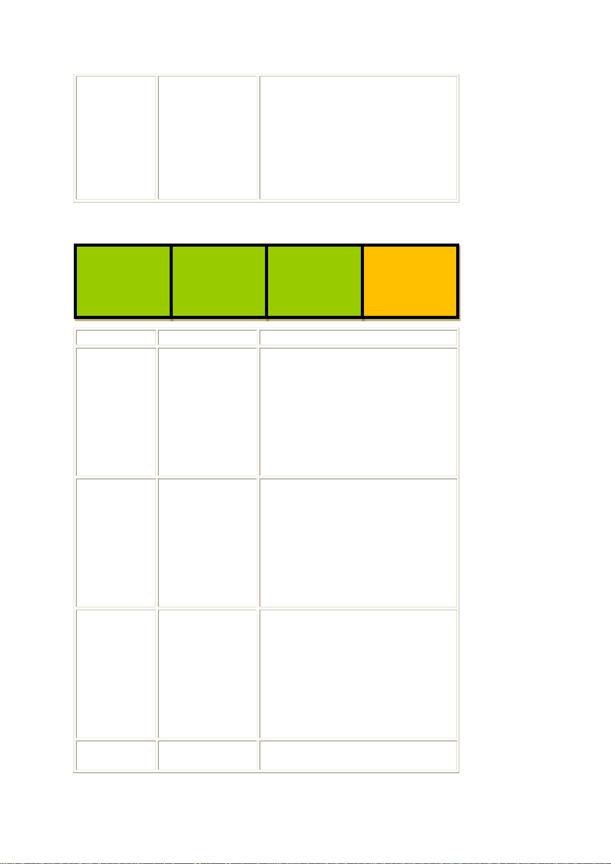
Menus 24-27 Change Active Memory 5/8
- 39 -
Page 40
Eyeheight Limited, Sutton Business Centre, Restmor Way, Wallington, Surrey SM6 7AH
Reg. No. 2855535 Telephone: +44 (0) 208 255 2015 Fax: +44 (0) 208 241 6951 email: [email protected]
sequence (Go To Menus 28-31)
Pressing the prev button on the
panel will take you to the previous
menu in the nested menu
sequence (Go To
Menus 20-23)
Menu Num.
Heading
Function
28
Load memory
„User define
mem05‟
Pressing this button will load
memory 16 of 64
This will change the panel display
to „please wait‟, and will return
after a short delay to the ARC
Memory Select Top Menus (Go
To Menus 04-07)
29
Load memory
„User define
mem06‟
Pressing this button will load
memory 17 of 64
This will change the panel display
to „please wait‟, and will return
after a short delay to the ARC
Memory Select Top Menus (Go
To Menus 04-07)
30
Load memory
„User define
mem07‟
Pressing this button will load
memory 18 of 64
This will change the panel display
to „please wait‟, and will return
after a short delay to the ARC
Memory Select Top Menus (Go
To Menus 04-07)
31
Back
Pressing the button takes you to
the previous level of menus (Go
User
define
mem05
User
define
mem06
User
define
mem07
next
*BACK*
prev
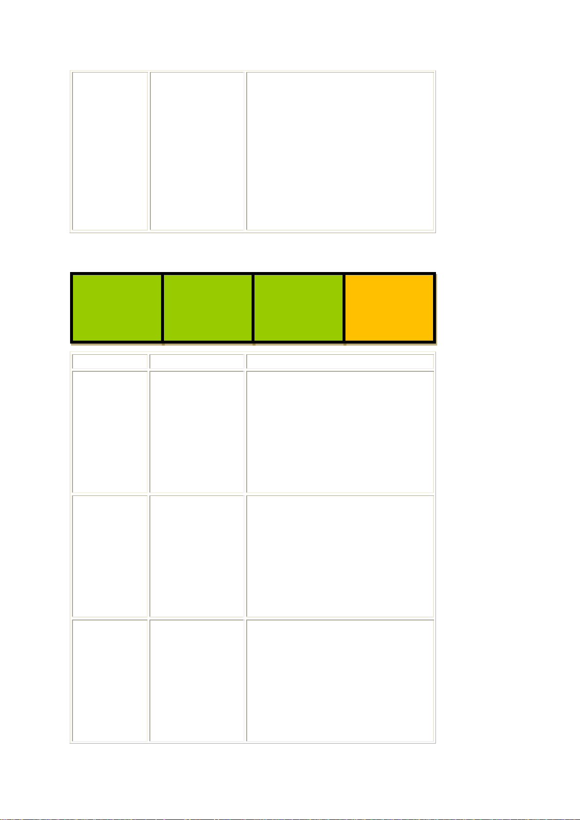
Menus 28-31 Change Active Memory 6/8
- 40 -
Page 41
Eyeheight Limited, Sutton Business Centre, Restmor Way, Wallington, Surrey SM6 7AH
Reg. No. 2855535 Telephone: +44 (0) 208 255 2015 Fax: +44 (0) 208 241 6951 email: [email protected]
To Menus 04-07)
Pressing the next button on the
panel will take you to the next
menu in the nested menu
sequence (Go To Menus 32-35)
Pressing the prev button on the
panel will take you to the previous
menu in the nested menu
sequence (Go To Menus 24-27)
Menu Num.
Heading
Function
32
Load memory
„User define
mem08‟
Pressing this button will load
memory 19 of 64
This will change the panel display
to „please wait‟, and will return
after a short delay to the ARC
Memory Select Top Menus (Go
To Menus 04-07)
33
Load memory
„User define
mem09‟
Pressing this button will load
memory 20 of 64
This will change the panel display
to „please wait‟, and will return
after a short delay to the ARC
Memory Select Top Menus (Go
To Menus 04-07)
34
Load memory
„User define
mem10‟
Pressing this button will load
memory 21 of 64
This will change the panel display
to „please wait‟, and will return
after a short delay to the ARC
Memory Select Top Menus (Go
To Menus 04-07)
User
define
mem08
User
define
mem09
User
define
mem10
next
*BACK*
prev
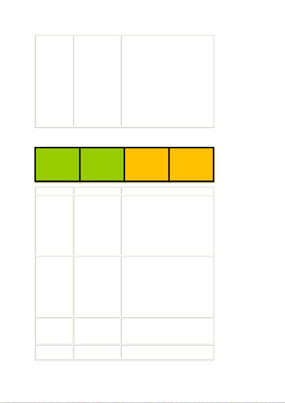
Menus 32-35 Change Active Memory 7/8
- 41 -
Page 42
Eyeheight Limited, Sutton Business Centre, Restmor Way, Wallington, Surrey SM6 7AH
Reg. No. 2855535 Telephone: +44 (0) 208 255 2015 Fax: +44 (0) 208 241 6951 email: [email protected]
35
Back
Pressing the button takes you to
the previous level of menus (Go
To Menus 04-07)
Pressing the next button on the
panel will take you to the next
menu in the nested menu
sequence (Go To Menus 36-39)
Pressing the prev button on the
panel will take you to the previous
menu in the nested menu
sequence (Go To Menus 28-31)
Menu Num.
Heading
Function
36
Load memory
„User define
mem11‟
Pressing this button will load
memory 22 of 64
This will change the panel display
to „please wait‟, and will return
after a short delay to the ARC
Memory Select Top Menus (Go
To Menus 04-07)
37
Load memory
„User define
mem12‟
Pressing this button will load
memory 23 of 64
This will change the panel display
to „please wait‟, and will return
after a short delay to the ARC
Memory Select Top Menus (Go
To Menus 04-07)
38
More user
memories…
Pressing this will give you access
to the remaining user defined
memories (Go To Menus 40-43)
39
Back
Pressing the button takes you to
the previous level of menus (Go
User
define
mem11
User
define
mem12
more
user
mems..
*BACK*
prev
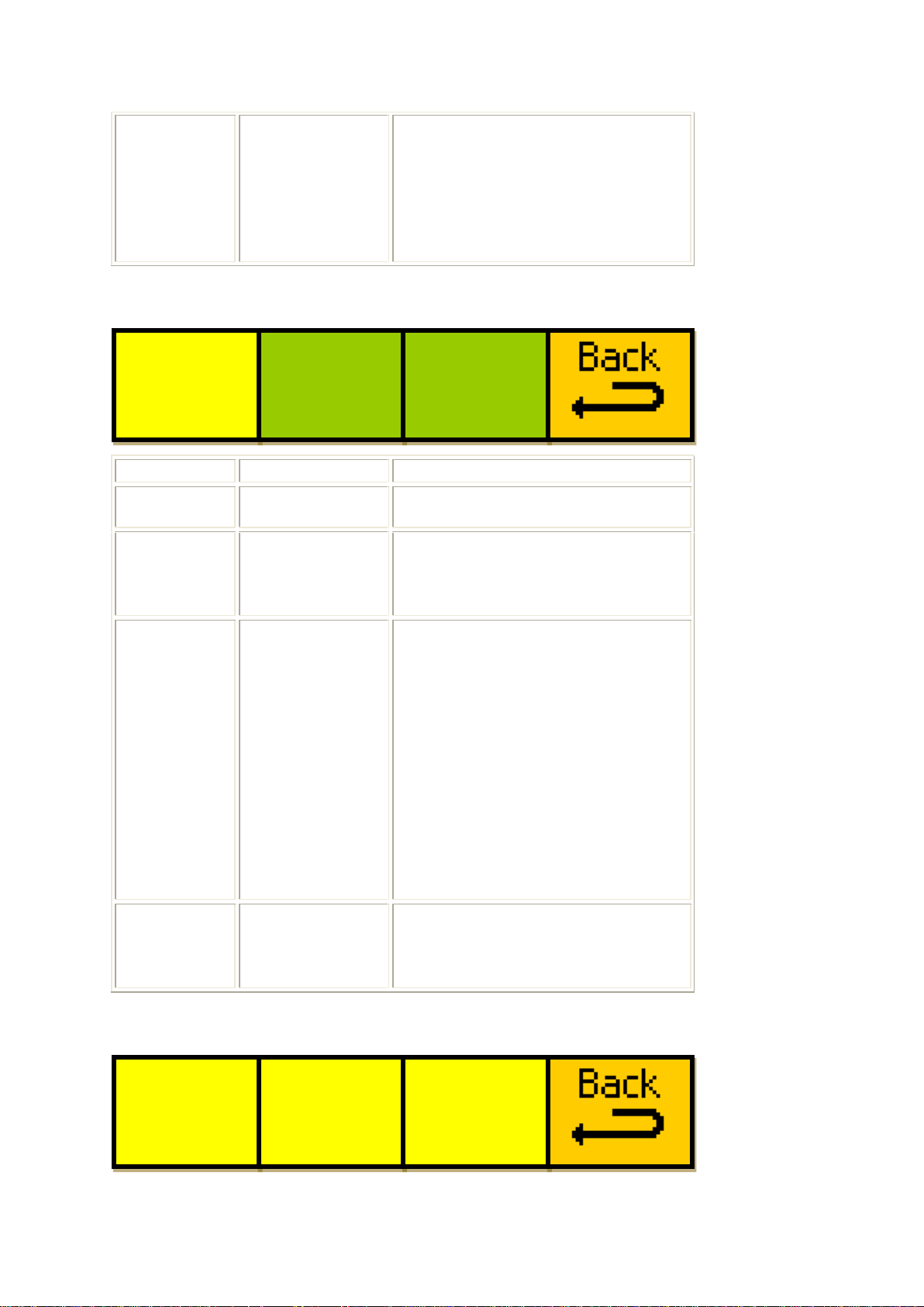
Menus 36-39 Change Active Memory 8/8
- 42 -
Page 43
Eyeheight Limited, Sutton Business Centre, Restmor Way, Wallington, Surrey SM6 7AH
Reg. No. 2855535 Telephone: +44 (0) 208 255 2015 Fax: +44 (0) 208 241 6951 email: [email protected]
To Menus 04-07)
Pressing the prev button on the
panel will take you to the previous
menu in the nested menu
sequence (Go To Menus 32-35)
Menu Num.
Heading
Function
40
---
---
41
User memory
0 – 40
This button selects which user
memory you want to load,
between memories 24 and 64.
42
Apply
This will load the memory
selected in the above menu (41).
This will change the panel display
to „please wait‟, and will return
after a short delay to the ARC
Memory Select Top Menus (Go
To Menus 04-07)
Note: If the memory selected is
not valid, this menu icon will be
locked.
43
Back
Pressing the button takes you to
the previous level of menus (Go
To Menus 36-39)
Defini
Frame
Frame
tion->
form->
rate->
625
I
50
Select
Memory
----->
User
define
mem13
-----APPLY
------
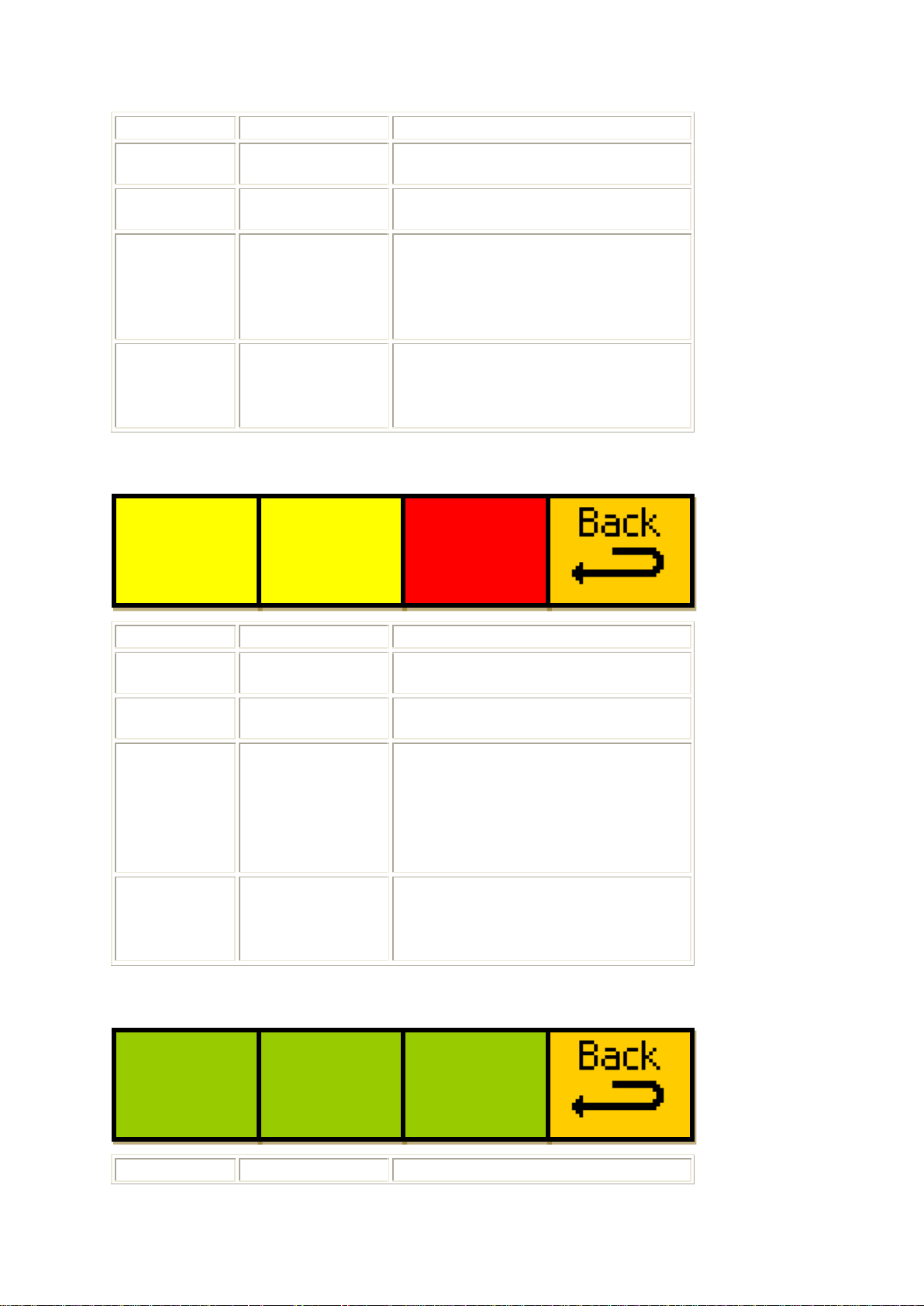
Menus 40-43 Change Active Memory, Memories 13-53 Menus
Menus 44-47 Video Input Menus
- 43 -
Page 44
Eyeheight Limited, Sutton Business Centre, Restmor Way, Wallington, Surrey SM6 7AH
Reg. No. 2855535 Telephone: +44 (0) 208 255 2015 Fax: +44 (0) 208 241 6951 email: [email protected]
Menu Num.
Heading
Function
44
---
---
45
---
---
46
Input Video
Standard
This icon indicates the currently
detected input video standard
(will show „No Video Input‟ if no
valid video is detected)
47
Back
Pressing the button takes you to
the previous level of menus (Go
To Menus 148-151)
Menu Num.
Heading
Function
48
---
---
49
---
---
50
50
Output Video
Standard
This menu selects the output
video standard.
Details of this menu can be found
in section 4.4.1
51
Back
Pressing the button takes you to
the previous level of menus (Go
To Menus 148-151)
Menu Num.
Heading
Function
GNR
= 0
BAR
= 0
MNR
= 0
Defini
Frame
Frame
tion->
form->
rate->
625
I
50
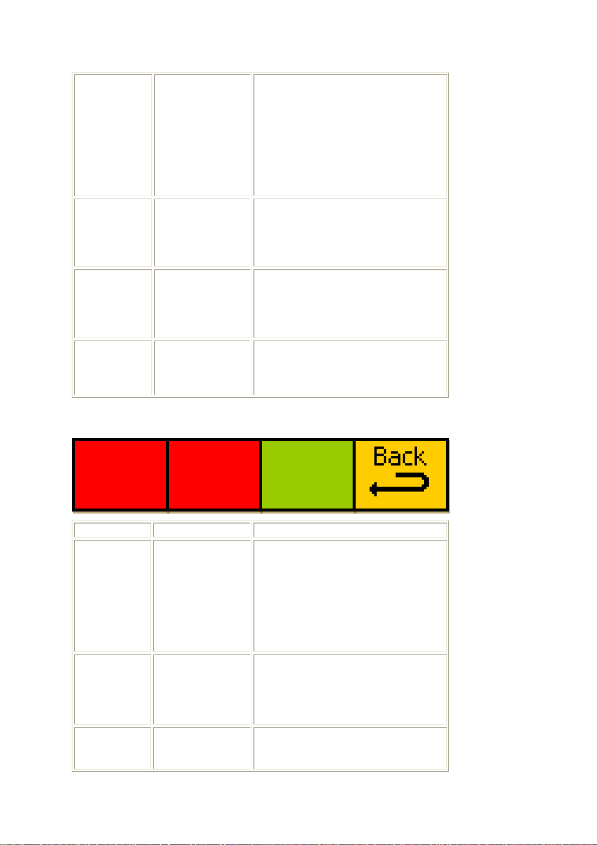
Menus 48-51 Video Output Menus
Menus 52-55 Noise Reduction Menus
- 44 -
Page 45
Eyeheight Limited, Sutton Business Centre, Restmor Way, Wallington, Surrey SM6 7AH
Reg. No. 2855535 Telephone: +44 (0) 208 255 2015 Fax: +44 (0) 208 241 6951 email: [email protected]
52
General Noise
Reduction
This changes the general noise
reduction level that is applied to
the output video, range 0 (off), to
63 (maximum noise reduction).
An explanation of the Noise
Reduction feature is given in
section 4.5.4.1
53
Block Artefact
Removal
This changes the block artefact
removal level that is applied to
the output video, range 0 (off), to
63 (maximum noise reduction).
54
Mosquito Noise
Removal
This changes the mosquito noise
reduction level that is applied to
the output video, range 0 (off), to
63 (maximum noise reduction).
55
Back
Pressing the button takes you to
the previous level of menus (Go
To Menus 152-155)
Menu Num.
Heading
Function
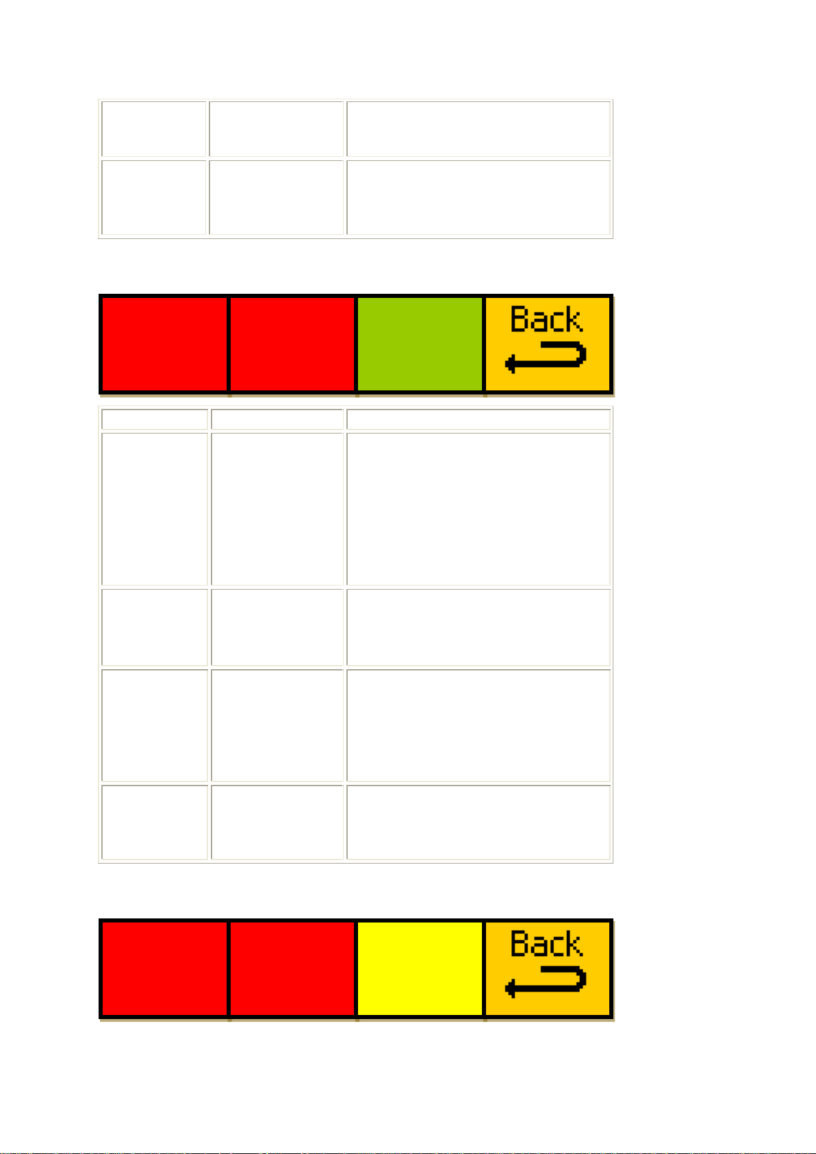
56
Edge
Sharpness
Adjustment
This menu adjusts the level of
edge sharpening applied to the
output video.
An explanation of the Edge
Sharpening feature is given in
section 4.5.4.2
57
Edge
Sharpness
Adjustment and
Overshoot
Control
This menu adjusts the level of
edge sharpening applied to the
output video.
58
Sharpness
Enable
This menu enables or disables
the edge sharpening effect. If set
to off, the settings above are
Sharp
H=0
V=0
Sharp
D=0
OC=0
Sharp
enable
= OFF
Menus 56-59 Edge Sharpness menus
- 45 -
Page 46
Eyeheight Limited, Sutton Business Centre, Restmor Way, Wallington, Surrey SM6 7AH
Reg. No. 2855535 Telephone: +44 (0) 208 255 2015 Fax: +44 (0) 208 241 6951 email: [email protected]
ignored and no edge sharpening
will be performed.
59
Back
Pressing the button takes you to
the previous level of menus (Go
To Menus 152-155)
Menu Num.
Heading
Function
60
Texture
Enhancement
Level
Adjustment
This menu adjusts the level of
texture enhancement applied to
the output video.
An explanation of the Texture
Enhancement feature is given in
section 4.5.4.2
61
Texture
Enhancement
Level
Adjustment
This menu adjusts the level of
texture enhancement applied to
the output video.
62
Texture Enable
This menu enables or disables
the texture enhancement effect.
If set to off, the settings above
are ignored and no texture
enhancement will be performed.
63
Back
Pressing the button takes you to
the previous level of menus (Go
To Menus 152-155)
Sh+Txt
Y only
= OFF
Sh+Txt
NA Lim
= 0
Txture
H=0
V=0
Txture
C=0
OC=0
Txture
enable
= OFF
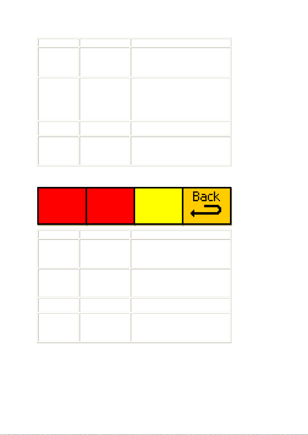
Menus 60-63 Texture Enhancement menus
Menus 64-67 Misc. Sharpness and Texture menus
- 46 -
Page 47
Eyeheight Limited, Sutton Business Centre, Restmor Way, Wallington, Surrey SM6 7AH
Reg. No. 2855535 Telephone: +44 (0) 208 255 2015 Fax: +44 (0) 208 241 6951 email: [email protected]
Menu Num.
Heading
Function
64
Sharpness and
Texture apply
to Y channel
only
This menu allows for more
specific channel targeting for the
sharpness and texture effects.
65
Sharpness and
Texture Noise
Adaption Limit
This menu adjusts the noise
adaption threshold for the
sharpness and texture effects.
Range is 0 (no noise adaption) to
63 (full noise adaption).
66
---
---
67
Back
Pressing the button takes you to
the previous level of menus (Go
To Menus 156-159)
Menu Num.
Heading
Function
68
Output Picture
Size
This menu sets the Horizontal
and Vertical output picture size, in
pixels.
69
Output Picture
Position
This menu sets the horizontal and
vertical output picture position, in
pixels.
70
---
---
71
Back
Pressing the button takes you to
the previous level of menus (Go
To Menus 132-135)
Size
H=720
V=576
Positn
H+0
V+0
Menus 68-71 Aspect Ratio Menus
Menus 72-75 Picture Blanking Menus
- 47 -
Page 48
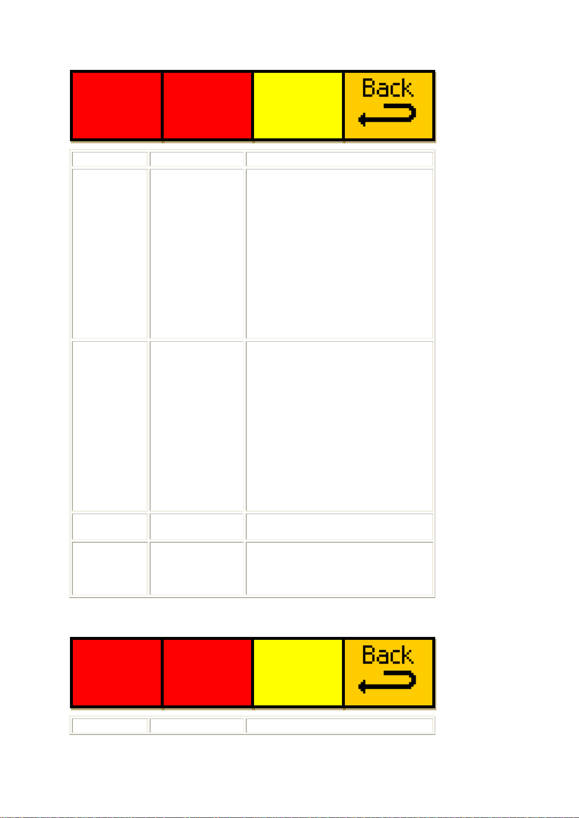
Eyeheight Limited, Sutton Business Centre, Restmor Way, Wallington, Surrey SM6 7AH
Reg. No. 2855535 Telephone: +44 (0) 208 255 2015 Fax: +44 (0) 208 241 6951 email: [email protected]
Menu Num.
Heading
Function
72
Blanking
This menu sets the amount of
blanking applied to the input
video source before processing,
in lines.
„T‟ is the number of horizontal
lines from the top of the picture
that will be blanked.
„B‟ is the number of horizontal
lines from the bottom of the
picture that will be blanked.
73
Blanking
This menu sets the amount of
blanking applied to the input
video source before processing,
in lines.
„L‟ is the number of vertical lines
from the left of the picture that will
be blanked.
„R‟ is the number of vertical lines
from the right of the picture that
will be blanked.
74
---
---
75
Back
Pressing the button takes you to
the previous level of menus (Go
To Menus 132-135)
Menu Num.
Heading
Function
Blnkng
T=0
B=0
Blnkng
L=0
R=0
Triggr
=OFF
RCL if
val=0
mem=1
16F16
to
16L12
Menus 76-79 Signalling Menus
- 48 -
Page 49
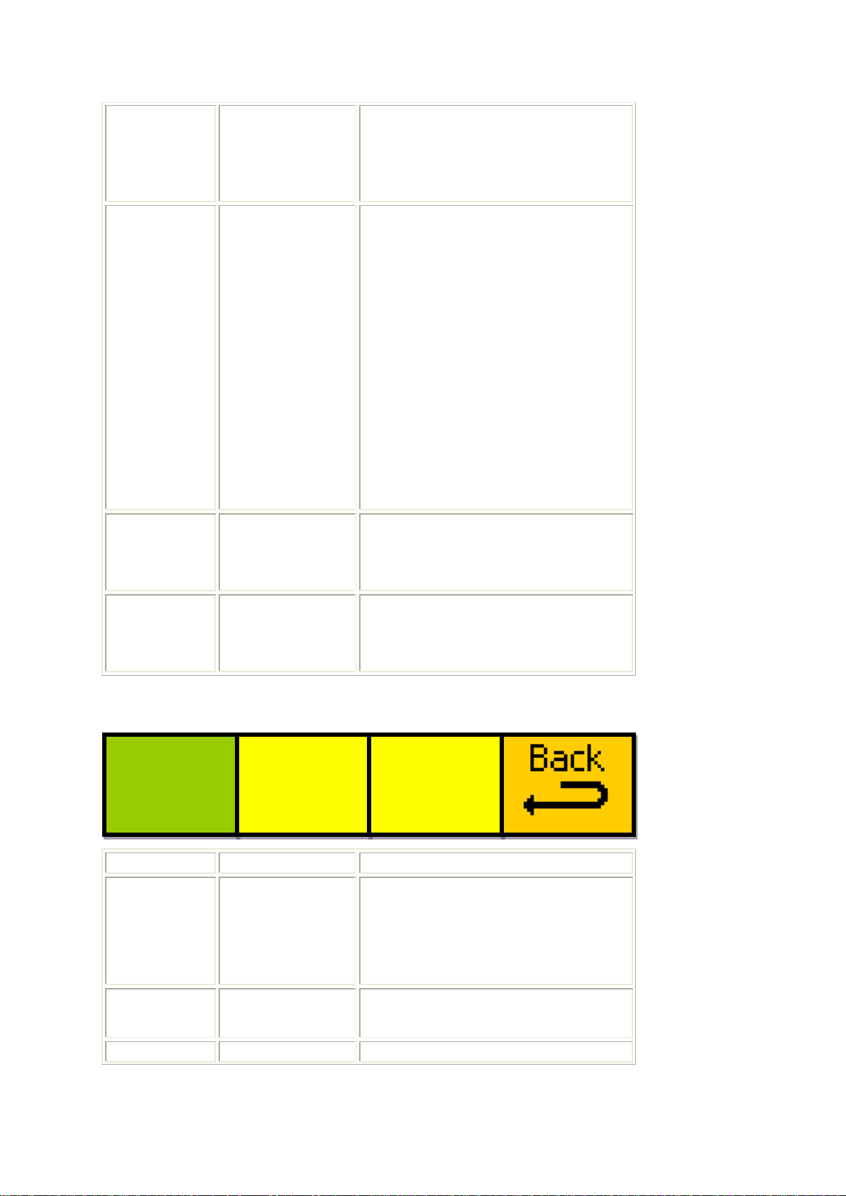
Eyeheight Limited, Sutton Business Centre, Restmor Way, Wallington, Surrey SM6 7AH
Reg. No. 2855535 Telephone: +44 (0) 208 255 2015 Fax: +44 (0) 208 241 6951 email: [email protected]
76
Aspect Ratio
change trigger
target
This menu sets the source of the
data embedded in the video
stream used to load memories
automatically.
77
Memory recall
for a given
target value
This menu sets up the memories
to be recalled for the 8 possible
values of the detection method
specified in the „Trigger‟ menu
above (76).
„mem‟ is the number of the
memory you want recalled for
that signalling value.
„val‟ is the value that the memory
specified will apply to.
A more in-depth explanation is
given in section 4.4.5
78
Target memory
name
This menu displays the name of
the memory currently selected in
menu 77.
79
Back
Pressing the button takes you to
the previous level of menus (Go
To Menus 140-143)
Menu Num.
Heading
Function
80
Audio delay
This menu sets the delay that will
be applied to the audio stream.
Units are in number of fields of
the input video.
81
---
--82
---
---
Audio
delay
=2 fi
Menus 80-83 Audio Menus
- 49 -
Page 50
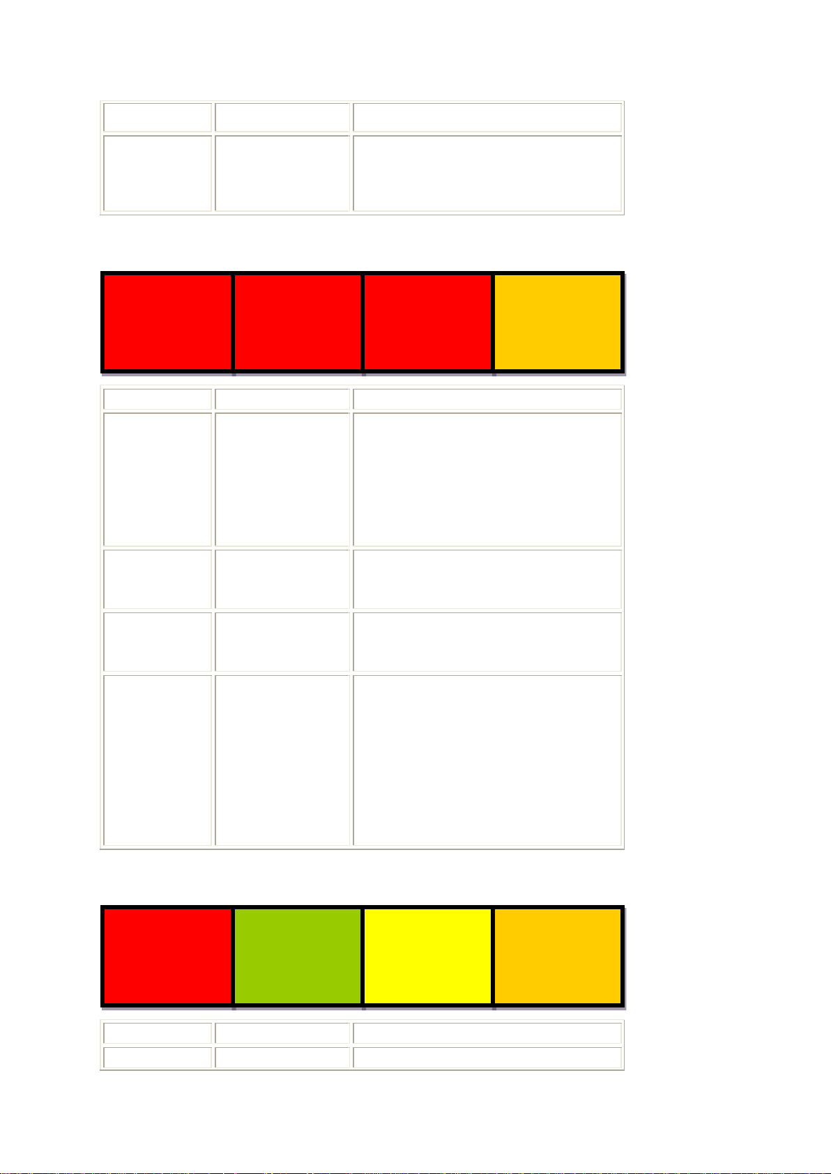
Eyeheight Limited, Sutton Business Centre, Restmor Way, Wallington, Surrey SM6 7AH
Reg. No. 2855535 Telephone: +44 (0) 208 255 2015 Fax: +44 (0) 208 241 6951 email: [email protected]
83
Back
Pressing the button takes you to
the previous level of menus (Go
To Menus 136-139)
Menu Num.
Heading
Function
84
GPI #1 Setup
This menu sets up the state of
the on-board GPI #1.
A detailed explanation of how the
GPIs work can be found in
section 4.4.4
85
GPI #2 Setup
This menu sets up the state of
the on-board GPI #2.
86
GPI #3 Setup
This menu sets up the state of
the on-board GPI #3.
87
Back
Pressing this button takes you to
the previous level of menus (Go
To Menus 140-143)
Pressing the next button on the
panel will take you to the next
menu in the nested menu
sequence (Go To Menus 88-91)
Menu Num.
Heading
Function
88
GPI #4 Setup
This menu sets up the state of
#4=OFF
LH=0
HL=0
GPO #1
=OFF
*BACK*
prev
#1=OFF
LH=0
HL=0
#2=OFF
LH=0
HL=0
#3=OFF
LH=0
HL=0
next
*BACK*
Menus 84-87 GPI/O Menus 1/2
Menus 88-91 GPI/O Menus 2/2
- 50 -
Page 51
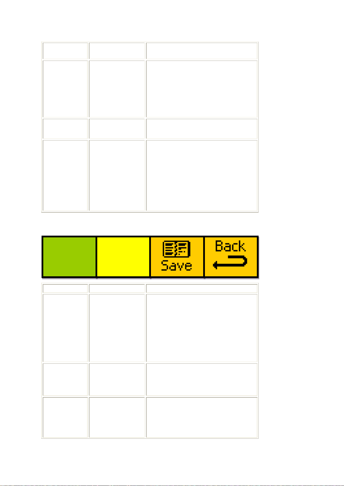
Eyeheight Limited, Sutton Business Centre, Restmor Way, Wallington, Surrey SM6 7AH
Reg. No. 2855535 Telephone: +44 (0) 208 255 2015 Fax: +44 (0) 208 241 6951 email: [email protected]
the on-board GPI #4.
89
GPO #1 Enable
This menu turns GPO #1 off or
on.
If set to „on‟, the GPO #1 line will
be triggered if the input video to
the AR-2N becomes invalid.
90
---
---
91
Back
Pressing this button takes you to
the previous level of menus (Go
To Menus 140-143)
Pressing the prev button on the
panel will take you to the previous
menu in the nested menu
sequence (Go To Menus 84-87)
Menu Num.
Heading
Function
92
Save settings
to target
memory
This menu selects the target
memory to be overwritten when
the current settings are saved.
A more detailed explanation of
saving user settings is given in
section 4.5.6
93
Target memory
name
This menu displays the name of
the memory selected in the above
menu (92).
94
Save memory
sub-menu
Pressing this button takes you to
the save memory menu set,
which also allows editing of the
save name via panel controls (Go
To Menus 96-)
Save
to:
mem 1
User
define
mem01
Menus 92-96 Select Save Memory Location Menus
- 51 -
Page 52
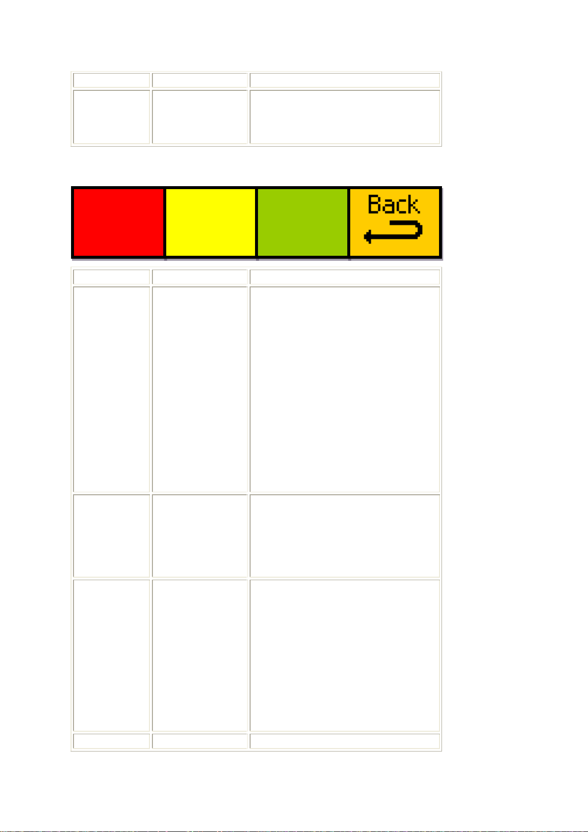
Eyeheight Limited, Sutton Business Centre, Restmor Way, Wallington, Surrey SM6 7AH
Reg. No. 2855535 Telephone: +44 (0) 208 255 2015 Fax: +44 (0) 208 241 6951 email: [email protected]
95
Back
Pressing the button takes you to
the previous level of menus (Go
To Menus 160-163)
Menu Num.
Heading
Function
96
Edit memory
name
This menu allows you to edit the
user memory name for the
memory you are about to save.
„Pos‟ reflects which character is
going to be changed.
„val‟ is the number used in the
memory naming lookup table,
which determines the character
used in the specified location.
The lookup table used is
specified in section 4.5.6
97
Edited memory
name
This menu contains the name of
the memory you are about to
save, which is updated constantly
as it‟s changed using the controls
in the above menu (96).
98
Save memory
Pressing this button will save the
current settings of the AR-2N to
the memory specified in menu 92,
with the edited memory name
specified in menu 97.
When pressed, the display will
show „SAVED!‟ briefly to let you
know the operation was
successful.
99
Back
Pressing the button takes you to
Edit->
Pos 1
val 53
User
define
mem01
!Save!
!!To!!
!Mem!!
Menus 96-99 Save Settings Menus
- 52 -
Page 53
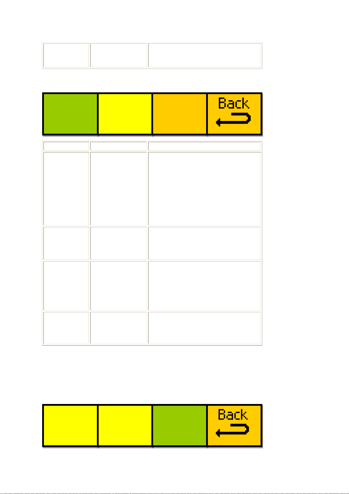
Eyeheight Limited, Sutton Business Centre, Restmor Way, Wallington, Surrey SM6 7AH
Reg. No. 2855535 Telephone: +44 (0) 208 255 2015 Fax: +44 (0) 208 241 6951 email: [email protected]
the previous level of menus (Go
To Menus 92-96)
Menu Num.
Heading
Function
100
View memory
number
This menu specifies the user
memory you wish to view.
Preset memories are not
viewable, so the range is 1 – 53.
An explanation of this function is
given in section 4.5.7
101
Selected
memory name
This is a display of the name of
the currently selected memory
you have selected to view.
102
View
Pressing this button takes you to
the „view memory‟ set of menus,
which display all of the
information stored in the selected
memory (Go To Menus 180-183)
103
Pressing the button takes you to
the previous level of menus (Go
To Menus 160-163)
View
memory
no. 1
User
define
mem01
----- view
------
START?
Softwr
ARE
YOU
SURE?
----- YES
------
Menus 100-103 View Memory Select Menus
Menus 104-107
Menus 104-107 are not accessible by the user.
Menus 108-111 Software Update Confirmation Menus
- 53 -
Page 54
Eyeheight Limited, Sutton Business Centre, Restmor Way, Wallington, Surrey SM6 7AH
Reg. No. 2855535 Telephone: +44 (0) 208 255 2015 Fax: +44 (0) 208 241 6951 email: [email protected]
Menu Num.
Heading
Function
108
---
--- 109
---
---
110
Software
upgrade
confirmation
Pressing this button will confirm
you want to update the software
of the AR-2N, and will jump to the
message displayed on Menus
168-171.
The details of the update
procedure can be found in
section 4.6
111
Pressing the button takes you to
the previous level of menus (Go
To Menus 112-115)
Menu Num.
Heading
Function
112
AR-2N software
version
This displays the software version
of the AR-2N, as well as the date
the software was created (in the
form dd mm yy).
113
AR-2N video
processing
software
version
This displays the version of the
video processing software used
to control the hardware of the AR-
2N, as well as the date it was
created (in the form dd mm yy).
114
Upgrade
software submenu
Pressing this button will take you
to the software update
confirmation menu (Go To
Menus 108-111)
115
Pressing the button takes you to
the previous level of menus (Go
AR-2
010108
v1.00
VIPER
010108
v1.00
Upgrde
Softwr
Now!!!
Menus 112-115 Software Versions Menus
- 54 -
Page 55
Eyeheight Limited, Sutton Business Centre, Restmor Way, Wallington, Surrey SM6 7AH
Reg. No. 2855535 Telephone: +44 (0) 208 255 2015 Fax: +44 (0) 208 241 6951 email: [email protected]
To Menus 164-167)
Menu Num.
Heading
Function
116
Warm Start
Pressing this button will make the
AR-2N perform a warm start,
which has a similar effect to
power cycling.
Be aware that this will be likely to
cause temporary loss of output
video while the unit loads the new
settings.
The AR-2N will return to the top
level menu in 20-30 seconds.
117
Factory Reset
Pressing this button will take you
to the factory reset confirmation
menu (Go To Menus 120-123)
118
---
---
119
Back
Pressing the button takes you to
the previous level of menus (Go
To Menus 164-167)
Menu Num.
Heading
Function
120
---
---
121
---
---
START?
Factry
ARE
YOU
SURE?
----- YES
------
Reboot
this
unit
Factry
reset
Menus 116-119 Resets Menus
Menus 120-123 Factory Reset Confirmation Menus
- 55 -
Page 56
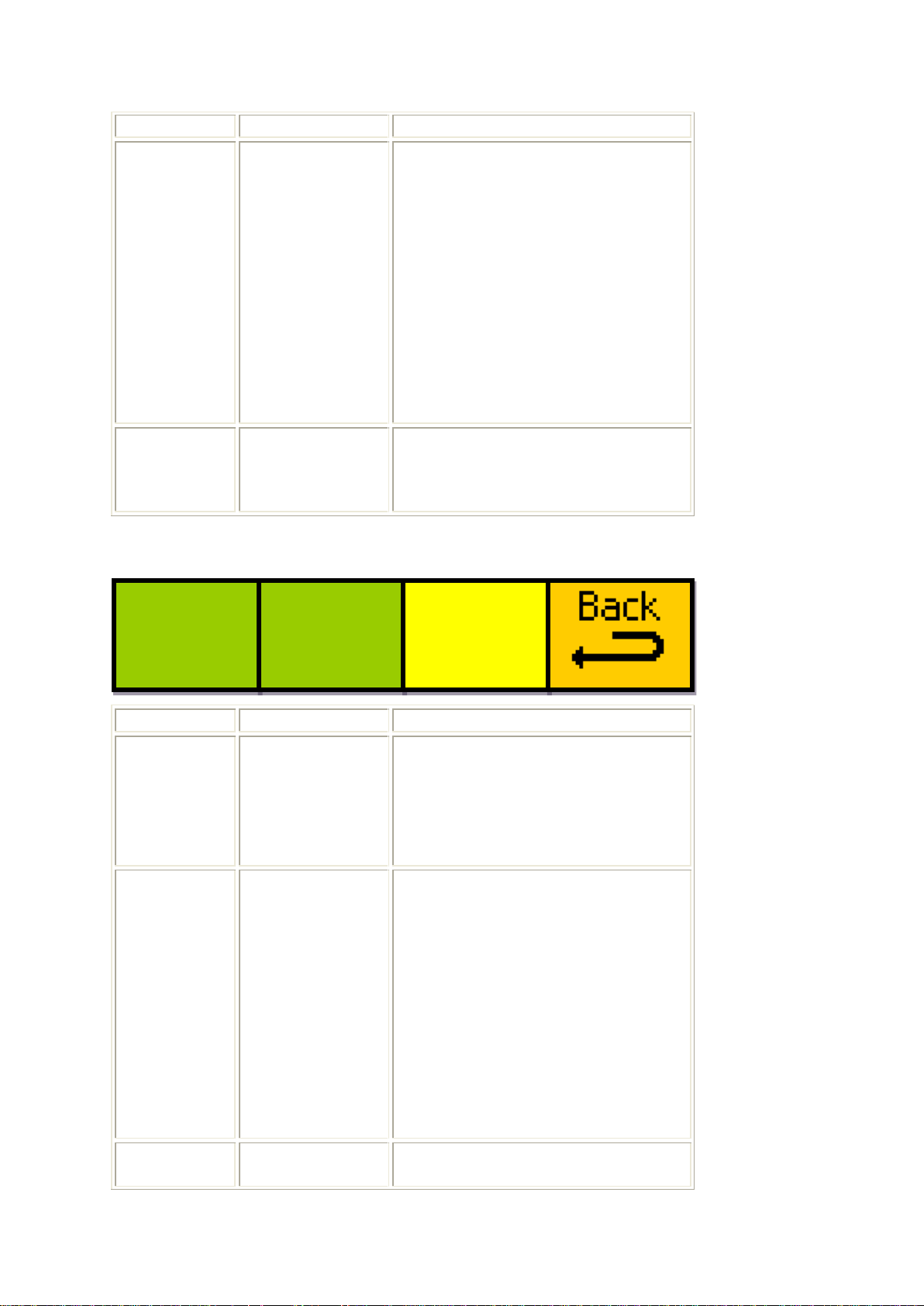
Eyeheight Limited, Sutton Business Centre, Restmor Way, Wallington, Surrey SM6 7AH
Reg. No. 2855535 Telephone: +44 (0) 208 255 2015 Fax: +44 (0) 208 241 6951 email: [email protected]
122
Factory Reset
confirmation
Pressing this button will confirm
you want to perform reset the AR-
2N to its factory settings. The
menu icon will change to „please
wait‟ while the action is
performed.
WARNING! Performing a factory
reset will permanently erase all
user memories that have been
stored, as well as erasing the
current power-on default setting.
123
Back
Pressing the button takes you to
the previous level of menus (Go
To Menus 116-119)
Menu Num.
Heading
Function
124
Auto Arc
Manipulation
This menu sets the desired
output of the auto-arc mode.
A detailed explanation of this
setting is given in section 4.5.5
125
Clear all vars
Pressing this button will reset
numerous user definable values
within the AR-2N.
The menu will briefly display the
message „all vars cleared‟ when
the operation is completed
successfully (this is usually
almost instant).
A detailed explanation of this
setting is given in section 4.5.5
126
---
---
AAM=
No Img
Crop
Clear
All
Vars
Menus 124-127 Misc. Global Settings Menus
- 56 -
Page 57
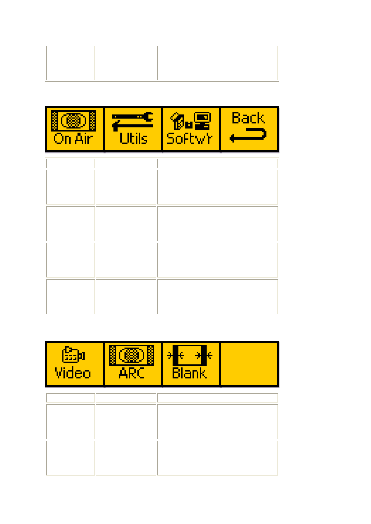
Eyeheight Limited, Sutton Business Centre, Restmor Way, Wallington, Surrey SM6 7AH
Reg. No. 2855535 Telephone: +44 (0) 208 255 2015 Fax: +44 (0) 208 241 6951 email: [email protected]
127
Pressing the button takes you to
the previous level of menus (Go
To Menus 156-159)
Menu Num.
Heading
Function
128
On air submenu
Pressing this button will take you
to the ARC memory select top
menu (Go To Menus 04-07)
129
Utilities submenu
Pressing this button will take you
to the first of the utilities menus
(Go To Menus 132-135)
130
Memories,
versions and
resets menu
Pressing this button will take you
to the Software menu (Go To
Menus 164-167)
131
Back
Pressing the button takes you to
the previous level of menus (Go
To Menus 00-03)
Menu Num.
Heading
Function
132
Video menu
Pressing this button will take you
to the Video Settings Menus (Go
To Menus 148-151)
133
Aspect Ratio
menu
Pressing this button will take you
to the Aspect Ratio Menus (Go
To
Menus 68-71)
next
*BACK*
Menus 128-131 Main Menu Set 2/2
Menus 132-135 Utilities Menu 1/2
- 57 -
Page 58
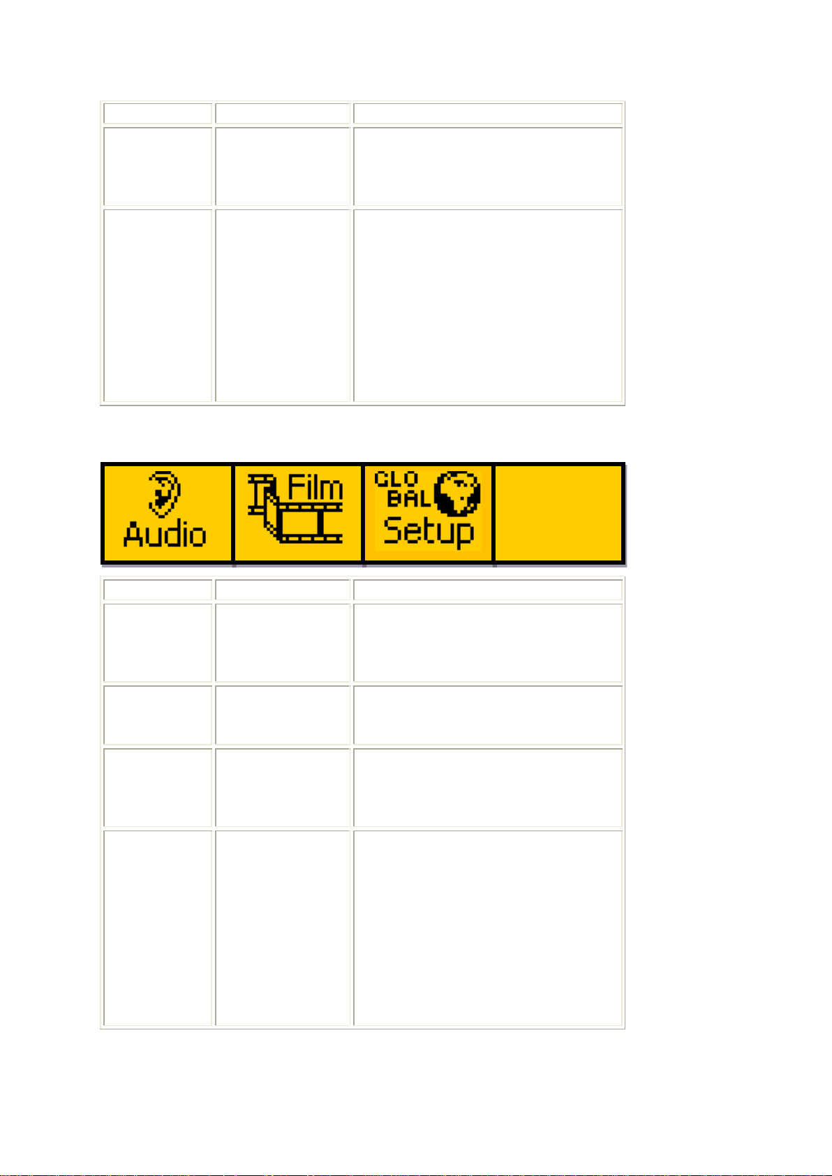
Eyeheight Limited, Sutton Business Centre, Restmor Way, Wallington, Surrey SM6 7AH
Reg. No. 2855535 Telephone: +44 (0) 208 255 2015 Fax: +44 (0) 208 241 6951 email: [email protected]
134
Picture
Blanking menu
Pressing this button will take you
to the Picture Blanking Menus
(Go To Menus 72-75)
135
Back
Pressing this button takes you to
the previous level of menus (Go
To Menus 128-131)
Pressing the next button on the
panel will take you to the next
menu in the nested menu
sequence (Go To Menus 136-
139)
Menu Num.
Heading
Function
136
Audio menu
Pressing this button will take you
to the Audio Menus (Go To
Menus 80-83)
137
Film menu
Pressing this button will take you
to the Film mode menus (Go To
Menus 216-219)
138
Global Settings
menu
Pressing this button will take you
to the Global Setup Menus (Go
To Menus 140-143)
139
Back
Pressing this button takes you to
the previous level of menus (Go
To Menus 128-131)
Pressing the prev button on the
panel will take you to the next
menu in the nested menu
sequence (Go To Menus 132-
135)
*BACK*
prev
Menus 136-139 Utilities Menu 2/2
- 58 -
Page 59
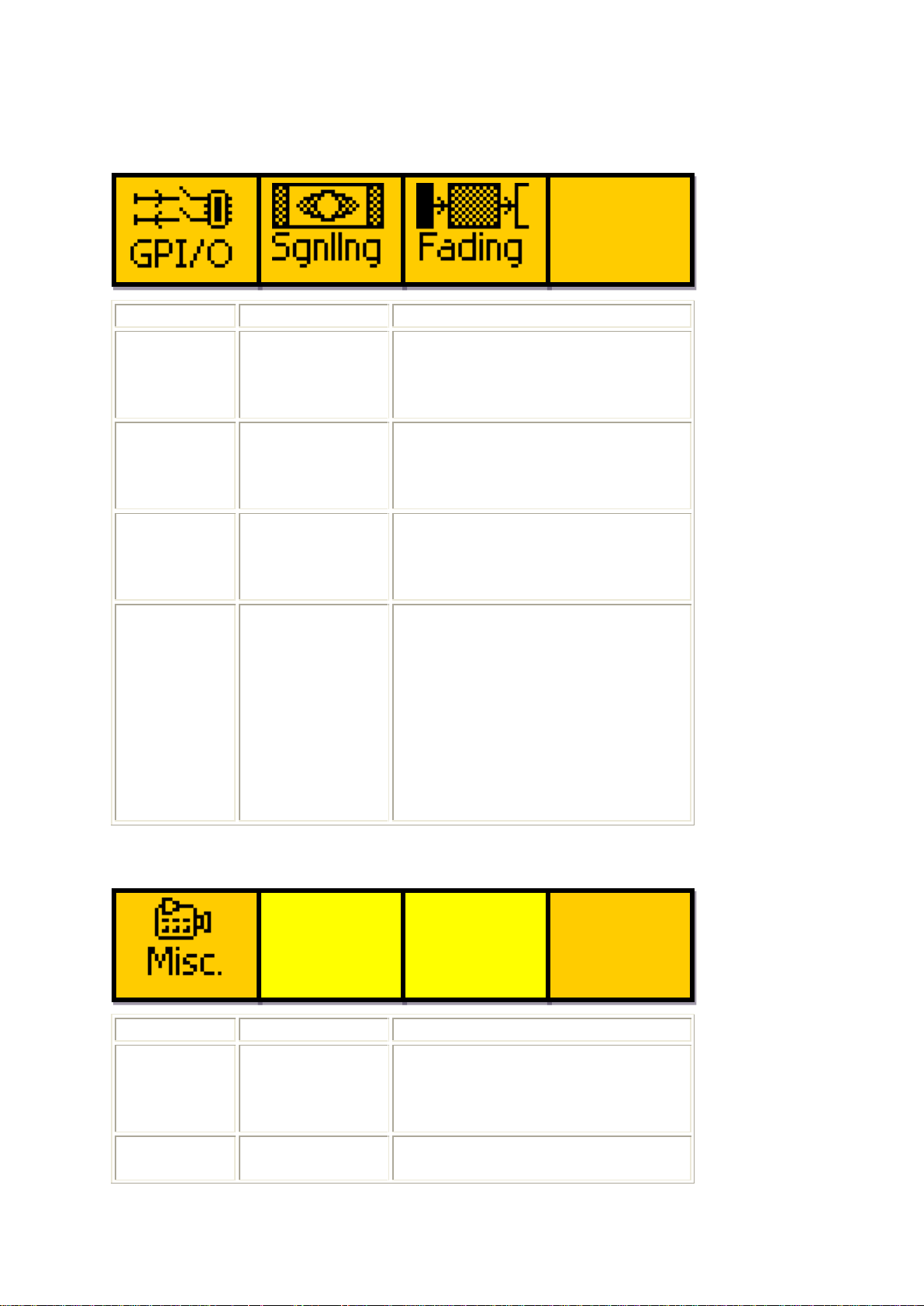
Eyeheight Limited, Sutton Business Centre, Restmor Way, Wallington, Surrey SM6 7AH
Reg. No. 2855535 Telephone: +44 (0) 208 255 2015 Fax: +44 (0) 208 241 6951 email: [email protected]
Menu Num.
Heading
Function
140
GPI/O menu
Pressing this button will take you
to the GPI/O Menus (Go To
Menus 84-87)
141
Signalling
menu
Pressing this button will take you
to the Signalling Menus (Go To
Menus 76-79)
142
Transitions
menu
Pressing this button will take you
to the Transitions Menus (Go To
Menus 208-211)
143
Back
Pressing this button takes you to
the previous level of menus (Go
To Menus 136-139)
Pressing the next button on the
panel will take you to the next
menu in the nested menu
sequence (Go To Menus 144-
147)
Menu Num.
Heading
Function
144
Global Setup
Misc. Menu
Pressing this button will take you
to the Misc. Global Settings
Menus (Go To Menus 124-127)
145
---
---
*BACK*
prev
next
*BACK*
Menus 140-143 Global Setup Menus 1/2
Menus 144-147 Global Setup Menus 2/2
- 59 -
Page 60
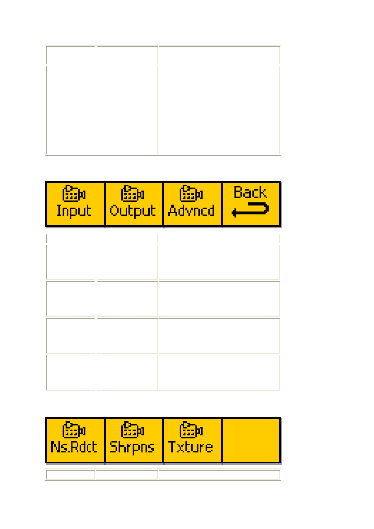
Eyeheight Limited, Sutton Business Centre, Restmor Way, Wallington, Surrey SM6 7AH
Reg. No. 2855535 Telephone: +44 (0) 208 255 2015 Fax: +44 (0) 208 241 6951 email: [email protected]
146
---
---
147
Back
Pressing this button takes you to
the previous level of menus (Go
To Menus 136-139)
Pressing the prev button on the
panel will take you to the next
menu in the nested menu
sequence (Go To Menus 140-
143)
Menu Num.
Heading
Function
148
Video Input
Menu
Pressing this button will take you
to the Video Input Menus (Go To
Menus 44-47)
149
Video Output
Menu
Pressing this button will take you
to the Video Output Menus (Go
To Menus 48-51)
150
Advanced
Video Menu
Pressing this button will take you
to the Advanced Video Settings
Menus (Go To Menus 152-155)
151
Back
Pressing the button takes you to
the previous level of menus (Go
To Menus 132-135)
Menu Num.
Heading
Function
next
*BACK*
Menus 148-151 Video Settings Menus
Menus 152-155 Advanced Video Settings Menus 1/2
- 60 -
Page 61
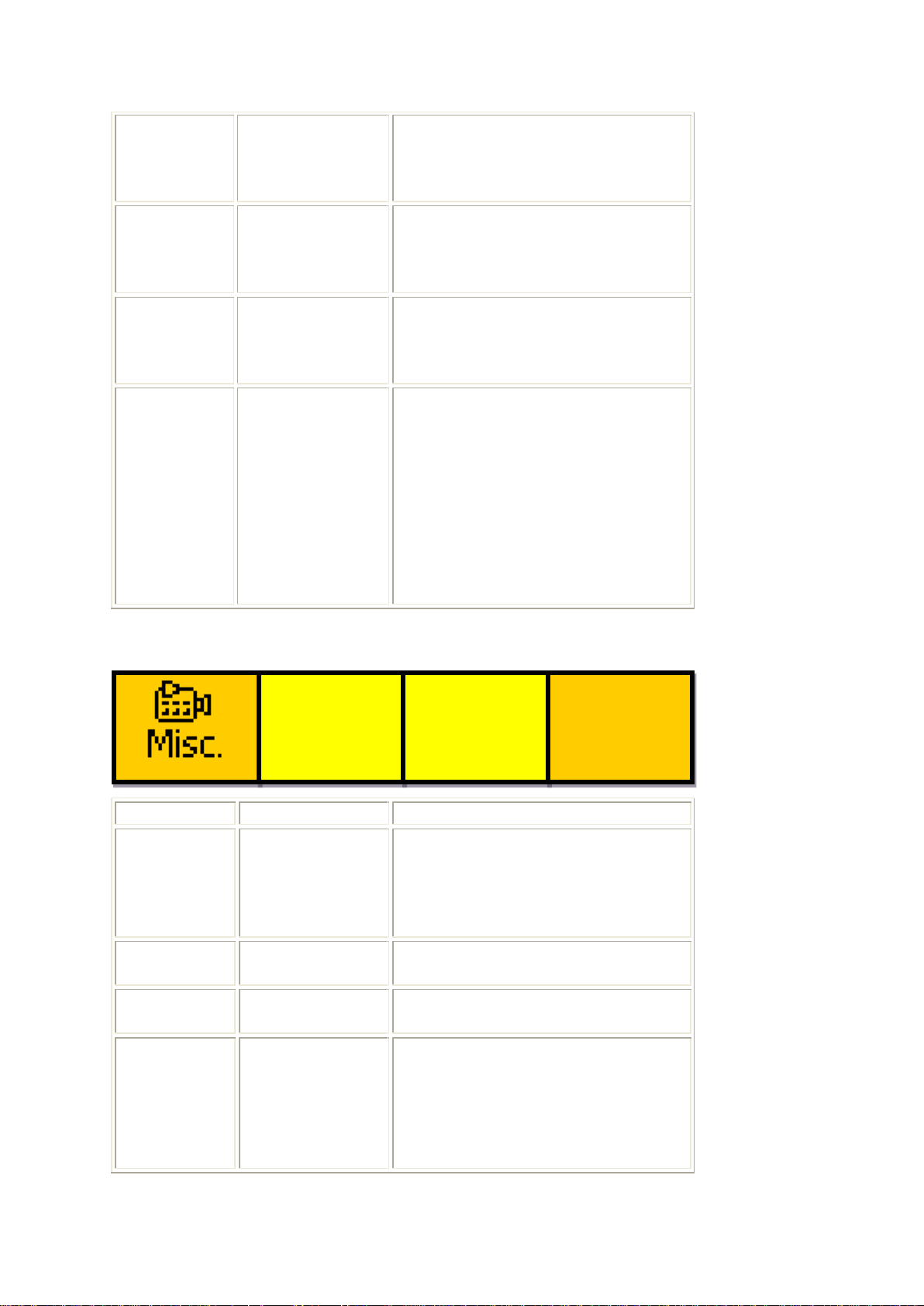
Eyeheight Limited, Sutton Business Centre, Restmor Way, Wallington, Surrey SM6 7AH
Reg. No. 2855535 Telephone: +44 (0) 208 255 2015 Fax: +44 (0) 208 241 6951 email: [email protected]
152
Noise
Reduction
Menus
Pressing this button will take you
to the Noise Reduction Menus
(Go To Menus 52-55)
153
Edge
Sharpness
Menu
Pressing this button will take you
to the Edge Sharpness menus
(Go To Menus 56-59)
154
Texture
Enhancement
Menu
Pressing this button will take you
to the Texture Enhancement
menus (Go To Menus 60-63)
155
Back
Pressing this button takes you to
the previous level of menus (Go
To Menus 148-151)
Pressing the next button on the
panel will take you to the next
menu in the nested menu
sequence (Go To Menus 156-
159)
Menu Num.
Heading
Function
156
Advanced
Video Misc.
Menu
Pressing this button will take you
to the Misc. Sharpness and
Texture menus (Go To Menus
64-67) 157
---
---
158
---
---
159
Back
Pressing this button takes you to
the previous level of menus (Go
To Menus 148-151)
Pressing the prev button on the
panel will take you to the next
*BACK*
prev
Menus 156-159 Advanced Video Settings Menus 2/2
- 61 -
Page 62
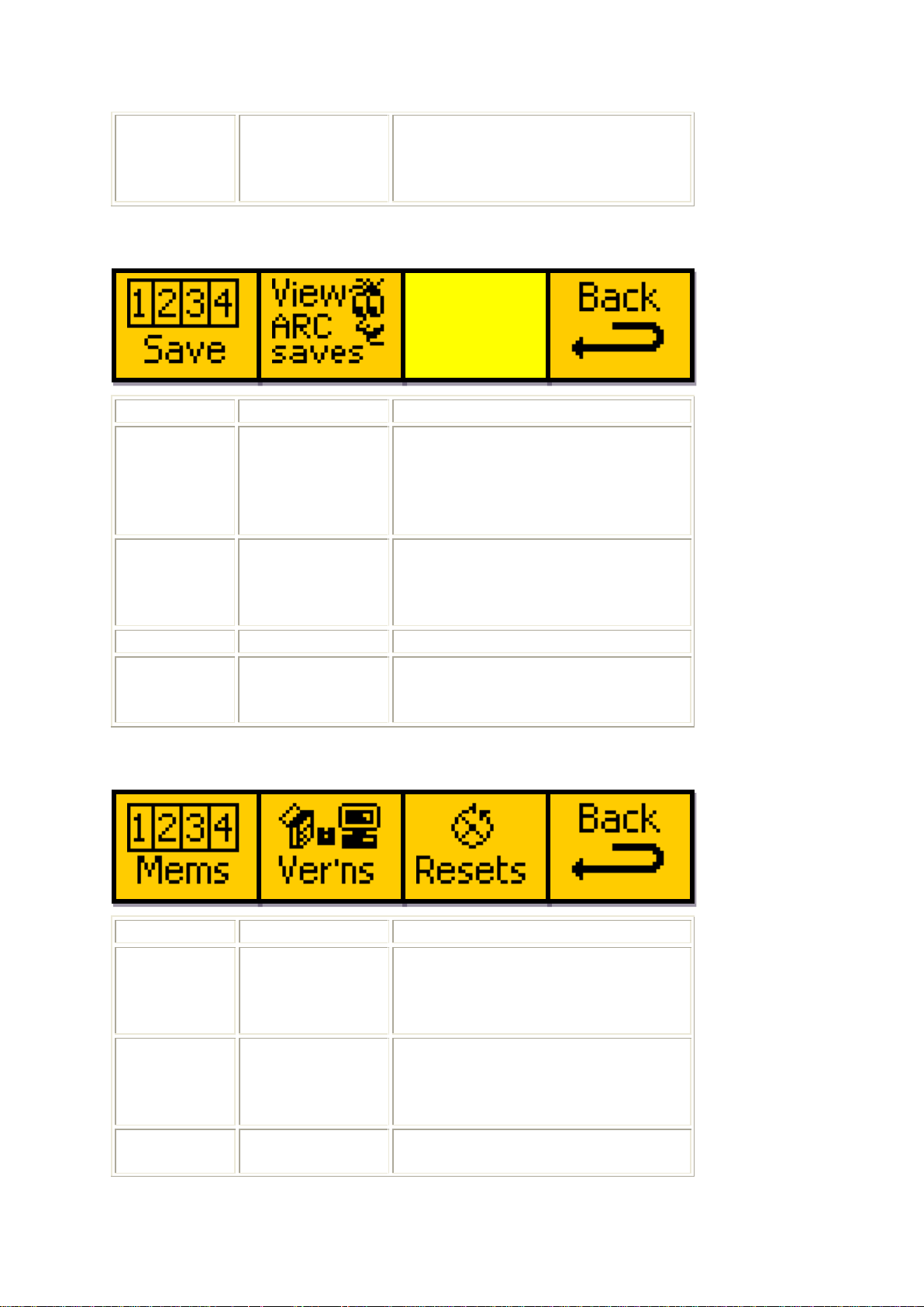
Eyeheight Limited, Sutton Business Centre, Restmor Way, Wallington, Surrey SM6 7AH
Reg. No. 2855535 Telephone: +44 (0) 208 255 2015 Fax: +44 (0) 208 241 6951 email: [email protected]
menu in the nested menu
sequence (Go To Menus 152-
155)
Menu Num.
Heading
Function
160
Save Settings
Menu
Pressing this button will take you
to the Select Save Memory
Location Menus (Go To Menus
92-96)
161
View Memory
Menu
Pressing this button will take you
to the View Memory Select
Menus (Go To Menus 100-103)
162
163
Back
Pressing the button takes you to
the previous level of menus (Go
To Menus 164-167)
Menu Num.
Heading
Function
164
Memories
Menu
Pressing this button will take you
to the Memories Menus (Go To
Menus 160-163)
165
Software
Versions Menu
Pressing this button will take you
to the Software Versions Menus
(Go To Menus 112-115)
166
Resets Menu
Pressing this button will take you
to the Resets Menus (Go To
Menus 160-163 Memories Menus
Menus 164-167 Software Menus
- 62 -
Page 63
Eyeheight Limited, Sutton Business Centre, Restmor Way, Wallington, Surrey SM6 7AH
Reg. No. 2855535 Telephone: +44 (0) 208 255 2015 Fax: +44 (0) 208 241 6951 email: [email protected]
Menus 116-119)
167
Back
Pressing the button takes you to
the previous level of menus (Go
To Menus 128-131)
Menu Num.
Heading
Function
168
---
--- 169
---
--- 170
---
--- 171
---
---
Menu Num.
Heading
Function
172
---
--- 173
---
---
174
---
---
175
---
---
******
PLEASE
WAIT
******
AR-2
FILE
TIMES
IS UPG
IS REC
OUT IN
RADING
EIVED
3 MINS
IF NO
IT
Menus 168-171 Software Upgrade In Progress Menu
Menus 172-175 Performing Operation Menu
- 63 -
Page 64
Eyeheight Limited, Sutton Business Centre, Restmor Way, Wallington, Surrey SM6 7AH
Reg. No. 2855535 Telephone: +44 (0) 208 255 2015 Fax: +44 (0) 208 241 6951 email: [email protected]
Menu Num.
Heading
Function
180
---
---
181
Input Video
Standard
This shows the Input Video
Standard stored in the user
memory.
182
---
---
183
Output Video
Standard
This shows the Output Video
Standard stored in the user
memory.
next button
on panel
---
This will cycle to the next menu in
the nested menu loop (Go To
Menus 184-187)
Menu Num.
Heading
Function
184
Output Picture
Size
This shows the output video
picture size stored in the user
memory.
185
Output Picture
Position
This shows the output video
picture position stored in the user
memory.
ARC
H=720
V=576
info
H+0
V+0
Blnkng
T=0
B=0
info
L=0
R=0
input
video
info
625
I
50
o/p
video
info
625
I
50
Menus 176-179 xxx
These menus are not usable by the user
Menus 180-183 View Memory Display Menus 1/6
Menus 184-187 View Memory Display Menus 2/6
- 64 -
Page 65
Eyeheight Limited, Sutton Business Centre, Restmor Way, Wallington, Surrey SM6 7AH
Reg. No. 2855535 Telephone: +44 (0) 208 255 2015 Fax: +44 (0) 208 241 6951 email: [email protected]
186
Blanking
This shows the Picture blanking
that will apply to the top and
bottom of the input image before
processing, stored in the user
memory.
187
Blanking
This shows the Picture blanking
that will apply to the left and right
of the input image before
processing, stored in the user
memory.
next button
on panel
---
This will cycle to the next menu in
the nested menu loop (Go To
Menus 188-191)
prev button
on panel
---
This will cycle to the previous
menu in the nested menu loop
(Go To Menus 180-183)
Menu Num.
Heading
Function
188
Edge
Sharpening
Level
This shows the level of Horizontal
and Vertical Edge Sharpening
that is stored in the user memory.
189
Edge
Sharpening
and Overshoot
Control Levels
This shows the levels of Diagonal
Edge Sharpening and Overshoot
Control stored in the user
memory.
190
Edge
Sharpening
Enable
This shows if Edge Sharpening is
enabled or disabled in the user
memory.
191
Sharpness and
Texture apply
to Y (Luma)
This shows if The Sharpness and
Texture effects will apply to only
the Y (Luma) channel, or to the
Sharp
H=0
V=0
Sharp
D=0
OC=0
Sharp
enable
= OFF
Sh+Txt
Y only
= OFF
Menus 188-191 View Memory Display Menus 3/6
- 65 -
Page 66
Eyeheight Limited, Sutton Business Centre, Restmor Way, Wallington, Surrey SM6 7AH
Reg. No. 2855535 Telephone: +44 (0) 208 255 2015 Fax: +44 (0) 208 241 6951 email: [email protected]
only
RGB channels independently, as
stored in the user memory.
next button
on panel
---
This will cycle to the next menu in
the nested menu loop (Go To
Menus 192-195)
prev button
on panel
---
This will cycle to the previous
menu in the nested menu loop
(Go To Menus 184-187)
Menu Num.
Heading
Function
192
Texture
Enhancement
Level
This shows the level of Horizontal
and Vertical Texture
Enhancement that is stored in the
user memory.
193
Texture
Enhancement
and Overshoot
Control Levels
This shows the levels of Diagonal
Texture Enhancement and
Overshoot Control stored in the
user memory.
194
Texture
Enhancement
Enable
This shows if Texture
Enhancement is enabled or
disabled in the user memory.
195
Sharpness and
Texture Noise
Adaption Level
This shows the level of Noise
Adaption applied to the
Sharpness and Texture effects
stored in the user memory.
next button
on panel
---
This will cycle to the next menu in
the nested menu loop (Go To
Menus 196-199)
prev button
on panel
---
This will cycle to the previous
menu in the nested menu loop
(Go To Menus 188-191)
Txture
H=0
V=0
Txture
D=0
OC=0
Txture
enable
= OFF
Sh+Txt
NA Lim
= 0
Menus 192-195 View Memory Display Menus 4/6
- 66 -
Page 67
Eyeheight Limited, Sutton Business Centre, Restmor Way, Wallington, Surrey SM6 7AH
Reg. No. 2855535 Telephone: +44 (0) 208 255 2015 Fax: +44 (0) 208 241 6951 email: [email protected]
Menu Num.
Heading
Function
196
---
---
197
Noise
Reduction
Levels
These show the levels of the
GNR, BAR and MNR options
stored in the user memory.
198
Audio Delay
This shows the audio delay
amount, in number of input fields‟
delay, as stored in the user
memory.
199
---
---
next button
on panel
---
This will cycle to the next menu in
the nested menu loop (Go To
Menus 200-203)
prev button
on panel
---
This will cycle to the previous
menu in the nested menu loop
(Go To Menus 192-195)
Menu Num.
Heading
Function
200
---
--- 201
---
--- 202
Load Memory
Pressing this button will make the
memory currently being viewed
Move
mem to
On air
GNR
BAR
MNR
= 0
= 0
= 0
Audio
delay
=1 fi
Menus 196-199 View Memory Display Menus 5/6
Menus 200-203 View Memory Display Menus 6/6
- 67 -
Page 68
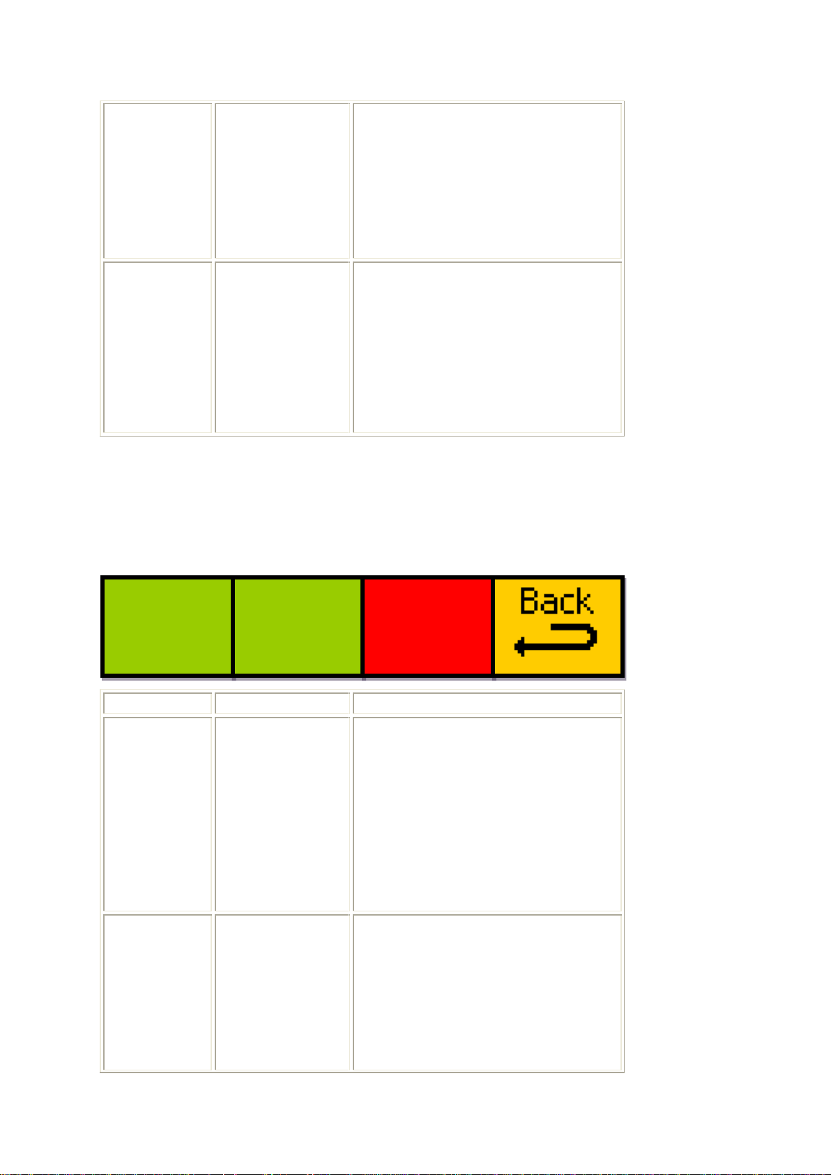
Eyeheight Limited, Sutton Business Centre, Restmor Way, Wallington, Surrey SM6 7AH
Reg. No. 2855535 Telephone: +44 (0) 208 255 2015 Fax: +44 (0) 208 241 6951 email: [email protected]
the „On Air‟ memory.
This will change the panel display
to „please wait‟, and will return
after a short delay to the ARC
Memory Select Top Menus (Go
To Menus 04-07)
203
Back
Pressing the button takes you to
the previous level of menus (Go
To Menus 100-103)
Pressing the prev button on the
panel will cycle to the previous
menu in the nested menu loop
(Go To Menus 196-199)
Menu Num.
Heading
Function
208
Cross-Fade
Transition Time
This menu sets the time in frames
that a transition between one
memory and another will take, the
minimum value of which is one
frame.
A detailed explanation of all
settings for these menus is given
in section 4.4.6
209
Fade to Black
Enable
This menu toggles the Fade to
Black transition option on and off.
If set to „on‟, cross-fading is
automatically disabled and will be
set to 1 frame.
If set to „off‟, the previously stored
X-fade
Time
=1 fr
Black
Fade
= off
FD=1
HD=1
FU=1
Menus 204-207
These menus are not usable by the user.
Menus 208-211 Transitions Menus
- 68 -
Page 69
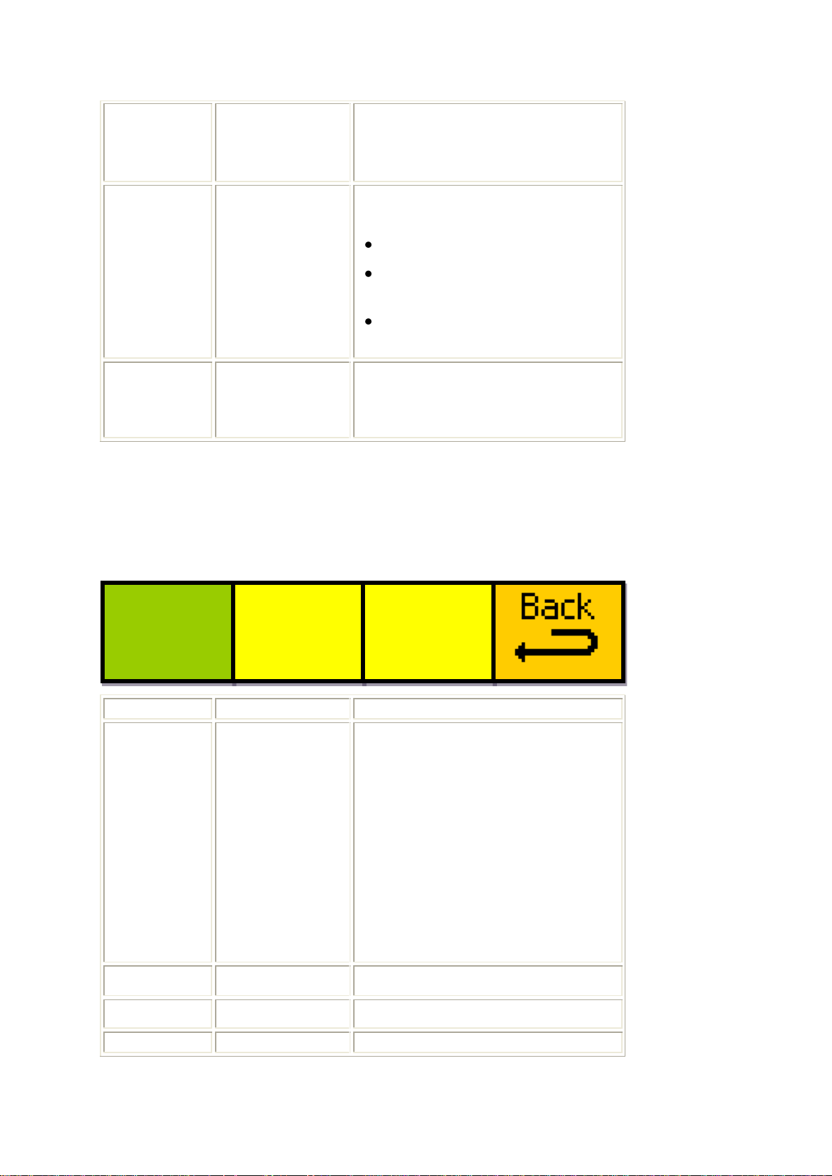
Eyeheight Limited, Sutton Business Centre, Restmor Way, Wallington, Surrey SM6 7AH
Reg. No. 2855535 Telephone: +44 (0) 208 255 2015 Fax: +44 (0) 208 241 6951 email: [email protected]
cross-fading value will be
restored and Fade to Black will
be disabled.
210
Fade To Black
Timing
Variables
This menu sets the profile of the
Fade to Black (if enabled).
FD sets the Fade Down time
HD sets the Hold Delay time
(the time spent in black)
FU sets the Fade Up time
211
Back
Pressing the button takes you to
the previous level of menus (Go
To Menus 140-143)
Menu Num.
Heading
Function
216
Film mode auto
detect
This sets the state of the film
mode detection software.
If set to on, the video processor
attempts to adapt to the video
being fed into the AR-2SD/MD.
This may give some unusual
artefacts in some circumstances,
but may improve the overall video
quality.
The default for this setting is off.
217
218
219
Back
Pressing the button takes you to
Auto
detect
= Off
Menus 212-215
These menus are not usable by the user.
Menus 216-219 Film mode detection
- 69 -
Page 70

Eyeheight Limited, Sutton Business Centre, Restmor Way, Wallington, Surrey SM6 7AH
Reg. No. 2855535 Telephone: +44 (0) 208 255 2015 Fax: +44 (0) 208 241 6951 email: [email protected]
the previous level of menus (Go
To Menus 136-139)
- 70 -
Page 71
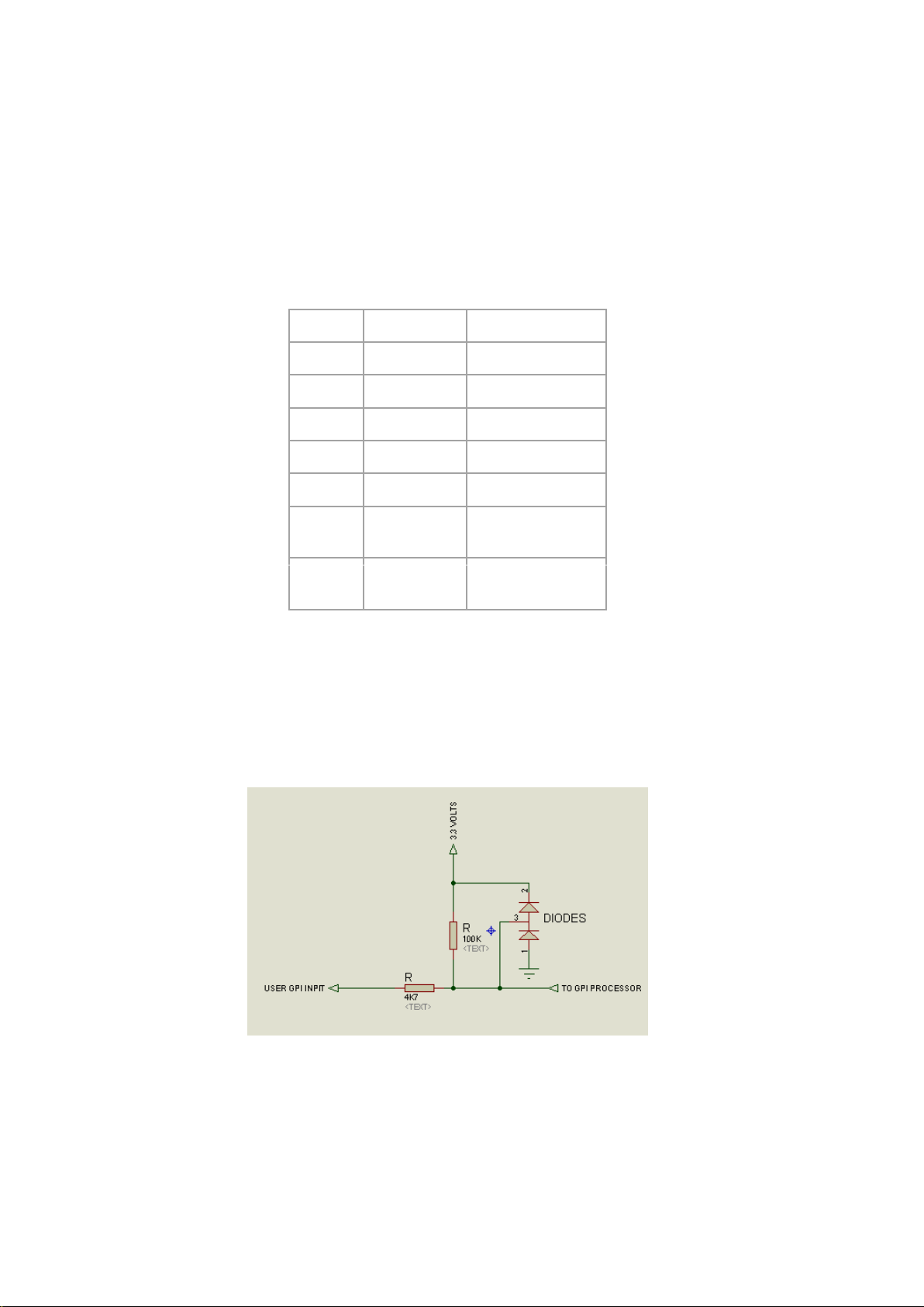
Eyeheight Limited, Sutton Business Centre, Restmor Way, Wallington, Surrey SM6 7AH
Reg. No. 2855535 Telephone: +44 (0) 208 255 2015 Fax: +44 (0) 208 241 6951 email: [email protected]
6 Technical Appendix
1
GPI-1
White/Orange
2
GPI-2
Orange
3
GPI-3
White/Green
4
GND
Blue
5
RS232 TX
White/Blue
6
RS232 RX
Green
7
Tally (open
collector)
White/Brown
8
GPI-4
Brown
6.1 GPI/Tally/RS232 technical information.
The AR-2N has an RJ-45 connector with GPI, Tally and RS232 connections as
shown below:
Table 1 GPI/Tally and RS232 pin-out on RJ-45.
Note that the Tally output is on a different pin compared to other genetics
products fitted with an RJ-45 connector.
6.1.1 GPI Inputs.
Figure 6-1 Typical GPI Input
GPI‟s are normally activated by a short to ground. The GPI has its own internal
pull-up resistor. If the user is interfacing with logic then
- 71 -
Page 72
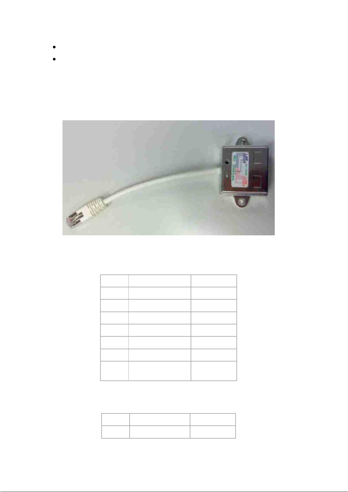
Eyeheight Limited, Sutton Business Centre, Restmor Way, Wallington, Surrey SM6 7AH
Reg. No. 2855535 Telephone: +44 (0) 208 255 2015 Fax: +44 (0) 208 241 6951 email: [email protected]
Vhigh = +12V>Vin>+3V
1
DO NOT CONNECT
White/Orange
2
DO NOT CONNECT
Orange
3
DO NOT CONNECT
White/Green
4
GND
Blue
5
RS232 TX
White/Blue
6
RS232 RX
Green
7
Not Used
White/Brown
8
Not Used
Brown
1
GPI-1
White/Orange
2
GPI-2
Orange
Vlow = +0.3V>Vin>0V
6.1.2 GPI Splitter
The soft panel comms and GPI connections are on the same RJ45 connector.
Eyeheight provide a GPI Splitter block which enables simultaneous use of the
RJ45 for the comms and the RJ45 for the GPI‟s. The Splitter has the following
pin-out which is also provided on a label on the splitter.
Figure 6-2 GPI Splitter. Has 2 RJ-45 Sockets, one for the Comms and one for the GPI's
Table 2 GPI Splitter, comms (Soft Panel) connection.
- 72 -
Page 73
Eyeheight Limited, Sutton Business Centre, Restmor Way, Wallington, Surrey SM6 7AH
Reg. No. 2855535 Telephone: +44 (0) 208 255 2015 Fax: +44 (0) 208 241 6951 email: [email protected]
3
GPI-3
White/Green
4
GND
Blue
5
GPI-4
White/Blue
6
DO NOT CONNECT
Green
7
Not Used
White/Brown
8
Not Used
Brown
Table 3 GPI Splitter, GPI connection.
SDI Inputs
(270 Mbps, 800mV p-p±10% into 75Ω)
1 Input to SMPTE 259M
SDI cable equalisation
At least 200m of PSF 1/3
Return loss better than 18dB, 5 MHz –
270 Mhz
HD-SDI Inputs
(1.845 Gbps, 800mV p-p±10% into
75Ω)
1 Input to SMPTE 292M
HD-SDI cable equalisation
At least 100m of Belden 1694A
Ancillary Data
Passes all ancillary data in vertical and
horizontal blanking except for CRC
recalculation.
Control Surfaces
Option of local or remote FP-9 control
panel.
Chassis
FB-9E etherBox 1U enclosure
THE CONNECTIONS LABELLED “DO NOT CONNECT” MUST BE
LEFT COMPLETELY UNCONNECTED.
6.2 Technical Specifications
When in SDI mode:
When in HD-SDI mode:
General:
- 73 -
Page 74

Eyeheight Limited, Sutton Business Centre, Restmor Way, Wallington, Surrey SM6 7AH
Reg. No. 2855535 Telephone: +44 (0) 208 255 2015 Fax: +44 (0) 208 241 6951 email: [email protected]
Supported Input Formats
SD
625
525
HD
1280x720/23.98p
1280x720/24p
1280x720/25p
1280x720/29.97p
1280x720/30p
1280x720/50p
1280x720/59.94p
1280x720/60p
1920x1080/23.98p
1920x1080/23.98psf
1920x1080/24p
1920x1080/24psf
1920x1080/25p
1920x1080/50i
1920x1080/29.97p
1920x1080/59.94i
1920x1080/30p
1920x1080/60i
Supported Output Formats
SD
625
525
HD
1280x720/23.98p
1280x720/24p
1280x720/25p
1280x720/29.97p
1280x720/30p
1280x720/50p
1280x720/59.94p
1280x720/60p
1920x1080/23.98p
1920x1080/24p
1920x1080/25p
1920x1080/50i
1920x1080/29.97p
1920x1080/59.94i
1920x1080/30p
1920x1080/60i
Delay
1 frame
Power Supply
100-240v AC. Less than 50W power
consumption with 6 AR-2 units
installed.
- 74 -
Page 75

Eyeheight Limited, Sutton Business Centre, Restmor Way, Wallington, Surrey SM6 7AH
Reg. No. 2855535 Telephone: +44 (0) 208 255 2015 Fax: +44 (0) 208 241 6951 email: [email protected]
FB-9E Dimension
Width 442mm
Height 44mm
Depth 300mm
Weight
<3Kg
Temperature
<25°C ambient, <55°C internal
Humidity
Recommended 40 to 55%
Limits 20 to 80%
6.3 Aspect Ratio Terminology
Recent developments in widescreen technology have made the use of Aspect
Ratio Converters Prolific. The industry as a whole has found it necessary to
formalise specifying the format of a picture on a 4:3 or 16:9 monitoring glass
using a sequence of letters and numbers. For example 16F16 is a normal Full
frame Widescreen picture viewed on a widescreen monitor.
Generally the format of the code is as follows:
PPAMM
“PP” is a number (usually 12,14 or 16) which describes the aspect ratio divided
by 9** of the “Viewable Picture” when viewed correctly (i.e not distorted). Note
this does not include any “Black” which goes to make parts of the picture that
have no picture content (e.g the black of the letterbox).
“A” is a letter describing the appearance of the “Viewable Picture” within the
Glass Screen. This can be:=
“F”, which means the picture completely fills the screen
“L”, which means the picture is letter-boxed. (Letter-box means there is a black
band at the top and the bottom of the picture).
“P”, which means the picture is pillar-boxed. (Pillar-box means that there is black
to the left and the right of the picture)
“MM” is a number (usually 12, 16) which describes the aspect ratio divided by
9** of the “Glass”.
(**Note that 16 therefore means 16:9, and 12 means 12:9, which is the same as
4:3.)
An example of a conversion is:
- 75 -
Page 76

Eyeheight Limited, Sutton Business Centre, Restmor Way, Wallington, Surrey SM6 7AH
Reg. No. 2855535 Telephone: +44 (0) 208 255 2015 Fax: +44 (0) 208 241 6951 email: [email protected]
16F1616L12
16F16
A Normal Widescreen (16:9) Picture.
12F12
A normal 4:3 Picture.
16L12
A 16:9 Letterbox viewed on a 4:3 (12:9) monitor.
14L12
A 14:9 Letterbox viewed on a 4:3 (12:9) monitor.
12P16
A 4:3 picture viewed on a 16:9 monitor leaving black to the left and
right. (Pillar-box)
14P16
A 14:9 picture viewed on a 16:9 monitor leaving black to the left and
right. (Pillar-box)
This means converting from:
“A picture that has a 16:9 appearance on a 16:9 monitor and completely fills the
screen”. (In other words a normal Widescreen picture)
To:
“A picture that has a 16:9 appearance on a 4:3 monitor and looks like a letterbox”.
Some Common Aspect Ratios
- 76 -
 Loading...