

Eyedro EHWEM1 Quick Start Manual
GREEN SOLUTIONS INC.
®
Eyedro
where electrified areas within the panel are.
DO NOT attempt installation unless you know
should be performed by a qualified electrician.
of shock, burn, and electrocution. Installation
panel may still be dangerous and carry the risk
at eyedro.com
Full warranty policy details are available
manufacturer, during this period.
repaired or replaced, at the discretion of the
workmanship. Defective parts may be
of purchase for all defects in material and
product for a period of one year from date
Eyedro Green Solutions Inc. warrants this
has been turned ‘OFF’ certain areas of the
are still electrified. Even when the main breaker
electrical panel to be removed while some wires
Installation may require the cover of the main
located at eyedro.com/support
and video can be found in the Product Manual
instructions. Complete installation instructions
This insert provides very high level installation
Limited One Year Warranty
Before Getting Started
®
Eyedro
Visit eyedro.com for any questions
or comments. We value your feedback.
GREEN SOLUTIONS INC.
Eyedro
GREEN SOLUTIONS INC.
®
Quick Start Guide
Wireless Electricity Monitoring System (EHWEM1)
For applications not exceeding
200A up to 300VAC
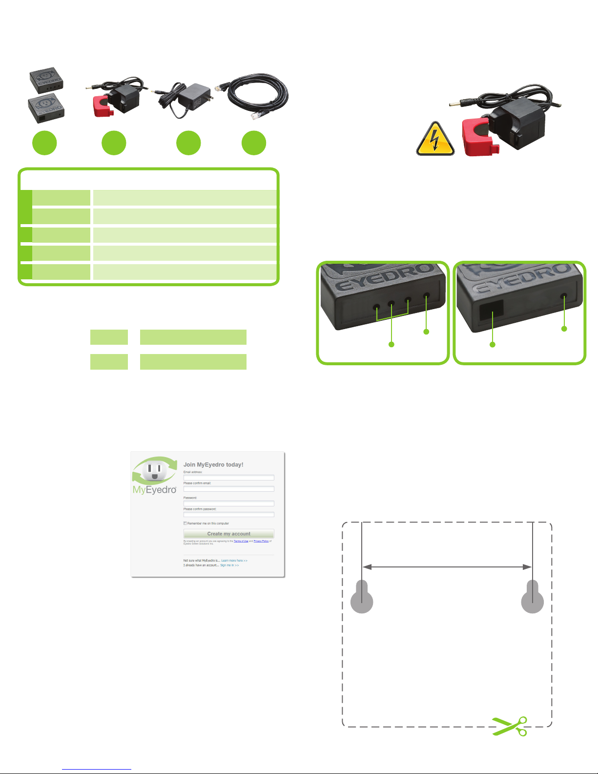
(2) (2) (2) (1)
A B C D
3. Install Hardware1. Verify Package Contents
3.1 Install Current Sensor(s)
on the line1 conductor
of the circuit(s) to
be monitored.
1
Line/Live/Hot conductor(s) only
QTY/LENGTH DESCRIPTION
A
B
C
D
1
1
2
2
3ft (0.9m)
Eyedro Gateway Module
Eyedro Sensor Module
200A Current Sensors (max 300VAC applications)
Low-voltage Power Adapter
Ethernet Cable
2. Record Serial Numbers
Gateway SN: -
Sensor SN: -
4. Create a MyEyedro User Account
4.1 GO ONLINE TO:
my.eyedro.com
to create your
online account
(or login if you
have an existing
account).
3.2 Securely mount the Eyedro modules,
using the template provided below (optional).
3.3 Connect Sensor(s) and
power adapter to the
Sensor module.
A
B
C
3.4 Connect Ethernet and
power adapter to the
Gateway module.
Power
Sensor(s)
Ethernet
Template for mounting the
Eyedro Modules (optional)
Cut out the below template and use it as a guide to
mark screw locations for a wall mounted module.
Power
4.2 Add the devices to your user account by entering the
serial numbers recorded earlier.
4.3 ENJOY! Login to MyEyedro as often as you like to
view your electricity consumption.
4.4 For more details regarding the MyEyedro service, review
the MyEyedro User Guide located at eyedro.com/support.
Copyright © 2016, Eyedro Green Solutions Inc.
2.36in (60mm)
 Loading...