


User Manual
for
VTracker &WitnessPro
Mobile Digital Video Recorder
Copyright 2013, Eye3Data
All Rights Reserved

2
Vtracker/WitnessPro-2.0
EYE3 WitnessPro/VTracker Digital Video Recorder
Contact Information
Eye3Data
9624 Cincinnati Columbus Rd.
Suite 310
Cincinnati, OH 45241 USA
Web site: www.eye3data.com
Local Phone: 513-779-0604; Local Fax: 513-898-0206
North American Sales: 888-777-9059 Email: sales@eye3data.com
Technical Support: 888-777-9059 Email: technical_support@eye3data.com
Customer Support 888-777-9059 Email: customer_service@eye3data.com
LEGAL NOTICE
Copyright ©2013 Eye3Data. All rights reserved. Eye3Data, EYE3, EYE3-Remote are registered
trademarks of MAI Media Group, LLC.
Acrobat is a registered trademark of Adobe Systems Incorporated.
Microsoft and Microsoft Windows registered trademarks of Microsoft Corporation.
The information contained in this guide is subject to change without notice. This manual was last
modified on January 11, 2013.
For your Records
Complete the following product purchase information. The factory requests this information
when contacted for technical support. It is also valuable in case of loss or theft.
Purchase Date: _______________________________________
Serial Number: ________________________________________
Thank you for using Eye3Data products. We support our products through an extensive dealer
network. The dealer through whom you originally purchased this product is your point of contact
if you need service or support. Our dealers are empowered to provide the very best in customer
service and support.
www.eye3data.com

3
Vtracker/WitnessPro-2.0
Contents
Product Overview .......................................................................................................... 5
Product Solution ........................................................................................................... 6
VTracker Connections .................................................................................................. 7
WitnessPro Connections .............................................................................................. 8
Handheld IR Remote Control ....................................................................................... 9
Menu Tree .................................................................................................................... 12
System Startup ............................................................................................................ 13
Menu Configuration .................................................................................................... 14
I.Search ........................................................................................................................ 15
1.0 All Files .................................................................................................................... 15
1.1 Event Files .............................................................................................................. 18
II.Setup ......................................................................................................................... 20
2.0 System ..................................................................................................................... 20
2.1 Date/Time ................................................................................................................ 20
2.2 General .................................................................................................................... 21
2.3 Register Info ........................................................................................................... 24
2.4 Format ..................................................................................................................... 25
2.5 Upgrade ................................................................................................................... 25
2.6 User Security .......................................................................................................... 27
2.7 Configuration Files ................................................................................................ 28
2.8 System Log ............................................................................................................. 29
2.9 GEO-Fencing .......................................................................................................... 29
3.0 Record ..................................................................................................................... 30
3.1 Option ...................................................................................................................... 30
3.2 OSD (On Screen Display) Overlay ....................................................................... 32
3.3 Channel Setting ...................................................................................................... 33
3.4 Record Setting ....................................................................................................... 34
3.5 Sub-Stream ............................................................................................................. 35
3.6 Schedule ................................................................................................................. 36
3.7 Other Set ................................................................................................................. 37
4.0 Network ................................................................................................................... 39
4.1 Server Network ....................................................................................................... 39
4.2 Local Network ........................................................................................................ 40
www.eye3data.com

4
Vtracker/WitnessPro-2.0
4.3 WIFI Setup ............................................................................................................... 40
4.4 Mobile Network ...................................................................................................... 41
5.0 Event ........................................................................................................................ 44
5.1 Sensor ..................................................................................................................... 44
5.2 Sensor Output ........................................................................................................ 45
5.3 Speed ....................................................................................................................... 46
5.4 Acceleration ............................................................................................................ 47
5.5 Temperature ........................................................................................................... 48
5.6 Camera .................................................................................................................... 48
5.7 Voltage .................................................................................................................... 49
6.0 Peripheral ................................................................................................................ 50
6.1 PTZ ........................................................................................................................... 51
6.2 EXT.COM Setup ...................................................................................................... 51
III.Information .............................................................................................................. 52
7.0 System ..................................................................................................................... 52
7.1 History ..................................................................................................................... 53
7.2 Modules ................................................................................................................... 53
www.eye3data.com

5
Vtracker/WitnessPro-2.0
Product Overview
WitnessPro/VTracker is a cost-effective and well-designed HDD/SD card based Mobile Digital Video Recorder
specially designed for vehicle surveillance and remote monitoring and combined with a high-speed processor and
embedded operating system. The advanced H.264 video compression and decompression, wireless transmission,
and GPS location make WitnessPro/VTracker a very powerful and perfect solution for vehicles.
WITNESSPRO/VTRACKER VIDEO AND AUDIO FEATURES AND CAPABILITIES
Four channels for video input capable of 30 fps per channel on CIF and 12fps/15fps per channel on D1 with
continuous or priority video recording and live view display.
Semi-transparent GUI allows setting for GUI and live display simultaneously.
Proprietary file system NVRFSTM which allows for the security of data, self-recovery, self-check, self-backup for
certain critical data and avoidance of data fragments that can affect system efficiency.
Mirror recording feature records additional video simultaneously for up to 8 hours on internal SD card in case
HDD is damaged or not accessible for recording data. (This option only applies to the WitnessPro model)
Watermark which prevents any modification of a recorded file, (most law enforcement agencies require this
feature).
Dual-Stream for wireless transmission for wide or narrow bandwidth.
Better compression rate at H.264 (50% less than MPEG4) which enhances the recording storage rate in the
most efficient way.
Each video channel is synchronized with audio.
User friendly criteria to playback events.
Automatic timer to resume the live display if the unit is idle.
User-selectable settings for quality and audio record enable/disable for each video channel.
12VDC output power for multiple devices such as cameras, sensors, relays and any other accessories.
Selectable frame rate with event-triggered burst recording speeds up to 30FPS/camera.
Multiple alarm inputs with selectable pre-alarm and post-alarm recording times.
REMOTE CONNECTION CAPABILITIES
Handheld infra-red controller with OSD for quick access to recorded video and settings menu.
Eye3 Evidence - PC-Based client software for live viewing, playing back video, and playing back events
associated with video and downloading capabilities.
Eye3Dispatch Live View - for remote monitoring via CDMA/GPRS/EDGE/3G/4G and WIFI.
www.eye3data.com
6
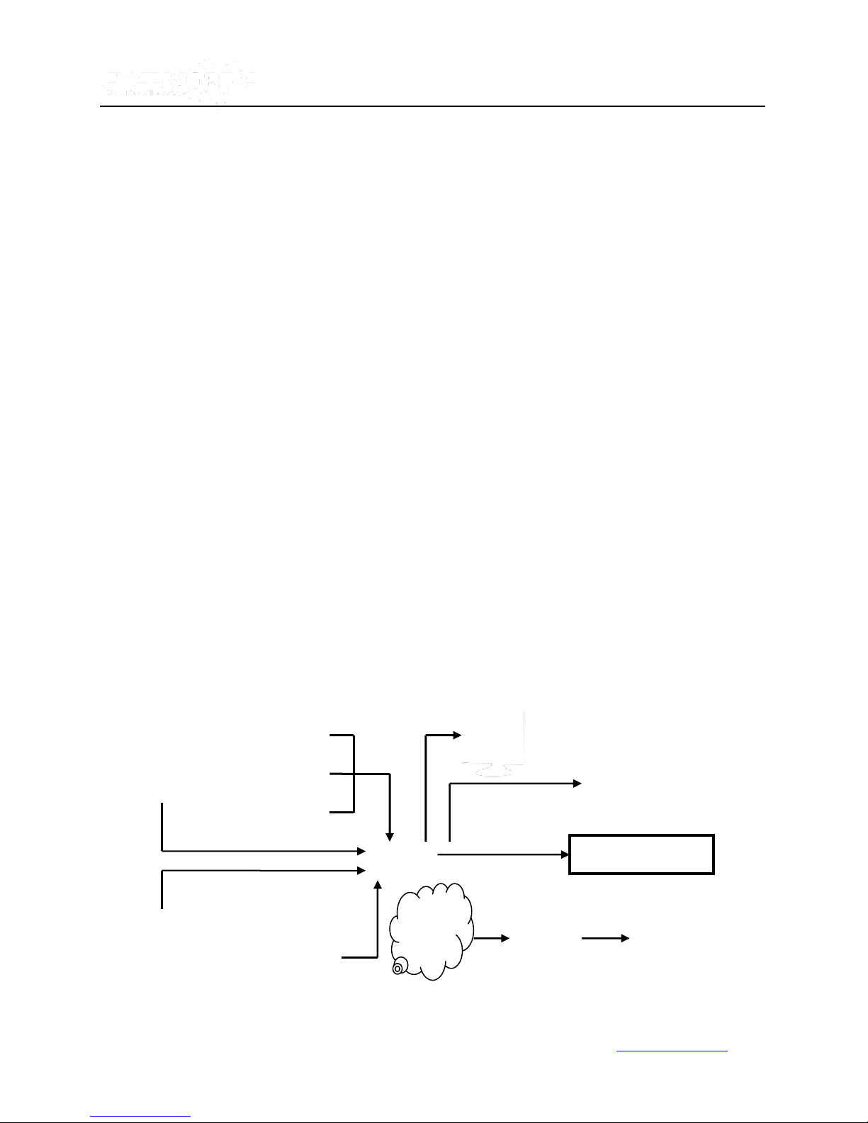
Passenger statistic
IR
Control
CMS client
Playback
GPRS
CDMA
EDGE
Wireless
Camer
Live
Vtracker/WitnessPro-2.0
ACCESSORY MODULES
Video interface module includes GPS location and speed.
Vehicle motion manager includes 3-axis Inertia Sensor to determine video-matched motion events.
Wireless module CDMA/GPRS/EDGE/3G, WIFI for transferring data to Eye3Dispatch Live View server for
remote monitoring.
Product Solution
1. Live View:
Can check the live view, GPS location, and alarm information from the WITNESSPRO which is
transferred by a wireless network CDMA/GPRS/EDGE/3G.
Announcements of stations automatically based on GPS information. (Not Available in this release)
Vehicles can send status information to the CMS via wireless transmission. The CMS can also send
commands to the vehicle.
2. Retrieving Video Data:
Copy records file via USB or removable HDD case.
Analyze records files via playback software.
Support LAN for auto download.
www.eye3data.com

7
VTracker Connections
Vtracker/WitnessPro-2.0
www.eye3data.com

8
Items
Name
Description
WI-FI ANT connector
WI-FI
For connecting the WIFI ANT
GPS ANT connector
GPS
For connecting the GPS ANT
3G/EDGE/GPRS Con
3G
For connecting the 3G/EDGE/GPRS ANT
Power input
DC8-48V
For connecting power input
Network port
RJ45
Network port to make sure the MDVR can go online
A/V Integrated input
A/V
A/V input and output and alarm output
Power supply for camera
I/O Input and Output
I/O
I/O sensor input and output
EXTEND Interface
EXTEND
For extend function, such as RS485 and RS232
serials port.
WitnessPro Connections
Vtracker/WitnessPro-2.0
www.eye3data.com

9
Numeric
Input Keys
Use the numbers to input
values in the system to setup
screen or switch through the channels in live view
and playback. The plus and minus keys
are used to increase setup values one by one.
Navigation
Arrows
Use the ARROW keys to move between
selections (input fields and icons).
Press ENTER to select
and EXIT to return. NEXT and PREVIOUS are
also used to increase or decrease volume when in
live view or searching footage.
Handheld IR Remote Control
Vtracker/WitnessPro-2.0
Each WITNESSPRO includes a handheld infra-red (IR) controller that allows the user to operate the
screen control menu.
www.eye3data.com

10
LOGIN/ LOCK
Use LOGIN / LOCK or SETUP key to enter the user setup. If the
security/password is enabled in the setup, you will have to enter the
default Admin password: 88888888.
POWER
The Power button can force the WITNESSPRO into a sleep mode.
Note: the unit will stop recording while in sleep mode.
Swap between multi-channel and single channel monitor while in the
surveillance screen only. Press this button to change the number of
display channels. By pressing this key, display channels change in
the sequence of four→ one→ two→ three→ four→one.
Adjust the brightness, contrast, and color adjustment. Use [+] [-]
button to change the values. User can adjust the values for each
channel individually.
SETUP
System setup (may require login).
EXIT
Return to the previous menu. Pressing the EXIT key goes to the
previous screen until the live view screen is displayed.
Stop
Stop the recording manually.
Handheld Control Key Functions:
1. Numeric Keypad:
[0-9] keys: During setup, the number keys are used to input values.
For toggling between channels, use the numeric keypad to access the corresponding camera.
[+], [-] keys: During setup, the plus and minus keys are used to select next or previous values.
For example, pressing will navigate through the color adjustment options during the real
time view of an individual camera. After you pressed key, you can use the plus and
minus key to make the color adjustments. Please be advised that the unit needs to stop
recording before any color adjustments are made.
2. Setup Menu Navigation:
▲, ▼: Up, down directional keys: Moves the selection up and down in the setup menu.
►, ◄: Left, Right directional keys: Moves the selection left or right in setup menu.
[ENTER] key: During setup, the ENTER key allows to select and save entry
During playback, the ENTER key displays all the set up information in the
OSD overlay menu.
3. Other Key Functions:
Vtracker/WitnessPro-2.0
www.eye3data.com

11
Batteries are not included in the standard package.
Record
Start the recording manually.
PAUSE/STEP
▐►
Freeze playback to a single frame and advance one frame at a time.
To advance the frame, press Pause / Step to move frame by frame.
Press EXIT to return to normal playback speed.
PLAY ►
Starts/Resumes playback from any other mode (FF, RR, Frame by
Frame etc).
SLOW
Reduce playback speeds to 1/2, 1/4, 1/8 modes. Press PLAY to
return to normal playback speed.
GOTO
Quick search mode within the playback file. Select the file and Press
start to play. Press GOTO button and input the user defined time.
Select START to jump to the specific time.
NEXT
Increase volume while playing back recorded footage (if audio is
recorded) or multimedia.
PREV
Decrease volume while playing back recorded footage (if audio is
recorded) or multimedia.
REW
Rewind the video during playback. 2X and 4X modes are available.
FWD
Fast forward the video during playback. 2X and 4X modes are
available.
[F1]
Exports all the event record files of the day to a USB
[F2],[F3],[F4]
Reserved for future use
[ZOOM IN +], [ZOOM OUT -]
Zooms in and out
[IRIS +], [IRIS-]
Controls brightness
[FOCUS +], [FOCUS -]
Focuses in and out
PTZ
Activate the PTZ function
AUTO
Auto run with the PTZ pattern
PRESET
Presets default position
RECALL
Recalls the previous program
BRUSH
Brushes the glass screen
Vtracker/WitnessPro-2.0
4. PAN/TILT/ZOOM Functions
If connected with PTZ cameras, the following commands can be used to control the PTZ camera:
www.eye3data.com

12
Menu Tree
Vtracker/WitnessPro-2.0
www.eye3data.com

13
WitnessPro/VTracker menu is semi-transparent; you can see the live view when you make GUI configurations.
Vtracker/WitnessPro-2.0
System Startup
After connecting the WitnessPro or VTracker to the vehicle power supply (refer to the installation diagram),
turn on the vehicle ignition and the unit will automatically start recording.
Login screen for System Setup
www.eye3data.com

14
User default password is 22222222 and Admin default password is 88888888.
OPERATOR Password allows user to access limited video and sensor menu items.
ADMIN Password allows user full access to the MDVR.
SUPER Password allows user full access to the MDVR under the circumstance of losing the ADMIN password.
PLEASE NOTE: Press SAVE to enable all changes. The system will give a notification when changes are saved
successfully. Any modifications that are made to the network will automatically restart the system after you exit the
SETUP. The MDVR will automatically stop recording when the user enters the MDVR configuration. You can input
the letters and characters by software keyboard.
Vtracker/WitnessPro-2.0
• When the password is disabled, press the SETUP key on the remote to access
the setup menu directly.
• When Password is enabled, press the LOGIN/LOCK OR ENTER key on the remote and enter the user
name and password to access the setup menu.
UNIT ID: The ID of the WitnessPro/VTracker. You can change the ID setting in the GUI. After the ID has been
set, the number will be displayed automatically in parenthesis [i.e. (123456)].
PASSWORD: Enter the admin password or user password.
Keyboard: Press【Enter】to use keyboard to type device ID and password.
1)0~9, number key, press【Enter】to select the number.
2)123: Input type shift key. (Number, capital, small letter)
3)【←】delete, 【 】Exit.
Menu Configuration
This section will show all the main functions of the WitnessPro/VTracker menu which includes SEARCH, SETUP and
INFORMATION. SEARCH is used for searching all the video files and alarm files, SETUP is used for configurations
and INFORMATION is used to display unit status.
www.eye3data.com

15
FILE SOURCE:
User can choose to playback from the HDD/SD or from the SD for mirror
recording in WitnessPro/VTracker.
I. Search
Vtracker/WitnessPro-2.0
1.0 All Files
You can search all the video files including normal files and alarm files by record time and file type. By selecting
the option ALL FILES, the following screen will display:
www.eye3data.com

16
FILE TYPE:
The type of file: alarm file or normal file.
DATE:
WitnessPro/VTracker system will display the current day automatically. Any day
with recorded files will be indicated in green. Any day with ALARM FILES will be
indicated in red.
START TIME:
The default setting is 00:00:00. This indicates the recording start time.
END TIME:
The default setting is 23:59:59. This indicates the recording end time.
This feature allows the user to search from a specific time. For example: If the
date is 2010-04-14 and the time is 00:00:00, it indicates that you want to search
the entire video file from 00:00:00 to 23:59:59 on April 14, 2010. If the date is
2010-05-16 and the time is 12:25:00, then it indicates that you want to search all
the files from 12:25:00 to 23:59:00 on May 16, 2010.
SEL:
This section allows for selecting files for backup. Press the arrow key on the remote control to
select the box next to the file for back up. A [×] will display in the box.
REV.:
Press REV for selecting all or no files. For example, if you do not select any file for backup and
press 【REV.】, all the files will automatically be selected. However, if you select one file and
then press 【REV.】, all of the other files are now selected, but the file originally selected before
is now automatically unselected.
LOCK:
L means this file is locked. U Means this file is unlocked. Lock means the alarm file is
protected for the configured days to avoid being overwritten. To enable or disable the lock
function, go to SETUP--EVENT in the setting interface. This can be done for any type of alarm.
Vtracker/WitnessPro-2.0
NOTE: Green color indicates normal record files. Red color indicates alarm record files
Press【SEARCH】to enter into the next menu for listings of all video files sorted by the file type, date
and time.
www.eye3data.com

17
If the external storage device is not connected or is defective, then the system will display “NO THUMB
DRIVE.”
Please activate the locked files in the EVENT menu. Only EVENT files can be locked since most event files are very
important. If the video file is locked, then the file cannot be deleted by HDD overwrite function. Files can be deleted
by the HDD overwrite function, only when the files are unlocked and the lock save time is invalidated. Locked files can
be deleted only with the HDD format function.
Vtracker/WitnessPro-2.0
EXPORT: Export the selected file to external device by USB port on the front of the WitnessPro/VTracker.
To export events to the storage device, connect the external storage device to the WitnessPro/VTracker by USB port
and then press【EXPORT】The following screen will pop up:
TOTAL: The number of files that are selected for back up.
No.: The current file number that is in the process of backing up. After successful backup, the following screen will pop
up:
www.eye3data.com

18
FILE TYPE:
The type of EVENT file including I/O ALARM/ACCELERATION/SPEED/TEMP
ALARM/VL ALARM/MOTION DETECTION/BLIND, etc...
DATE:
The WitnessPro/VTracker system will display the current date automatically. The
dates with event recorded files will be indicated in red.
Vtracker/WitnessPro-2.0
If the system’s current video type is different from the last video type recorded, then the system cannot play back the
video. (Note: the default video format is NTSC.)
For example: If a video file was recorded and created when the system was set in PAL format, then the video file
cannot be played back when the WitnessPro/VTracker is rebooted up in NTSC format. The system has to be set in
the same format type as the video file was recorded or created in. If not, then the following screen will pop up:
Please enter SETUP-> RECORD-> OPTIONS-> and change the video type to PAL to view the video in the format it
was recorded in. Also, if the HDD files are recorded on an 8 channel WitnessPro previously, then the video files
cannot be played back on a 4 channel UNIT.
1.1 Event Files
The EVENT SEARCH searches the entire Event file LOGS instead of individual video
files.
www.eye3data.com

19
PLEASE NOTE: The event list is only to search and back up logs of event files (such as event name, start time, date
occurred), not video files. If you want to view the event (alarm) videos, search the ALL FILES menu option.
SEL:
For selecting the LOG file you want to backup. Use the arrow keys on the remote
control to select the log file that you want to back up. A [×] mark will display in the
box of the LOG that you selected for backup.
Pressing 【REV.】 will select or deselect all the files for backup.
EVENT NAME:
The event name indicates the type of event such as video loss, over speed, low
speed, high temperature, sensors and so on.
DATE:
The date when the event occurred.
TIME:
The start time when the event occurred.
REV.:
To select or deselect all files. For example, if you did not select any file(s) for
backup, then by pressing【REV.】, all the files will be selected.
EX LOG:
Export the selected LOG file to an external device by USB port on the front of
UNIT.
EXPORT:
Export the related video if the event has the record file. If no related video file, you
will get a message that no video file found.
Vtracker/WitnessPro-2.0
Press【SEARCH】to display the EVENT LIST MENU. The menu lists all the video files according to file type and
date.
www.eye3data.com

20
Vtracker/WitnessPro-2.0
II. Setup
This section explains how to setup the unit and how to check the working status.
2.0 System
Use ARROWS to select and press ENTER. The screen will show the menu as below:
2.1 Date/Time
www.eye3data.com

21
DATE FORMAT:
(US or International):
Press 【ENTER】to select format desired: MM/DD/YYYY,
DD/MM/YYYY, or YYYY-MM-DD.
TIME FORMAT:
Press【ENTER】to select the time format desired: 12H or 24H.
TIME SYNC SOURCE:
The system will allow the time to be synchronized via “GPS” or “NTP”.
GPS option
If selecting the “GPS” option, the device must have a GPS connection
and a good GPS signal.
NTP option
If selecting the “NTP” (Network Time Protocol) option, the device
must have a network access connection and an assigned NTP IP
location. This process runs at 6:30am local time when the system has
a network connection.
TIME ZONE:
Please choose the correct time zone for the vehicle location. This is
the time zone in which the vehicle is located.
SYNC TIME:
This is the time when the unit will sync with the server every day. This
method depends on the setting in the TIME SYNC SOURCE option.
NTP SERVER IP:
In order to use the NTP feature, please enter the IP address to the
NTP server. [Example: "192.43.244.18", "129.6.15.28",
"211.22.55.116", "194.88.2.60"]
DST:
Daylight Savings Time. The following option is available, only when
it is set to ON.
DST MODE:
There are two modes: Auto / Manual. Auto: According to the
International DST, i.e.: valid only between 2AM on Second Sun in
March and 2AM on First Sun in NOV.
When setting the DST, the former date must be earlier than the later date; otherwise, if the two setting dates are the
same, the DST will be invalid.
Vtracker/WitnessPro-2.0
Select【SAVE】to save the settings.
2.2 General
ON/OFF TYPE: There are three options: IGNITION, TIMER and IGNITION OR TIMER
A) IGNITION: This function allows for a shut down delay. For example: If you set the shut down delay
function time at five minutes, then every time the ignition is turned off the WitnessPro/VTracker will shut
down after five minutes.
www.eye3data.com

22
Vtracker/WitnessPro-2.0
B) TIMER: This function allows you to set an automatic recording timer. If you select TIMER, then the
following screen below will pop up. This will allow you to set up your BOOT UP TIME and SHUT DOWN
TIME.
C) IGNITON OR TIMER: This function allows both conditions.
www.eye3data.com

23
BOOT UP TIME:
The exact time unit starts every day.
SHUT DOWN TIME:
The exact time unit shuts down every day.
BOOT UP IN
RECORDING TIME:
Record Function linked to Timer Start Up. For example, if ON is enabled and
the BOOT UP TIME is set to 6:00:00, then at 6:00:00, the unit will automatically
start to record even if the ignition is OFF.
BUZZER SWITCH:
When this feature is set to ON it allows for the buzzer to sound when an alarm is
triggered. When set to OFF no buzzer will sound when an alarm is triggered.
The buzzer sound time depends upon ALARM time set in the
SETUP-RECORD-OPTION.
IDLE TIME (SEC):
The time set to switch back to live view when there is no activity by the User.
For example, if the IDLE TIME is set at 300 seconds, then the system will switch
back to live view automatically after 300 seconds of no activity.
EVENT FILES AUTO
EXPORT (USB):
When set to ON, the system will back up all the alarm record files of the day by
pressing the F1 key on the IR control in Live View Mode.
ASPECT RATIO:
This function allows you to set up the OUTPUT MODE. There are two OUTPUT
MODE options 4:3 and 9:6. Select the option you want.
TRANSPARENCY:
This function allows you to set up the brightness for the screen display.
Note: if the boot up mode is set to TIMER and the unit is manually rebooted outside the boot up and shut down time,
then the unit will only be powered on for five minutes before shutting down again.
Vtracker/WitnessPro-2.0
Select【SAVE】to save changes.
www.eye3data.com

24
UNIT S/N:
The Serial Number for WitnessPro/VTracker. Every unit has only one
Serial Number. This number is read from a special encrypted chip.
UNIT ID:
Is the Device ID. Use the NUMERIC keypad to enter the system ID from
00000 to 99999. This ID is used when logging into the unit.
COMPANY NAME:
The name of company or organization.
VEHICLE NO:
The number of the vehicle.
DRIVER/ROUTE NAME:
The driver’s name and/or the route name.
DEVICE ID:
ID used to connect to Eye3Dispatch Live View. This ID is unique and is
very important for the Eye3Dispatch Live View. Only this number can be
recognized by the Eye3Dispatch Live View.
NOTE: when you connect the unit to Eye3Dispatch Live View, make sure
the VEHICLE NO. and DEVICE ID are not blank; otherwise, the unit will
not connect with the server.
2.3 Register Info
Vtracker/WitnessPro-2.0
Select【SAVE】to save all changes.
www.eye3data.com

25
DEVICE:
Press 【ENTER】 to select the target device for format. There are 2
options: VIDEO STORAGE (HDD) and/or SD/ USB. Press 【FORMAT】to
format the storage device.
FUNCTION:
Area where you choose what type of formatting you want. There are 3
options: FAST FORMAT, SLOW FORMAT, DETECT VIDEO
STORAGE.
Vtracker/WitnessPro-2.0
2.4 Format
Select the device you want to format: Video Storage, SD card, or external USB storage device.
After the format is successful, the system will restart automatically.
2.5 Upgrade
Upgrade to new FIRMWARE or MCU (Machine Code Unit).
www.eye3data.com

26
DO NOT REMOVE THE POWER OR REMOVE THUMB DRIVE FROM THE UNIT DURING FIRMWARE
UPGRADE. Doing so can permanently render the unit inoperable. Please check the FIRMWARE version
after the unit reboots and make sure that the FIRMWARE upgrade is successful.
FIRMWARE:
Upgrade the FIRMWARE.
MCU:
Upgrade the MCU.
HOW TO UPGRADE THE FIRMWARE:
1. On a thumb drive, create a folder named dvrupgrade and copy the FIRMWARE upgrade file to this
folder.
2. Insert the thumb drive into the USB port on the front panel of the WITNESSPRO/VTracker.
3. Go to SETUP-> SYSTEM-> UPGRADE and press 【UPGRADE】to begin the firmware upgrade.
4. During the FIRMWARE upgrade, the following screen will pop up:
Vtracker/WitnessPro-2.0
5. After upgrade is successful, the system will restart automatically as follows:
If the firmware of the unit is current, then you cannot upgrade the firmware again. The following screen
www.eye3data.com

27
The default password for Admin is 88888888.
PASSWORD ENABLE:
Selecting “ON” will require a password to access the setup menu.
Selecting “OFF” will not require a password to access the setup
menu.
USER PASSWORD:
User can only use the search feature. Any other parameters
cannot be modified.
ADMIN PASSWORD:
Administrators have full rights.
will pop up if you try upgrading the firmware again:
2.6 User Security
Set up password for USER and ADMIN.
Vtracker/WitnessPro-2.0
www.eye3data.com

28
EXPORT:
This feature allows you to export all the configurations of your unit to another
unit to make configuring multiple systems easier. Please insert the external
storage device to the USB port and press【EXPORT】. The configuration file
will export to the external device.
IMPORT:
This feature allows you to import the unit configuration files from a USB thumb
drive. Insert the thumb drive with the configuration into the USB port and
press 【IMPORT】. The configuration will import to unit automatically.
Vtracker/WitnessPro-2.0
CONFIRM: Re-enter the PASSWORD. If the password does not match, the system will not accept the password
setting. The following screen will pop up:
After the password is set, select【SAVE】to save the changes.
2.7 Configuration Files
Restores default settings and exports/imports the unit configuration.
www.eye3data.com

29
RESTORE:
Restores the default settings.
EXPORT THE GEO
FENCING CONFIG
FILE:
Export all the GEO-FENCING configuration files from one
EYE3WITNESSPRO/VTRACKER to another. This confirms that both
systems have the same settings. To export the GEO-FENCING configuration
file, insert the external storage device to the USB port and press【EXPORT】.
Vtracker/WitnessPro-2.0
2.8 System Log
Exports or Deletes the SYSTEM LOG. As shown below:
NOTE: SYSTEM LOG contains: Start record time, event time, stop record time, power on / power off time, etc.
2.9 GEO-Fencing
Exports or Imports the GEO-FENCING Configuration File.
www.eye3data.com

30
The configuration file will export to the external device.
IMPORT THE GEO
FENCING CONFIG
FILE:
Imports the EYE3WITNESSPRO/VTRACKER GEO-FENCING configuration
files to the current device. Insert the external storage device to the USB
port (Must have configuration file in the storage device) and then press
【 IMPORT 】 . The configuration file will be imported to the system
automatically.
3.0 Record
Set up the related configuration for Record
Vtracker/WitnessPro-2.0
3.1 Options
Setup the basic parameters.
www.eye3data.com

31
VIDEO TYPE:
There are 2 options: PAL and NTSC. The default setting is NTSC.
RECORD MODE:
There are three modes: GENERAL, TIMER, and EVENT:
GENERAL:
Unit will start to record automatically when powered up and the key is in the locked
position.
TIMER:
Unit will start to record at a defined time based on the schedule set in the
SETUP--RECORD-SCHEDULE
EVENT:
Unit will start to record and create an event record, when an event is triggered.
NORMAL REC RATE:
There are two options: NORMAL and I FRAME:
NORMAL:
Unit will start to record according to the parameters set in the RECORD SETTINGS.
I FRAME:
Unit will only record at one frame per second to use less space on the hard drive.
When an event is trigged, the unit will record according to the parameters set in the
RECORD SETTINGS.
ALARM PRE-REC TIME
(1-60)MIN:
This feature allows s users to setup a pre-record time based on Events.
For instance, if the pre-record time is set for 30min. and then when an alarm is
triggered, the event file will show all recording 30 min. before and up to when the
alarm was triggered. For example, if an alarm was triggered at 10:30 am, a
record file will be created starting from 10:00am to 10:30 am. The system will
consider the record file as one alarm event.
ALARM DURATION
(3-30)SEC:
The time set up in this feature sorts all the alarms of the same type to be considered
one alarm during the alarm duration unit resets the duration time automatically).
For example, if the setting of the alarm duration is ten seconds and during these ten
seconds a similar alarm is triggered, then the system will consider them to be one
alarm event. Also the alarm start time will be reset based on the second time for an
alarm.
ALARM POST REC
(30-1800)SEC:
The alarm post record time setting sets the length of the recording.
BUZZER ALARM TIME:
Set up buzzer Alarm duration time. When an alarm is triggered, the buzzer alarm
will go off for the pre-defined duration time.
Vtracker/WitnessPro-2.0
www.eye3data.com

32
METADATA CAPTURE:
If METADATA is set to ON, it will capture the GPS, sensor information, speed,
and event log.
RECORD FILE TIME(MIN):
This option sets the recording file times: 15, 30, 45, 60 minutes.
HDD/SD OVERWRITE:
The HDD will overwrite or stop recording when there is less than 2GB space left
on the HDD.
ON: According to “first in first out” rule, when hard drive space is less than
2GB, the system will start to delete the earliest recorded files until the disk space
is equal to or over 10GB (except for the alarm files which are locked).
OFF: The device will stop recording when there is no more disk space (less than
500M). You must replace the HDD or delete the recorded files manually until the
HDD space is equal to or over 10GB. It will then start to record again.
LOCKED FILE RETENTION
(DAY):
Locked recorded file save time: 7, 10, 15, 20, 30, 45 days.
The save time ensures that the locked recorded files will not be deleted. Once
the lock time passes, the recorded files with the LOCK (L) identifier will change
from locked to unlocked (U). The recorded files can now be deleted.
PRE-RECORDING SWTICH
ON/OFF – Needs to be set to "ON" for the pre-recording time to be valid.
SD CARD TYPE
INTERNAL: For mirror recording on WitnessPro. Does not apply to the
VTracker unit.
MIRROR REC.TO SD CARD:
For WitnessPro unit only - Activates the Mirror function. The SD card and HDD
can record at the same time. The HDD will record on a high resolution, but the
SD card will record on lower resolution. The mirror function is intended for
backup. If the HDD is damaged, you can search the video files from SD card.
DATE/TIME:
Displays date and time on the OSD.
ALARM:
Displays Alarm information on the OSD.
ACCELERATION DATA:
Displays the information for the inertial sensor.
Vtracker/WitnessPro-2.0
3.2 OSD (On Screen Display) Overlay
Set up the screen which controls the options to be viewed on the WitnessPro/VTracker OSD in live view.
www.eye3data.com

33
TEMPERATURE:
Displays the temperature on the OSD.
FIRMWARE VERSION:
Displays the current firmware version.
GPS INFO:
Displays the GPS working status.
CH NAME:
Displays Channel name
VEHICLE NO.:
Display Vehicle ID
IMAGE:
Transparent image toggle switch to turn ON/OFF
POSITION:
Display s Overlay text position Top/Bottom
If all the options are ON, Then the following screen will pop up after you press
【Enter】during live view. During live view, press 【Enter】 on remote control to view
the unit working status.
Vtracker/WitnessPro-2.0
3.3 Channel Setting
Set up recording options for each channel.
www.eye3data.com

34
EN:
Enables record function.
NAME:
Set a name for the channel. In this section, you can define a name for each
channel. For example, if you set up the name “ABC” for channel 1, then
when you are in live view, you Channel 1 will be as “ABC”.
AUDIO:
The audio record function. ON: activates the audio record function. OFF:
Disables it.
LIVE:
Live view.
ON: Displays cameras in live view.
OFF: Hides cameras in live view.
ROUND:
The channel loop function displays each channel in full screen on a rotating
basis.
ROUND TIME:
Time designated to view channel as full screen.
RES: Resolution options: D1, HD1, and CIF.
D1 resolution: 704×576
HD1 resolution: 704×288
CIF resolution: 354×288
FR: Frame Rate. Frames recorded per second, can be set anywhere from 1 to 25.
NORMAL QUALITY: Image quality for a normal recording. Levels 1-8; Level 1 is the best.
ALARM QUALITY: Image quality for an alarm recording. Levels 1-8; Level 1 is the best.
Vtracker/WitnessPro-2.0
3.4 Record Setting
Set configurations for RESOLUTION, FRAME RATE (FR), IMAGE, and NORMAL QUALITY, ALARM
QUALITY parameters for each channel.
www.eye3data.com

35
EN: Enables or Disables the channel.
RES: Resolution, CIF and QCIF option.
FR: Frame rate set from 1 to 25.
QUALITY: 1=high and 8=low
BIT: User defined, based on your bandwidth connection.
3.5 Sub-Stream
SUB-STREAM is the video settings for the Eye3Dispatch Live View transmission.
There are two MODES for SUB-STREAM:
MODE 1 is for a wider bandwidth network such as LAN or WIFI.
MODE 2 is for a narrower bandwidth network such as a mobile wireless transmission.
Vtracker/WitnessPro-2.0
When you select MODE1, and then press SURE, the following interface screen pops up:
When you selected MODE2 and then press SURE, the following interface screen pops up:
www.eye3data.com

36
BANDWIDTH:
Set up the bandwidth for the sub-stream based on your network capabilities.
SUB-STREAM
Sub-Stream is the video settings for Eye3Dispatch Live View transmission.
EN:
Enable or Disables the channel.
RES:
Resolution: CIF and QCIF option.
FR:
Frame rate can be set from 1 to 25.
SUB-STREAM MODE:
Two Options ADAPT or FIX.
ADAPT: Adapt will adjust the bit rate according to the bandwidth of the
network.
FIX: Fix will transmit the bit rate you define when the bandwidth is not
enough.
(The video stream may not be smooth.)
Vtracker/WitnessPro-2.0
3.6 Schedule
Set up for recording schedule.
www.eye3data.com

37
The priority recording feature is only available if the schedule is set at “CON” and the date and time are the
same.
DATE: Press ENTER to change recording schedule
Single Day: Choose the name of the day to create a recording schedule.
Every Day: Choose “Every” to apply the schedule to every day of the
week.
Weekday: Schedule will only apply on Weekdays (Monday to Friday).
**********: Choosing the asterisks will suspend the highlighted
schedule.
TYPE: Press ENTER to change the type of the recording mode:
CON: Continuous Recording.
ALARM: Alarm Recording.
SCHEDULE 1/2:
Press the RIGHT ARROW key to enter values using the NUMERIC keypad into any time field.
Schedule 1 is the first of two possible ON/OFF cycles that apply to any day in the period
chosen under that date.
Schedule 2 is the second cycle for any day in the period. There is no need to overlap times of
Schedule 1 and Schedule 2.
Ending at 23:59 of one day and beginning with 00:00 of the next day will provide continuous
recording without interruption (factory default setting).
Vtracker/WitnessPro-2.0
3.7 Other Set
Set Up for the CP3 (Control Panel with Monitor). Watermark (ON / OFF) when recording:
www.eye3data.com

38
INITIALIZE INTERFACE:
LIVING is to show the live view image in LCD monitor; CP3 MENU is to
show the CP3 setting menu.
WATERMARK:
Watermark which prevents any modification of a recorded file, (most
law enforcement require this feature).
INTERCOM SENSOR:
This is to set the intercom function of CP3. If you choose Sensor1, you
must also set as follow: >>EVENT>>SENSOR
ENABLE SENSOR 1>>ON
NAME: INTERCOM or any other short name
SET: choose HIGH
SD CARD SPEED
Let s you select which Class of SD card you are using
EXPORT MINIPLAYER
Allows you to export MiniPlayer to review H.264 files directly from USB
device.
Vtracker/WitnessPro-2.0
www.eye3data.com

39
Please refer to the detailed manual for Eye3Dispatch Live View setting in this part.
MESSAGE SERVER:
While using the Eye3Dispatch Live View software, require
assigned the IP address to allow MDVR can sending the
video and data to this destination. This server IP must be
the same with the server IP of CMS (the IP of the PC that
installed message server). CMS is used in LAN by WIFI or
local network, or via 3G wireless module
PORT:
Use default PORT 5556.
MEDIA SERVER IP AND PORT:
Not supported in this release.
4.0 Network
4.1 Server Network
Vtracker/WitnessPro-2.0
Server Network is the IP and port settings for Eye3Dispatch Live View software.
www.eye3data.com

40
Local IP is the IP setting for the WitnessPro/VTracker to make sure that the unit is able to go online
Must enter a fixed IP address to use Network capabilities, please consult with your local Internet
Service Provider for this information. Use the NUMERIC keypad to enter the TCP/IP address
information:
IP: Enter the static IP address
SUB: Enter the subnet mask
GATE: Enter the gateway that the Eye3WitnessPro/VTracker go through to the network
CLIENT PORT: can't be 0 for IE login
WEB PORT: the port for IE login. That is input the MDVR's WIFI or Local IP on IE address bar to
access the MDVR for live view/playback/setup or upgrade. For example: type http://192.168.2.100:990
990 is the web port. If you don't change this port, just enter the IP to access.
MAC Address: MAC address is unique and cannot be changed.
4.2 Local Network
Vtracker/WitnessPro-2.0
4.3 WIFI Setup
WIFI setup screen
www.eye3data.com

41
IP:
Enter the static IP address of the built-in WIFI.
SUB:
Enter the subnet mask.
GATE:
Enter the gateway.
ESSID:
Enter the ESSID of the access point.
GET IP TYPE:
There are two options: STATIC IP and AUTO IP
STATIC IP: Assign unit static IP.
AUTO IP: Assign unit IP via DHCP.
Vtracker/WitnessPro-2.0
4.4 Mobile Network
Network set up for the Wireless module and SIM card. Select the appropriate mode for your SIM card. When you
are connected to a LAN, select NONE.
a) MODULE TYPE
Select the module type here: GPRS/ CDMA/ EVDO/ WCDMA/ EDGE/ TD-WCDMA/ NONE.
b) ACTIVE MODE
www.eye3data.com

42
Select the active mode to trigger 3G live view transmission: ALWAYS, CALL/SMS, and/or SENSOR.
Always: 3G transmission keep connected after the MDVR power ON.
Call/SMS: 3G transmission will be triggered when anyone of the 3 preset mobile phones call or sends messages
to the SIM card number in MDVR.
Sensor: 3G transmission will be activated when related sensor is triggered.
c) DIAL PARAMETER
Vtracker/WitnessPro-2.0
Please check the setup as follow form, but the parameters should be different in different countries, so please check
with your network carrier for the 4 parameters.
www.eye3data.com

43
d) INTERCOM FUNCTION
Vtracker/WitnessPro-2.0
This feature will enable open or close intercom function in CP3.
e) FTP SETTING
The MDVR can work as an FTP server. User can type the MDVR's IP address in IE address bar to
log into the MDVR and copy the video files.
www.eye3data.com

44
EN:
Enable, to active this sensor
NAME:
Press ENTER on the Name field to display the soft keyboard. Enter the text name to identify the
source of each Sensor connected to the unit.
OSD:
Input the numbers and Characters, they will be shown on screen when alarms happen, and the
alarm information will be embedded into the video file. Please press【Enter】 into the soft
keyboard. The label also identifies the type of event when doing a quick search using EVENT
SEARCH option.
5.0 Event
Vtracker/WitnessPro-2.0
5.1 Sensor
WitnessPro/VTracker series unit can support 8 sensor inputs.
www.eye3data.com

45
If switch/alarm/lock all set as ON, When sensor triggered, it will trigger alarm signal and event log, it will also trigger
alarm recording and event recording.
SET:
LOW (normal close) means low voltage can trigger alarm.
HIGH (normal open) means high voltage can trigger alarm.
ALARM:
Press ENTER to select between OFF or ON:
ON means when sensor triggered, alarm LED will flashing, until re-login the system with
account,
the flashing will disappear.
LOCK:
When LOCK is set ON, the video file will not be covered during the over-write process of hard
disk;
Vtracker/WitnessPro-2.0
NEXT PAGE: Sensor trigger action means to setup the alarm linkage for each sensor. For example, you setup the
ch1 as the alarm linkage for sensor1, when sensor1 is triggered, ch1 will change to full screen and the device will
response the trigger by PRI. Sensor1 has the highest priority, sensor8 has the lowest priority.
5.2 Sensor Output
WitnessPro/VTracker both support 2 sensor outputs, two sensor outputs are on the I/O HUB. All the alarm inputs can
trigger the three sensor outputs, such as sensor1~8, over speed, temperature, video loss and so on, please enter into
GUI>>>>SETUP>>>EVENT>>>SENSOR OUTPUT, as follows:
www.eye3data.com

46
SOURCE:
Unit is capable of capturing vehicle speed via GPS antenna or
Vehicle--speedometer.
Vtracker/WitnessPro-2.0
ON will trigger the output, OFF means it can’t.
5.3 Speed
Set the alarm for speed and other parameters.
www.eye3data.com

47
Browse between the settings of GPS or speedometer from the list.
Please note that the GPS antenna should be connected to MDVR to
receive satellite signals for speed.
For more information on capturing speed from speedometer please
contact local distributor for more technical support;
CALIBRATE:
Speed check is used to calibrate the offset speed when connected to the
speedometer. That’s to say, the check only available when speed source is
vehicle. Input the first area with the vehicle speed, for example at 80
Start the vehicle and the second area will show the data from speedometer
(in HZ)
When the vehicle reach to 80 KM/H (shown in vehicle meter or dash
board), and keep this speed at 30 seconds, then press the “Check” to
make the system calibrate the second area (HZ) set as first area data (80);
OVER SPEED:
If the vehicle exceeds the SPD, MDVR will trigger the alarm signal (when the
following option ALARM set as YES) until the driver slows down the speed
LOW SPEED:
If the vehicle exceeds the high speed limit, MDVR will trigger the alarm signal
(when the following option ALARM set as YES) until the Admin password is
entered to acknowledge the alarm.
OSD:
To name the event, for example we can name the over speed event as SPDH,
and low speed as SPDL. Whenever the event triggers, SPDH or SPDL will
show in OSD.
EN:
To enable the alarm when this kind of event triggers.
Threshold:
The threshold we define for the speed. For example, if we define 80MPH as
low speed, once the speed equals or lower than this amount, it would be
reckon as an alarm file.
ALARM:
To enable the flashing LED when the speed alarm is triggered.
LOCK:
To lock the speed alarm files so that it could be covered during the process of
over-writing.
Vtracker/WitnessPro-2.0
5.4 Acceleration
There are 3 values for G Force Inertial Sensor: X, Y, and Z.
X: indicates forward and backward.
Y: indicates left and right.
Z: indicates up and down.
The threshold sets the limitation for the values. If the value is larger than what the threshold is set to, then the
system will trigger an alarm.
www.eye3data.com

48
This function is only available when the unit is connected to the inertial sensor.
5.5 Temperature
This feature observes the temperature of the unit.
Vtracker/WitnessPro-2.0
Unit will trigger the alarm if it is setup for HIGH TEMP or LOW TEMO.
5.6 Camera
Set to display the alarm information from camera.
www.eye3data.com

49
MOTION DETECTION SETTING: This is to set the Channel which will be used for motion
detection and the channel for blind detection, sensitivity, and sensitive area.
OSD: This to name the alarms caused by different kinds of camera triggers. For example, MD for
motion detection, BD for blind detection and VL for video loss.
EN: To enable the switch for MD, BD and VL alarms.
ALARM: This is to open the alarm trigger.
Lock: To lock the alarm files caused by MD/ BD/ VL or not.
LOW VOLTAGE PROTECTION: means when the voltage is in a low status, unit will disconnect
to CMS or shut down automatically.
ENABLE: setup the voltage protection switch, ON means enable, OFF means disable.
LOW VOLTAGE: setup the low Voltage limited value for MDVR to shut down.
VOLTAGE OF START: setup the voltage parameter for MDVR to reboot up.
TIME FOR SHUTDOWN: means when MDVR in low voltage for so long time, device will
shutdown automatically.
INTERVAL TIME FOR CMS: means when MDVR in low voltage for such a period, device will
disconnect to CMS server
5.7 Voltage
Vtracker/WitnessPro-2.0
www.eye3data.com

50
ALARM FOR PANIC BUTTON: This is to set the panic button alarm files.
Vtracker/WitnessPro-2.0
6.0 Peripheral
www.eye3data.com

51
CHANNEL: Indicates the channel of the PTZ that is connected.
PROTOCOL: Selects the different PTZ protocols. There are two protocols to choose from with
Pelco-D being the default.
BAUD RATE: Allows you to select a baud rate for your PTZ. Select from 1200, 2400, 4800, and
9600.
DATA BITE: Select the data bit rate for your PTZ (5, 6, 7, and 8). The default setting is set to 8.
STOP BITE: Select the stop bit for your PTZ (1 and 2). The default setting is 1.
VERIFY: There are multiple options - None/Odd/Even/Mark/Space to select from. The default
setting is none.
ADDRESS: Enter the address ID of the respective PTZ.
6.1 PTZ
Vtracker/WitnessPro-2.0
6.2 EXT. COM Setup
www.eye3data.com

52
Vtracker/WitnessPro-2.0
This interface is for external accessory connections, such as control pane, PTZ, Inertia sensor, LED screen,
station announcement and so on.
MODE: There are STANDARD and BUS MODE options. When the standard mode is chosen, you can select each
external port for each COM. When the Bus mode is chosen, COM1 is station announcement, COM2 is amplifier
board (unchangeable), and COM3 and COM4 are changeable.
III. Information
7.0 System
Display the MCU version, Firmware version, HDD Status and SD Card Information.
1, NO HDD means that there is no HDD installed or the HDD is defective.
2, NO FORMAT means the HDD is installed but not formatted.
3, If detailed information for HDD is shown, the HDD is working fine.
www.eye3data.com

53
7.1 History
Displays History Information Data (Press 【CLEAR】to delete all the current data)
Vtracker/WitnessPro-2.0
7.2 Modules
Displays the module information (GPS, GPRS/CDMA/ EDGE/3G, and WIFI)
www.eye3data.com
 Loading...