

Page 1
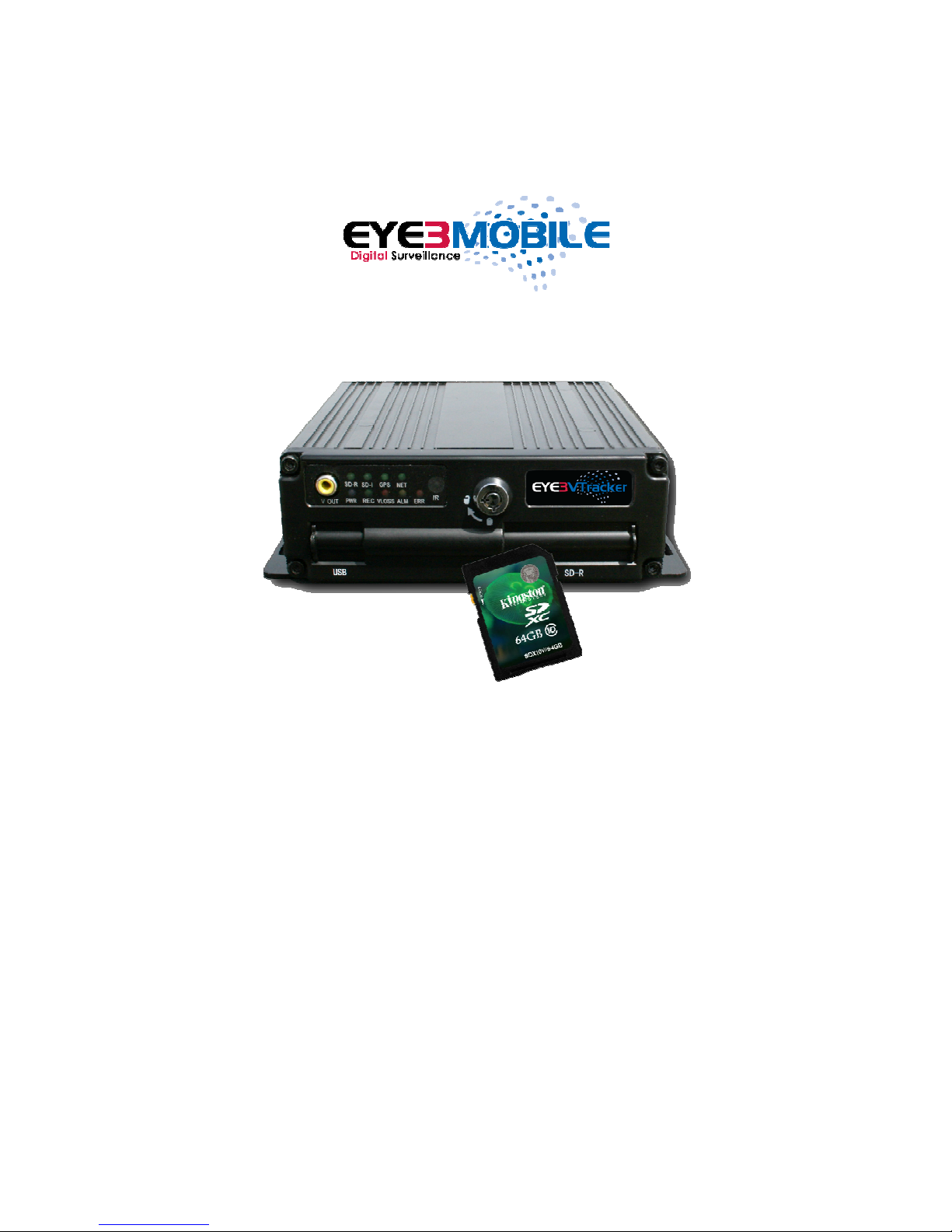
Eye3VTracker
4 Channel Mobile DVR
Installation Guide
Page 2

Table of Contents
Section 1: Inventory of Items
1.1: Inventory of Included Items
1.2: Optional Items
1.3: Alarm Extender
1.4: I/O Hub
1.5: A/V Cables
1.6: DC Power Conditioner
1.7: Lock Box
1.8: Eye360 Rear View Mirror
1.9: Eye3Motion Wireless Router
1.10 Wireless Microphone
1.11 Mobile LCD Monitor
1.12 Other I/O Devices
Section 2: Basic Setup
2.1: DVR Power Input
2.2: DVR Peripheral Connections
2.3: Eye3Motion Wireless Router
2.4: Mini LED Panel
2.5: Ruggedized Mobile LCD Monitor
2.6: Wireless Microphone
2.7: Inertia Sensor
2.8: Dash Control Panel
2.9: Eye360 Rearview Camera
Section 3: Troubleshooting
3.1: General Troubleshooting
2
Page 3
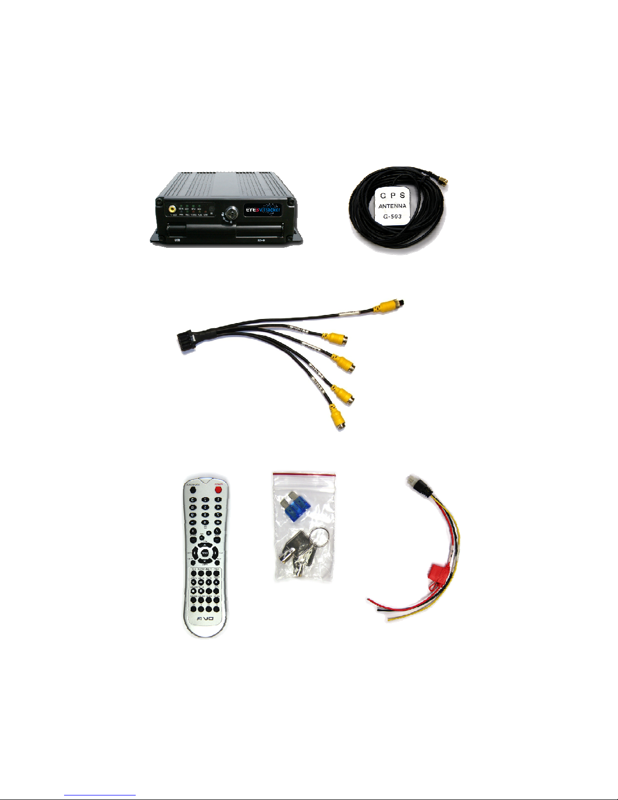
1.1 - Inventory of Included Items
VTracker DVR
001-054-001
Audio/Video
Bridle Cable
GPS Antenna
Remote Control
DVR Keys &
Spare Fuse
DVR Power Cable
3
Page 4
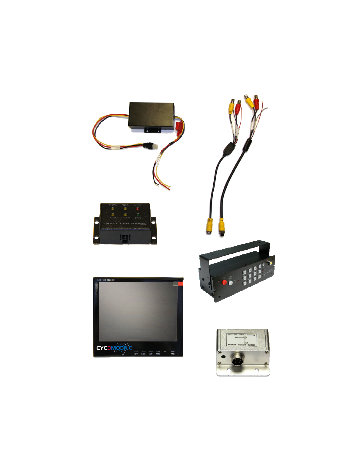
1.2 - Optional Items
DC Power Conditioner
003-054-014
DIN to BNC
A/V Adaptors
028-054-018(M)
028-054-019(F)
Mini LED Panel
003-054-009
Ruggedized Mobile
4
Dash Control Panel
003-054-007
LCD Monitor, 8”
006-069-001
Inertia Sensor
003-054-006
Page 5
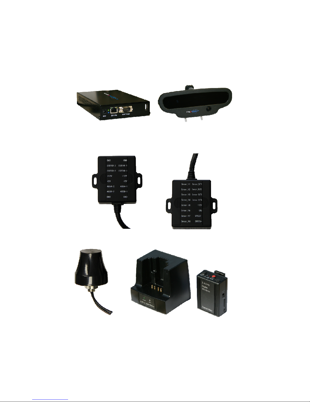
1.2
Eye3Motion Wireless Router
038-069-040 (3G/4G)
038-069-038 (WiFi)
038-069-034 (3G/4G/WiFi)
I/O Hub
003-054-011
Eye360 5-in-1
Rearview Camera
017-039-010
Alarm Extender
003-054-012
Dual GPS/WiFi
Antenna
038-056-003
Wireless Microphone and Charging Dock
003-021-001
5
Page 6
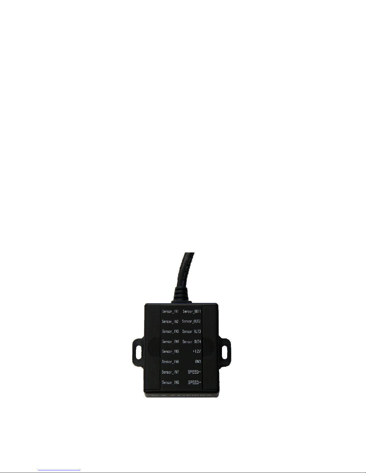
1.3 - Alarm Extender
The Alarm Extender is used to attach 8 custom sensors, supply 12v power output and
ground, relay sensor output, and as a secondary speed sensor.
The eight custom sensors can be configured to use a “normally open” or “normally
closed” circuit. This means that the sensor can be triggered either when positive voltage
is applied or when zero voltage is applied (ground). These sensors are commonly used
to tie into existing vehicle electronics such as brake lights, head lights, seat belts, turn
signals, hazard indicators, reverse gear, spot lights, roof mounted light bars, manual
emergency buttons, doors, or any other actuated device in the vehicle. These can each
be custom labeled in the DVR’s sensor configuration menu.
The two sensor relay output supply a positive 12v 250 mA signal when a sensor has been
activated. This can be used to actuate other devices in the vehicle, sounds alarms, or
flash secondary indicators on the dash.
The secondary speed sensor is used when the vehicle is equipped with a specific compatible speed sensor usually coming off of the transmission or ECU. This can be used
instead of GPS to determine vehicle speed by the DVR.
The power output can be used to power cameras, routers, switches, or other mobile accessories.
NOTE: DO NOT EXCEED 2.5 AMP DRAW THROUGH SENSOR PANEL. DO NOT
POWER MONITORS VIA THE SENSOR BLOCK.
6
Page 7
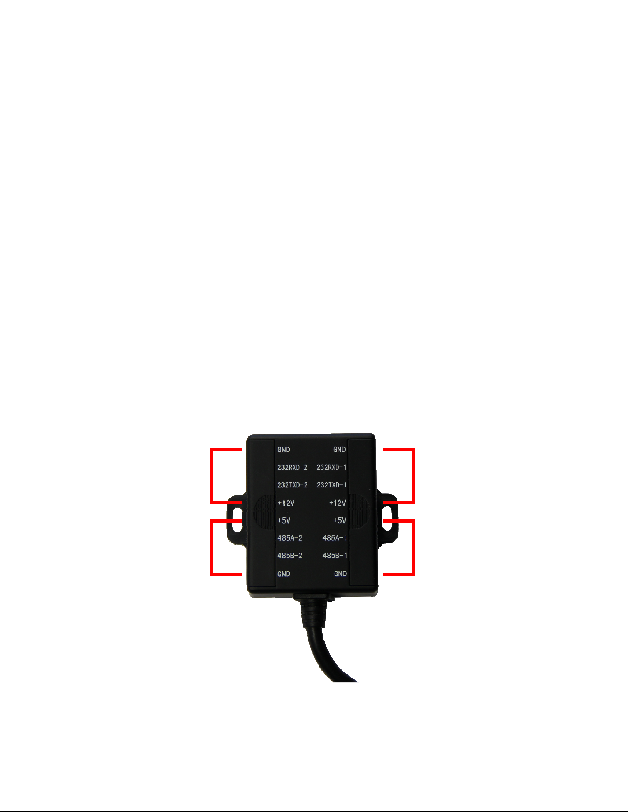
1.4 - I/O Hub
The I/O Panel is used to interface other external sensors and communication devices.
The I/O hub is comprised of two RS232 interfaces and two RS485 interfaces. These are
used for PTZ cameras, inertia sensor, mini control panel, dash control panels, and other
compatible devices. Please contact support for a complete list of accessories compatible
with your DVR model.
Use the following chart to program your device in the the DVR software:
RS232 1 -> COM 1
RS232 2 -> COM 2
RS485 1 -> COM 3
RS485 2 -> COM 4
Please see specific accessory schematics for more information on how to connect your
particular accessory.
NOTE: DO NOT EXCEED 2.5 AMP DRAW THROUGH I/O PANEL. DO NOT POWER
MONITORS VIA THE I/O PANEL.
COM 2
COM 4
COM 1
COM 3
7
Page 8
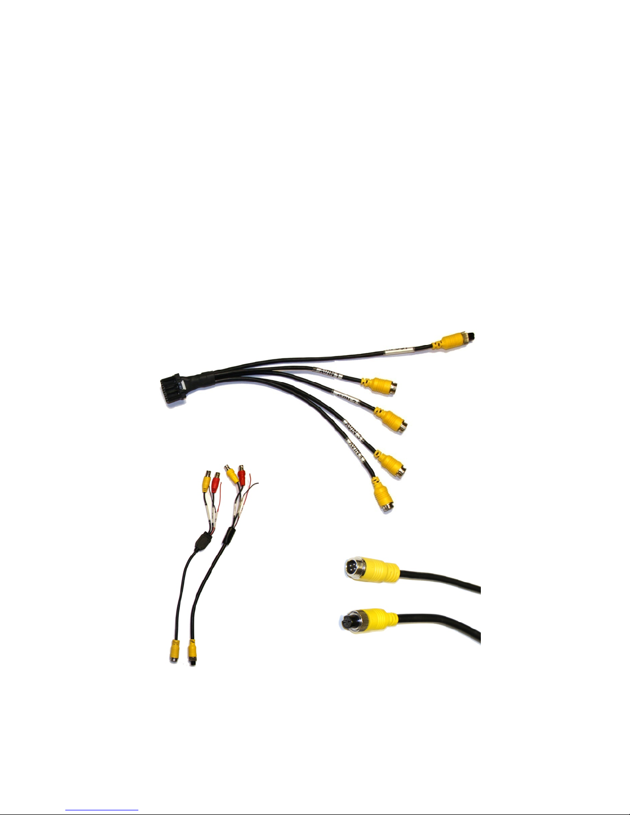
1.5 - A/V Cables
The DIN Audio / Video Bridle cable is used to attach cameras and monitors to the DVR. It
combines audio, video, power and ground all into one easy-to-connect thread secured
interface. Please make sure this cable is firmly connected to the rear of the DVR to ensure a stable audio and video signal.
There are five separate cables extending from the DVR connection. Four of these are
input cables. These are labeled and correspond to a channel number. AVIN1 provides
audio, video, and power for the channel number one and so on. If you did not purchase
our DIN cameras or you are using existing cameras which do not have a compatible DIN
connector, DIN to BNC adapters are available.
The fifth and final cable is for video output. This is used when the vehicle is being
equipped with a dash mounted LCD monitor, or for use when updating the settings on the
DVR system.
DIN A/V Bridle
DIN Adaptors
8
DIN Male
DIN Female
Page 9
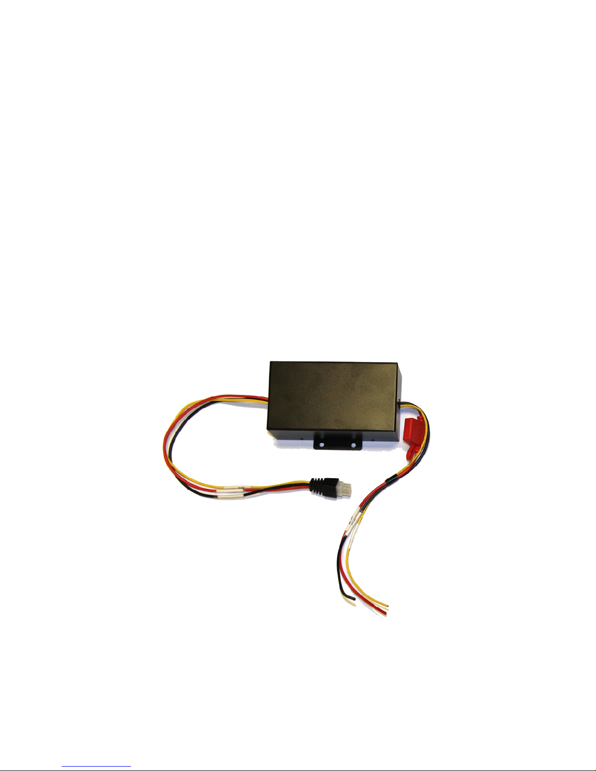
1.6 - DC Power Conditioner
The DVR comes with a built in 8v ~ 36v DC regulator. The built-in regulator provides
installation flexibility to varying auto-electric systems.
The purpose of the external DC Power Conditioner however, is to provide a solid steady
stream of current to the DVR. This conditioner comes with a 15amp fusible link to protect
the internal components from electrical surges. This conditioner accepts an 8v ~ 36v DC
irregular input (from the vehicle) and provides a steady DC output (to the DVR)
(Note: It is NOT a regulator it is current conditioner)
The DC Power conditioner is typically used in older vehicles or in vehicles which operate
considerable amounts of equipment simultaneously causing irregular electrical power
draw. Examples are Lift buses, special tactical vehicles, mobile communications centers,
and heavy equipment using an electric, hydraulic, or winching system.
9
Page 10
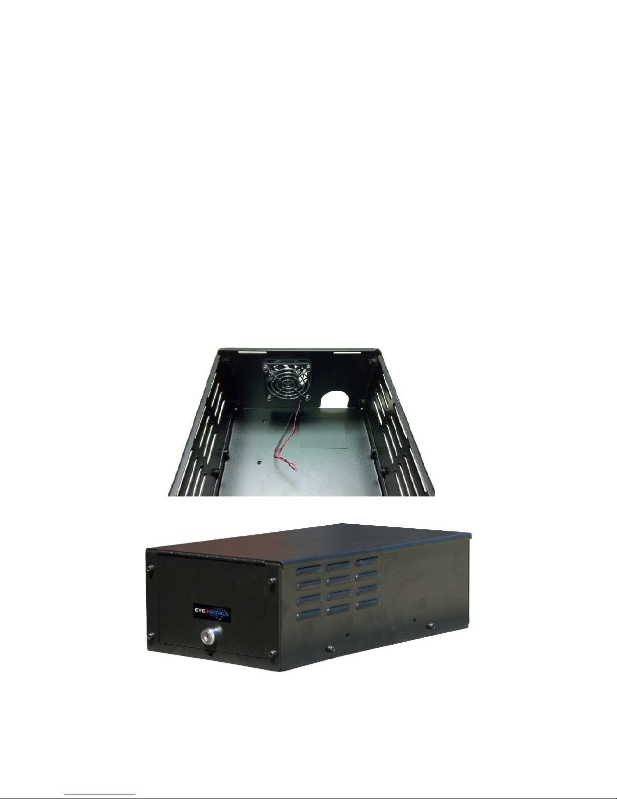
1.7 - Secure Lock Box
The lock box will come pre-assembled with the DVR, (Alarm Extender and I/O Hub if
purchased), and video bridle cable installed. To the rear of the lock box you will see an
opening revealing the audio and video connections.
To attach sensor/trigger wires, networking components, gps antenna, or other accessories, the lock box will need to be opened. The top of the lock box is removed by opening
the locked front with the provided key, unscrewing the hidden Phillips head screw, and
sliding the top to the rear.
The lock box can be mounted to any stable flat surface, however a horizontal orientation
is preferred. There are mounting tabs affixed to each side of the lock box with pre-drilled
mounting holes (not pictured).
The lock box also comes with (1) 12v exhaust fan at the rear. This is a 12v fan and will
come pre-connected to the 12v+ and Ground connections of the Alarm Extender.
10
Page 11

1.8 - Eye360 Rearview Camera
The Eye360 Rearview camera is designed to provide a 360° field of vision to the DVR
using 4 wide angle lens cameras and one zoom camera. These cameras are located on
the front, rear, and sides of the rearview mirror and are angled so that they provide a
straight line of sight to the windshield, side doors, and interior with no blind spots when
the mirror is adjusted for standard use. The zoom camera can be engaged by flipping the
switch located on the bottom of the mirror and overrides the normal magnification front
view camera.
In addition to the built-in cameras, the Eye360 Rearview camera includes a video input
feed that overrides the interior camera view when the toggle switch on the back of the
mirror is flipped. If another camera is installed in the vehicle it can be connected to this
input feed. This allows, for example, the direct monitoring of the prisoner cage in police
vehicles when a suspect is in custody.
Finally the Eye360 Rearview camera has a built-in microphone that will output an audio
feed from the cabin of the vehicle. This microphone can be turned on or off by flipping the
second switch located on the bottom of the mirror.
11
Page 12
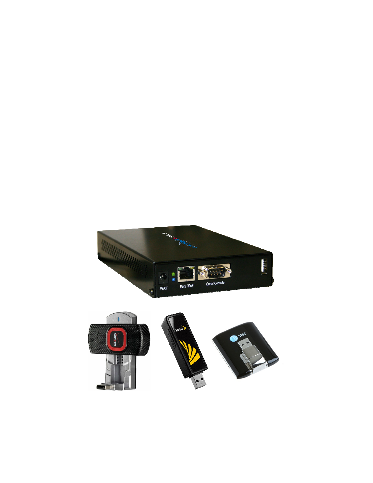
1.9 - Eye3Motion Wireless Router
The Eye3Motion Wireless Router allows for wireless transmission of video from the DVR
to a remote computer or smartphone. This device can be configured to connect to cellular data networks and/or predefined WiFi hotspots. When the Eye3Motion is connected to
the DVR via an RJ45 Ethernet cable and cellular or wifi networks are in range, the DVR’s
GPS location and live camera feeds can be monitored in real time by logging on to the
LiveView service available at cms.eye3mobile.com
Power for the router should be supplied via the 12V and Ground on the Alarm Extender
that connects to the rear of the DVR. Additionally, the WiFi/GPS Dual Antenna must be
connected to the router if WiFi functionality is required.
NOTE: WHEN UTILIZING A 3G/4G CELLULAR DATA CONNECTION, A USB CELLULAR DATA CARD MUST BE PLUGGED INTO THE USB PORT ON THE FRONT OF
THE EYE3MOTION
12
Compatible Cellular Data Cards
Page 13
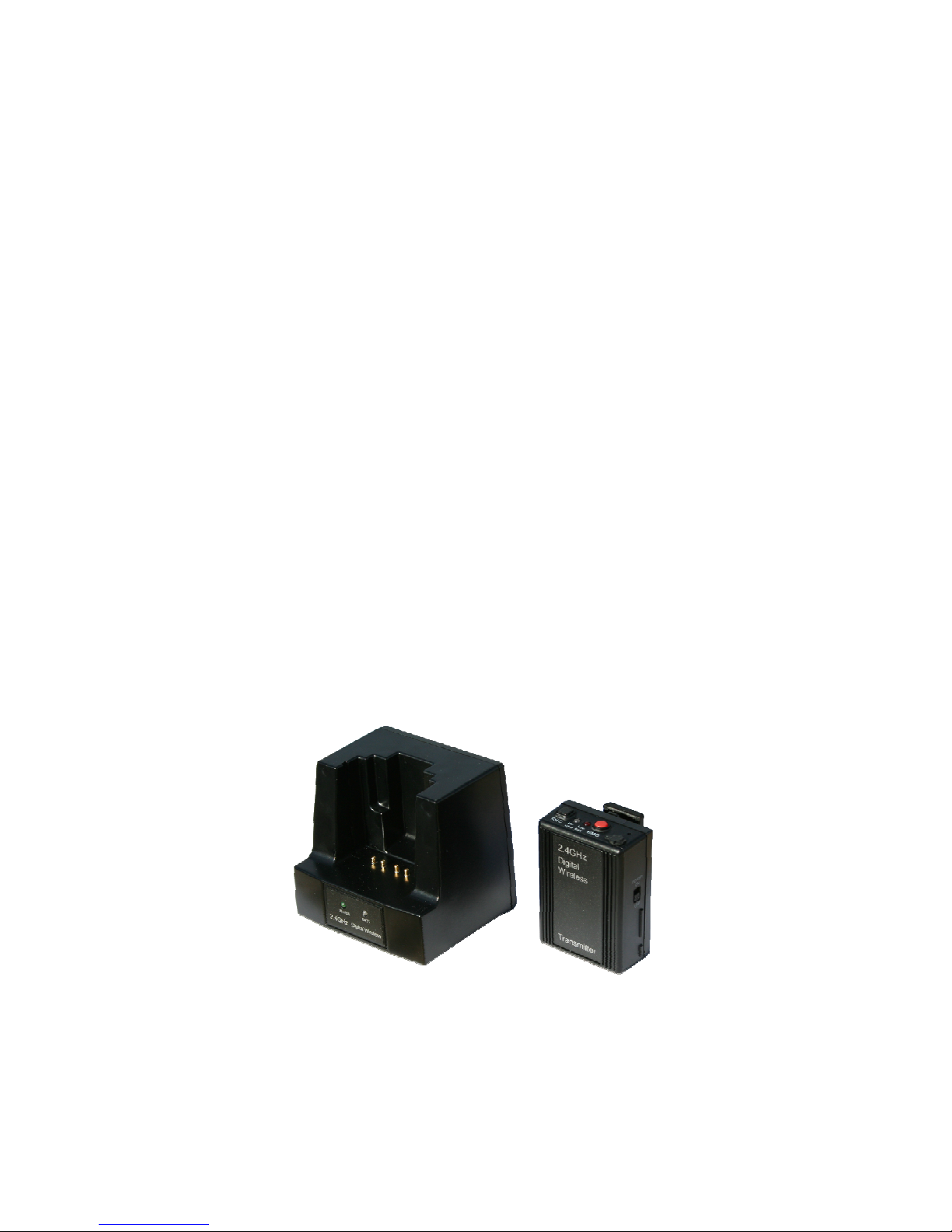
1.10 - Wireless Microphone
The wireless microphone allows the user to clip the body pack onto their belt or clothing
and wirelessly transmit an audio feed back to the docking station at a range of up to 1000
feet. When not in use, the body pack’s internal lithium ion battery is recharged in the
docking station.
Audio recording is activated by pressing the [REC] button on the body pack. This also
triggers a signal relay that can be used to create an event in the DVR’s recording timeline
whenever audio capture is in progress. There is also a red emergency button [EMG] that
can be used to trigger an auxiliary relay in the docking station. This can be used to activate a light bar, shotgun rack, or some other mechanism in the vehicle remotely when
properly integrated.
This accessory features one microphone built into the body pack and an external mic with
lapel clip that can be plugged into the body pack to focus on the wearer’s voice. Alternately, the external mic can be plugged into the docking station to record in-vehicle audio.
The docking station is connected to the DVR and powered via the 12V and Ground on
the Alarm Extender. This allows for the DVR to detect the relay output from the dock and
respond appropriately. Lastly, there is a relay input feature that can be used to initiate
recording automatically based on an external voltage event.
13
Page 14
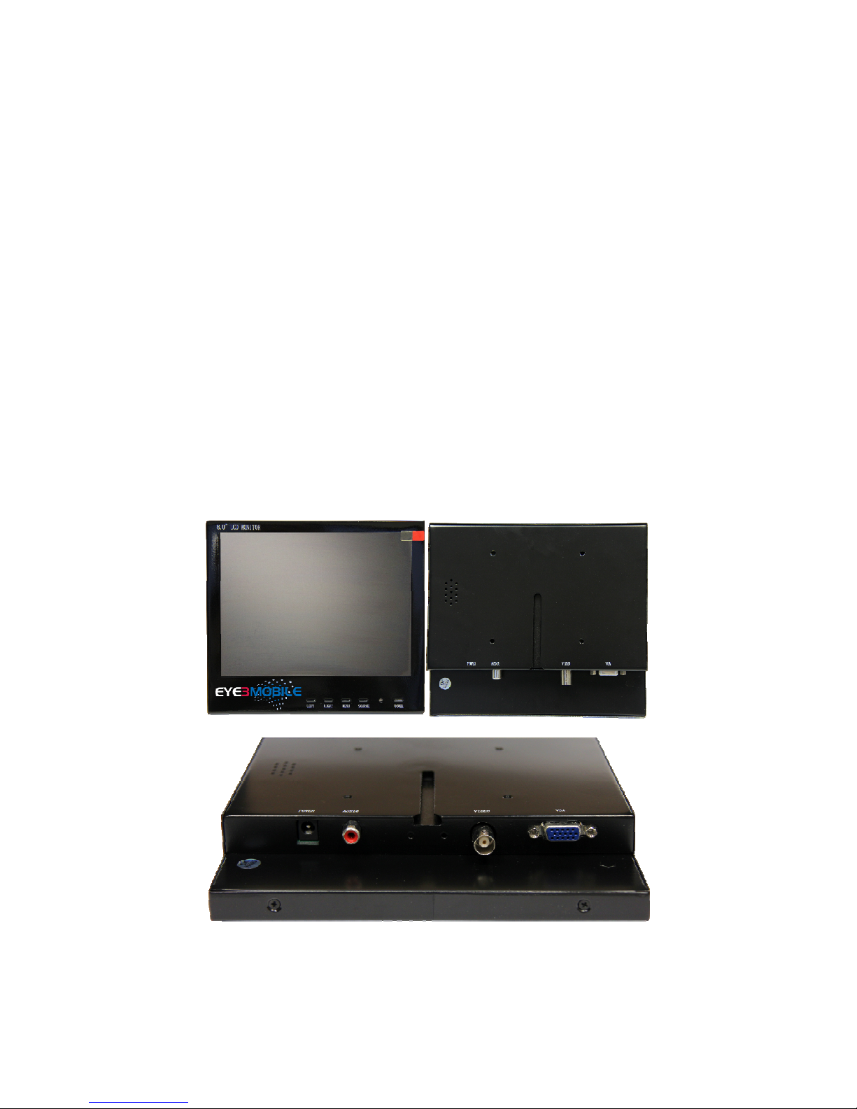
1.11 - Mobile LCD Monitor
The 8” Ruggedized Mobile LCD Monitor allows the driver of the vehicle to see a live view
the camera feeds from the DVR. It’s all steel construction and heavy duty slide mount
ensure reliable operation in demanding mobile conditions.
The monitor features both VGA and BNC video inputs as well as RCA audio input. The
video input source can be switched between the DVR and a PC/laptop with the single
press of a button. Resolutions of up to 1600x1200 are supported for VGA sources. Two
styles of mounting fixtures are included, a standard channel lock stand and a two part
dovetail slide mount. Either can be utilized depending on the application.
The monitor requires 12V DC power to operate and can be powered directly by the vehicle’s wiring or by utilizing the included DC adapter and a standard 110V outlet.
NOTE: DO NOT ATTEMPT TO POWER THE MONITOR DIRECTLY FROM THE DVR’S
12V OUTPUT TERMINALS.
NOTE: WHEN USING THE REMOTE CONTROL TO ACCESS THE DVR’S INTERNAL
MENU, REMOTE MUST BE POINTED AT THE FRONT OF THE DVR UNIT, NOT THE
MONITOR.
14
Page 15
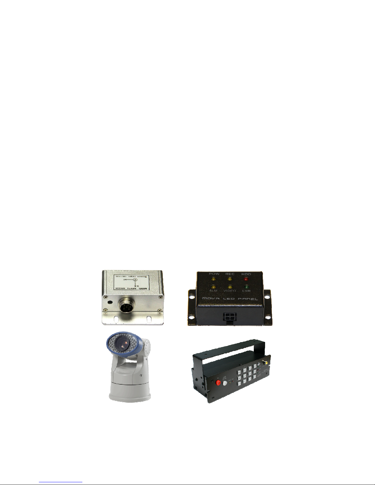
1.12 - Other I/O Devices
The two primarily used I/O devices are the Mini LED Panel and the Inertia Sensor.
The Inertia Sensor connects to the DVR via the I/O Hub and provides the DVR with
acceleration information on the X,Y and Z axes. This allows the DVR to be configured to
flag an event when it experiences acceleration outside of the user defined threshold as
measured in G’s. The Inertia Sensor also has a thermometer built in that will report the
external temperature to the DVR allowing for event flagging based on High or Low temperature parameters as well.
The Mini LED Panel connects to the DVR via the I/O Hub and simply forwards the indicator lights that are displayed on the front panel of the DVR to another location. This allows
for driver monitoring of the DVR’s status when it is installed in a lockbox, trunk, or other
driver inaccessible area. The LED’s indicate presence of power to the system, whether
the DVR is actively recording, Whether a Hard Drive is present in the system, when an
alarm event is active, when a video channel is not receiving a signal, and when a general
error is detected.
The Dash Control Panel connects to the DVR via the I/O Hub and allows the driver to
navigate the DVR’s menu system and/or utilize the remote control. This is required when
the DVR is installed in a location that is not within a direct line of sight for the driver and
using the remote control would therefore not be otherwise possible.
Other RS485 and RS232 devices such as controllable PTZ cameras are also supported.
The DVR has native support for both the Pleco-P and Pelco-D communications protocols.
15
Page 16
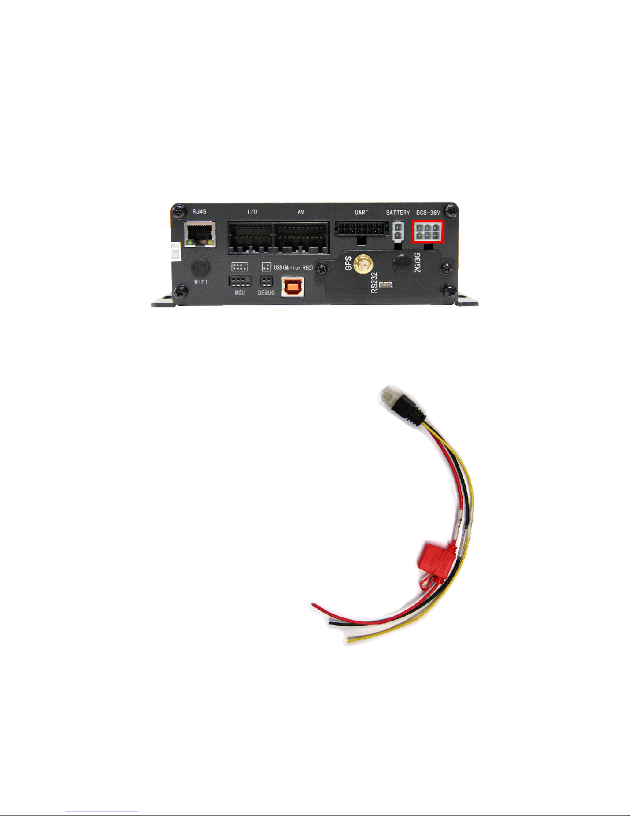
2.1 - DVR Power Input
• The DVR can accept input power ranging between 8
and 36 Volts.
• Connect the Red wire to a +V source. Make sure this is
a “clean” connection to the battery or voltage regulator.
Excessive noise on the power line can effect the DVRs
performance.
• Connect the Yellow wire to a 12v signal from the ignition
switch. This can come from an existing wire (car stereo)
or directly from the ignition switch.
• Connect the Black wire to a solid ground. The frame or
engine block are both good sources for grounding.
NOTE: THIS IS THE ONLY POWER INPUT REQUIRED
FOR THE DVR
16
Page 17
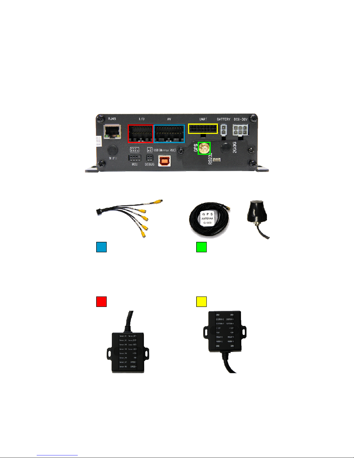
2.2 - DVR Peripheral Connections
Or
Audio/Video
Bridle Cable
Alarm Extender
GPS Antenna
I/O Hub
17
Page 18
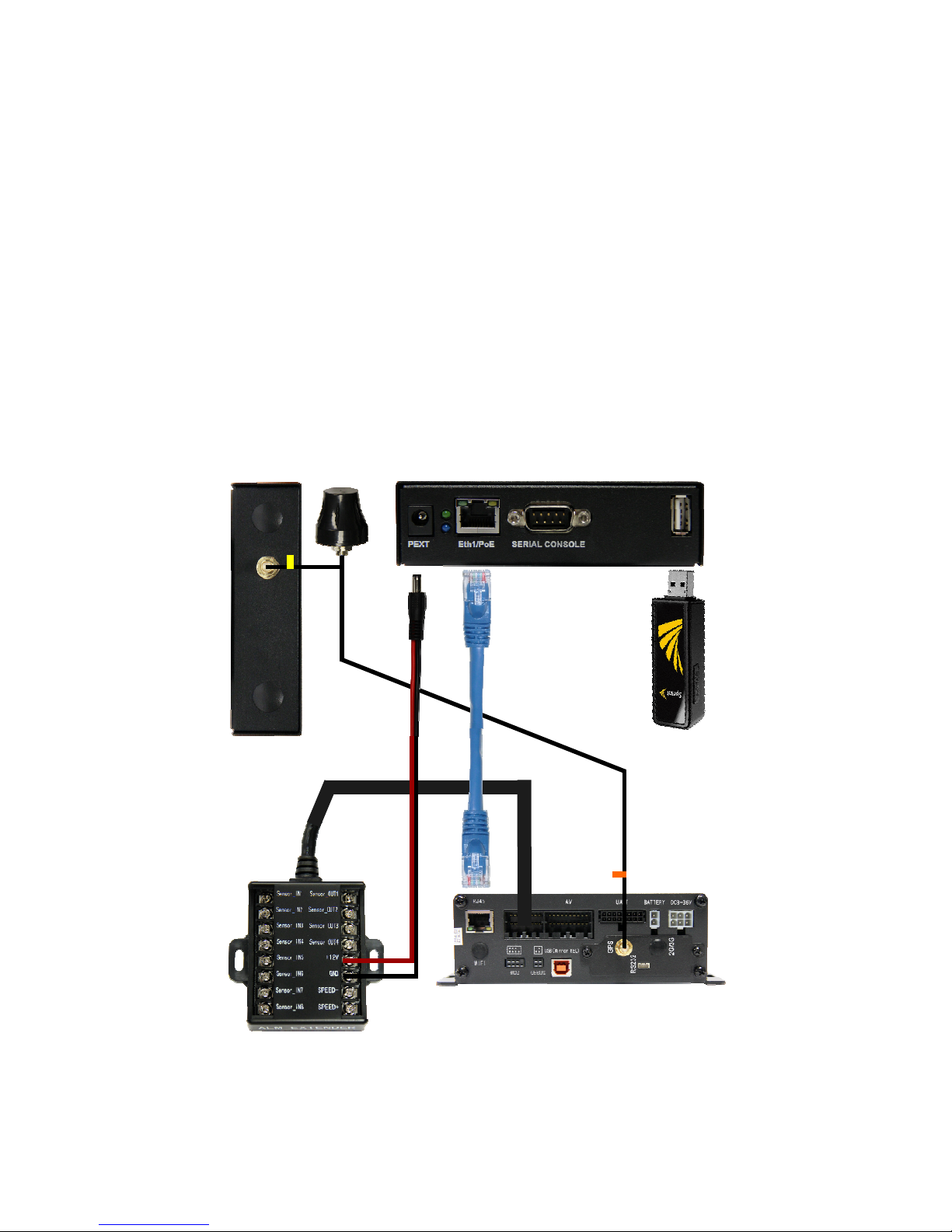
2.3 - Eye3Motion Wireless Router
• The Eye3Motion wireless router is powered by the DVR via the 12v and ground termi
nals on Alarm Extender accessory. This allows the router to operate only when the DVR
is running. Any alternate 12V power source is also acceptable, however it should correspond to vehicle ignition to avoid draining the battery when the vehicle is not in operation.
• The Eye3Motion Router is connected to the DVR via an RJ-45 Ethernet cable.
• If a 3G/4G cellular data connection is desired, the compatible USB data card must be
plugged into the USB port on the rear of Eye3Motion Router
• If a WiFi enabled Eye3Motion Router is being utilized, the WiFi lead from the Dual Antenna must be connected to the SMA connector on the front of the Eye3Motion Router.
Eye3Motion Front
Eye3Motion Rear
18
VTracker
Page 19
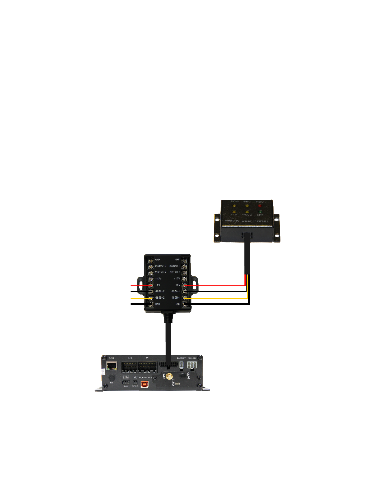
2.4 - Mini LED Panel
• The Mini LED Panel communicates with the DVR via it’s connection to the I/O Hub.
There are two data channels that may be used, either COM 3 or COM 4.
• The DVR must be configured to use the Mini LED Panel under its peripheral configuration menu, therefore it is important to be sure that the selected COM channel on the DVR
matches the wiring of the Mini LED Panel.
• The peripheral option for the selected COM channel must be set to “CONTROL PANEL”
on the DVR’s menu: SETTINGS > PERIPHERAL > EXT. COM SETUP
NOTE: THE DVR MUST BE REBOOTED AFTER THE MINI LED PANEL IS CONNECTED IN ORDER FOR IT TO BEGIN RELAYING ACCURATE LED ACTIVITY.
VTracker
COM 3 COM 4
19
Page 20
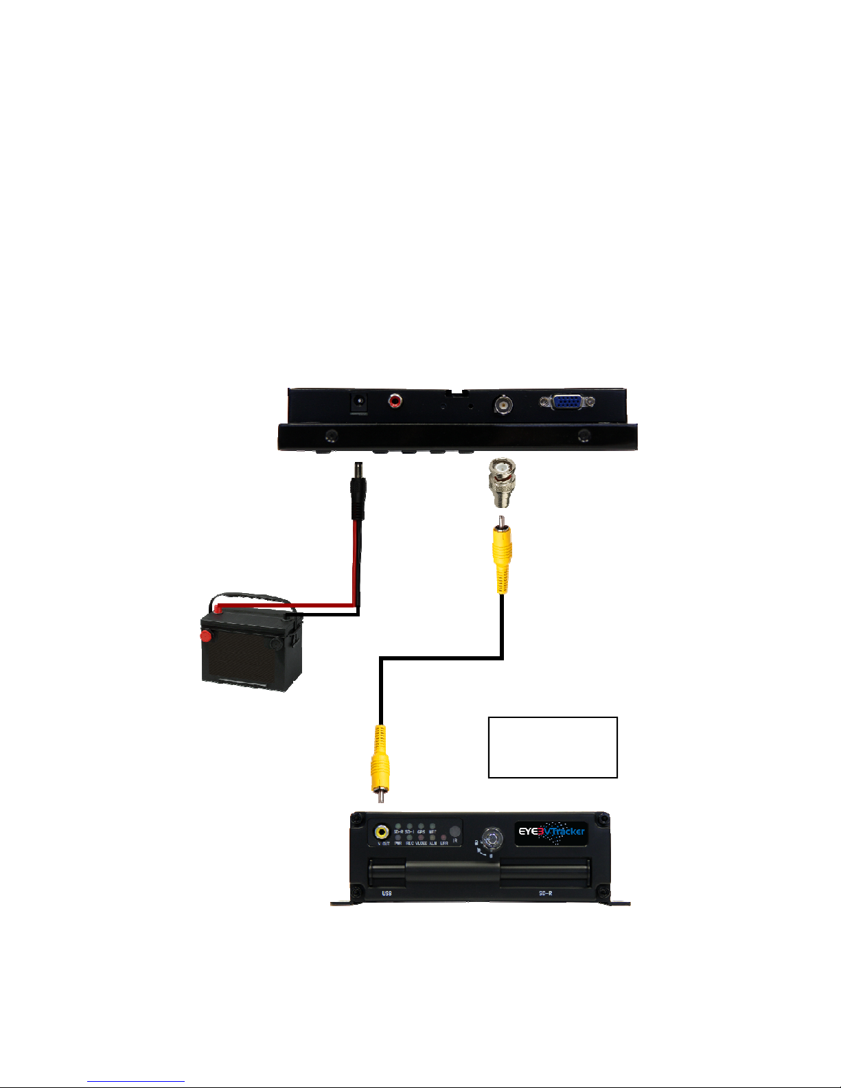
2.5 - Ruggedized Mobile LCD Monitor
The Mobile monitor can be connected to either the RCA Video output on the front of the
DVR or alternately, to the A/V Out DIN connector on the A/V bridle cable. Using the rear
DIN A/V output connector will require an additional male DIN to BNC adapter.
NOTE: DO NOT ATTEMPT TO POWER THE MONITOR FROM THE 12V OUTPUT OF
THE DVR OR ITS PERIPHERALS.
External 12V
Source
20
Option 1: When
using VTracker
front RCA output.
Page 21
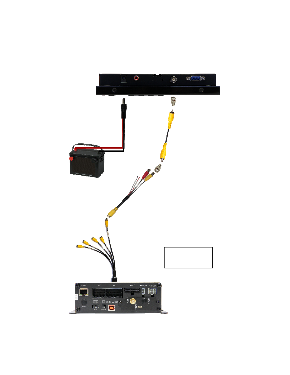
2.5
External 12V
Source
Option 2: When
using VTracker rear
DIN A/V output.
21
Page 22
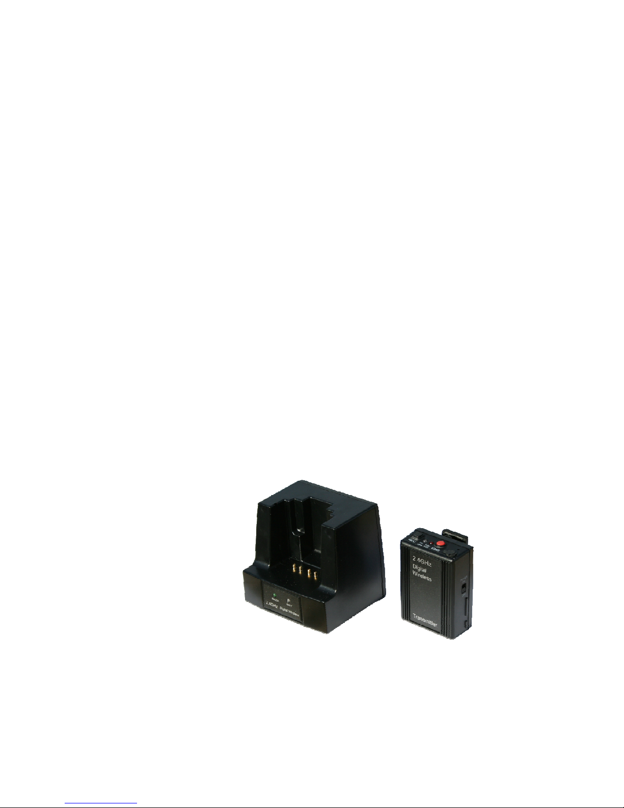
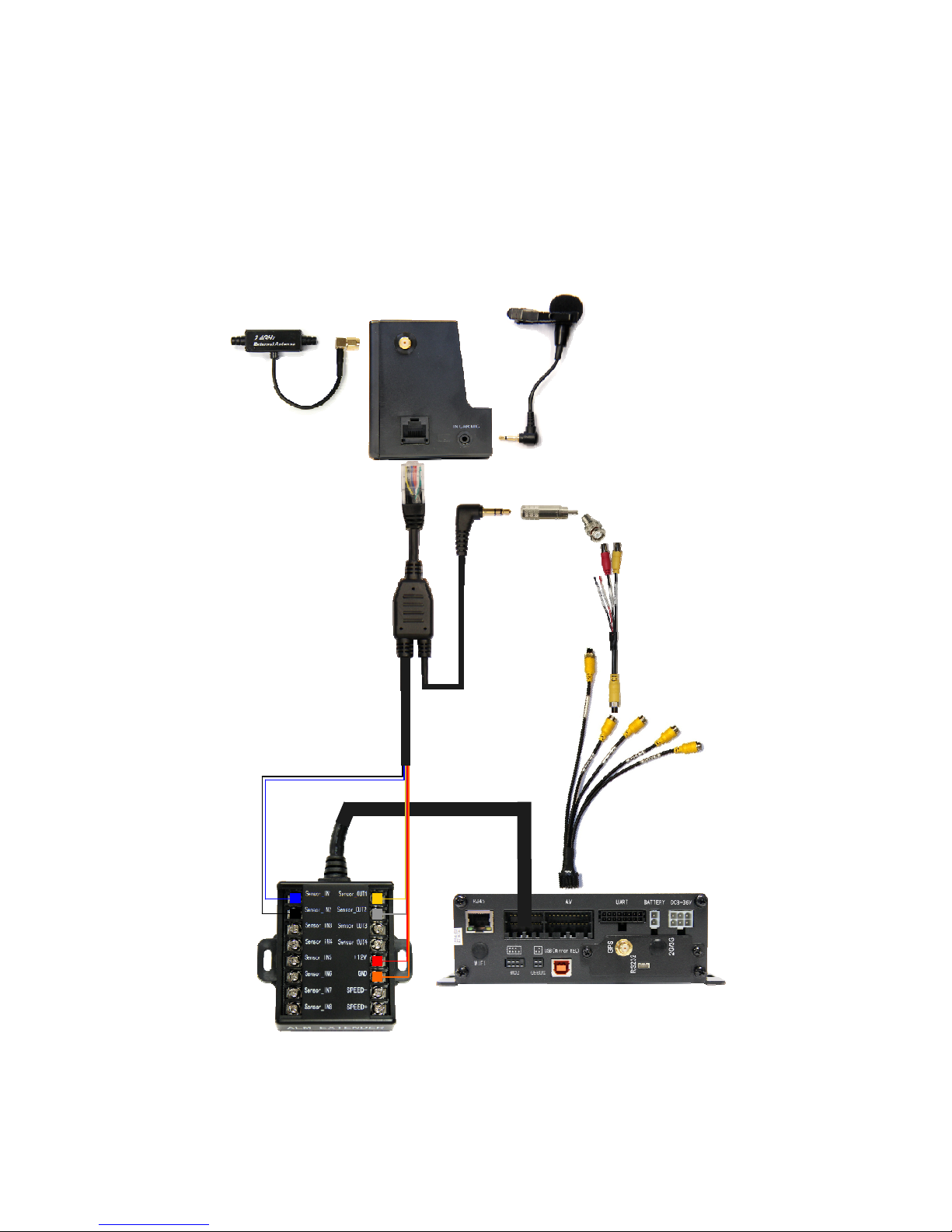
2.6 - Wireless Microphone
The wireless microphone consists of a receiver/charging dock and a belt pack that allows
for the recording of an audio feed from distances of up to 1000 feet from the receiver.
There are three microphone configuration options: one microphone built into the belt
pack, one lapel mic that attaches to the belt pack and can be clipped onto the clothing,
and an extension mic that plugs into the dock to allow recording of audio inside of the
vehicle.
Audio recording is initiating by taking the belt pack off of the dock and pressing the “REC”
button. This begins transmission of the audio stream from the belt pack to the receiver in
the dock. The audio output from the dock is connected to the audio input on one of the
channels of the DVR. This also triggers a 12V relay in the dock that can be used to flag
the video timeline on the DVR with an event whenever audio is recording. The second
button on the belt pack is marked “EMG” and can be used to trigger a secondary 12V
relay. This can be used to activate 3rd party equipment when the button is pressed or to
flag a different event type on the video timeline of the DVR. In the wiring diagram below,
both 12V relays are connected to the DVR but this can be changed based on a given use
case scenario.
In addition to the output relays, there are also two input relays. These can be used to
trigger audio recording automatically based on external events, for example when a light
bar is turned on or when the DVR detects that the vehicle has exceeded a predefined
speed threshold.
NOTE: THE DVR WILL NOT RECORD AUDIO ONLY. AUDIO MUST BE PAIRED WITH
A VIDEO FEED USING THE DIN TO BNC ADAPTER CABLES.
22
Page 23
2.6
23
Page 24
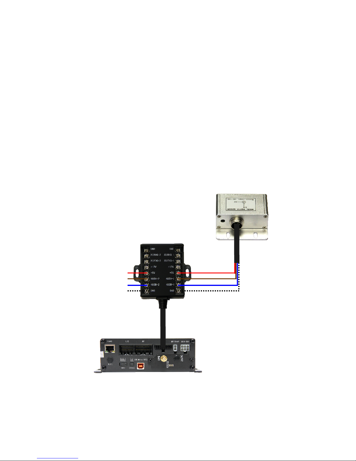
2.7 - Inertia Sensor
• The Inertia Sensor communicates with the DVR via it’s connection to the I/O Hub. There
are two data channels that may be used, either COM 3 or COM 4.
• The DVR must be configured to use the Inertia Sensor under its peripheral configuration
menu, therefore it is important to be sure that the selected COM channel on the DVR
matches the wiring of the Inertia Sensor.
• The peripheral option for the selected COM channel must be set to “ACCELERATION”
on the DVR’s menu: SETTINGS > PERIPHERAL > EXT. COM SETUP
NOTE: THE INERTIA SENSOR MUST BE CALIBRATED BEFORE USE BY SELECTING THE “CALIBRATE” OPTION ON THE DVR’S MENU:
SETTINGS > EVENT > ACCELERATION
24
COM 3 COM 4
VTracker
Page 25
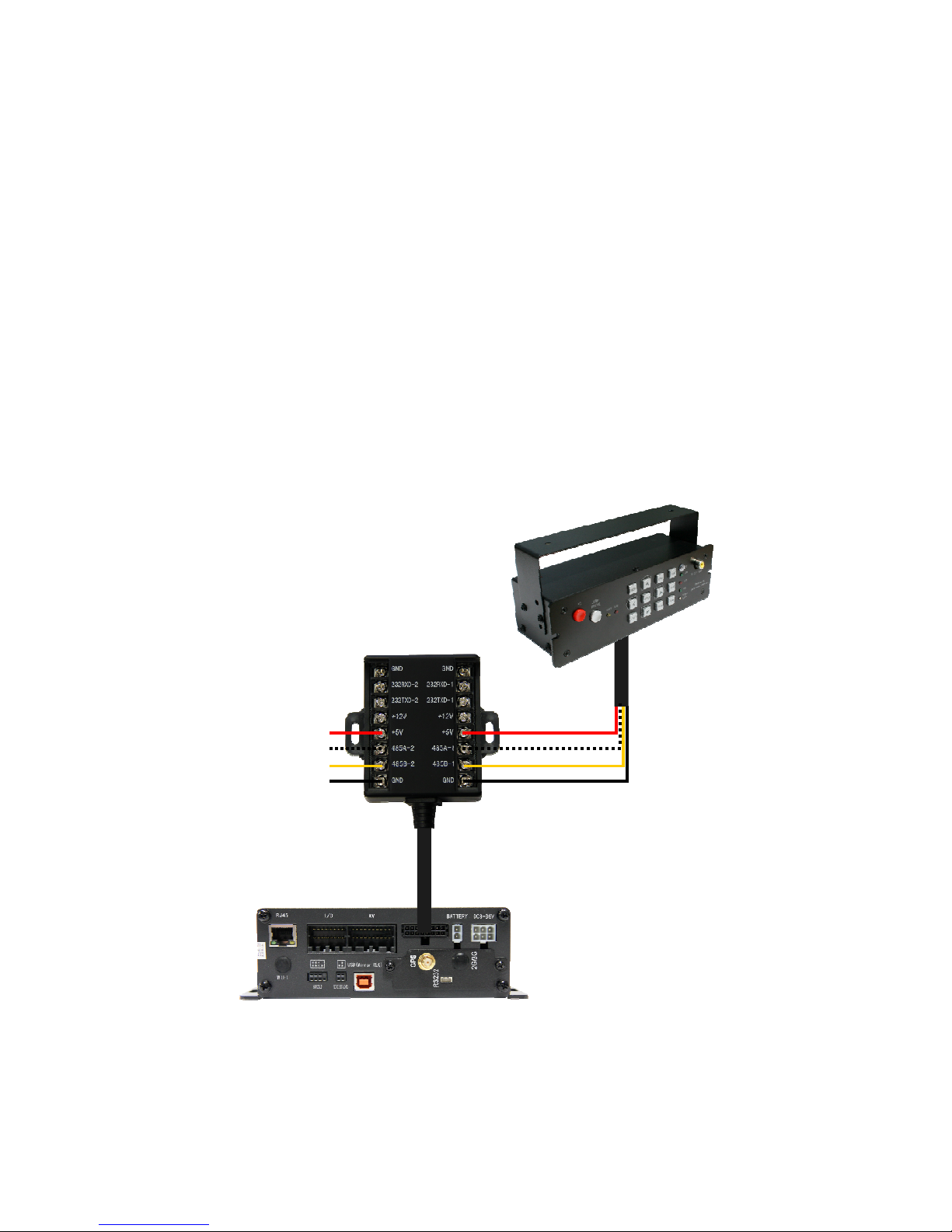
2.8 - Dash Control Panel
• The Dash Control Panel communicates with the DVR via it’s connection to the I/O Hub.
There are two data channels that may be used, either COM 3 or COM 4.
• The DVR must be configured to use the Dash Control Panel under its peripheral configuration menu, therefore it is important to be sure that the selected COM channel on the
DVR matches the wiring of the Dash Control Panel .
• The peripheral option for the selected COM channel must be set to “CONTROL PANEL”
on the DVR’s menu: SETTINGS > PERIPHERAL > EXT. COM SETUP
VTracker
COM 3 COM 4
25
Page 26
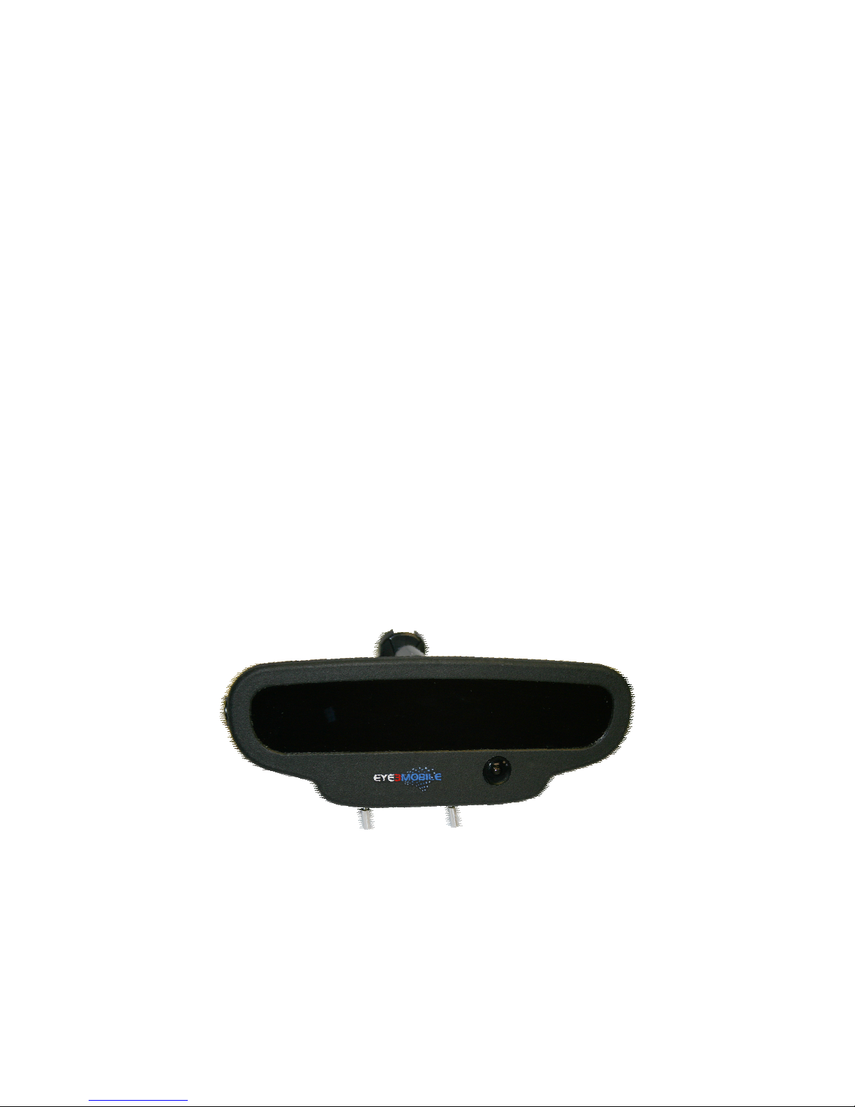
2.9 - Eye360 Rearview Camera
• The Eye360 Rearview Camera replaces a vehicle’s standard rearview mirror and provides 4 video feeds that overlap to cover a 360° view from the driver’s perspective with no
blind spots. These cameras record the windshield, driver’s side, passenger side, and
interior of the vehicle.
• There is a built in microphone that can be enabled to record audio inside the vehicle at
the flip of a toggle switch. This output can be connected to any one of the 4 audio inputs
on the DVR but must accompany a video feed. The system will not record audio if there is
no video input on a given channel.
• A second toggle switch changes between two camera feeds, the wide angle forward
view and a 10x zoomed forward view. This allows for the quick and easy capture of license plate numbers and other fine details from a distance during traffic stops.
• Finally, a flip switch on the back of the mirror replaces the interior view of the driver with
an auxiliary video feed. This can be connected to an additional camera of your choosing
such as an external PTZ camera or a backseat prisoner camera. This brings the total
number of possible camera views to 6, although only 4 can be displayed or recorded at
any given time.
26
Forward Zoom
On/Off Switch
Microphone
On/Off Switch
Page 27
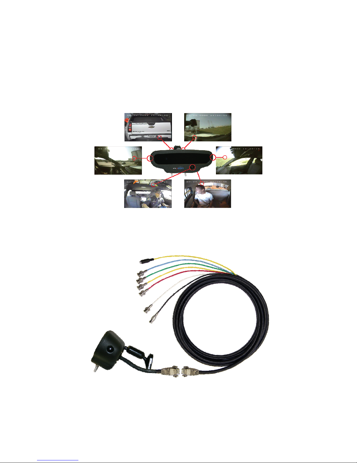
2.9
Forward View Forward Zoom
Driver’s
Side View
Passenger
Side View
Interior View Auxiliary View
Audio/Video/Power
Cable
27
Page 28
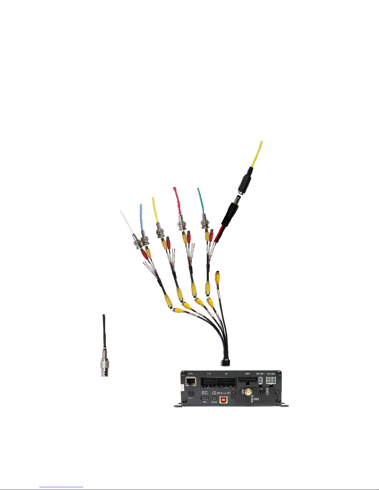
2.9
Microphone
Output (1)
12V DC Input
Video Outputs (4)
Auxillary
Video Input
28
Page 29
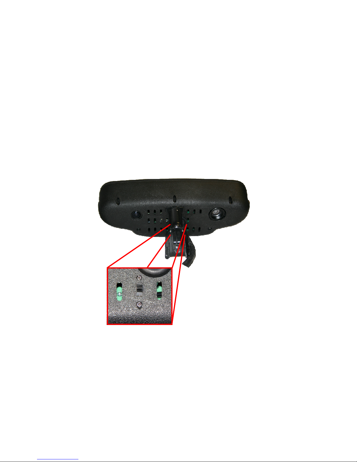
2.9
Auxiliary Video
Feed Switch
29
Page 30

3.1 - Troubleshooting
My DVR has power but will not turn on.
Power is indicated by a blue power light on the front of the DVR. When
the unit is “sleeping” this will be the only light illuminated. When the dvr
is fully functioning you will have a green record light, as well as a GPS
light (for units with GPS). If the unit is not coming on verify the following:
• The lock is in the locked position
• The Ignition voltage source is turned on
• The unit has not been programmed for scheduled operation
• The unit has not been turned off via the power button on the
remote control
My DVR is not getting a blue power light.
The blue light indicates that a valid power4 source is connected. This
must be 8v ~ 36v. If you are not getting a blue light, check the following:
• All fuses are intact
• All wiring is connected securely
• All grounding connections are to the vehicle chassis or the
engine block
• DVR power connector is fully plugged in
• Battery has 12v output
My DVR is on but not recording.
Recording is indicated by the record light and storage media activity is
indicated by the SD or HDD light depending on your. If the unit is not
recording please try the following:
• Verify storage media is attached (SD Memory card or Hard
Disk Drive)
• Verify storage media is formatted using the DVR’s firmware
30
Page 31

My Camera has picture but no sound.
If your cameras have built in microphone and you are not receiving audio, please check the following:
• Audio is enabled on that channel in the DVR firmware
• The cables are firmly connected to the AV bridle cable
• Live audio has been enabled in the DVR firmware
• AV bridle cable is securely connected to the DVR
My Camera has no picture.
If your camera is not providing a picture or you are getting a video loss
error, check the following:
• AV bridle cable is securely attached to the DVR
• Camera cable is securely connected to the AV bridle
• Camera is getting power (for IR cameras, obscure the light
sensor and verify IR LEDs turn on)
• DVR is powered on and is operational
• Channel has been enabled in the DVR firmware
Please contact technical support for further issues at 888-777-9059 or
[email protected]
31
Page 32

Eye3Data
9624 Cincinnati-Columbus Rd.
Cincinnati, OH 4524 1 USA
Web site: www.eye3mobile .com
Local Phone: 513-779-0604
North American Support: 888-777-9059
LEGAL NOTICE:
Copyright ©2013 Eye3Data. All rights reserved. Eye3Data, Eye3,
Eye3VTracker are registered trademarks of MAI Media Group, LLC.
32
 Loading...