

Page 1

GM/GS series
CO, CO2
Gas monitoring transmitter / Indoor
Operation manual
Page 2

Gas monitoring transmitter. Operation manual
PAGE:2 OF 30
Ver:01
1. Summary ...................................................................................................................................... 3
2. Security considerations ................................................................................................................. 4
3. Housing, Dimension & Installation ................................................................................................ 6
4. Hardware Feature ......................................................................................................................... 7
5. Signal Connection ......................................................................................................................... 8
6. Software Feature & Using ............................................................................................................. 9
7. GM/GS PRODUCT UI operation step ...................................................................................... 11
7.1 Execute “GTH UI” .................................................................................................................. 12
7.2 Connect to PC via RS-485 .................................................................................................... 13
7.3 Scan RS-485 connection ...................................................................................................... 16
7.4 Setting RS-485 communication format .................................................................................. 21
7.5 Select Parameter of Output ................................................................................................... 23
7.6 CO2 Self-Correcting ADC ..................................................................................................... 25
8. Protocol ...................................................................................................................................... 27
9. Factory Default Setting ............................................................................................................... 28
9.1 Suggested Setting .................................................................................................................... 28
10. Cautions ................................................................................................................................... 29
11. Inspection and Maintenance ..................................................................................................... 30
Page 3

Gas monitoring transmitter. Operation manual
PAGE:3 OF 30
Ver:01
1. Summary
1.1 Features
1. Non-Dispersive Infrared (NDIR): For detecting the CO2 Concentration.
2. COMS Sensor: For detecting the Temperature and Humidity.
3. Electrochemical sensor: For detecting the CO Concentration.
4. Two-electrode electrochemical sensor: For detecting the Formaldehyde.
5. iAQ Sensor: For volatile gases
6. Remote monitor by RS-485 (Modbus RTU).
7. Customized Monitoring System.
8. Providing software can be set and read the records.
9. GTH UI:
a. Set the Category of Physical Output & Measuring Range.
b. CO2 Concentration Detection. It provides the setting features to On/ OFF for Self-Correcting ABC
Algorithm.
c. RS-485 Port No.
d. Different Baud Rate for data transmission.
1.2 Applicable Fields
a. The ventilation system for various building.
b. The HVAC process as Heating, Ventilation and Air Condition.
c. Monitor temperature & humidity, CO, CO2 for house and building.
Page 4
Gas monitoring transmitter. Operation manual
PAGE:4 OF 30
Ver:01
2. Security considerations
2.1. Manual Guide
Before using this product, the user must to read the details of this user’s manual, then use this product
with correct steps. This user’s manual is for reference while Using/ Setting this product, and required to
conserve properly.
Solemn Statement:
1. This product is improperly to used in explosion-proof area.
2. Do not use this product in dangerous situation where human health & life may be threaten & affected.
2.2. Improper Installation Environment
In additional, if the user install this product in special environments as Dust-Free Room, Breed
Environment for Animals, etc, please initiate a specialized product consultation to our professional sales
of EYC-TECH.
2.3. Illustration, Warning & Attention
If the improper & dangerous results which result from improper operator or improper environment,
EYC-TECH will not bear any legal responsibility
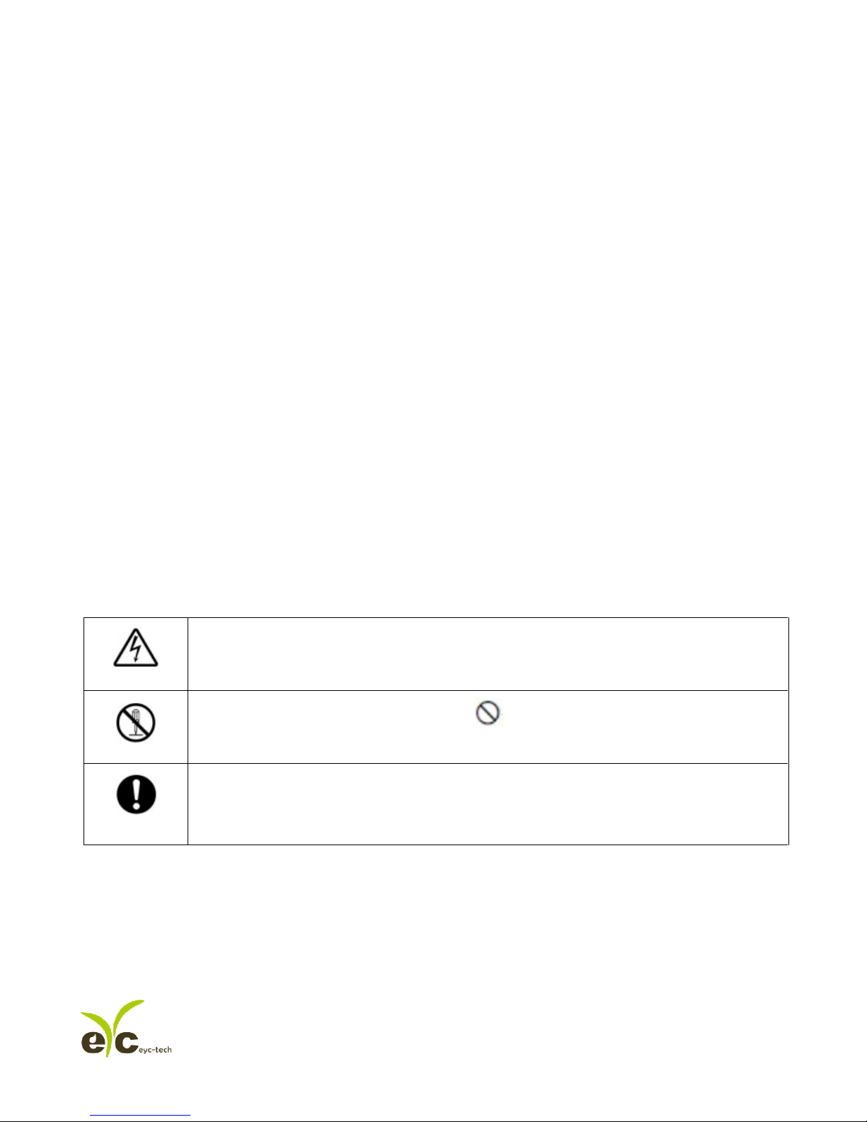
Illustration
This mark is to give advice & warning for the potential dangerous which result from
obvious wrong/ improper operation steps. (The left mark means “Watch out for electric
shock”)
In order to avoid the dangerous situation, this mark means some special operation/
action is forbidden to implement. (The left mark means “Forbidden to Disassemble”)
In order to avoid the dangerous situation, this mark means Specified Action/ Operation is
required to implement. (The left mark means “General Instruction”)
Page 5
Gas monitoring transmitter. Operation manual
PAGE:5 OF 30
Ver:01
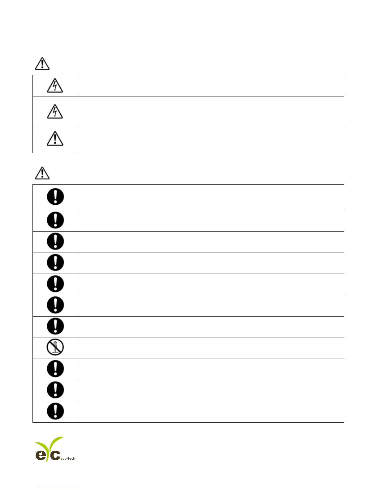
Warning
Please implement the wiring operation under power-off status; otherwise it will cause
electric shock, or become the root cause of machinery breakdown.
This product must be operated under ruled power supplying value, and be operated under
the ruled normal operation conditions which described in the user’s manual; otherwise it
may cause the disasters as fire accident or be the root cause of machinery breakdown.
Please install this product under normal pressure status. Otherwise it may cause the safety
problems.
Attention
In order to be in accordance with all applicable safety standards. The installation & wiring
must be performed by qualified installer & professional instruments.
Please ensure the outlook/ outbox do not have any damage which result from improper
transportation, or malfunction which results from lost attachments.
In order to prevent the GTH03 from damages. This product must be used in the proper
environment which specified in this user’s manual.
All wiring must comply with the rule for indoor wiring and electrical installation rules. The
screw must be tight for upper cover & lower base.
In order to prevent the interferences from frequency converter, etc, and avoid error signal
to result in the product damage, please use the isolated conducting wire.
In order to prevent the product from short circuit, please install this product base on the
wiring diagram on chapter 5, and please use the nonconductor material for wire end.
In order to prevent the reduced accuracy from other interferences, do not use the two-way
wireless devices within 3 meters,
Do not disassemble this product, otherwise it may cause the malfunction.
During the product is breakdown, please take safety strategy. Because it may cause high
humidity atmosphere or the output value exceed maximum value as ruled.
Please recycle the partial or whole parts while discard this product.
While discard this product, the user must to comply with the related rules for industrial
domestic wastes for different country/ location.
Page 6
Gas monitoring transmitter. Operation manual
PAGE:6 OF 30
Ver:01
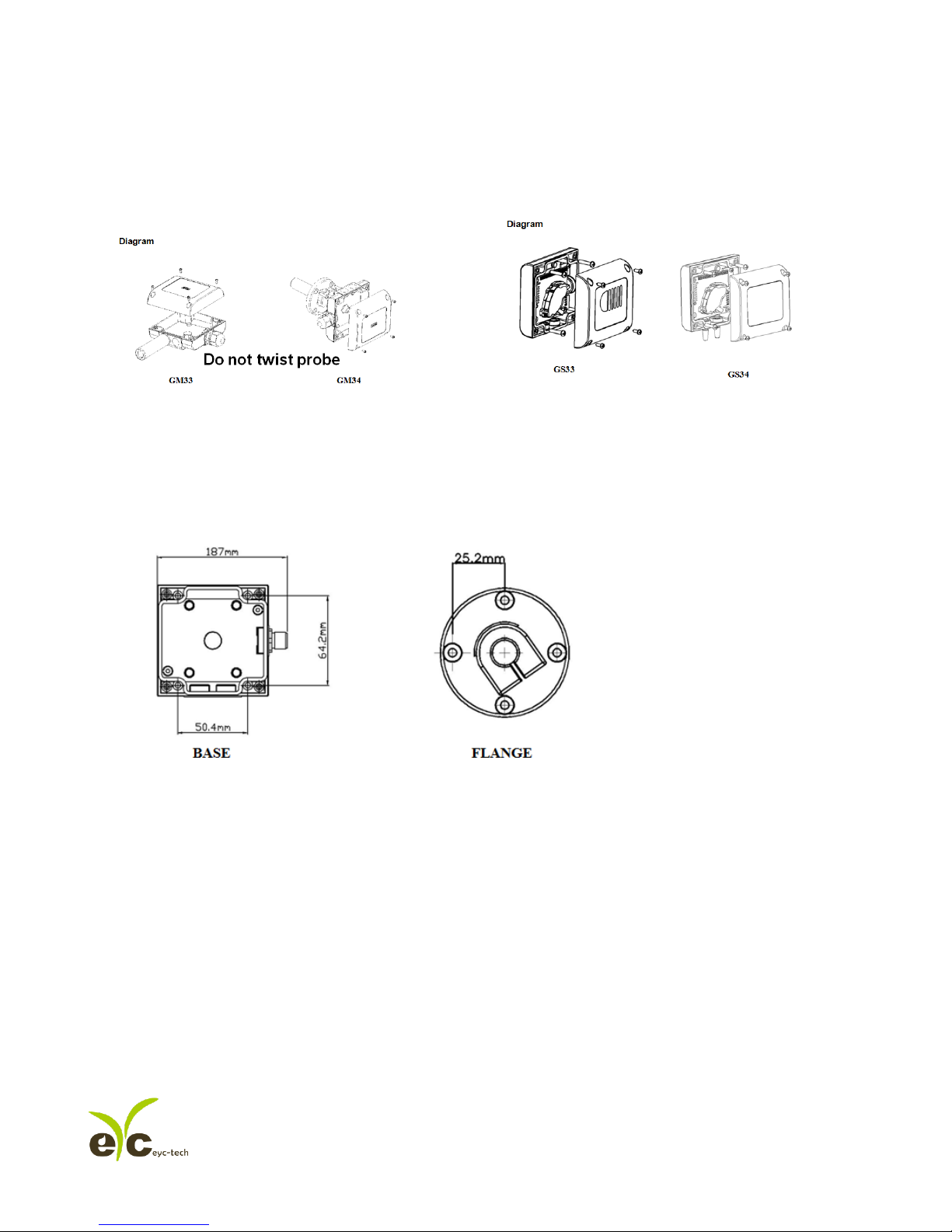
3. Housing, Dimension & Installation
3.1 Housing & Dimension
3.2 Installation
Base
Page 7

Gas monitoring transmitter. Operation manual
PAGE:7 OF 30
Ver:01
4. Hardware Feature
Power: DC 8~35V or AC 12~30V (under current consumption 300mA)
Analog output: Two independent channel, Optional 0~1V, 0~5V, 0~10V, 1~5V, 0~20mA, 4~20mA
RS-485 output: Baud Rate 9600, 19200, 38400, 57600, 115200 bps
Data Frame N81, none parity, 8 bit data, 1 bit stop
Station ID 1-247
Page 8
Gas monitoring transmitter. Operation manual
PAGE:8 OF 30
Ver:01
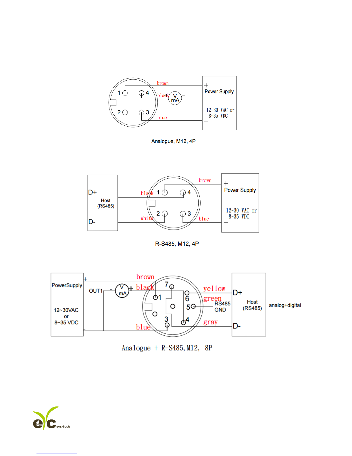
5. Signal Connection
1. Analog Output Connection Diagram
2. RS-485 Serial Port Connection Diagram
3. Analog Output and RS-485 Serial Port Connection Diagram
Page 9

Gas monitoring transmitter. Operation manual
PAGE:9 OF 30
Ver:01
6. Software Feature & Using
6.1 Software Compatibility
Software features are compatible to Microsoft Windows System, and the PC System connects with
GM/GS product via COM PORT (Serial Port)。
6.2 RS-485 Serial Communication
GM/GS product uses RS-485 Serial Port Interface to connect with monitor PC, except the software, the
hardware interface is also necessary, GM/GS PRODUCT provides 2 methods for hardware connection.
1. If the PC equipped with COM Port. Use Converter (RS-232 to RS-485) to connect with GM/GS
PRODUCT .
2. In despite of the PC equipped with COM Port. Use Converter (USB to RS-485) to connect with GM/GS
PRODUCT .
6.3 GM/GS PRODUCT Setting_Analog Output
1. User can set the different output voltage or electric current range independently on each terminal as
0-1V, 0-5V, 1-5V、0-10V ,2-10V, 0-20mA or 4-20mA.
Page 10

Gas monitoring transmitter. Operation manual
PAGE:10 OF 30
Ver:01
6.4 GS PRODUCT Setting_CO2 Self-Correcting Algorithm ADC
1. NDIR is a fast, accuracy & precious technology to detect CO2 concentration. It uses two physical
characteristics, to detect the concentration of specified gas,
a. The gas absorbs the wavelength of Infrared Rays.
b. The gas concentration and absorbed quantity is Direct Proportion.
2. The strength of Infrared Rays have attenuation phenomenon after long time, Then the accuracy &
precious of measurement must be influenced. Thus the technology of CO2 Self-Correcting Algorithm
provides improvement for this defection.
3. In the general environment, the CO2 concentration usually measured as 400ppm. The environments as
From Room/ Office with the condition as midnight period & nobody status, the CO2 concentration
usually measured as 400ppm. Thus GS use the average statistics values for 7 days to implement
Self-Correcting feature.
4. This feature is not adaptive to use in special environment as Factory/ Plant Greenroom where the CO2
concentration may keep on high value & keep for long period.
6.5 GM/GS PRODUCT Setting_Port No. & Transmission Rate
1. RS-485 serial communication interface merged with Modbus Protocol, these 2 features co-works to
construct the digital communication format.
2. Usable Port No. Range : 1~247.
3. On the same wiring, the Port No. must to be different.
4. The maximum devices quantity which connected to RS-485 interface restricted on 31 devices.
5. Three selectable Transmission Rate (Baud Rate): 9600 / 19200 / 38400 / 57600 / 115200 bps.
Page 11

Gas monitoring transmitter. Operation manual
PAGE:11 OF 30
Ver:01
7. GM/GS PRODUCT UI operation step
7.1 Execute “GTH UI” ..................................................................................................................... 12
7.2 Connect to PC via RS-485 ........................................................................................................ 13
7.3 Scan RS-485 connection .......................................................................................................... 16
7.4 Setting RS-485 communication format ..................................................................................... 21
7.5 Select Parameter of Output ...................................................................................................... 23
7.6 CO2 Self-Correcting ADC ......................................................................................................... 25
Page 12
Gas monitoring transmitter. Operation manual
PAGE:12 OF 30
Ver:01
7.1 Execute “GTH UI”
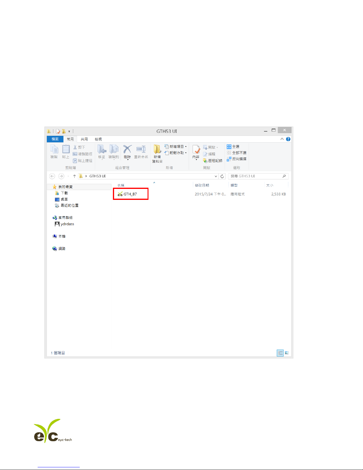
1. Free installation file:GTH_XX.exe
a. O.S Requirement: Windows XP or above.
b. Click “GTH_B7.exe” to open GTH UI
2. Other applications required: Microsoft Office 2003 or above
Page 13
Gas monitoring transmitter. Operation manual
PAGE:13 OF 30
Ver:01
7.2 Connect to PC via RS-485
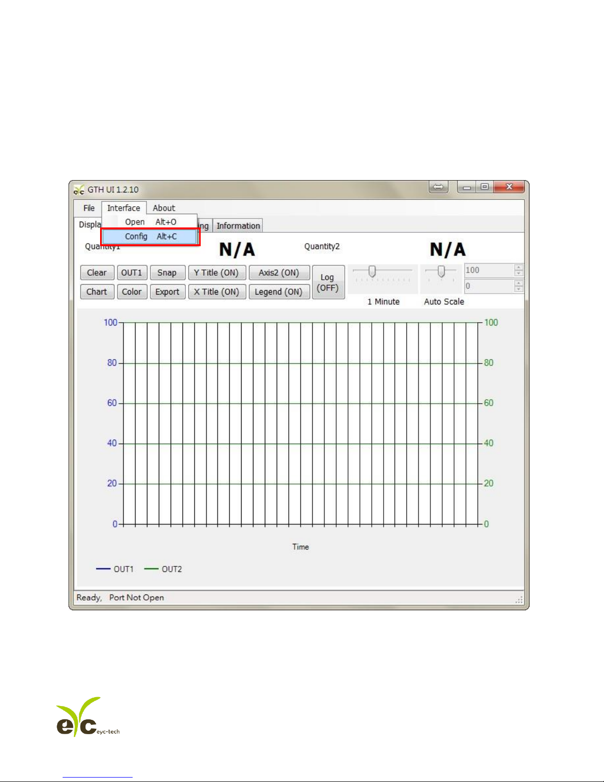
1. Connect GM/GS PRODUCT to PC via RS-485 cable
2. Click“Interface > Config”
Page 14
Gas monitoring transmitter. Operation manual
PAGE:14 OF 30
Ver:01
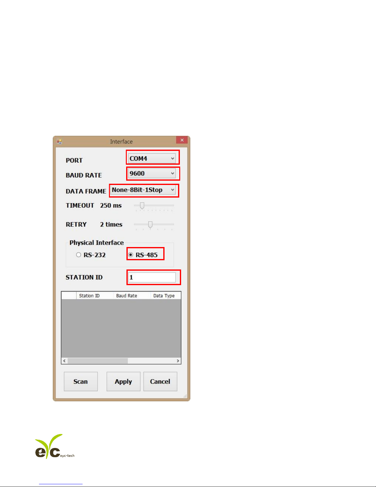
3. Select the corresponding values of com port as following :
a. Port No
b. Baud Rate:9600, 19200, 38400, 57600, 115200
c. Data Frame:None-8Bit-1Stop, None-8Bit-2Stop, Even-8Bit-1Stop, Even-8Bit-2Stop,
Odd-8Bit-1Stop, Odd-8Bit-2Stop,
d. Physical Interface: RS-485
e. Station ID(The factory default 1)
4. Click Apply accomplish the setting
a.
d.
e.
b.
c.
Page 15
Gas monitoring transmitter. Operation manual
PAGE:15 OF 30
Ver:01
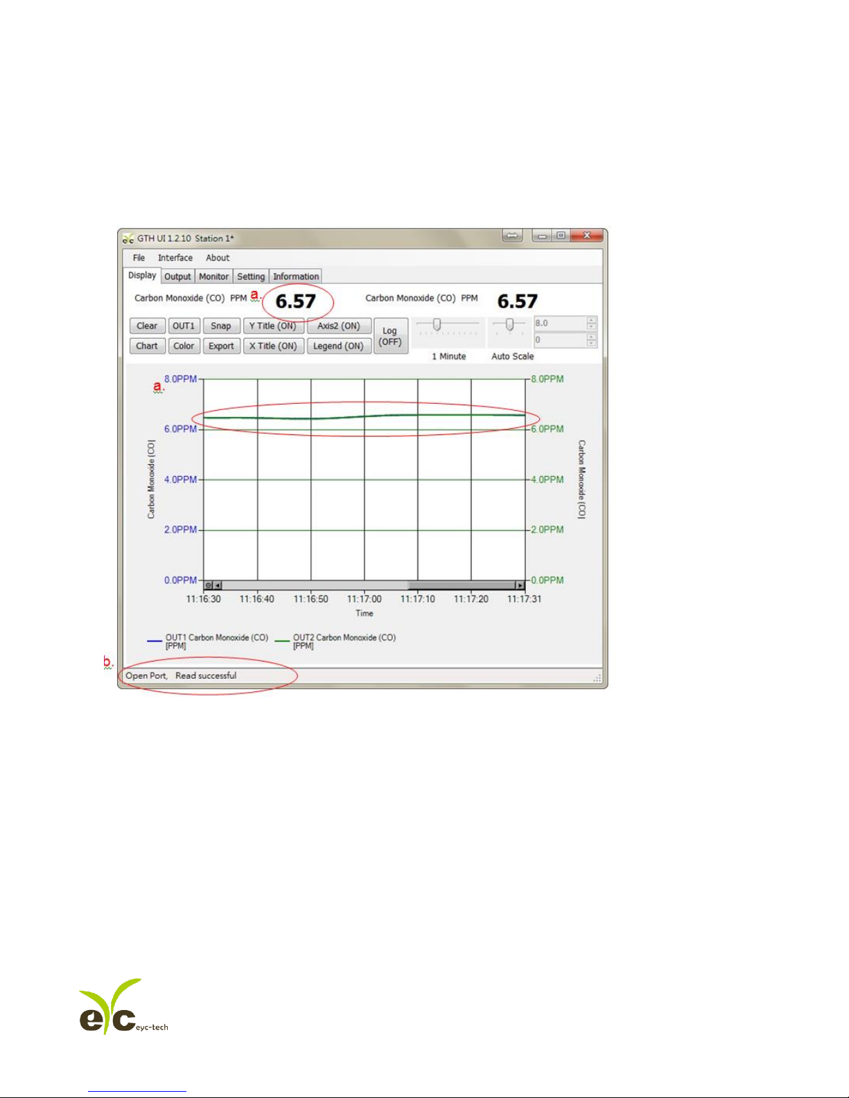
5. Connect successful:
a. Shows the values of output
b. Shows “Open port, Read successful” in status bar
.
.
Page 16
Gas monitoring transmitter. Operation manual
PAGE:16 OF 30
Ver:01
7.3 Scan RS-485 connection
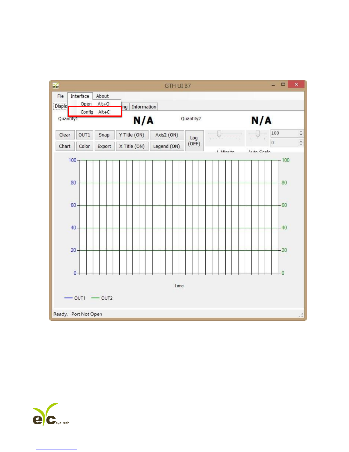
1. Connect PRODUCT to PC via RS-485 cable
2. Click“Interface > Config”
Page 17
Gas monitoring transmitter. Operation manual
PAGE:17 OF 30
Ver:01
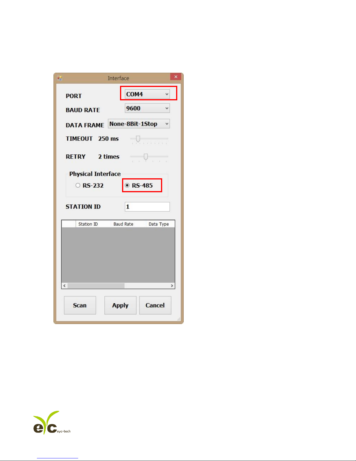
3. Select the corresponding values of com port as following
a. Port
b. Physical Interface: RS-485
4. Click Scan to start connection device scans
a.
b.
Page 18
Gas monitoring transmitter. Operation manual
PAGE:18 OF 30
Ver:01
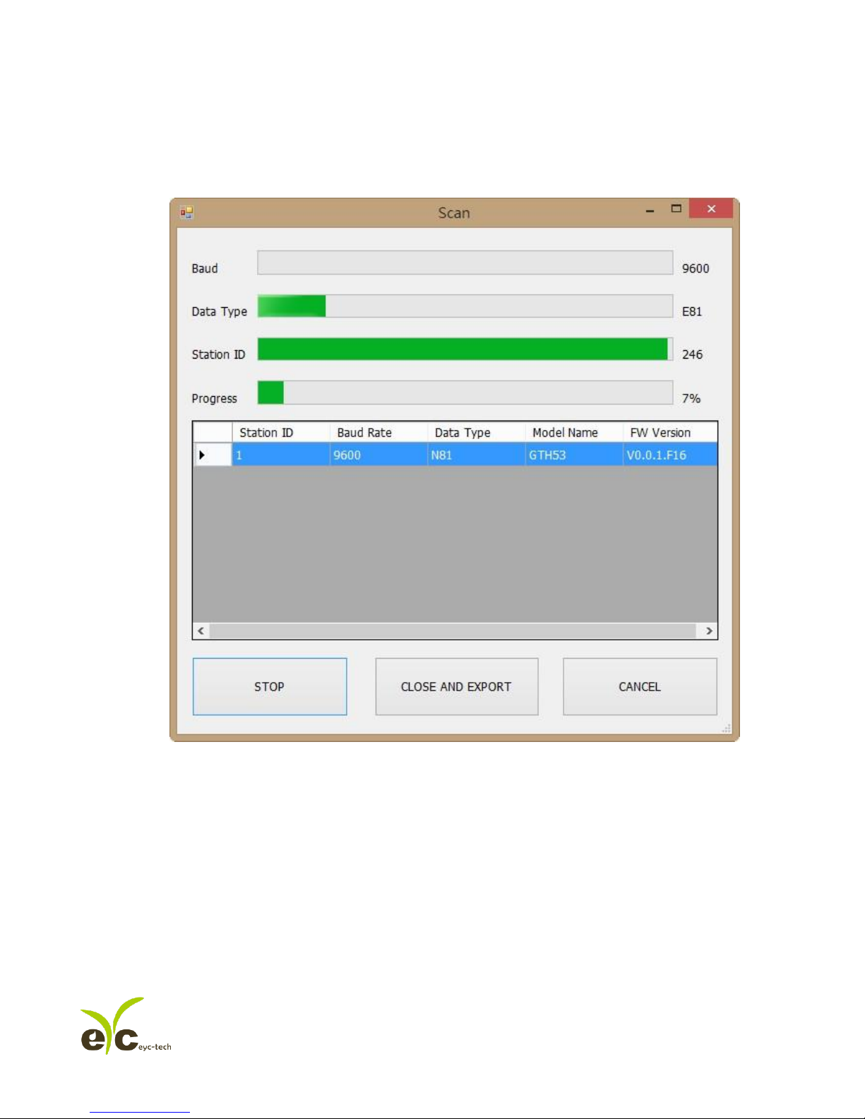
5. Scanning device and setting state
a. Choose Station ID
b. Click CLOSE AND EXPORT
a.
b.
Page 19
Gas monitoring transmitter. Operation manual
PAGE:19 OF 30
Ver:01
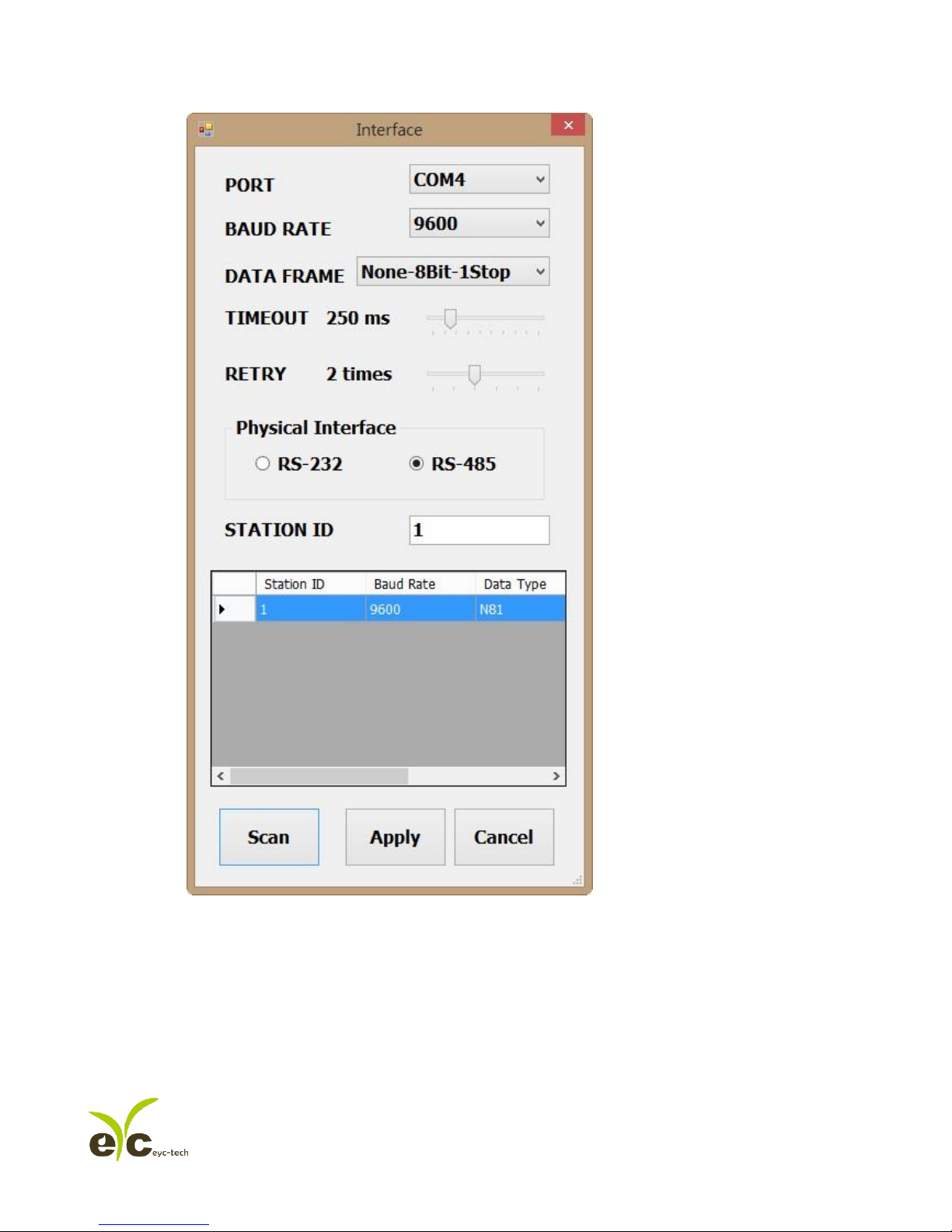
6. Click Apply accomplish the setting
Page 20
Gas monitoring transmitter. Operation manual
PAGE:20 OF 30
Ver:01
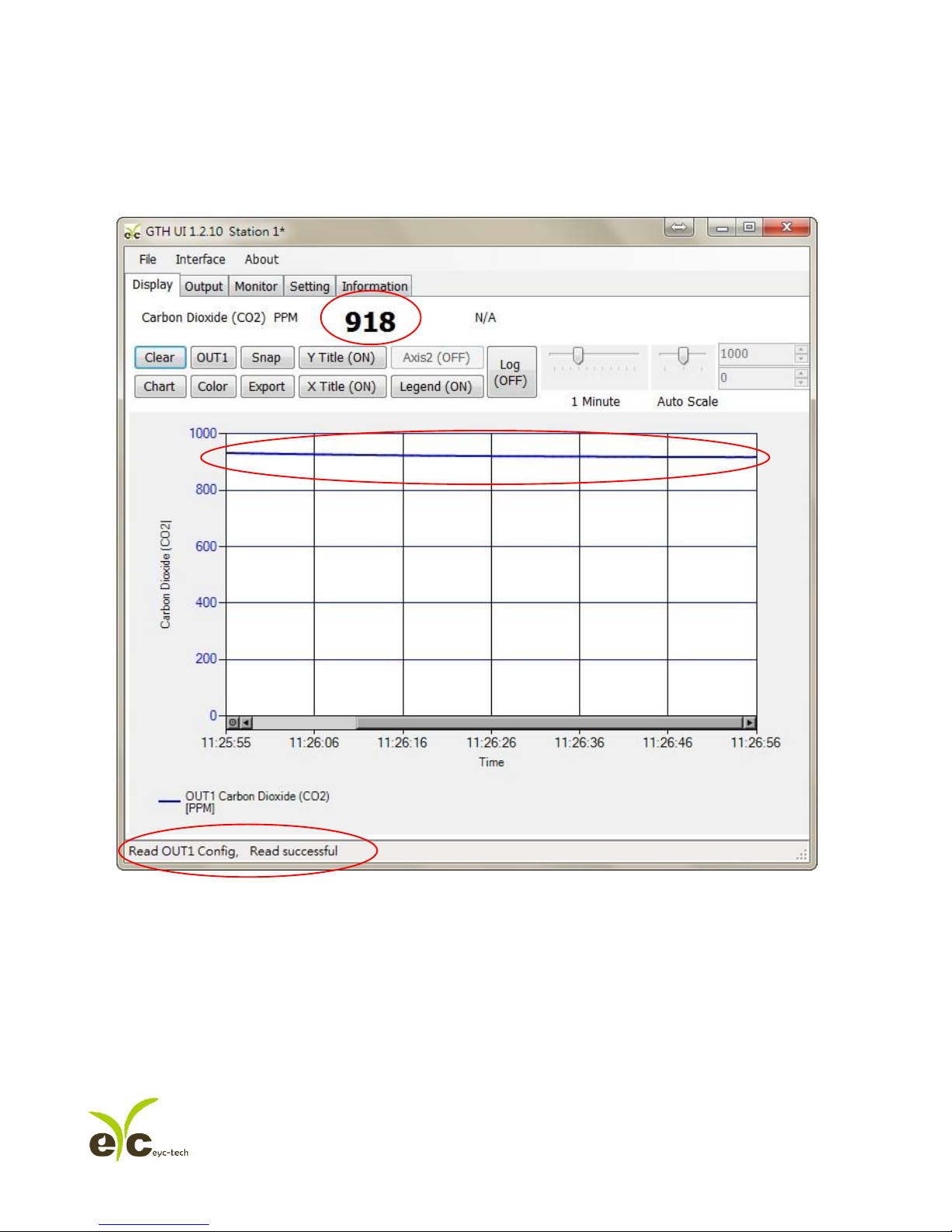
7. Connect successful
a. Shows the values of output
b. Shows “Read OUT1 Config, Read successful” in status bar
a.
a.
b.
Page 21
Gas monitoring transmitter. Operation manual
PAGE:21 OF 30
Ver:01
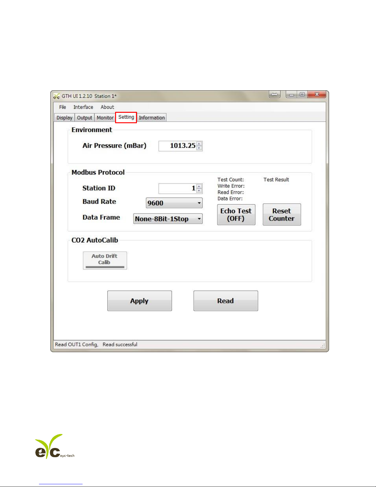
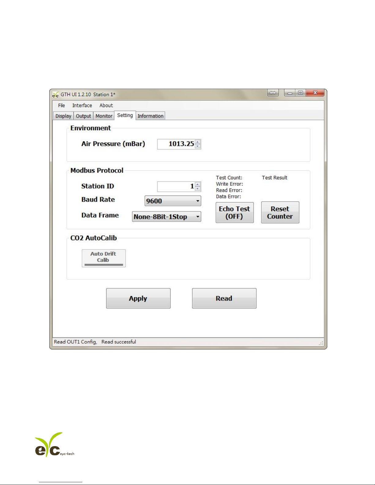
7.4 Setting RS-485 communication format
1. RS485 connection establishment according to 7.2
2. Click on Setting
Page 22
Gas monitoring transmitter. Operation manual
PAGE:22 OF 30
Ver:01
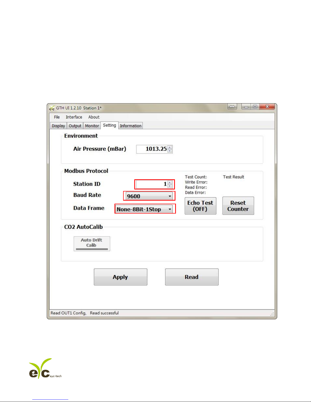
3. TO select Modbus Protocol paramter
a. Station ID:1~247
b. Baud Rate:9600, 19200, 38400, 57600, 115200
c. Data Frame:None-8Bit-1Stop, None-8Bit-2Stop, Even-8Bit-1Stop, Even-8Bit-2Stop,
Odd-8Bit-1Stop, Odd-8Bit-1Stop
4. Click Apply accomplish the setting
5. RS485 connection establishment according to 7.2 or 7.3
a.
b.
c.
Page 23
Gas monitoring transmitter. Operation manual
PAGE:23 OF 30
Ver:01
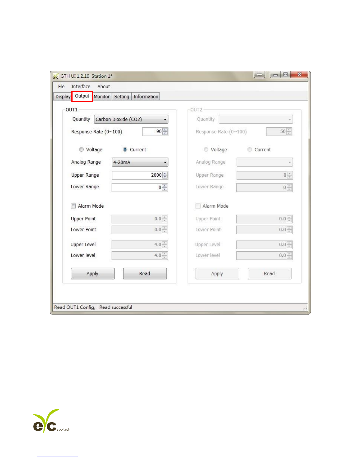
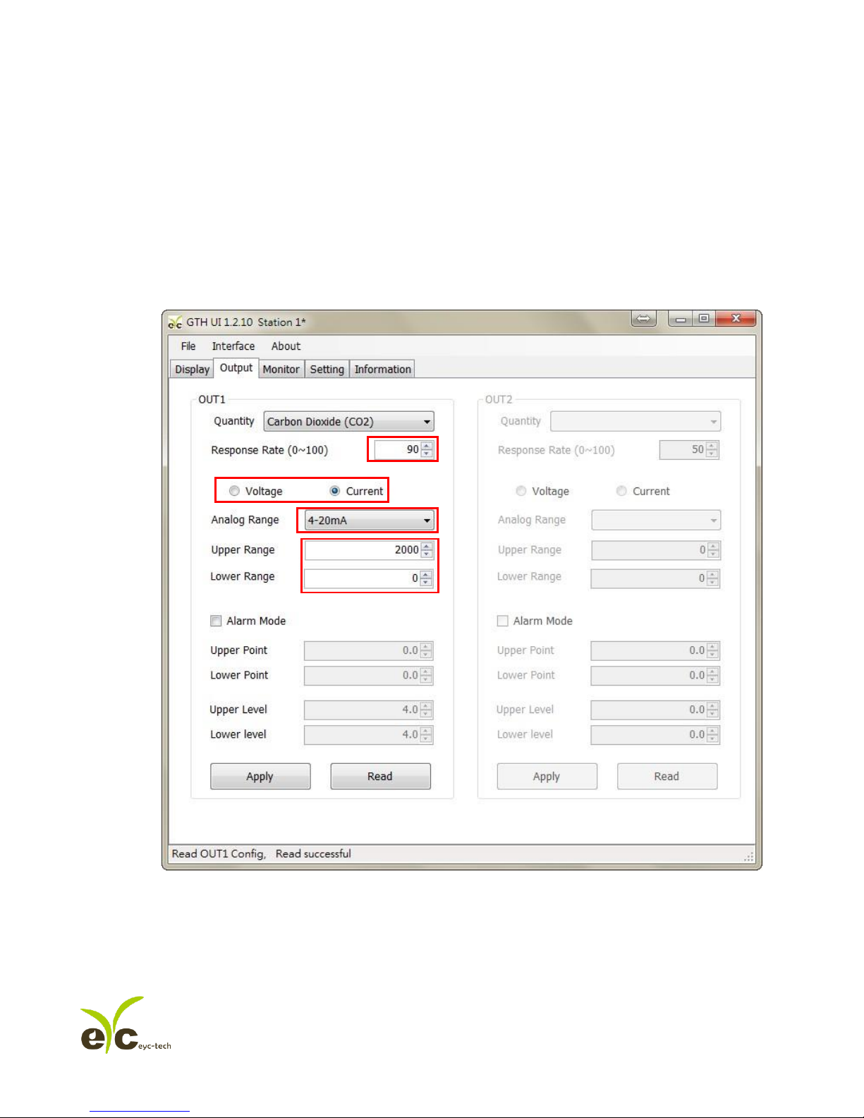
7.5 Select Parameter of Output
1. Click on Output
Page 24
Gas monitoring transmitter. Operation manual
PAGE:24 OF 30
Ver:01
2. Select the parameters of Output1 and Output2
a. Response Rate
b. Analog output: Voltage or Current
c. Analog Range
d. Upper Point and Lower Range
3. Click Apply accomplish the setting
a.
b.
c.
d.
Page 25
Gas monitoring transmitter. Operation manual
PAGE:25 OF 30
Ver:01
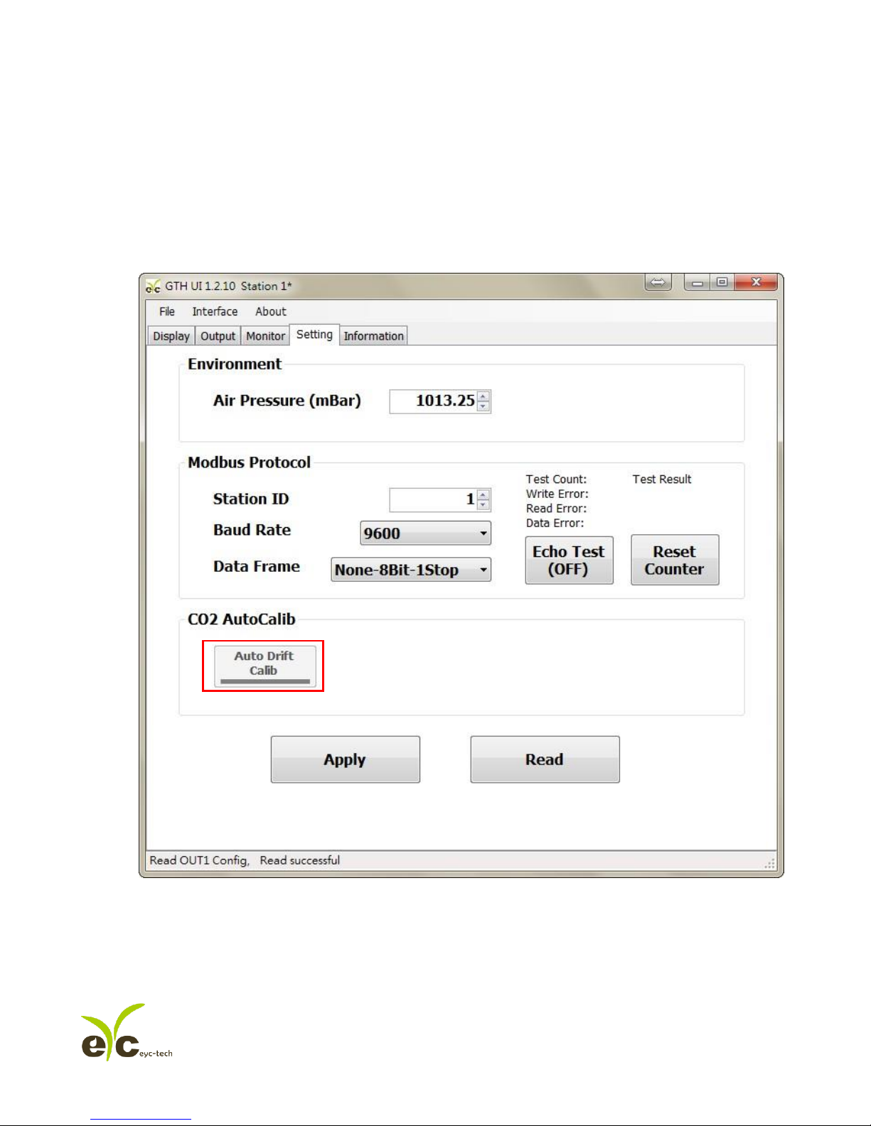
7.6 CO2 Self-Correcting ADC
1. RS485 connection establishment according to 7.2
2. Click on Setting
Page 26
Gas monitoring transmitter. Operation manual
PAGE:26 OF 30
Ver:01
3. CO2 AutoCalib > Auto Drift Calib:The default status set as OFF, this function is used for calibration
of CO2 environment, it perform the sampling method (average value of 7 days) to implement
calibration.
a. This product is suitable for indoor HAVC environment as general apartment, office building.
b. The environment have to clean up for over 6 hours if user attempt to turn ON this function; And
it is advised to turn OFF this function if the humans stay in the indoor environment for long
periods.
Page 27

Gas monitoring transmitter. Operation manual
PAGE:27 OF 30
Ver:01
8. Protocol
8.1 User can use GTH UI to read data, and another option as ModBus Protocol is provided.
8.2 Modbus is a standard protocol in industry field, a common protocol between electrical equipments.
8.3 For getting more information, please refer to the protocol of GM/GS PRODUCT product.
8.4 Wiring Rule:
1. The Port No. must be different.
2. The maximum devices which connected to RS-485 interface restricted to 32 devices.
3. Transmission Rate (Baud Rate) must be the same.
Page 28

Gas monitoring transmitter. Operation manual
PAGE:28 OF 30
Ver:01
9. Factory Default Setting
9.1 Suggested Setting
Please refer to following setting details if user does not assign any feature,
1. ID Setting : 01
2. Modbus Baud Rate : 9600
3. Analog Output : 4-20mA
4. CO2 Range : 0-5000 PPM
5. CO Range : 0-100 PPM
6. CO2 Self-Correcting ADC : OFF
Page 29

Gas monitoring transmitter. Operation manual
PAGE:29 OF 30
Ver:01
10. Cautions
10.1 In order to prevent the internal PCB & Electric Components from damages, the user must be careful
while opening the cover.
10.2 In order to avoid damage or measuring error, for anybody, do not touch or knock the
High-Sensitivity Sensors.
10.3 In order to maintain accurate measuring values. Please install product at well ventilation location.
10.4 For the special environment as Chemical Factory or Plant Greenhouse, please turn OFF the CO2
Self-Correcting ADC function if the CO2 concentration stays on long term & high concentration
status.
Page 30

Gas monitoring transmitter. Operation manual
PAGE:30 OF 30
Ver:01
11. Inspection and Maintenance
Maintenance & Trouble Shooting
The user is unnecessary to calibrate the product while installation. The GTH03 product has already
accomplish the inspection/ calibration before shipment. The user just to follow the steps for maintenance.
1. Periodical Inspection --- According to the contamination status & density of air dust, to implement the
inspection/ maintenance periodically for sensing accuracy, and clean the filter of GTH03.
2. Protection for High-Sensitivity Sensor --- In order to protect the surface of sensor, any scratch/ damage is
forbidden during the maintenance.
3. Trouble Shooting --- Please follow the instructions for appropriate solution,
Unusual Status
Inspection
Shooting Procedure
1. No Output
2. Output Unstable
1. Disconnected Wiring.
2. Wiring Loosen or Disconnected.
3. Confirm the voltage of power
supply.
4. The damage of sensors.
1. Re-Perform the wiring
2. Crew on terminal tightly or
re-place wires.
3. Replace the sensor.
1. Slow Response Output
2. Inaccuracy
1. Moisture/ Condensation on sensor.
2. Check the installed location.
3. Check the dust & Contamination of
GTH03 Housing.
1. Remove the housing.
2. Place the sensor in the Clean/
Nature Air for drying.
3. Refer to the Chapter 5 for
installation.
4. Clean the filter of GS/GM
 Loading...