

Vehicle training equipment
User’s guide for DTM7000
Set of 9 training modules:
LIGHTING & SIGNALLING SYSTEMS

DTM7000
2
Doc.: 00293978-v1
CONTENT
1. INSTALLATION GUIDE .......................................................................................... 3
Installing and setting-up all DTM7000 modules ...................................................................................................... 3
Operational environment ......................................................................................................................................... 3
Calibration & maintenance of all DTM7000 modules ............................................................................................. 3
Number of stations, user position ........................................................................................................................... 3
Method for removal from service ............................................................................................................................ 3
Residual hazards .................................................................................................................................................... 3
2. THE BASICS OF ELECTRICITY ............................................................................ 4
Reminder of the Basics of Electricity ...................................................................................................................... 4
Physical laws........................................................................................................................................................... 4
Equipment to be used ............................................................................................................................................. 4
Vehicle power supply .............................................................................................................................................. 6
Standardised terminal IDs (taken from DIN 72 552) ............................................................................................... 6
Connections ............................................................................................................................................................ 6
Electrical circuit components .................................................................................................................................. 8
Fuse ........................................................................................................................................................................ 9
Diodes ................................................................................................................................................................... 10
Transistors ............................................................................................................................................................ 10
Consumers ............................................................................................................................................................ 12
Relays ................................................................................................................................................................... 12
3. DETAILS OF THE DTM7000 SERIES OF MODULES ......................................... 13
Module DTM7001D ............................................................................................................................................... 13
Module DTM7001G: .............................................................................................................................................. 13
Module DTM7002D ............................................................................................................................................... 14
Module DTM7002G ............................................................................................................................................... 14
Module DTM7003 ................................................................................................................................................. 15
Module DTM7004 ................................................................................................................................................. 15
Module DTM7005 ................................................................................................................................................. 16
Module DTM7006 ................................................................................................................................................. 16
Module DTM7007 ................................................................................................................................................. 17
Module DTM7008: ................................................................................................................................................ 18
4. WIRING EXAMPLES ............................................................................................ 19
Wiring example: indicator lights ............................................................................................................................ 19
Wiring example: indicators and hazard warning lights ......................................................................................... 20
Determining fuse calibres and cross sectional areas of wiring ............................................................................. 21
Wiring for side lights & dipped beams with a relay ............................................................................................... 22
Wiring diagram ...................................................................................................................................................... 24
Acquisition & Comments ....................................................................................................................................... 25

Lighting & Signalling modules
3
Site: exxotest.com
1. INSTALLATION GUIDE
Installing and setting-up all DTM7000 modules
Connect to a 12 to 14 V power supply (not provided), paying careful attention to polarities.
Then interconnect the various modules in accordance with the operating manual supplied with all
DTM7000 modules.
Then energised, moving parts remain in their current position.
Operational environment
All DTM7000 modules should be installed in a clean, dry location, free of dust, water vapour and
combustion fumes.
The equipment requires a lighting level of approximately 400 to 500 Lux.
The equipment can be installed in a Practical Workshop Classroom, the noise generated will not exceed
70 dBA.
Modules are protected from potential user errors.
Calibration & maintenance of all DTM7000 modules
Calibration: Factory Settings.
Servicing interval: N/A
Cleaning: Use a soft, clean cloth with a window cleaning product.
Number of stations, user position
All DTM7000 modules can be taken as one single workstation.
The various modules are placed on a worktop, and users will remain seated throughout their practical
lesson.
Method for removal from service
Turn off power supply, unplug all connecting wires. Check for current by pressing the buttons on each
module, if nothing happens, no current is present.
Then store the DTM7030 modules in a contained room with a panel marked "Equipment Removed from
Service".
Residual hazards
After extended use of the bulb unit there is a risk of burns.

DTM7000
4
Doc.: 00293978-v1
2. THE BASICS OF ELECTRICITY
Reminder of the Basics of Electricity
Voltage. The Volt is used to measure Voltage (also known as 'potential difference' or 'pd), which is
defined as the work done per unit charge in order to move that charge from one point to another. The
symbol used for voltage is V, and its unit is the Volt.
Current. The Amp (or Ampere) is used to measure an electrical current, which is defined as the rate of
flow of electrical charges through a point per second. The symbol used for current is I, and its unit is the
Ampere.
Resistance. The Ohm is used to measure electrical resistance, which is defined as the opposing force
applied, by a component, to the electrical charges in a circulating current. The symbol used for
resistance is R and its unit is the Ohm (Ω).
Physical laws
In an electrical circuit, the flow of current is controlled by the following two rules:
The lower the resistance, the greater the current flowing through the circuit.
The higher the voltage, the higher the current flowing through a fixed resistance.
These two rules allow us to form fundamental Ohms laws:
U=I*R where U is expressed in Volts, R in Ohms & I is in Amperes.
Power is defined by a mathematical formula:
P=I*U where P is expressed in Watts, U in Volts & I in Amperes.
Equipment to be used
The Voltmeter used to measure a voltage or potential difference across the terminals of a component in
an electrical circuit. The following precautions must be taken during use:
The voltmeter must be connected in parallel with the terminals of the component to be tested.
The Ammeter used to measure the current flowing through a circuit. The following precautions must be
taken during use:
Always connect to the circuit to be tested in series.
Must be associated with a load.
Pay careful attention to the maximum authorised current for the ammeter in use.
Lighting & Signalling modules
5
Site: exxotest.com
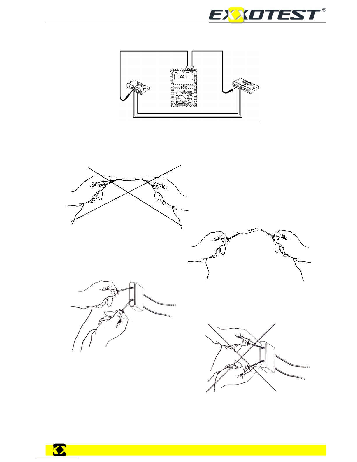
The Ohmmeter used to measure the resistance of a conductor. Connects to the terminals of the
component to be tested.
The following precautions must be taken during use:
The device should never be connected to an external power supply.
Components to be measured must be disconnected from the circuit and powered-down.
Avoid disrupting readings by touching the circuit with any part of your body (which is a conductor).
DTM7000
6
Doc.: 00293978-v1
Vehicle power supply
Vehicles are fitted with batteries, which work as chemical storage devices for the electrical energy
produced by the vehicle's generator (alternator). The batteries must be capable of providing rapid high
current supplies (above all, at low temperatures) when starting the vehicle cold and providing partial or
total supply to the other major loads throughout the vehicle's electrical system for a limited period, above
all when the vehicle's engine is running at idle or has been stopped. This requirement is generally met by
a lead-acid battery (sulphuric acid).
The normal voltage for a battery fitted to a private vehicle is 12V.
The requirements imposed by each of the vehicle's circuits, in terms of starting power, capacity and
charging current, apply for a temperature range of between -30 and +70 °C.
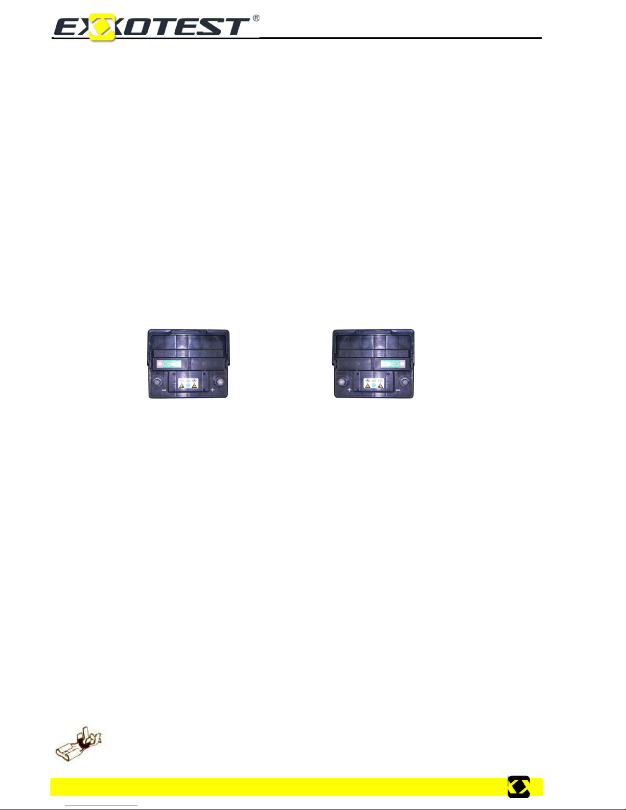
The various characteristics of vehicle batteries:
Voltage - generally 12.5 V for private vehicles.
Capacity, in Ah (Ampere-Hours), i.e. the number of amps which can be consumed for a period of
one hour before the battery is fully discharged (Caution: with a half-charged battery, it may prove
difficult to start the vehicle).
The number of amps supplied at start-up - depending on vehicle type and engine.
The size and height - different for each vehicle.
Location of positive and 0 V terminals.
Standardised terminal IDs (taken from DIN 72 552)
A few examples of markings:
1 Ignition - low voltage
15 Positive when ignition is turned on
Battery Starter
30 + Battery 50 Starter motor control
31 Ground 0v
Relays
85 & 86 Relay control 87 Working
87b At rest 30 Common
Connections
Definition:
Connections are used to link two or more components, with the option of disconnecting the link,
maintaining a good electrical contact and even waterproofing the connection.
Several different types of shapes exist, all of which are easy to remove.
The best connections are those with the lowest possible electrical resistance.
Be aware of current restrictions!
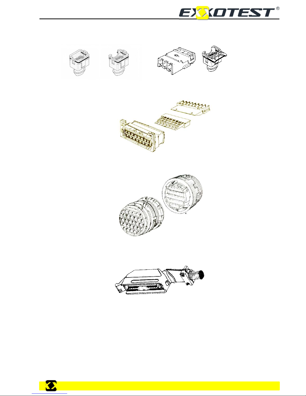
Examples of types of connector:
Female flat-lugged connector.
3-way female flat-lugged connector.
+ 0V 0V +
Lighting & Signalling modules
7
Site: exxotest.com
Female, 1-7-way connector with or without clip, leak tight (water temperature probe, HV coil,
etc. used by PSA and Renault):
Female connector, 9, 15... way, leak tight (powered ventilation control unit, etc., used by PSA).
Bulkhead connector, 10, 14, 23, way, leak tight (used by PSA):
15, 25, 35, 55, way connector, for all types of ECU: injection, ABS, air conditioning, suspension
control, etc. on a number of vehicles.

DTM7000
8
Doc.: 00293978-v1
Electrical circuit components
Connecting multi-strand copper wires of various cross-sections, depending on current.
The resistance within the circuit depends on:
Length:
Cross section (flow):
Type of cable:
Lighting & Signalling modules
9
Site: exxotest.com
Table of standard values for electrical conductors:
Conductor
Resistivity in Ω.m
Silver 1,64 .10-8
Copper 1,72 .10-8
Aluminium 2,69 .10-8
Nickel 7,8 .10-8
Iron 9,8 .10-8
Chrome-plated nickel 108,5 .10-8
Table showing resistance and weight of copper wiring:
Diameter
mm
Cross section
mm
2
Weight
kg/km
Weight
kg/km
1,00 0,7854 7 22,28
1,50 1,7671 15,750 9,903
2 3,142 28,00 5,570
2,5 4,909 43,75 3,565
3 7,069 63 2,476
Fuse
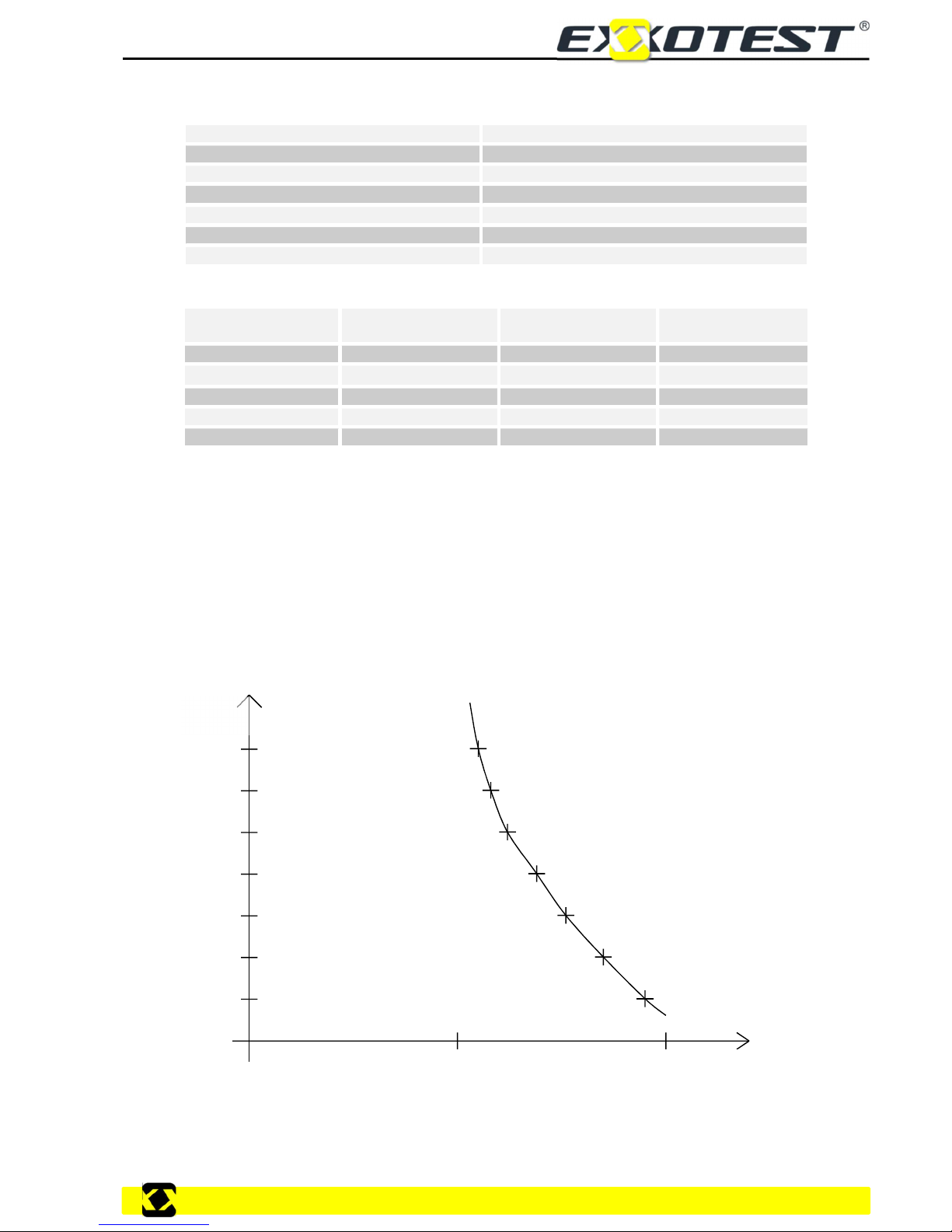
A fuse is a safety device, used to protect an electrical circuit from excess current. Generally, fuses
comprise a metal strip which melts at a given temperature. If the current flowing through the circuit
exceeds a pre-determined value, the fuse metal melts, thus opening the circuit.
A 10A fuse is designed to withstand 10 Amperes at 20°C; however, it will withstand 20A for a period of
10 seconds, 30A for 5 seconds and even 80A for 0.01 seconds.
Here is an example of the time/current curve for a fast blow 10A fuse (time-delayed fuses are also
available).
Example of a graph:
Example of curve:
1
10
3
10
2
10
1
10
-2
10
-3
10
-1
10 100
1
A
T (s)

DTM7000
10
Doc.: 00293978-v1
B
C E
+ -
-
C B E
- + -
Diodes
They are members of the semi-conductor family and are used to let current flow in one direction whilst
blocking it in the other.
The graphical symbol used for the diode is:
The arrow shows the direction in which current may flow.
Current flows
Current cannot flow
The use of diodes is not restricted to electronic circuits, they can often be found in classical electrical
circuits (e.g.: alternators).
Zener diodes
Take a standard diode. If one applies too high a voltage in the opposite direction the diode will let current
pass, but this will damage it, rendering it unusable.
However, the Zener diode will permit voltages above a certain level to pass through it in the opposite
direction without breaking.
Symbol:
The Zener diode can be found in a wide range of circuits, notably for voltage regulation, load voltage
regulators, etc.
Transistors
Members of the semi-conductor family (germanium, silicon, etc.) and can generally be taken as relays.
There are two groups of transistors, as follows:
Type PNP:
For these transistors to allow current to pass:
The flow of the control current should be from the emitter towards the base
The flow of the current should be from the emitter towards the collector.

Lighting & Signalling modules
11
Site: exxotest.com
B
C E
+
L.E.D.
Type NPN
For the transistor to allow current to pass
The flow of the control current should be from the base to the emitter
The flow of the current should be from the collector to the emitter
The advantages of transistors:
- Can be controlled by a frequency of several megahertz
- Practically indestructible
- No induced currents
- Very low control current from emitter to base
- Instant disconnection
- Can be used as an amplifier
- Noiseless
Each transistor is characterised by its gain. This is a
coefficient which is used to determine the level of
current flowing through the power circuit, from emitter
to collector, based upon the current in the control
circuit, from emitter to base.
E.g.: for a gain of 100, if IEB= 0.1 A, then I
EC
will be 10A.
The transistor does not allow current to flow.
The transistor allows current to flow
B
E C
+ -
+
E B C + + -
B C E
+
L.E.D.

DTM7000
12
Doc.: 00293978-v1
The transistor does not allow current to flow (blocked)
The transistor allows current to flow
Consumers
These are components which consume current. There are two
types of consumer, Active & Passive.
Passive Consumers: bulbs, resistors, etc.
Active Consumers: motors, injectors, retarding valves, etc.
Attention, certain consumers are polarized, whereas others are not.
The notion of Watts Consumed is important when dealing with
consumers, as, for a given voltage one can determine the
absorbed current.
Example of the various modules along with their consumers:
Relays
A relay is made up of two parts, the control circuit and the power circuit.
The control circuit:
You provide a supply of a few milliamps to a coil, which will create a magnetic field.
The power circuit:
The magnetic field created by the control circuit is used to open and close the power circuit, which may
have a current flow of around 10 A.
Within a relay, the control circuit is isolated from the power circuit.
B
C E +
L.E.D.
+
B
C E
+
L.E.D.
+

Lighting & Signalling modules
13
Site: exxotest.com
Example - Module DTM7004 with two relays:
The first relay is a standard, commonly used work/rest relay.
The second is a polarised relay with a 'free-wheeling' diode
designed to protect the control circuits from the induction
effects of the relay coils.
3. DETAILS OF THE DTM7000 SERIES OF MODULES
Module DTM7001D
This module represents the rear lighting cluster on the right hand side and includes the indicator, rear
light, fog lamp and brake light.
Module DTM7001G:
This module represents the rear lighting cluster on the left hand side and includes the indicator, rear
light, reversing light and brake light.
Connection
point for
common earth
Connector terminals
Brake light bulb
Rear R
21W
Fog light bulb
Rear R
21 W
Rear light Rear
R 5W
Indicator bulb
Rear R 21W
Fog lamp bulb
Rear L
21W
Connection point
for common earth
Connector
terminals
Indicator bulb
Rear L
21W
Rear light Rear L
5W
Brake light bulb
Rear L
21W

DTM7000
14
Doc.: 00293978-v1
Module DTM7002D
This module represents the front lighting unit on the right hand side and includes the indicator, side light
and dipped/main beam headlights.
Module DTM7002G
This module represents the front lighting unit on the left hand side and includes the indicator,
side light and dipped/main beam headlights.
Connection point
for common earth
Connector
terminals
Indicator bulb
Front R 21 W
Sidelight bulb
Front R
5 W
Headlamp bulb
Front R
Bulb earth
Connection point
for common earth
Connector
terminals
Headlamp bulb
Front L 40/45 W
Indicator bulb
Front L
21 W
Sidelight bulb
Front L
5 W
Bulb earth

Lighting & Signalling modules
15
Site: exxotest.com
Module DTM7003
This module is a fuse panel, used to protect each of the circuits, dependant on the calibre of the fuse
fitted.
Module DTM7004
This module includes two relays, the first a standard relay, the second a polarised relay fitted with a 'freewheeling' diode.
Connection point
for common earth
(E.g.: Earth)
85 & 86
Control circuit
Power circuit
30: common
87a: rest position
87: active position
Power circuit
30: common
87a: rest position
87: active position
85 & 86
Control circuit
Polarisation diode
Free-wheeling
diode
Input terminal
e.g. for fuse F7
Output terminal
e.g.: for fuse F7
Sockets for fuses

DTM7000
16
Doc.: 00293978-v1
Left-hand relay:
ID Description
Functionalities
85 or 2
86 or 1
Control circuit
If one connects 85 & 86 to positive and 0v respectively, the coil
generates a magnetic field which will, in turn, activate the power
circuit.
30 or 3
87b or 4
87 or 5
At rest
Active
Common Power
circuit
Coil de-energized: Terminal 30 is connected to Terminal 87b (at
rest position)
Coil energized: Terminal 30 is connected to Terminal 87 (at active)
Right hand relay, caution, the control circuit is polarised
ID Description
Functionalities
85 or 2
86 or 1
Control circuit
If one connects terminal 86 to positive and terminal 85 to 0v, the
coil generates a magnetic field which will, in turn, activate the
power circuit.
30 or 3
87b or 4
87 or 5
At rest
Active
Common Power
circuit
Coil de-energized: Terminal 30 is connected to Terminal 87b (at
rest position)
Coil energized: Terminal 30 is connected to Terminal 87 (active)
Module DTM7005
This module represents the instrument panel.
ID Description
ID Description
1 Side lights 5 Rear fog lamp
2 Dipped beams 6 Indicator - LHS
3 Earth 7 Brake lights
4 Main beams 8 Indicator - RHS
Module DTM7006
This module represents the lighting control stem switch, including switches for the side lights, dipped
beams, main beams, rear fog lamp and indicators.
Power supply
battery
Output - Main
beams
Output - Main
beams
Output - rear fog
lamps
Main beam flash
control
Lighting controller sidelights, dipped & main beams
Indicator control
Control for horn
Control for
rear fog lamp
Output - sidelights

Lighting & Signalling modules
17
Site: exxotest.com
The lighting controller has four positions:
1st position: OFF
2nd position: side lights ON
3rd position: dipped beams ON
4th position: main beams ON
ID Description
Functionalities
1 Permanent power supply
2 Output - Main beams Two different controls - main beam flasher control and
lighting controller in position 4
3 Output - Main beams Selector in Position 3
4 Output - Fog lamps Selector in Position 2
5 Output - sidelights Selector in Position 1
8 Horn control input or output Actuates horn control
9 Horn control input or output Actuates horn control
11 Common
12 Indicator - LHS Indicator switch - left
13 Indicator - RHS Indicator switch - right
Module DTM7007
This module represents the hazard warning selector
ID Description
Functionalities
1 Power supply output for flasher unit
(module DTM7008)
Constant supply + APC at rest and battery positive
when active.
2 Power supply + APC + APC
3 Battery supply (+30) Permanent positive
4 Earth connection Earth
7 Supply for Terminal C on Module 7008
(flasher unit)
Control signal from flasher unit module (DTM7008)
8
9
To right & left hand side indicators Hazard warning button pressed
Internal hazard warning repeater light Flashes when the hazard warning switch is pressed.
Power supply
battery
Power supply +
APC
Power output to
flasher unit
Supplied by Terminal C on
Module 7008 (flasher unit)
Internal hazard
warning repeater
Earth
Position A - Off when driving
Position B - Hazard warning ON
To right & left hand
side indicators

DTM7000
18
Doc.: 00293978-v1
Module DTM7008:
This module represents the flasher unit, which actuates the instrument panel repeaters, the internal
hazard warning button and the indicators themselves.
ID
Description Functionalities
positive Unit supply Supply with APC at rest and positive from battery when
active
0v System earth Earth
C Output to Terminal 7 on the
DTM7007
When à current is drawn through terminal C to the DTM7007
a square wave signal will be created.
R Instrument panel repeater light When the hazard warning switch is pressed the instrument
panel indicator is supplied.
Supply to flasher
unit from Terminal 1
on the DTM7007
Output to Terminal
7 on the DTM7007
Instrument panel
repeater light
Instrument panel
trailer repeater light

Lighting & Signalling modules
19
Site: exxotest.com
4. WIRING EXAMPLES
Wiring example: indicator lights
-
+

DTM7000
20
Doc.: 00293978-v1
Wiring example: indicators and hazard warning lights
+-

Lighting & Signalling modules
21
Site: exxotest.com
Determining fuse calibres and cross sectional areas of wiring
Calculate the current absorbed by an indicator bulb:
The standard values are 21W for 12.5 V, giving an absorbed current, per bulb, of 1.68 A under normal
operating conditions.
The consumption of the flasher unit is 2W.
The instrument panel repeaters themselves consume 5W.
Determining the choice of Fuse F7 to protect the hazard warning circuit:
4 x lamps at 21 W, the flasher unit at 2 W and the two lamps with a total of 5 W: giving an overall
current of 7.3 A.
The safety coefficient is 2, giving a fuse rating of 15 A.
Determining the choice of indicator fuse:
2 x lamps at 21 W, the flasher unit at 2W and an instrument panel repeater at 2.5W giving a
current of 3.72 A.
The safety coefficient used is 1.5, meaning a fuse of at least 5.58 A should be used; the next
available fuse is 7.5 A, making the safety coefficient 2.2.
Determining the diameter of the wire for the rear right brake light:
Hypotheses:
The length of the power supply wire is assumed to be three metres (the earth being connected to
the chassis in the immediate vicinity of the brake light) this copper wire has a resistance value
of 1.72x10⁻⁸ per metre.
The indicator bulb consumes 21W at 12.5V.
The maximum tolerated voltage drop is set at 1V.
Calculations:
The current flowing through the circuit is 21/12.5 = 1.68 A
The voltage drop of 1 V forces a maximum resistance of:
U = IR, therefore R = U/I or 1/1.68 = 0.5952.
The resistance of a conductor can be found using the following equation:
R = * L / S
S = ( L ) / R = (3 x 1.72x 10
-8
) / 0.5952 = 8.669x 10⁻⁸ M2 giving 0.9 mm
2
The diameter, as a function of the cross section, is found using the following equation:
S = ( * D2 ) /4
D = ( 4 S / )
0.5
D = (( 4 x 0.9 )/ )
0.5
= 1.07 mm

DTM7000
22
Doc.: 00293978-v1
Wiring for side lights & dipped beams with a relay
+
-

Lighting & Signalling modules
23
Site: exxotest.com
What is a relay?
A relay is an electrically controlled disconnector switch, used to control a power circuit using a lower
current control circuit.
Justify the use of a relay for the main and dipped beam lighting circuits:
The power absorbed by these consumers would lead to the switches and wiring being over dimensioned
for the current levels if the control and power circuits were not separated.
What happens if one adds an additional two 55W driving lights, linked to the existing headlamps
(of 55W) without a separate power circuit?
The current will be doubled; however the power and earth-return circuits are not designed to handle this
power. There will therefore be a drop of voltage through the conductors, leading to heating and a voltage
drop at the consumer terminals, which will not work at their optimum level, with ensuing operational
problems.
Calculations for wire cross-sections:
The aim of this study is to show the cross-section of the wires to be used to connect an additional set of
driving lights, assuming they are to be controlled from a relay in the vicinity of the battery, approximately
1.2m from the right hand light.
The earth from the bulbs will be connected 20 cm from the bulbs, for this reason we can assume the
same cross section as used for the bulb supply.
The characteristics of the bulb: minimal voltage 12.5V
Power absorbed at 12.5V: 55W
Calculate, using the previous method, the cross-section of the supply wire to prevent a voltage
drop of greater than 0.5 V.
I at 12.5V = 4.4A
U = IR therefore R = U/I giving an R
max
= 0.11.
R = * L / S giving S = L / R = 1.87 mm2
S = ( * D2) / 4 giving D = (4 S / )
0.5
= 1.54 mm
The corresponding diameter is 1.54 mm.
What can be deduced from the positioning of the relays?
The position should be chosen to minimalize the length of the power cabling.
Showing the resistance of a wire:
Connect the earths from the bulbs on the DTM7002G&D modules, link to a selector switch for the
parallel bulbs, using wires of 2 mm2, and set up a power supply battery.
Prepare two wires with a different cross section, e.g.: 0.4 mm & 2 mm, with a length of 2 m.
Connect the consumers successively with the two wires after having first connected their terminals to a
voltmeter.

DTM7000
24
Doc.: 00293978-v1
Wiring diagram
The two metre wire is represented by the curved wire; its role is to supply the circuit. At the terminals the
voltmeter measures the voltage across the terminals of the wire.
What happens when a voltage is applied?
The bulbs light and the test conductor heats up.
Carry out a test with each wire, what can be deduced?
The longer and thinner the wire the greater the voltage drop across the terminals.
How does the voltage change once the circuit has been energised?
The voltage reaches a peak then first connected, then decreases over time.
How could one define the resistivity of the wire?
The resistivity of the wire has a positive temperature coefficient.
What impact will this change in resistivity have on the voltage and current in the line?
The voltage across the terminals of the wire reaches a peak when first connected then decreases over
time. The current follows the same curve.
+
-
A

Lighting & Signalling modules
25
Site: exxotest.com
Acquisition & Comments
Take a reading of the battery voltage, the voltage across the wire terminals and the current passing
through it, by means of a Reflet® and MI 25A. Display these readings as curves, recording the data from
the moment of initial energising until the voltage across the wire terminals stabilises.
Examples of measurements taken from smaller cross-section wires:
Second test with an average cross-section wire:

DTM7000
26
Doc.: 00293978-v1
Third test with a large cross-section wire:
Comments on the changing parameters:
On initial energising, the switches let a peak current flow as the lower temperature means a lower
resistance.
At a stable operating temperature both voltage and current stabilise.
The changing voltage across the test wire terminals is inversely proportional to the cross-section of the
wire used but is directly proportional to its length as its resistance is characterised by the following
formula:
R = * L / S

Lighting & Signalling modules
27
Site: exxotest.com
Propose a method for fitting dipped & main beams which causes no operational inconveniences:
+-

DTM7000
28
Doc.: 00293978-v1
Common earth circuits: example of the rear lights fitted to a vehicle
The following diagram shows the wiring for the rear fog lamps and rear lights with the earths for the
bulbs regrouped at a point A.
Wire the circuit and operate it.
Disconnect the rear left hand light from the earth at A and turn on the lights. What happens?
The left hand rear light and fog lamp light up dimly.
Trace the circuit the current is flowing along. What can one deduce from the voltage across the
bulb terminals?
The rear right light and left hand lights are in series, dropping their supply voltage to just 4V.
Turn on the rear lights and fog lamps. What happens?
Only the right hand bulbs light up.
Why?
The two left hand lights are supplied from two positive terminals, making a zero potential difference
across their terminals.
+-
A

Lighting & Signalling modules
29
Site: exxotest.com
DECLARATION OF CONFORMITY
By means of this declaration of conformity, as defined by the European Directive on Electromagnetic
Conformity 2004/108/EC, the company:
Declares that the following product:
Brand
Model
Description
EXXOTEST
DTM7000 model
TRAINING MODEL: automatically controlled vehicle air
conditioning
I - Has been manufactured in accordance with the requirements of the following European
Directives:
4
LV Directive 2006/95/EC - 12 December 2006
Machinery Directive 98/37/EC - 22 June 1998
EMC Directive 2004/108/EC - 15 December 2004
and satisfies the requirements of the following standard:
NF EN 61326-1 dated 07/1997 +A1 of 10/1998 +A2 of 09/2001
Electrical measurement, control and laboratory equipment, EMC-related requirements.
II - Has been manufactured in accordance with the requirements of the European Directives
relating to EEE design and WEEE management for the EU. :
Directive 2002/96/EC dated 27 January 2003 on Waste Electronic and Electrical Equipment
(WEEE)
Directive 2002/95/EC dated 27 January 2003 on the limitations for the use of certain hazardous
substances in the construction of Electronic and Electrical Equipment (EEE).
Drawn up in Saint-Jorioz on 12 December 2011.
CEO - Stéphane SORLIN
ANNECY ELECTRONIQUE S.A.S.
Parc Altaïs – 1, rue Callisto
F-74650 CHAVANOD
 Loading...