

EXXOTEST DLC-MUXDIAG-II, DLO-MUXDIAG-II User Manual

Web : www.exxotest.com Document n° 00283735-v1
ANNECY ELECTRONIQUE, créateur et fabricant de matériel : Exxotest, Navylec et Aircraft Electronic.
Parc Altaïs - 1 rue Callisto - F 74650 CHAVANOD - Tel : 33 (0)4 50 02 34 34 Fax : 33 (0)4 50 68 58 93
S.A.S. au Capital de 276 000€ - RC ANNECY 80 B 243 - SIRET 320 140 619 00042 - APE 2651B - N° TVA FR 37 320 140 619
Certificat ISO 9001 : 2008 N° FQA 4000142 par L.R.Q.A.
DLx-MUXDIAG-II – User guide
Communication interface with
autonomous datalogger function
DLC-MUXDIAG-II / DLO-MUXDIAG-II
User guide

USB-MUXDIAG-II – User guide
16/05/2012 00283735-v1 2
Document confidentiel appartenant à Annecy Electronique S.A.S.
Ne peut être diffusé, copié intégralement ou en partie sans autorisation expresse préalable
SUMMARY
1. Document’s purpose and bibliography ....................................................... 4
1.1.1. Purpose ............................................................................................................... 4
1.1.2. Bibliography........................................................................................................ 4
2. Presentation .............................................................................................. 5
2.1.1. General presentation ......................................................................................... 5
2.1.2. Synoptic .............................................................................................................. 6
2.1.3. Main characteristics of the CAN channel ........................................................... 6
2.1.4. Protocol controller: INFINEON TWINCAN .......................................................... 6
2.1.5. High speed line interface: PHILIPS PCA82C251 .................................................. 6
2.1.6. Low speed line interface: PHILIPS TJA1054 ........................................................ 7
2.1.7. Main characteristics of the LIN/ISO9141 channel .............................................. 7
2.1.8. Line interface : tester mode ............................................................................... 7
2.1.9. Main characteristics of the LIN channel ............................................................. 8
2.1.10. Line interface : MOTOROLA MC33661 ............................................................... 8
3. Technical specifications ............................................................................. 9
3.1.1. Characteristics .................................................................................................... 9
3.1.2. ECM Compatibility .............................................................................................. 9
4. Connector ................................................................................................. 10
4.1.1. 16 pins J1962 connector................................................................................... 10
4.1.2. USB connector .................................................................................................. 11
4.1.3. LEDs .................................................................................................................. 11
5. Datalogger function ................................................................................. 12
5.1. Versions ........................................................................................................................ 12
5.2. Memory card ................................................................................................................ 12
5.3. « DLC » PC application .................................................................................................. 12
5.4. Remote control ............................................................................................................. 13
5.4.1. Characteristics .................................................................................................. 13
5.4.1. Functional description ...................................................................................... 14
Operation of the 6 top LEDs ......................................................................................... 14
Working of the 8 down LEDs ........................................................................................ 17
5.4.2. Buttons working ............................................................................................... 18

USB-MUXDIAG-II – User guide
16/05/2012 00283735-v1 3
Document confidentiel appartenant à Annecy Electronique S.A.S.
Ne peut être diffusé, copié intégralement ou en partie sans autorisation expresse préalable
“Start” button ............................................................................................................... 18
“Stop button” ............................................................................................................... 18
6. Drivers ...................................................................................................... 19
6.1.1. Drivers history .................................................................................................. 19
6.1.2. USB Drivers ....................................................................................................... 19
6.1.3. Windriver drivers .............................................................................................. 19
6.1.4. Exxotest v1.x and v2.x drivers .......................................................................... 19
6.1.5. PCI drivers ......................................................................................................... 20
6.1.8. Warning ............................................................................................................ 21
6.1.9. Installation ........................................................................................................ 22
6.1.10. Installation goal ................................................................................................ 22
6.1.11. Warning ............................................................................................................ 22
6.1.12. Driver installation and applications update ..................................................... 22
6.1.13. Execution of the installation file ...................................................................... 23
7. Troubleshooting ....................................................................................... 27
7.1.1. Indications apportées par l’état LEDS de l’interface ........................................ 27
7.1.2. Technical support ............................................................................................. 27
Successive editions list .................................................................................. 29
USB-MUXDIAG-II – User guide
16/05/2012 00283735-v1 4
Document confidentiel appartenant à Annecy Electronique S.A.S.
Ne peut être diffusé, copié intégralement ou en partie sans autorisation expresse préalable
1. Document’s purpose and bibliography
1.1.1. Purpose
The purpose of this document is to give the user the information required to install and set
up the DLx-MUXDIAGII interface with datalogger function.
1.1.2. Bibliography
ISO 11898
Road vehicles – Interchange of digital information – Controller Area
Network (CAN) for high-speed communication
ISO 11519-2
Road vehicles – Low-speed serial data communication – Part 2: low
speed controller area network (CAN)
ISO 9141
Véhicules routiers – Systèmes de diagnostic – Caractéristiques de
l’échange de données numériques
ISO 9141-2
Véhicules routiers – Systèmes de diagnostic – Caractéristiques CARB de
l’échange de données numériques
ISO 14230-1
Véhicules routiers – Systèmes de diagnostic – Protocole KeyWord2000
– Partie 1: Couche physique
ISO 14230-2
Véhicules routiers – Systèmes de diagnostic – Protocole KeyWord2000
– Partie 2: Couche liaisons de données
ISO 14230-3
Véhicules routiers – Systèmes de diagnostic – Protocole KeyWord2000
– Partie 3: Couche application
ISO 15765-1
Road vehicles – diagnostics on CAN – Part 1: General information
ISO 15765-2
Road vehicles – diagnostics on CAN – Part 2: Network layer services
ISO 15765-3
Road vehicles – diagnostics on CAN – Part 2: Application layer
ISO 15765-4
Road vehicles – diagnostics on CAN – Part 4: Requirements for
emission related systems
ISO 11519-4
Véhicules routiers – Communication en série de données à basse
vitesse – Partie 4: interface de communication de données de type B
(SAE J1850)
SAE J1979
E/E Diagnostic Test Modes (Décembre 1991)
SAE J1962
Diagnostic Connector (Juin 1992)
USB
Universal Serial Bus Specification, Version 1.1, Copyright © 1998
Universal Serial Bus Specification, Revision 2.0, Copyright © 2000

USB-MUXDIAG-II – User guide
16/05/2012 00283735-v1 5
Document confidentiel appartenant à Annecy Electronique S.A.S.
Ne peut être diffusé, copié intégralement ou en partie sans autorisation expresse préalable
2. Presentation
2.1.1. General presentation
The DLx-MUXDIAGII allows to interface a PC (or a pocket PC) with the CAN and KWP2000
diagnostic channels of a vehicle using an USB link.
The interface has the following channels:
- 1 CAN high speed or CAN low speed – fault tolerant channel to be chosen through the
software.
- 1 CAN high speed channel (Norme ISO 11898)
- 2 LIN channels master or slave or ISO9141 to be chosen through the software.
- 2 ISO9141 channels or LIN master to be chosen through the software.
- 2 analog inputs (1 is used for the power supply survey)
- 100 µ sec clock for events timing
The diagnostic channels are managed by the KWP2000 protocol (ISO14230) for K line
communication, or by the DiagOnCAN protocol (ISO15765) for CAN communication.
The DLx-MUXDIAGII interface is powered by the USB port of the linked computer or by the
linked vehicle’s battery.
USB-MUXDIAG-II – User guide
16/05/2012 00283735-v1 6
Document confidentiel appartenant à Annecy Electronique S.A.S.
Ne peut être diffusé, copié intégralement ou en partie sans autorisation expresse préalable
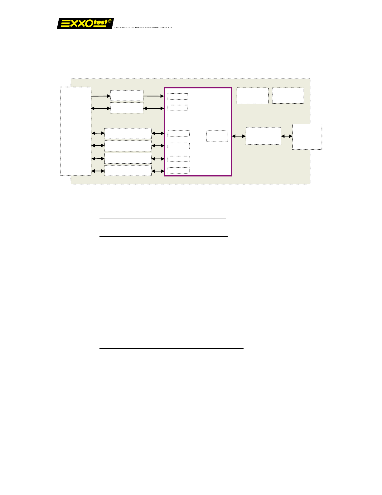
2.1.2. Synoptic
2.1.3. Main characteristics of the CAN channel
2.1.4. Protocol controller: INFINEON TWINCAN
- Standard CAN 2.0B
- Standard identifier 11 bits; extended 29 bits
- Transmission / reception of data up to 8 bytes
- Request for distant transmission (RTR)
- Baud rate up to 1 Mbit/sec
- Spy mode (no acknowledgement or error frame)
- Reading of counters of internal errors
- Detailed information in case of bus error
2.1.5. High speed line interface: PHILIPS PCA82C251
- Standard ISO 11898–24V
- Baud rate up to 1 Mbit/sec
- Channel up to 110 stations on the bus
- Transmission in differential mode
- Short circuit to ground and > 24V battery
UART2
CAN1
Diagnostic
connector
SAE J1962
Regulators
Quartz/
Oscillator
MCU 16 bits XC161CS
USB
connector
INPUT
ISO L
GPIO
UART1
CAN2
K2/LIN2 K4/LIN4
CAN1 HS/LS
CAN2 HS
K1/LIN1 K3/LIN3
USB controller
BUS
ADC
USB-MUXDIAG-II – User guide
16/05/2012 00283735-v1 7
Document confidentiel appartenant à Annecy Electronique S.A.S.
Ne peut être diffusé, copié intégralement ou en partie sans autorisation expresse préalable
2.1.6. Low speed line interface: PHILIPS TJA1054
- Baud rate up to 125 Kbit/sec
- Channel up to 32 stations on the bus
- Transmission in differential mode
- Possibility to operate on 1 wire
- Detection and treatment of degraded modes
o Short-circuit to ground
o Short-circuit to VCC
o Short-circuit to the battery
o Short-circuit between CANH and CANL
o Open circuit
2.1.7. Main characteristics of the LIN/ISO9141 channel
- Standard ISO 9141 or ISO 14230
- Baud rate of 9600, 10400, 62500 and 125000 Bauds
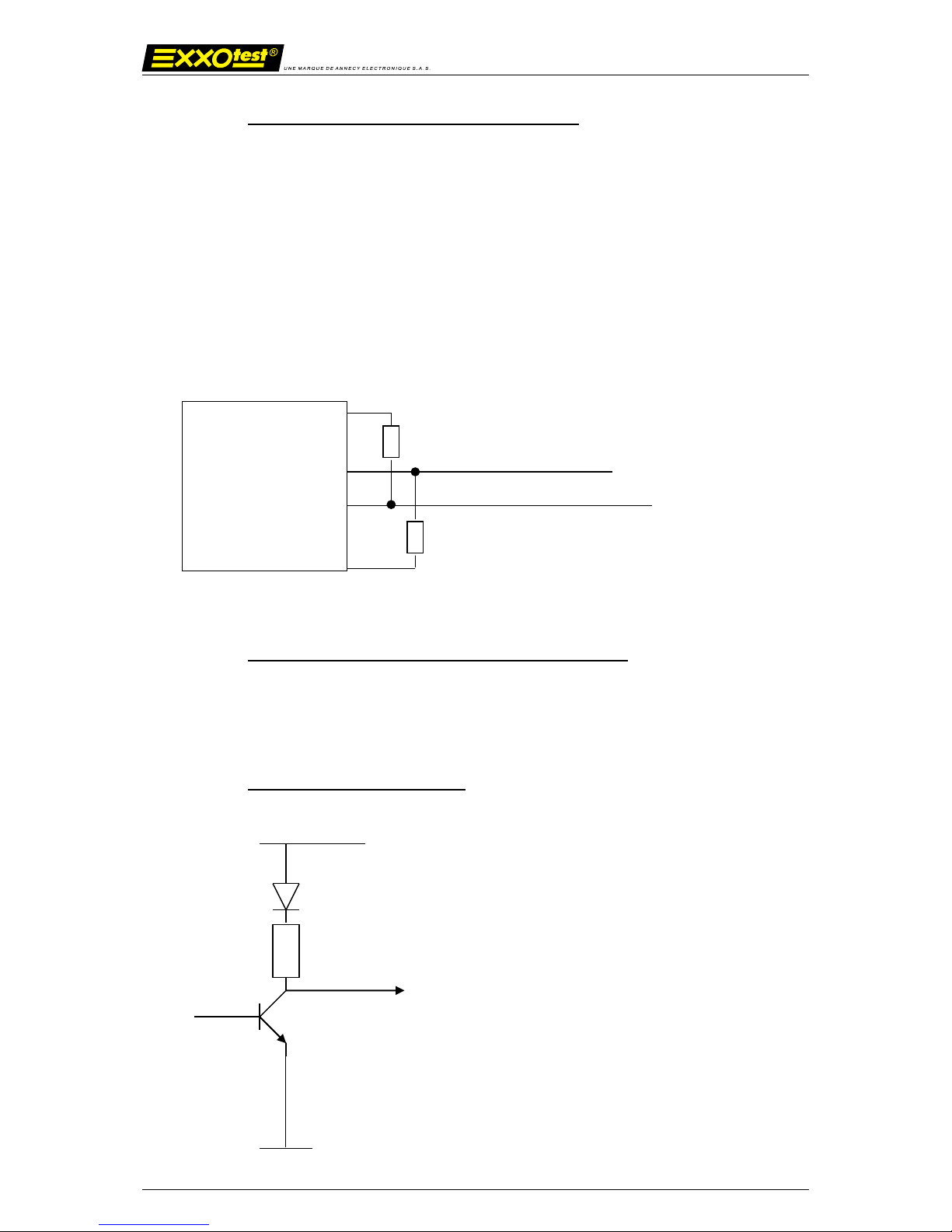
2.1.8. Line interface : tester mode
+VBAT
R1 = 510 Ohm
CAN_H
CAN_L
RTH = 4,7 k
TJA1054
USB-MUXDIAG-II – User guide
16/05/2012 00283735-v1 8
Document confidentiel appartenant à Annecy Electronique S.A.S.
Ne peut être diffusé, copié intégralement ou en partie sans autorisation expresse préalable
2.1.9. Main characteristics of the LIN channel
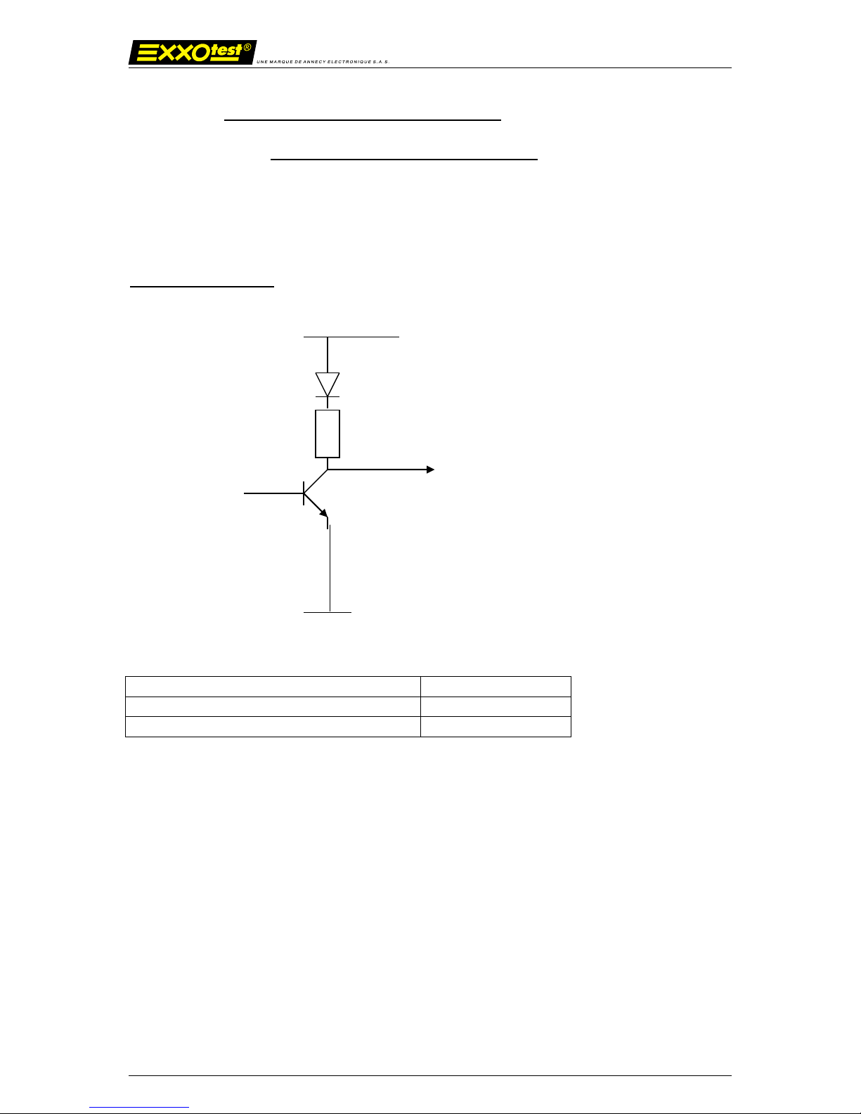
2.1.10. Line interface : MOTOROLA MC33661
- Specification LIN Rev 1.2, 1.3 and 2.0.
- Baud rate of 2400 bauds, 9600, 19200 and 20883 bauds
- Pull-up resistor configuration in master or salve to be chosen through the software
Line emitter / receiver
Configuration
R1
LIN master mode
1 K
LIN slave mode
30 K
+VBAT
R1
USB-MUXDIAG-II – User guide
16/05/2012 00283735-v1 9
Document confidentiel appartenant à Annecy Electronique S.A.S.
Ne peut être diffusé, copié intégralement ou en partie sans autorisation expresse préalable
3. Technical specifications
3.1.1. Characteristics
Presentation
PC interface case for USB bus including :
- 2 CAN channels
- 2 LIN/ISO channels
- 2 ISO/LIN channels
Controller
CAN : 1 Infineon TWINCAN controller
LIN/ISO : 2 UART
Line interface
- CAN high speed : TJA1040
- CAN low speed : TJA1054
- LIN/ISO: MC33661
Digital inputs / outputs
- 1 analog or digital input 0-16V
- 1 analog or digital input power supply supervision
(battery voltage measurement) – detection level 5 Volts
± 5%
Connector
16 pins diagnostic connector (SAE J1962)
PC/POCKET PC interface
USB bus 12 Mbit/sec
Dimensions
140 x 58 x 23 mm
Power supply
Provided by USB bus or vehicle (6-36V)
Consumption
Standby mode< 30 mA (12V)
Active mode < 200 mA (12V)
Storage temperature
-40 to +85°c
Operating temperature
-20 to +70°c
Isolation
Not isolated
3.1.2. ECM Compatibility
- EN 55022 (98) + A1 (00) Mesures des perturbations rayonnées en cage full anéchoide
- EN 55022 (98) + A1 (00) Mesures des perturbations conduites Alimentation AC
- EN 61000-4-2 (95) + A1 (98) + A2 (01) Immunité aux décharges électrostatiques
- EN 61000-4-3 (02) + A1 (02) Immunité aux champs électromagnétiques rayonnés 2
faces
- ISO 7637 (02) Immunité aux perturbations conduites (pulse 1, 2a, 2b, 3a, 3b, 4, 5)
 Loading...