


MULTIFUNCTION DIGITAL CONTROLLER CL550
For automobile diagnostics Oscilloscope, Voltmeter, EOBD reader
USER’S GUIDE
(Original copy)
1
5
6
10
2
7
8
9
11
13
12
14
3 4
(Key on last page)
www.exxotest.com
WARRANTY: 2 years parts and labour
48h-repair on return to factory, shipping paid
by sender
Document N° 00297502-v1
ANNECY ELECTRONIQUE S.A.S.
Parc Altaïs, 1 rue Callisto
74650 CHAVANOD
Tel: +33 (0)4 50 02 34 34
Fax: +33 (0)4 50 68 58 93

WARNINGS AND PRECAUTIONS FOR USE
READ CAREFULLY BEFORE USING THE CL550
To ensure that the CL550 is used safely and to prevent damage to
the device:
Use the CL550 in full respect of the instructions given in this
manual, to avoid damaging its built-in protection.
Do not use the CL550 if the device or its measuring cords are
damaged, or if the device does not seem to be working correctly.
Check that the CL550 is operating correctly by measuring a
known voltage. If there is any doubt - have the equipment
checked.
Never apply a voltage higher than 50V to the measurement
terminals.
Do not use the device in the vicinity of explosive gases, steam or
dust.
Respect all safety instructions concerning the equipment being
tested.
!
2

CONTENTS
1. GENERAL PRESENTATION .................................................................. 4
CONNECTING THE DEVICE ............................................................................................. 4
CONTENTS OF CL550 CASE ........................................................................................... 4
AVAILABLE OPTIONS ....................................................................................................... 5
2. MAIN SCREEN ....................................................................................... 6
CONTROL BUTTONS........................................................................................................ 7
3. DIAGNOSTIC FUNCTION ...................................................................... 7
4. DC VOLTMETER FUNCTION ............................................................... 10
5. DC AMMETER FUNCTION ................................................................... 11
6. OSCILLOSCOPE FUNCTION............................................................... 12
CONFIGURING SETTINGS ............................................................................................. 12
SELECTING MEASUREMENTS, PAUSE FUNCTION, EXAMPLES ............................... 14
......................................................................................................................................... 14
7. SETTINGS MENU ................................................................................. 15
8. USE WITH A COMPUTER .................................................................... 16
INSTALLING THE DRIVER .............................................................................................. 16
INSTALLING THE USB CAPTURE SOFTWARE ............................................................ 17
INSTALLING THE USB UPDATE SOFTWARE ............................................................... 19
9. TECHNICAL SPECIFICATIONS ........................................................... 20
10. CE DECLARATION OF CONFORMITY ................................................ 23
DESCRIPTION ................................................................................................................. 24
3

A
both of the measuring wires provided (item
B).
B
D
provided in the case with the CL550 device.
1. GENERAL PRESENTATION
CONNECTING THE DEVICE
The EXXOTEST® CL550 digital controller can be used
in different ways:
- EOBD reader:
In this case, connect the CL550 to the diagnostic port of
the vehicle inspected. This mode uses the device's
EOBD connection (item A).
- Voltmeter, Oscilloscope:
The voltage readings require the use of one or
- Power supply:
If the EOBD reader is not used, the CL550
can be powered directly by the vehicle
battery, using the adapter provided (item C).
- Dialogue with PC:
C
The USB cable (item D) enabling dialogue with a
computer and the USBCapture software are also
4

CONTENTS OF CL550 CASE
Instructions and CD-Rom (contains
the user manual and software)
Measuring wires with touch
points (1 red, 1 black)
CL550 device with EOBD built-in
lead (vehicle diagnostic port)
EOBD cable / clamps for
direct power supply from
vehicle battery
USB cable: connection of CL550 to
computer (for printing, updates, etc.).
Once connected to the vehicle (diagnostic port or battery), or to the
computer (USB port), the CL550 emits an audible signal and displays the
home screen:
The device is ready for use
AVAILABLE OPTIONS
Optional cord (AMUX-COBD3-L): used
to power the CL550 from the 4 mm
terminals featured on training mock-ups
or stabilised power supply.
Ammeter clamp
(ref.: PA25)
5

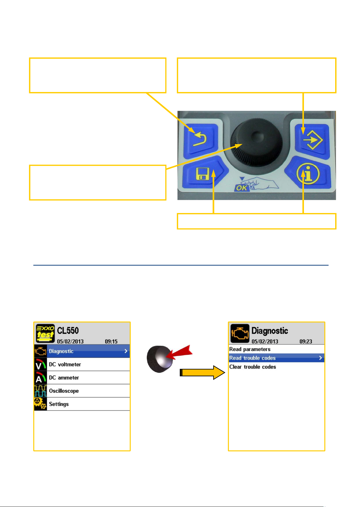
in the example above: Diagnostic is selected.
2. MAIN SCREEN
When the CL550 device is powered up,
it emits an audible signal and the home
screen is displayed. The first line
Diagnostic is selected by default (see
illustration).
10
Use the centre button (item 10) to
browse the device menus.
Select:
Rotate the selector button to move the
cursor.
Confirm:
Press the selector button to access the
mode selected.
The menu selected is highlighted in blue:
6
Press to confirm the selection
or oscilloscope).
Inactive buttons
current mode.
CONTROL BUTTONS
Back:
Closes a menu or quits the
Selector button:
Rotate to change the selection
3. DIAGNOSTIC FUNCTION
Settings:
Shortcut to Settings menus (general
The diagnostic function is selected by default when the device is powered-up.
Press the centre button to enter this mode:
7

in the bottom part of the screen.
listed (
see next page).
If the following screen is displayed, several situations are possible:
Either the EOBD port is not connected, or
The vehicle
(or equipment) connected does not use
the EOBD standard, or
The vehicle
ignition is off.
Once the device is connected, three choices are available:
- Read parameters:
The parameters returned by the vehicle are
displayed; the selected parameter is described
- Read fault codes without the presence of
faults:
If the engine management system queried is
operational, the message 'No fault code' is
displayed. Otherwise, the faults present are
8

codes, confirmation is shown in the illustration.
Read fault codes with presence of faults:
Number of fault code
Description of fault code
Full description of the fault code selected
Fault code level: transient, awaiting confirmation or confirmed.
- Erase fault codes:
Select this line and confirm to erase fault
9

OR
4. DC VOLTMETER FUNCTION
Select the DC Voltmeter mode on the main screen (rotate the centre
button to reach it) and confirm (press the centre button) to be presented
with two possibilities: 1 channel or 2 channels
Use the red wire to measure a single voltage in relation to the battery Earth
(1 channel) or the red and black wires to measure two distinct voltages in
relation to the battery Earth (2 channels).
10

OR
DC Voltmeter, additional information:
In 1 channel mode, the measurement is taken by default in
relation to the battery Earth, but it may pertain to the
difference in potential between the two inputs (red in
relation to black), if the black terminal is connected to
another potential than the battery Earth.
5. DC AMMETER FUNCTION
Select the DC Ammeter mode on the main screen (rotate the centre button
to reach it) and confirm (press the centre button) to be presented with two
calibrations (depending on the ammeter clamp used and the intensity
measured): 1 mV / A or 10 mV / A.
The DC Ammeter mode requires the use of an ammeter clamp that
is not supplied with the CL550 device (see options on page 5).
11

with two traces.
7
2
3
6. OSCILLOSCOPE FUNCTION
Select the Oscilloscope mode on the main screen (rotate the centre
button to reach it) and confirm (press the centre button) to be presented
1
4
5
6
The configuration details are indicated at the top and bottom of the oscilloscope:
1. Trigger mode: Normal or Auto Stop indication when acquisition is paused
2. Position of trace 1 (yellow line, red terminal) / trace 2 (blue line, black
terminal)
3. Calibration of channel 1 (in yellow) and calibration of channel 2 (in blue)
4. Time base (from 100 µs to 10 sec).
5. Indication of current setting: icon same colour as signal concerned
6. Trigger level
7. Trigger channel, type of edge, trigger level (in V), trigger position (in %)
12

CONFIGURING SETTINGS
13
Select
10
11
Confirm
Press button 13 to view the oscilloscope settings menu (press again to close
the menu). Use the centre button 10 to select and confirm a setting. Use
button 11 to return to the previous screen.
- Automatic setting: the CL550 automatically
manages the trace display.
- Timebase: serves to define the time scale for
traces (possible values from 100 µs to 10 sec).
- Active channel: selects the channel on
which you wish to adjust the settings.
- Calibration: defines the calibration assigned
to the active channel (possible values from 500
mV to 10 V).
- Trace position: serves to modify the position
of the active channel trace.
- Trigger channel: selects the trigger channel
(channel 1 or channel 2).
- Trigger level: defines the voltage level at
which measurement will be triggered.
- Trigger position: positions the trigger point on the trigger channel.
- Trigger edge: defines whether measurement is triggered on the rising edge
or falling edge on the trigger channel.
- Trigger type : select the trigger mode: Auto or Normal
- Measurements: selects the measurements to display (see next page).
13
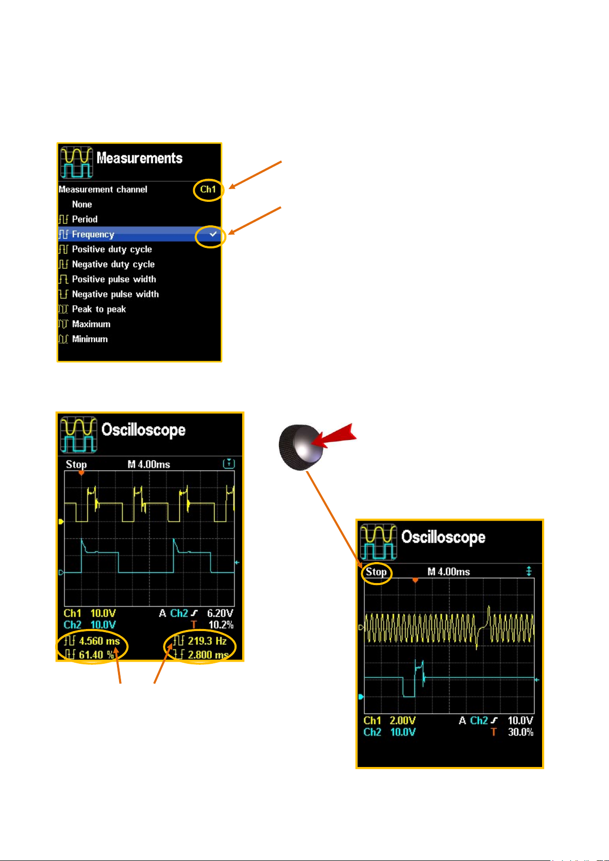
SELECTING MEASUREMENTS, PAUSE FUNCTION, EXAMPLES
Select and confirm the menu choice Measurements in the previous screen
and confirm one of the 4 lines proposed, then you will be able to:
Select the channel for which you
wish to display the measurement,
Select a measurement amongst
those proposed.
Define one measurement then
use the Back button (item 11,
p.13) to define another.
Press the Menu button (item 13,
p.13) to return to the oscilloscope.
The pre-defined measurements
are displayed at the bottom of the
screen.
While taking a
measurement, press the
centre button once to pause
the oscilloscope, press it
again to restart.
14

7. SETTINGS MENU
From the home menu:
Rotate the centre button to move the
cursor and make your selection.
Press the same button to confirm
your settings.
15

8. USE WITH A COMPUTER
INSTALLING THE DRIVER
The CD-Rom provided with the CL550 device contains 3 executable files.
But before connecting the device to a PC using the USB cable supplied, you
need to install the device driver. To do so, double-click the file
'Exxotest_driver_Setup....exe.
The install wizard will start and asks you to select the installation language.
Then validate a succession of screens to reach that shown below:
Once the installation is complete, you may connect the CL550.
16

INSTALLING THE USB CAPTURE SOFTWARE
The CD-Rom supplied with the CL550 device contains the following program
USBCapture_Setup_....exe
Double-click the .exe file and complete the installation steps.
When installation is complete, run the software. When the CL550 is connected
using the USB cable, the following windows appear:
- The magnifying tool to the right of Connected devices, serves to
recognize the device if it was not connected when the software was
opened.
- The serial number of your device appears alongside the product name.
- The parameters in Preview serve to centre and enlarge the preview
window (x2 or x3 zoom).
-
17

Important note: for the oscilloscope windows, you also
need to press one of the CL550 buttons!
- Click this icon to refresh the preview.
- Used to save the screen display as an image.
- Continuously refreshes the screen preview of the
CL550
(in this case, it is not possible to save the image).
- Stop continuous reading.
18

INSTALLING THE USB UPDATE SOFTWARE
The CD-Rom supplied with the CL550 device contains the following program
Setup_USBMaj_DIDAC.exe
Double-click the .exe file and complete the installation steps.
When installation is complete, run the software.
When the CL550 is connected using the USB cable, the following windows
appear:
This program updates
your CL550 device
online.
19

On USB port: +5 V +/
-
0.25 V
9. TECHNICAL SPECIFICATIONS
GENERAL SPECIFICATIONS
Power supply
Display 3.5" colour screen 1/4 VGA 240 320
PC connection High speed USB 2.0 link
On the vehicle diagnostic port or on the
battery: +7V to +36V
Max. admissible voltage on
50 V DC
measurement terminals
Reference temperature 23°C +/-2°C
Operating temperature From -20°C to +70°C
Storage temperature From -30°C to +80°C
BATTERY VOLTAGE MEASUREMENT (CL550 power voltage)
Range
0 to 36 V 0.1 V 0.25V 7,3 kΩ
Reading
resolution
Accurate from
Impedance
-20°C to +70°C
20

VOLTAGE MEASUREMENT
with black and red terminals (item .4. on cover page),
in relation to power supply Earth
Range
Reading
Accurate from
Impedance
(full scale)
resolution
-20 to 70°C
-15 V to +15 V 0.01 V +/-0.25 V 2 MΩ
-50 V to +50 V 0.01 V +/-0.25 V 2 MΩ
VOLTAGE MEASUREMENT
red terminal in relation to black terminal
(item .4. on cover page)
Range
Reading
Accurate from
Accurate from
Impedance
(full scale)
resolution
18 to 28°C
-20 to 70°C
-15 V to +15 V 0.01 V +/-3 mV +/-15 mV 2 MΩ
-50 V to +50 V 0.01 V +/-50 mV +/-150 mV 2 MΩ
with DC/DC clamp on black and red terminals
Range
(full scale)
Reading
resolution
+/-2 V 1 mV +/-0.25 mV +/-1.5 mV 2 MΩ
DUAL-TRACE OSCILLOSCOPE MEASUREMENT
Scale Time base
0.5 / 1 / 2 / 5 / 10
from 100 µs to 10
Volt / division
AMMETER
(item .4. on cover page)
Accurate from
18 to 28°C
Accurate from
-20 to 70°C
with black and red terminals
(item .4. on cover page)
Sampling
frequency
500,000
sec
samples/sec
Impedance
Bandwidth
50 kHz
21

ISO15765
-
2 (DiagOnCan)
Physical connections
Communication protocols
and OBD modes
Known fault codes SAE J2012 / ISO 15031-6
EOBD READING II
ISO 9141-1 (ISO)
ISO14230-1(KWP2000)
ISO15765-2 (DiagOnCan)
SAE J1979 (April 2002)/ISO 15031-5 (April
2002)
ISO 9141-2 (ISO)
ISO14230-1(KWP2000)
OBC connector SAE J1962 / ISO 15031-3
PC function Update via USB
Measurement units Metric
10.4 kbit/s on ISO links and KWP2000
Communication speed
250 kbit/s or 500 kbit/s on the CAN link
22

10. CE DECLARATION OF CONFORMITY
ANNECY ELECTRONIQUE S.A.S
Parc Altaïs – 1, rue Callisto
74650 CHAVANOD – FRANCE
Declares that the following product:
Brand Model Description
EXXOTEST® CL550 Multifunction digital controller
I. Has been manufactured in accordance with the requirements of
EMC Directive 2004/108/EC - 15/12/2004
and satisfies the requirements of the following standard:
NF EN 61326-1 dated 07/1997 +A1 of 10/1998 +A2 of 09/2001, Electrical
measurement, control and laboratory equipment, EMC-related requirements.
II. Has been manufactured in accordance with the requirements of the European
Directives relating to EEE design and WEEE management for the EU :
Directive 2002/96/EC dated 27 January 2003 on Waste Electronic and Electrical
Equipment (WEEE)
Directive 2002/95/EC dated 27 January 2003 on the limitations for the use of certain
hazardous substances in the construction of Electronic and Electrical Equipment
(EEE).
III. Person authorised to present technical files in the EU:
SORLIN Stéphane, Parc Altaïs, 1 rue Callisto 74650 Chavanod.
Drawn up in Chavanod on 01 October 2012,
CEO - Stéphane SORLIN
23

ITEM
1
2
3
CONNECTIONS
4
5
6
7
MAIN MENU
8
DESCRIPTION
EOBD 16-channel connector for communication with the
vehicle and/or device power supply
USB port for communication with a PC
Specific connector for future options
Connection terminals for measurement cables 1 and 2 or the
ammeter clamp
Diagnostic mode: ODB Reader function
Voltmeter mode: Voltage measurements
(channel 1, channel 2 and Battery voltage)
Ammeter mode: intensity measurements using an ammeter
clamp (1 mV/A or 10 mV/A)
Dual-trace Oscilloscope mode
9
10
11
12
13
CONTROL BUTTONS
14
www.exxotest.com
WARRANTY: 2 years parts and labour
48h-repair on return to factory, shipping paid
Document N° 00286130-v1
by sender
Settings menu on CL550
Rotate the centre button to browse the choices on the screen
and press to confirm.
The Back button serves to close a menu or a window, or to
quit the current mode.
Save button: currently inactive
The Menu button serves to display the oscilloscope settings.
Print button: currently inactive.
Description of device presented on cover page.
ANNECY ELECTRONIQUE S.A.S.
Parc Altaïs, 1 rue Callisto
74650 CHAVANOD
Tel: +33 (0)4 50 02 34 34
Fax: +33 (0)4 50 68 58 93
 Loading...