

Page 1
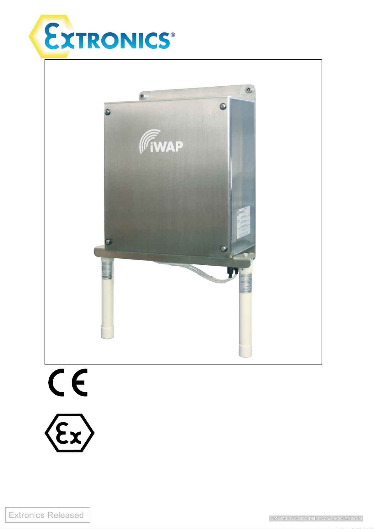
Installation & Operating Manual
iWAP200
Page 2

Operating Manual
2
Document Number 401983 (See Last Page for Revision Details)
©2019 Extronics Limited. This document is Copyright Extronics limited.
Extronics reserve the right to change this manual and its contents without notice, the latest
version applies.
Warranty
For full details of the Extronics warranty policy please go to the Company section of the
Extronics website and download Terms and Conditions.
Page 3

Operating Manual
3
Contents
1 Introduction .......................................................................................................... 4
2 Safety Information and Notes .............................................................................. 5
2.1 Storage of this Manual ................................................................................... 5
2.2 ATEX Special Conditions of Safe Use ........................................................... 5
2.3 List of Notes .................................................................................................. 5
3 Installation and Setting-to-Work .......................................................................... 8
3.1 Installation ..................................................................................................... 8
3.1.1 Removing the cover ................................................................................ 8
3.1.2 Fitting the cables ..................................................................................... 9
3.1.3 Mains & PoE Variant Cable Installation .................................................. 9
3.1.4 Fibre Ethernet Input .............................................................................. 11
3.1.5 24VDC Variant Cable Installation .......................................................... 11
3.1.6 Fibre Ethernet Input .............................................................................. 13
3.1.7 Thermostat Control ............................................................................... 13
3.1.8 Fitting the antennas .............................................................................. 13
3.1.9 Mounting The Antennas ........................................................................ 14
3.1.10 Setting to work ................................................................................... 15
4 Intended Purpose Usage ................................................................................... 16
4.1 Transportation and Storage ......................................................................... 16
4.2 Authorized Persons ..................................................................................... 16
4.3 Cleaning and Maintenance .......................................................................... 16
4.3.1 Screw Thread Lubrication ..................................................................... 16
4.3.2 Surface Coating .................................................................................... 17
4.4 Safety Precautions ...................................................................................... 17
4.5 Cleaning and Maintenance Intervals ........................................................... 17
4.6 Aggressive substances and environments .................................................. 17
4.7 Exposure to external stresses ..................................................................... 17
5 Technical Data .................................................................................................. 18
6 Enclosure Dimensions ....................................................................................... 19
7 Label Drawing ................................................................................................... 20
8 Type Codes ....................................................................................................... 21
9 EC Declaration of Conformity ............................................................................ 22
10 Manual Revision ................................................ Error! Bookmark not defined.
Page 4

Operating Manual
4
1 Introduction
The iWAP200 Zone 2 Access Point Enclosure is designed to deploy wireless
networks in hazardous areas. The concept allows installation o f equipment from
leading WLAN vendors such as Cisco, Meru, Symbol and Firetide.
Each type of Access Point or RF transmitting device is rigorously checked and
tested by Extronics and our Notified Body to ensure conformity to the ATEX
standards and approvals. This means that Extronics can provide an OEM a
solution to enable your WLAN network devices to be installed in hazardous
areas.
The Extronics iWAP200 is designed for use with one to four standard antennas or
Extronics iANT200 series of intrinsically safe antennas for optimum coverage on
Chemical Plants, Oil Refineries or Oil & Gas Platforms.
Optional features include surge arrestors for lightening suppression in outdoor
installations and either single and multimode fibre inputs for the Ethernet,
enclosure heating or cooling for low/high temperatures and anti-condensation
plus the option of plug and socket cable entry instead of cable glands.
Page 5
Operating Manual
5
2 Safety Information and Notes
2.1 Storage of this Manual
Keep this user manual safe and in the vicinity of the device. All persons who have to work on
or with the device should be advised on where the manual is stored.
2.2 ATEX Special Conditions of Safe Use
No special conditions of safe use are listed in the ATEX certificate
List of Notes
The notes supplied in this chapter provide information on the following.
• Danger / Warning.
o Possible hazard to life or health.
• Caution
o Possible damage to property.
• Important
o Possible damage to enclosure, device or associated equipment.
• Information
o Notes on the optimum use of the device
Warning Installation to be by skilled electricians and instructed personnel in
accordance with national legislation, including the relevant standards
and, where applicable, in accordance with IEC 79.17 on electrical
apparatus for explosive atmospheres.
Warning For the installation, maintenance and cleaning of the units, it is
absolutely necessary to observe the applicable regulations and
provisions concerned with explosion protection (EN60079-0, EN 60079-
14) as well as the Accident Prevention Regulations.
Warning The iWAP200 must NOT be operated in ATEX Zone 0/20 or Zone 1/21
hazardous areas. Refer to the declaration of conformity for ATEX
certificate information.
Warning Do not exceed the Effective Isotropic Radiated Power (EIRP) for the gas
group in which the iWAP200 will be operating. The RF output of the
transceiver will vary depending on the hardware and antenna used. The
maximum hardware limit of the access point must be used to calculate
the EIRP – software control by the user of the RF power is not allowed
IIC – 2W (+33dBm)
IIB – 3.5W (+35.4dBm)
IIA – 6W (+37.7dBm)
Warning The iWAP200 MUST be earthed.
Page 6

Operating Manual
6
Warning If cable glands different to those supplied by Extronics are used, these
must be M20 sized cable glands meeting the requirements of
EN60079-0:2009 for ATEX Category III GD equipment, and not
compromise the IP66 rating of the iWAP200 enclosure.
Warning The technical data indicated on the iWAP200 rating plate, this manual
and the ATEX certificate must be observed.
Warning Changes in the design and modifications to the equipment are not
permitted. This includes adding or removing heaters/fans which were
installed by Extronics Ltd. Changing the pre-installed Access points
and/or MESH routers is NOT permitted.
Warning The iWAP200 shall be operated as intended and only in an undamaged
condition.
Warning Only antennas which have been approved for use by Extronics for the
area which they are to be installed may be used with iWAP200.
Caution This assembly may weigh up to 10Kg depending on requirements,
therefore ensure the assembly is mounted using suitable fixtures.
Caution When powering the iWAP200 via POE do not apply an external power
supply to the protection board.
Caution Never power the iWAP200 via POE if fans and/ or heaters are installed.
Important Antenna connections must be sealed once installed to prevent the
ingress of moisture. Standard RF connector sealing using selfamalgamating tape should be used.
Important The iWAP200 must not be stored or operated outside of its rated
temperature range as stated on the ATEX certificate.
Important The nylon washers on the underside of the enclosure lid must be used
with the gasket to maintain the IP rating of the enclosure.
Important To maintain the IP rating of the enclosure, the lid screws must not be
removed or replaced with different screws.
Important Ensure that the lid gasket is clean and undamaged before fitting the lid.
Take care not to trap the lid earth cable in the gasket when closing the
lid.
Important The iWAP200 is supplied fitted with anti-seize grease on the lid screws.
Ensure that this is not removed during installation. See section 4.3.1 for
maintenance details.
Page 7

Operating Manual
7
Important The iWAP200 is supplied with a protective coating to prevent ‘tea
staining’ of the stainless steel enclosure. Take care to avoid damage to
this coating during handling and installation. Do not use abrasive
substances to clean the enclosure. See section 4.3.2 for maintenance
details.
Information Do not exceed the Effective Isotropic Radiated Power (EIRP) limit for
the country/region of operation
Information For legacy reasons, the RF outputs of the iWAP200 remain approved in
accordance with EN60079-15:2005 as Ex nL (energy limited), and the
iWAP200 remains solely marked as such.
However, the iWAP200 RF outputs are also compliant with the
requirements of EN60079-11:2012, therefore the iWAP200 is also
approved as:
A II 3 G Ex nA [ic]
Uo=negligible, Io=negligible, Po=0.5W, Co=negligible, Lo=negligible
Page 8
Operating Manual
8
3 Installation and Setting-to-Work
3.1 Installation
The iWAP200 is simple to install and can be secured directly to suitable surface
using the mounting holes on the Enclosure.
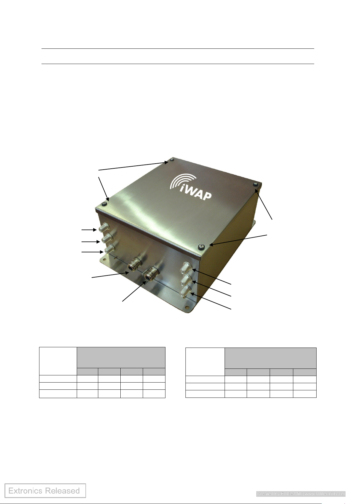
3.1.1 Removing the cover
Unscrew the four screws and remove the enclosure lid.
See table below for antenna connections:
Antenna
Connection
Number of N-type connectors
ordered for Radio 1
(2.4GHz Default)
0 1 2 3 R1-A
x
✓ ✓ ✓
R1-B
x
x
✓
✓
R1-C
x x x
✓
Note: For Radio 1 (R1) and Radio 2 (R2) on any manufacturers Wireless Access
point, A will be antenna port 1, B will be antenna port 2, and C will be antenna port 3.
For example:
If you have ordered 1 N-type connector for Radio 1, and 2 N-type connectors for
Radio 2. Then R1-A will be connected to antenna port 1 of Radio 1, R2-A will be
connected to antenna port 1 of Radio 2, and R2-B will be connected to antenna port
2 of Radio 2 for any manufacturers wireless access point.
Antenna
Connection
Number of N-type connectors
ordered for Radio 2
(5GHz Default)
0 1 2 3 R2-A
x
✓ ✓ ✓
R2-B
x
x
✓
✓
R2-C
x x x
✓
Lid
screws
Lid
screws
Ethernet /Fibre
Cable Entry
AC/DC Power
Cable Entry
R1-C
R1-B
R1-A
R2-C
R2-B
R2-A
Page 9

Operating Manual
9
3.1.2 Fitting the cables
Depending on the configuration of the iWAP200, the connections for power and
communication will need to be terminated into the enclosure via the correct cable
entries shown in Diagram 3.1.1.
The cables used to connect the power and/or Ethernet connection to the PCB screw
terminals must conform to the following specification;
All wires should be stripped and, if stranded cable is used, should be crimped using
2.5mm bootlace ferrules. The stripped/crimped wires should then be placed into the
corresponding screw terminal and securely screwed in place.
If using solid core cable;
Minimum cross section of cable = 0.2mm
2
Maximum cross section of cable = 2.5mm
2
Maximum cross section of cable for 24VDC connector ONLY = 6mm
2
If using crimped stranded core cable;
Minimum cross section of cable = 0.25mm
2
Maximum cross section of cable = 1.5mm
2
Maximum cross section of cable for 24VDC connector ONLY = 4mm
2
Warning The iWAP200 MUST be earthed.
Important All cables should be connected to the iWAP200 via the correct cable
gland, fitted by a competent person.
Important If cable glands different to those supplied by Extronics are used, these
must be M20 sized cable glands meeting the requirements of
EN60079-0:2009 for ATEX Category III GD equipment, and not
compromise the IP66 rating of the iWAP200 enclosure.
Important Changes in the design and modifications to the equipment are not
permitted. This includes adding heaters/fans which are not installed at
the factory.
Important The installer MUST ensure that that all cables have adequate mechanical
protection to avoid damage to the wires.
3.1.3 Mains & PoE Variant Cable Installation
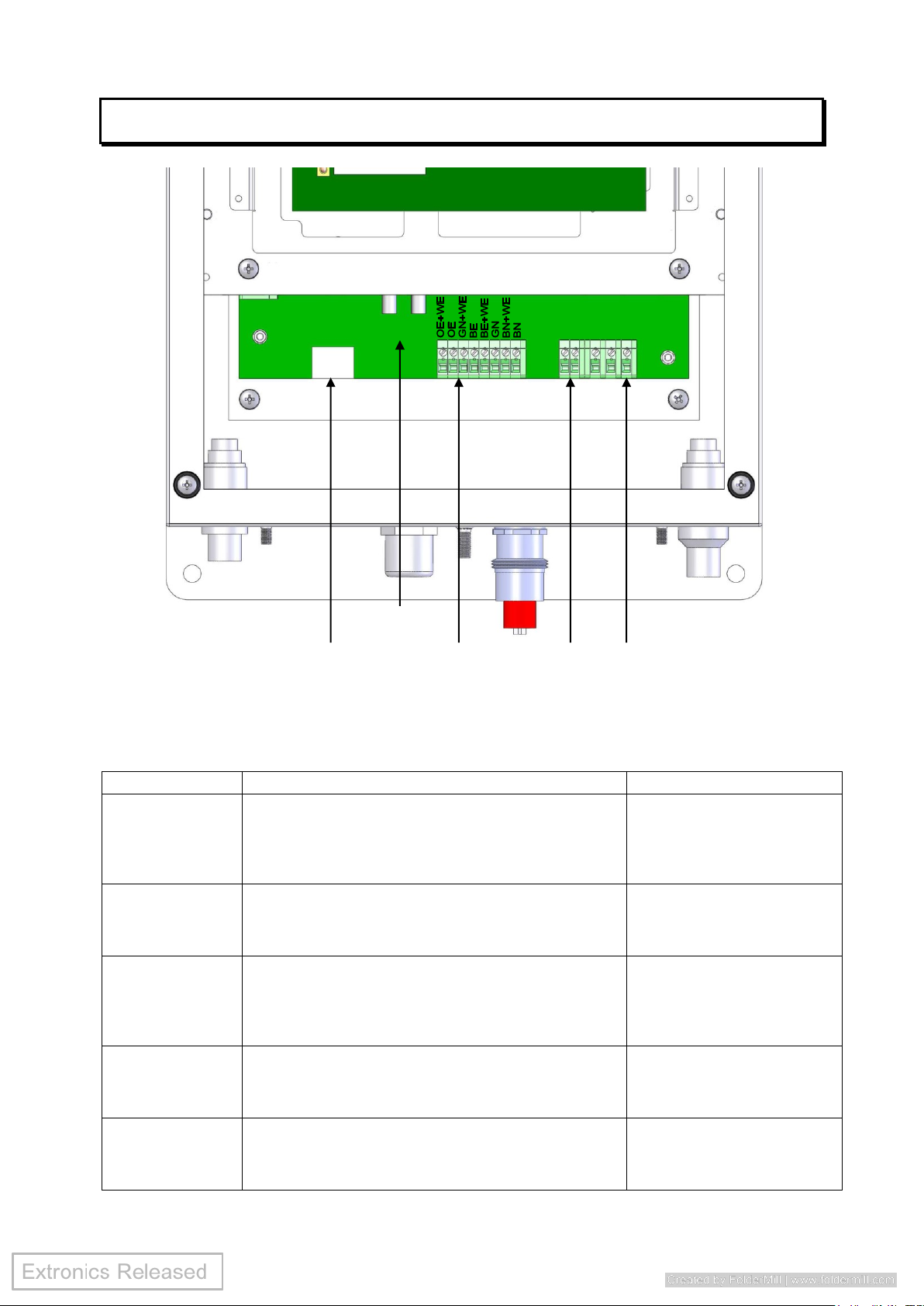
Diagram 3.1.3.1 shows the connectors on the mains and PoE variant of the iWAP200. Table
3.1.3.2 describes the pin out connection required for operation. There are two blocks of
screw terminals and one RJ45 connector. The Ethernet input screw terminals are wired in
parallel with the RJ45 connector. Do not make an Ethernet connection to the RJ45 connector
and the screw terminals at the same time, the installer should use only one of these
connectors.
Follow the instructions in section 3.1.2 to correctly prepare the cables and feed them through
the correct cable gland. Follow table 3.1.3.2 to connect the correct cable to the correct screw
terminal. If using the RJ45 connector instead of the screw terminals simply connect the Cat-5
cable to the connector and ensure the cable is securely in place.
Page 10
Operating Manual
10
Caution Only ever make one Ethernet cable to either the RJ45 connector or
Ethernet screw terminals – NEVER both.
Diagram 3.1.3.1 – Mains Variant & PoE iWAP200 PCB
Connector
Description
Notes
110/230VAC
input
These screw terminals allow the connection of a
110/230VAC power supply. Pinouts are; 1 = Live, 2 =
Neutral, 3 = Earth. If AC powered, no PoE is
required.
Do not apply AC voltage if
powering with PoE
Chassis Earth
There are two terminals which allow a connection to
earth. When the iWAP200 is delivered one of these
terminals will be connected to the enclosure. The
second earth terminal spare.
Ethernet & PoE
Input (Terminals)
Connect a Cat-5 cable to these screw terminals for
the connection of the Ethernet input. The pinouts on
this terminal correspond with the standard cat-5
TIA/EIA-568-B T568B wiring methods.
Only one Ethernet input
should be made, only use
either the terminals or RJ45
connector NOT both.
Ethernet & PoE
Input (RJ45)
This allows the connection of a standard Cat-5 cable
with plugs.
Only one Ethernet input
should be made, only use
either the terminals or RJ45
connector NOT both.
Fibre Input
Allows a fibre connection to be made to the iWAP200
board. The connector will be a ST connector for
multimode fibre input, or a SC connector for single
mode fibre
The copper Ethernet input is
disabled if the fibre module
is fitted
Table 3.1.3.2 – iWAP200 Mains / PoE Variant Pinouts
Ethernet & PoE
Input (RJ45)
Ethernet & PoE
Input
(Screw Terminals)
Chassis
Earth
110/230VAC
Input
L N E
Fibre input
Tx Rx
Page 11

Operating Manual
11
Important Only connectors 110/230VAC Input, Chassis Earth and Ethernet Input
(Terminals or RJ45) are user serviceable. The end user should not
connect, disconnect or alter the wiring on any other connector!
Caution When powering the iWAP200 via POE do not apply an external power
supply to the protection board.
Caution Never power the iWAP200 via POE if fans and/ or heaters are installed.
3.1.4 Fibre Ethernet Input
Important When connecting the access point via a fibre connection do not use
any of the two Ethernet inputs of connectors.
To obtain greater wired link distances the iWAP200 can be shipped with an optional
fibre module. The fibre module will be connected directly to the access point, the user
should attach the fibre cable directly to the fibre module. The fibre cable should be
fed through the Ethernet cable gland.
If a multimode fibre option has been specified the connection is mage via a “ST”
connector.
If a single mode fibre option has been specified, the connection is made via a “SC”
connector.
Important The fibre cable must enter the iWAP200 enclosure via a cable gland, it
therefore may be necessary to terminate the Fibre cable, with the correct
connector, from within the enclosure after the cable has been fed
through the cable gland.
3.1.5 24VDC Variant Cable Installation
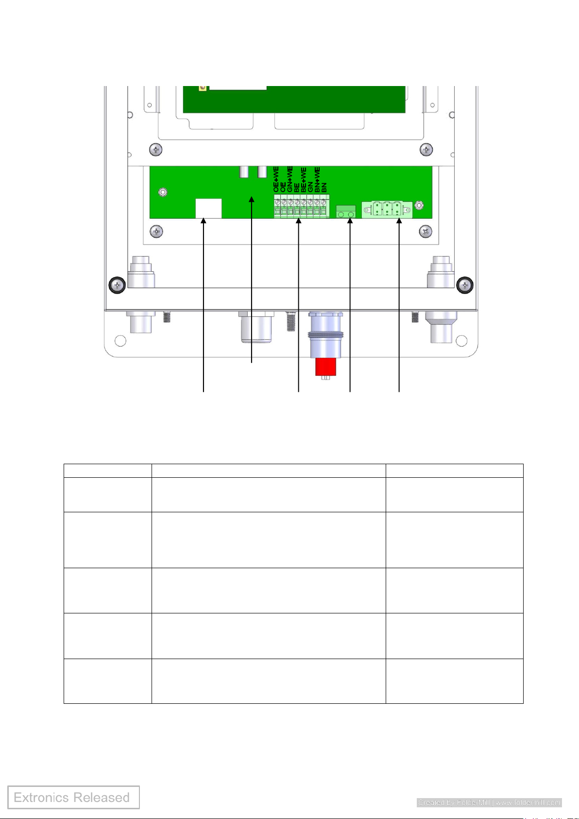
Diagram 3.1.5.1 shows the connectors on the 24VDC variant of the iWAP200. Table
3.1.5.2 describes the pin out connection required for operation. There are two blocks
of screw terminals and one RJ45 connector. The Ethernet input screw terminals are
wired in parallel with the RJ45 connector. Do not make an Ethernet connection to the
RJ45 connector and the screw terminals at the same time, the installer should use
only one of these connectors.
Follow the instructions in section 3.1.2 to correctly prepare the cables and feed them
through the correct cable gland. Follow table 3.1.5.2 to connect the correct cable to
the correct screw terminal. If using the RJ45 connector instead of the screw terminals
simply connect the Cat-5 cable to the connector and ensure the cable is securely in
place.
Caution Only ever connect one Ethernet cable to either the RJ45 connector or
Ethernet screw terminals.
Page 12
Operating Manual
12
Diagram 3.1.5.1 – 24V Variant iWAP200 PCB
Connector
Description
Notes
24VDC input
These screw terminals allow the connection of a
24VDC power supply. Pinouts are; 1 = +24V, 2 =
0V/GND, 3 = Earth/cable outer sheath.
Chassis Earth
There are two terminals which allow a connection to
earth. When the iWAP200 is delivered from
Extronics’ factory one of these terminals will be
connected to the enclosure. The second earth
terminal spare.
Ethernet Input
(Terminals)
Connect a Cat-5 cable to these screw terminals for
the connection of the Ethernet input. The pinouts on
this terminal correspond with the standard Cat-5
TIA/EIA-568-B T568B wiring methods.
Only one Ethernet input
should be made, only use
either the terminals or RJ45
connector NOT both.
Ethernet Input
(RJ45)
This allows the connection of a standard Cat-5
cable with plugs.
Only one Ethernet input
should be made, only use
either the terminals or RJ45
connector NOT both.
Fibre Input
Allows a fibre connection to be made to the
iWAP200 board. The connector will be a ST
connector for multimode fibre input, or a SC
connector for single mode fibre
The copper Ethernet input is
disabled if the fibre module is
fitted
Table 3.1.5.2 – iWAP200 24VDC Variant Pinouts
Ethernet Input
(RJ45)
Ethernet Input
(Screw Terminals)
Chassis
Earth
24 VDC Input
+ 0 E
Fibre input
Tx Rx
Page 13

Operating Manual
13
3.1.6 Fibre Ethernet Input
Important When connecting the access point via a fibre connection do not use
any of the two Ethernet inputs of connectors.
To obtain greater wired link distances the iWAP200 can be shipped with an optional
fibre module. The fibre module will be connected directly to the access point, the user
should attach the fibre cable directly to the fibre module. The fibre cable should be
fed through the Ethernet cable gland.
If a multimode fibre option has been specified the connection is mage via a “ST”
connector.
If a single mode fibre option has been specified, the connection is made via a “SC”
connector.
Important The fibre cable must enter the iWAP200 enclosure via a cable gland, it
therefore may be necessary to terminate the Fibre cable, with the correct
connector, from within the enclosure after the cable has been fed
through the cable gland.
3.1.7 Thermostat Control
The thermostats are currently not user configurable. The default configuration is for
the heaters to be turned on when the internal ambient temperature is between -20oC
and +30oC and for the fans/wireless hardware to be on above -20oC.
3.1.8 Fitting the antennas
• Connect the antennas to the correct the N type connector on the outside of the
enclosure (see Diagram 3.1.1). Make sure to only connect antennas which are
intended to be used at the frequency required (i.e. either 2.4GHz or 5.8GHz
antennas).
• Depending on the options ordered some of the N-types may have been
replaced with blanking plugs or surge arrestors.
• If the version ordered contains both a mesh router and access point; the mesh
router and access point should be setup in software to run at 5.8GHz and
2.4GHz respectively. The iWAP200 will be wired in this way when delivered.
• The iWAP200 may be used with any antenna (all antennas will however, need
to be assessed to the BS EN 60079-11:2007 standard and approved by
Extronics for use with the iWAP200). It is recommended to use the Extronics
iANT200 series of antennas as these have already been pre-approved for use
with the iWAP200.
Page 14
Operating Manual
14
Important Antennas connections must sealed once installed to prevent the ingress
of moisture. Standard RF connector sealing using self amalgamating
tape should be used
Warning Do not exceed the Effective Isotropic Radiated Power (EIRP) for the gas
group in which the iWAP200 will be operating. The RF output of the
transceiver will vary depending on the hardware and antenna used. The
maximum hardware limit of the access point must be used to calculate
the EIRP – software control by the user of the RF power is not allowed
IIC – 2W (+33dBm)
IIB – 3.5W (+35.4dBm)
IIA – 6W (+37.7dBm)
Important Only antennas which have been approved for use by Extronics for the
area which they are to be installed may be used with iWAP200.
Important Any plastic coated antenna shall have a warning label fitted to it stating
“WARNING – Potential electrostatic charging hazard. Wipe only with a
damp cloth”
Information Do not exceed the Effective Isotropic Radiated Power (EIRP) limit for
the country/region of operation
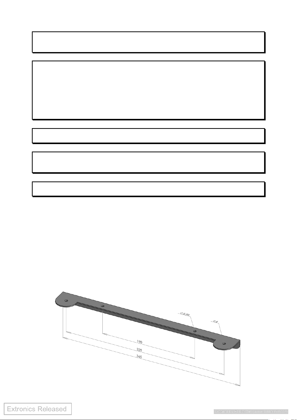
3.1.9 Mounting The Antennas
Extronics can supply two sizes of antenna brackets which can be mounted either on
the top or bottom of the enclosure. The bracket sizes offered are 365mm and 680mm
in length. The brackets allow the mounting of two antennas (either the iANT100 or
iANT200) at the far extremities of the bracket.
3.1.9.1 iANTMB02
316L SS Antenna bracket 365mm length for 2 iANT100 / iANT200
antennas for mounting on an iWAP enclosure
Page 15
Operating Manual
15
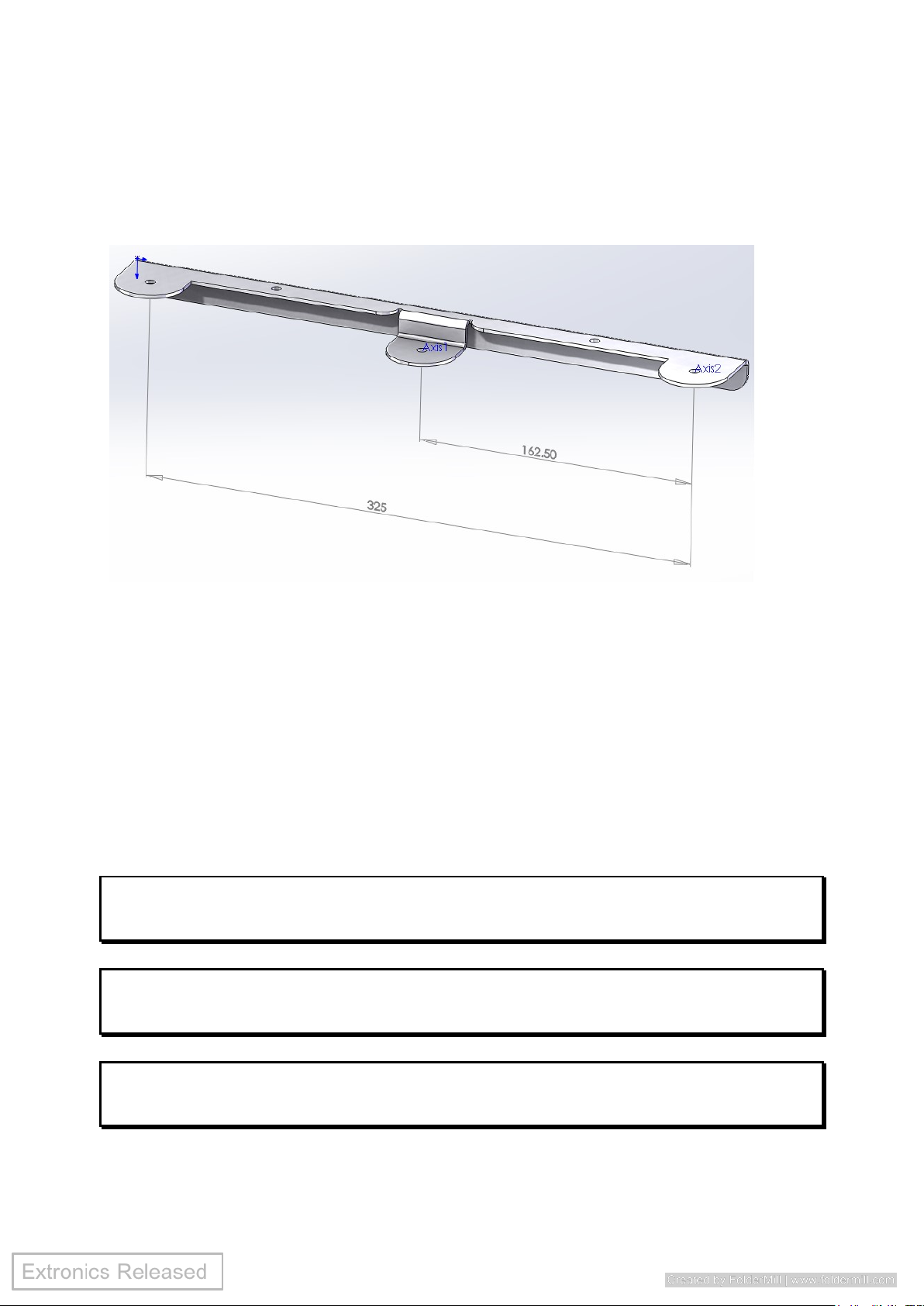
3.1.9.2 iANTMB05
316L SS Antenna bracket 365mm length for 3 iANT100 / iANT200
antennas for mounting on an iWAP enclosure
Bespoke mounting brackets can also be designed for most applications. Please
contact Extronics for more information.
3.1.10 Setting to work
• Once all cables are connected correctly, refit the enclosure lid using the four
screws previously removed. Use a torque screwdriver set to 2.5 Nm. Do not
over tighten screws.
• Refer to the original manufacturers instructions for a detailed information on
setting the network to work correctly.
Important Ensure the lid is secure, correct cable glands are fitted and the unit
device correctly wired and earthed for the particular application before
applying power.
Important The iWAP200 is supplied fitted with anti-seize grease on the lid screws.
Ensure that this is not removed during installation. See section 4.3.1 for
maintenance details.
Important Ensure that the lid gasket is clean and undamaged before fitting the lid.
Take care not to trap the lid earth cable in the gasket when closing the
lid.
Page 16

Operating Manual
16
4 Intended Purpose Usage
Important Before setting the units to work read the technical documentation
carefully.
Important The latest version of the technical documentation or the corresponding
technical supplements is valid in each case.
The iWAP200 is built using modern components and is extremely reliable in
operation; however it must only be used for its intended purpose. Please note that
the intended purpose also includes compliance with the instructions issued by the
manufacturer for installation, setting up and service.
Any other use is regarded as conflicting with the intended purpose. The manufacturer
is not liable for any subsequent damage resulting from such inadmissible use. The
user bears the sole risk in such cases.
4.1 Transportation and Storage
All iWAP200 devices must be so transported and stored that they are not subjected
to any excessive mechanical stresses.
4.2 Authorized Persons
Only persons trained for the purpose are authorized to handle the iWAP200; they
must be familiar with the unit and must be aware of the regulation and provisions
required for correct installation as well as the relevant accident prevention
regulations.
4.3 Cleaning and Maintenance
The iWAP200 and all its components require no maintenance and are selfmonitoring. All work on the iWAP200 by personnel who are not expressly qualified for
such activities will cause the guarantee to become void.
4.3.1 Screw Thread Lubrication
The threads of the lid screws and inserts have been coated with a thin layer of Rocol
251 stainless steel anti-seize grease. It is recommended that this grease should be
periodically renewed if the lid is opened frequently, to prevent the stainless threads
from binding.
Warning Use only Rocol 251 or Loctite 771 as thread lubricants, as other
materials may damage the gasket and invalidate the IP rating of the
enclosure
Page 17

Operating Manual
17
4.3.2 Surface Coating
The iWAP200 enclosure has been coated with a material to prevent ‘tea staining’ of
the stainless steel by build-up of salt deposits in marine environments. Avoid damage
of the surface of the enclosure during handling.
However, if ‘tea staining’ does occur, it is purely cosmetic and does not affect the
performance of the enclosure.
If the coating is damaged, it can easily be re-applied in the field. Contact Extronics for
details.
4.4 Safety Precautions
Important For the installation, maintenance and cleaning of the units, it is
absolutely necessary to observe the applicable regulations and
provisions concerned with explosion protection (EN 60079-0, EN 60079-
14) as well as the Accident Prevention Regulations.
4.5 Cleaning and Maintenance Intervals
The cleaning intervals depend on the environment where the system is installed.
4.6 Aggressive substances and environments
The iWAP200 is not designed to come into contact with aggressive substances or
environments, please be aware that additional protection may be required.
4.7 Exposure to external stresses
The iWAP200 is not designed to be subjected to excessive stresses e.g. vibration,
heat, impact. Additional protection is required to protect against these external
stresses.
The iWAP200 will require additional protection if it is installed in a location where it
may be subjected to damage.
Page 18

Operating Manual
18
5 Technical Data
Power Supply
Universal 90-264VAC, 20-28VDC or IEEE802.3af POE
Maximum Power Consumption
Without heating or cooling POE 802.3af or 16W for mains or DC power
With cooling 21W
With heating and cooling 121W
Enclosure Material
316L Stainless Steel
Ingress Protection
IP66
Weight
Approximately 10 Kg
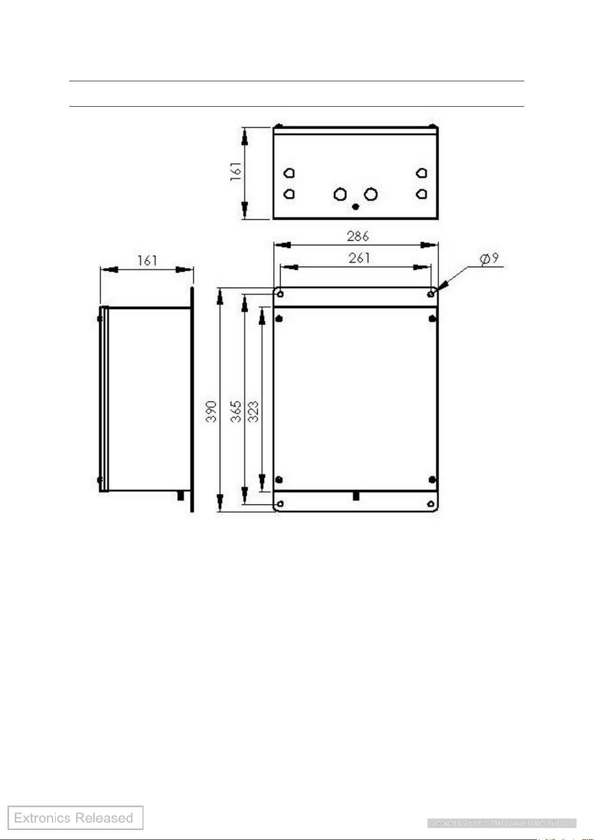
Dimensions
390 x 286 x 161 mm (h x w x d)
Environmental
Typical Operating Temperature (actual temperature range dependant upon access point
used):
Without heating or cooling –20oC to 500C
With cooling –20oC to 600C
With heating and cooling –40oC to 600C
Storage temperature; –40oC to 700C
Relative humidity; 0 to 95%, non condensing
Note: If fibre option chosen the minimum ambient temperature is 0oC. If a lower ambient
temperature is required heaters MUST be fitted
Input Connections
115V/230VAC input option on screw terminals
24VDC input option on screw terminals
10/100BaseT Ethernet on RJ45 socket and screw terminals
10/100BaseFX Multimode fibre input option on ST connectors
100BaseLX-10 Single mode fibre on SC connectors
Note that connectors may be specified as an option in the ordering data
Output Connections
Up to 6 energy-limited external RF outputs via external N-type RF connectors. Surge
arrestors are optional. Customer is to specify the number of required RF outputs
Ethernet Link distance
10/100Base T Ethernet on Cat5e: up to 0.1km
10/100BaseFX on Multimode Fibre: Up to 2km
100Base-LX10 on Single mode fibre: up to 10km
Maximum Internal RF Cable Loss
(between output of access point and
external N-type connector)
2.4GHz 5.0Ghz 5.8GHz
External N-type output 1.40dB 1.90dB 2.10dB
With Surge Arrestor 1.55dB 2.05dB 2.35dB
Radio
Dependant upon chosen hardware
Antennas
To be used with up to 6 intrinsically safe antennas (not included) e.g. Extronics iANT200
series. Other antennas may be used provided they meet the Ex
requirements, please contact Extronics for assistance
ATEX Certification
Witho ut H ea ters
ATE X II 3 G Ex n A nL I IC T3 (-20oC≤Ta≤+70oC)
T4 (-20oC≤Ta≤+65oC)
T5 (-20oC≤Ta≤+30oC)
With He at er s
ATE X II 3 G Ex n A nL I IC T3 (-40oC≤Ta≤+70oC)
Any H ea ti ng Cool ing Op tion
ATE X II 2D Ex tD A 21 I P66 T 82 ºC (-40oC≤Ta≤+70oC)
Page 19
Operating Manual
19
6 Enclosure Dimensions
Page 20
Operating Manual
20
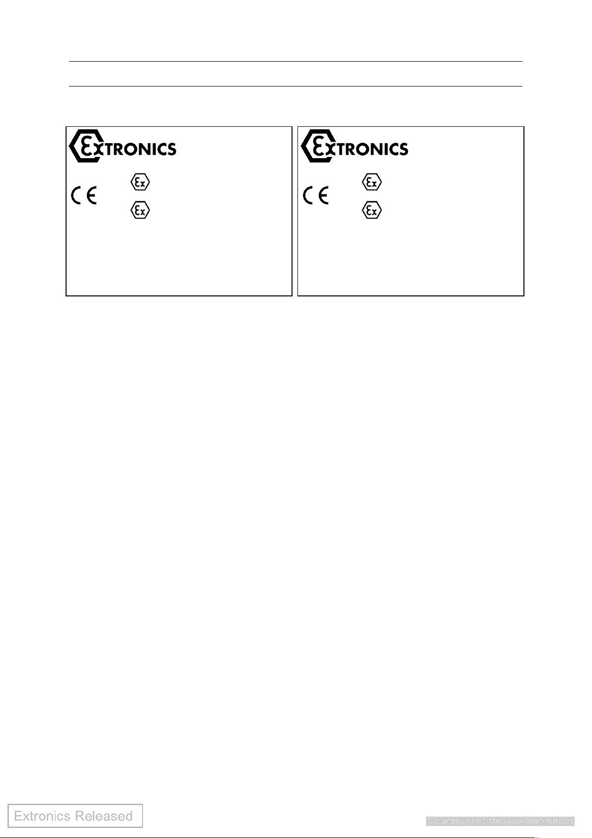
7 Label Drawing
EPSILON 08 ATEX 2394X
II 3G Ex nAnL IIC T3 (–40°C Ta +70°C)
EPSILON 08 ATEX 2395X
II 2D Ex tD A21 IP66 T82 (–40°C Ta + 70°C)
iWAP200
Date
Serial #
DO NOT OPEN WH ILE ENERGIZED
DO NOT OPEN WH EN AN EXPLOSIVE GAS/DUST ATMOSPHERE IS PRESENT
ENSURE GASKET IS FITTED BETWEEN BODY AND COVER
TO MAINTAIN IP RATING
Extronics Ltd 1 Dalton Way, Midpoint 1 8, Middlewich, Cheshire CW10 0HU UK
Tel: +44(0) 845 277 5000 Fax: +44 (0) 845 277 4000
E-mail: [email protected] W eb: www. extronics.com
xxxx
Voltage:
EPSILON 08 ATEX 2394X
II 3G Ex nAnL IIC T3 (–20°C Ta +70°C)
T4 (–20°C Ta + 65°C)
T5 (–20°C Ta +30°C)
EPSILON 08 ATEX 2395X
II 2D Ex tD A21 IP66 T82 (–40°C Ta + 70°C)
iWAP200
Date
Serial #
DO NOT OPEN WH ILE ENERGIZED
DO NOT OPEN WH EN AN EXPLOSIVE GAS/DUST ATMOSPHERE IS PRESENT
ENSURE GASKET IS FITTED BETWEEN BODY AND COVER
TO MAINTAIN IP RATING
Extronics Ltd 1 Dalton Way, Midpoint 1 8, Middlewich, Cheshire CW10 0HU UK
Tel: +44(0) 845 277 5000 Fax: +44 (0) 845 277 4000
E-mail: [email protected] W eb: www. extronics.com
xxxx
With Heaters
Witho ut Heaters
Page 21

8 Type Codes
iWA P2 00 Zone 2 A cc ess P oi nt Enclos ure iWAP200-[#1]-[#2]-[#3]-[#4]-[#5]-[#6]-[#7]-[#8]-[#9]
Specify option [#1] - Wireless Network Hardware
Hardware supplied by Customer* C
Hardware supplied by Extronics E
Specify option [#2] - Type Of Wireless Network Hardware
Cisco AP1242 Access Point (No heating/Cooling: -20oC to 45oC, with heating/cooling -40oC to 55oC) 6
Cisco AP1242 LAP Light Access Point (No heating/Cooling: -20oC to 45oC, with heating/cooling -40oC to 55oC) 7
Acksys WLG-LINK-OEM (No heating/Cooling: -20oC to 60oC, with heating/cooling -40oC to 70oC) 26**
Firetide 7000 Series MESH Router (No heating/Cooling: 0oC to 50oC, with heating/cooling -20oC to 60oC) 30
AeroScout Location Receiver (No heating/Cooling: 0oC to 50oC, with heating/cooling -40oC to 60oC) 31
Cisco AIR-CAP3502E / AIR-CAP3501E (No heating/Cooling: -20oC to 45oC, with heating/cooling -30oC to 55oC) 33
Aruba AP-92 (No heating/Cooling: 0oC to 40oC, with heating/cooling -40oC to 50oC) 42
Firetide 4500 Series Access Points (No heating/Cooling: 0oC to 40oC, with heating/cooling -20oC to 50oC) 43
**(Note: Acksys WLG-LINK-OEM is NOT currently compatible with an 802.3af POE input. For option #3 only AC or DC input may be
chosen)
*Extronics can supply the above wireless network hardware, alternatively you may wish to “free issue” one of the above solutions so that
we can factory fit it. New hardware n ot already on t he li st a bov e wi ll ne ed to be as s es sed and c ertif ie d to de te rmine i ts
suitabi li ty.
Please note that in order to meet the requirements of the certification Extronics has to take the internal PCB's from the Access Point
enclosure and make minor modifications to them. This will invalidate the warranty from the original manufacturer. If you wish the
wireless network hardware to have a 12 month warranty like the iWAP200 enclosure system is supplied with then Extronics must supply
the wireless hardware. Select order code E for [#1] if you require Extronics to supply the wireless network hardware.
Specify option [#3] - Power Supply
Universal 90-264VAC (If heater option [#7] selected, the unit cannot have a universal voltage, it will be either 115VAC or 230VAC) AC
24V DC DC
IEEE802.3af compliant Power-Over-Ethernet POE
Note: If AC option is selected, the unit can be powered by either AC supply or POE supply
Specify option [#4] - Ethernet Connection
10/100BaseT Ethernet on CAT5 copper C
Multimode 10/100BaseFX fibre with ST connector (Note : minimum ambient temperature 0oC without heaters) F
Single mode 100BaseLX-10 fibre with SC connector (Note: minimum ambient temperature 0oC without heaters) S
Specify option [#5] - Number of Antenna Outputs for Radio 1
0 o ff N -type c on ne ctor 0
1 o ff N -type c on ne cto r 1
2 o ff N -type c on ne cto r 2
3 o ff N -type c on ne cto r 3
0 o ff N -type c on ne cto r wi th surg e pro tect or 0S
1 o ff N -type c on ne cto r wi th surg e pro tect or 1S
2 o ff N -type c on ne cto r wi th surg e pro tect or 2S
3 o ff N -type c on ne cto r wi th surg e pro tect or 3S
Specify option [#6] - Number of Antenna Outputs for Radio 2
0 o ff N -type c on ne cto r 0
1 o ff N -type c on ne cto r 1
2 o ff N -type c on ne cto r 2
3 o ff N -type c on ne cto r 3
0 o ff N -type c on ne cto r wi th surg e pro tect or 0S
1 o ff N -type c on ne cto r wi th surg e pro tect or 1S
2 o ff N -type c on ne cto r wi th surg e pro tect or 2S
3 o ff N -type c on ne cto r wi th surg e pro tector 3S
Specify option [#7] - Enclosure Heating (not compatible with universal 90-264VAC or POE supplies)
No enclosure heating - T4/T5 temperature classification N
230 VA C enclosu re heatin g - T3 temp er ature c la ssifi cati on H1
115VAC en closu re h ea ting - T3 temp er at ur e classificati on H2
24V DC e nclosur e he ati ng - T 3 tempera tu re cl as si ficatio n H3
Specify option [#8] - Enclosure cooling (not compatible with POE supply)
No enclosure cooling N
Enclosure cooling fitted C
Specify option [#9] - Enclosure Cable Entry
Metal compression Cable glands fitted G
No Glands fitted, M20 entries provided for installer to provide own glands or blacking plugs/sockets N
Accessories
Pipe mount bracket kit to enable the unit to be fixed to a pipe or rectangular post. (2 kits required for complete fitment) iWAPMB01
Page 22
Operating Manual
22
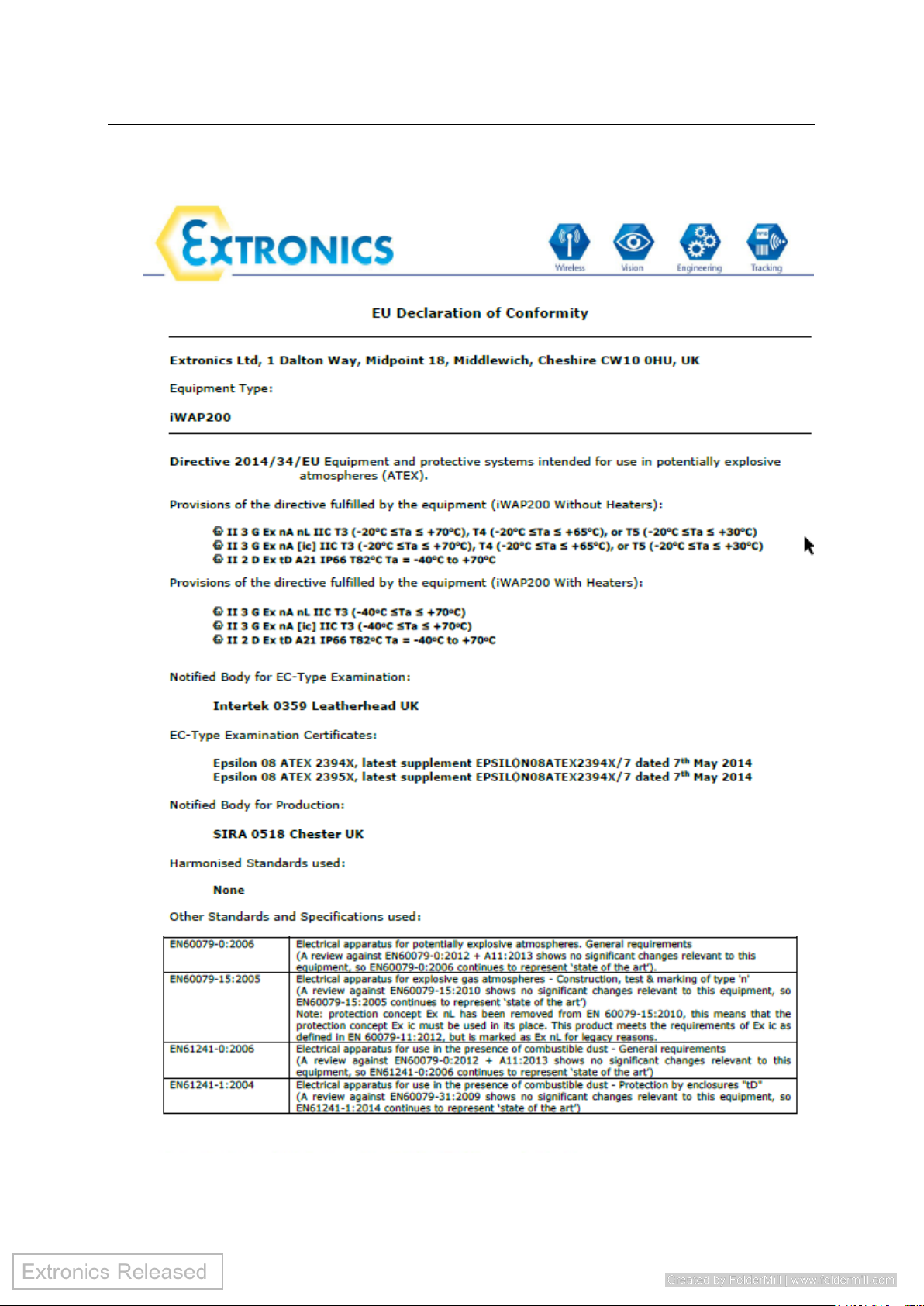
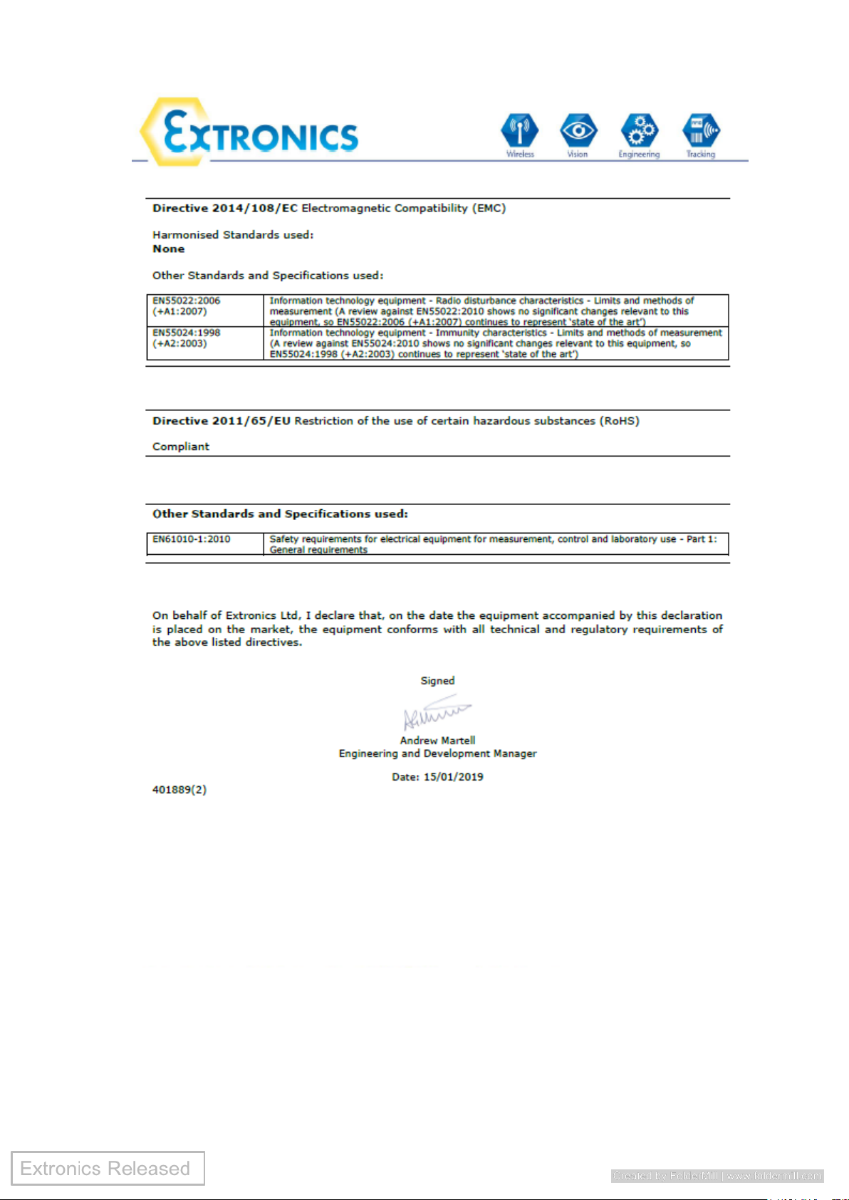
9 EU Declaration of Conformity
Page 23
Operating Manual
23
 Loading...