

Page 1
Operating Manual
iSOLATE501
Page 2

iSOLATE501 Operating Manual
Page 2 of 21
Document number 431569(4). Refer to Extronics DDM for release status.
This document is not to be modified without prior reference to an authorised person.
© Copyright Extronics Ltd, 2018
Page 3

iSOLATE501 Operating Manual
Page 3 of 21
Contents
1 Introduction .......................................................................................................... 4
2 Safety Information and Notes ............................................................................... 5
2.1 Storage of this Manual ................................................................................... 5
2.2 Special Conditions for Safe Use .................................................................... 5
2.3 Electrical Rating (MET) .................................................................................. 6
2.4 Approval Information (MET) ........................................................................... 6
2.5 List of Notes ................................................................................................... 6
3 Installation and Setting-to-Work ........................................................................... 8
3.1 Input / Output parameters .............................................................................. 8
3.2 iSOLATE501 Mounting and Earthing ............................................................. 9
3.3 RF Connections ........................................................................................... 12
3.4 Connection to a transmitter .......................................................................... 12
3.5 Connection to an antenna ............................................................................ 13
4 Intended Purpose Usage .................................................................................... 15
4.1 Transportation and Storage ......................................................................... 15
4.2 Authorized Persons ..................................................................................... 15
4.3 Cleaning and Maintenance .......................................................................... 16
4.4 Safety Precautions ....................................................................................... 16
4.5 Cleaning and Maintenance Intervals ............................................................ 16
4.6 Aggressive substances and environments ................................................... 16
4.7 Exposure to external stresses ...................................................................... 17
5 Technical Data ................................................................................................... 18
6 Label Drawing .................................................................................................... 19
7 EU Manufacturers Declaration ........................................................................... 20
Page 4

iSOLATE501 Operating Manual
Page 4 of 21
1 Introduction
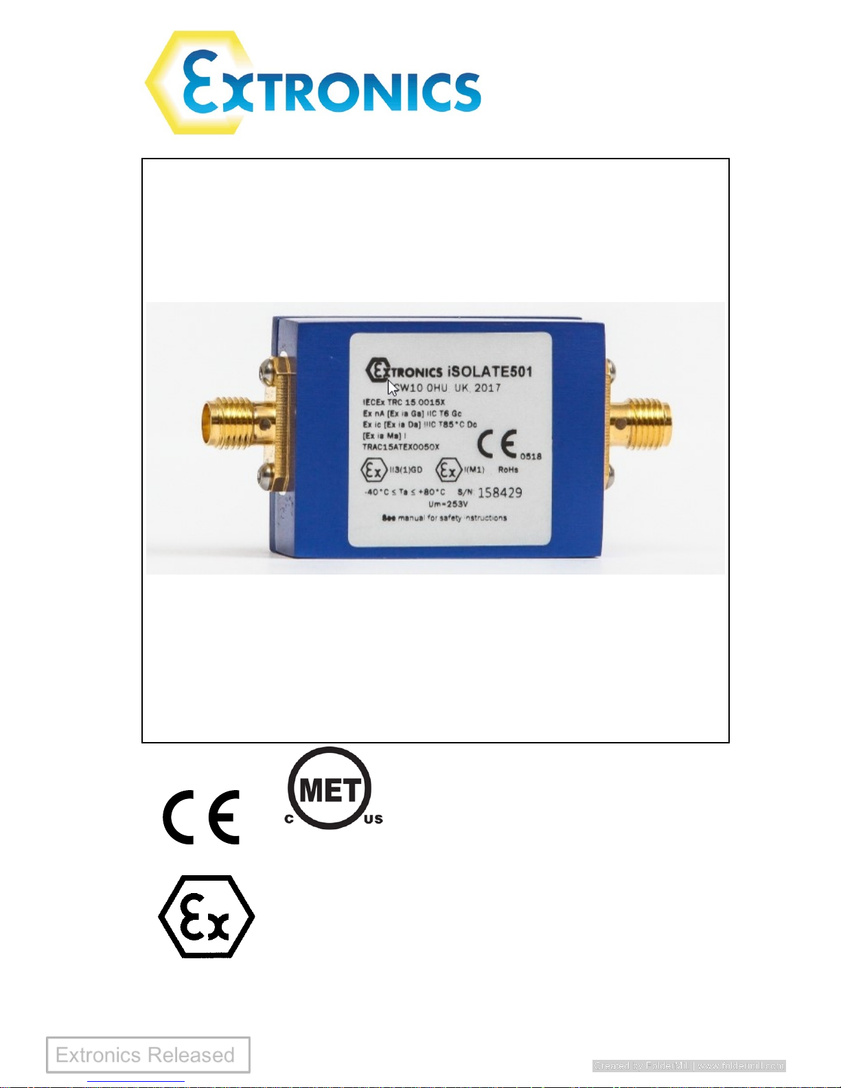
The iSOLATE501 is an ATEX / IECEx / MET approved RF galvanic isolator.
ATEX/IECEx:
For Group I mining applications, the iSOLATE501 must be installed in the safe
area. For other hazardous area applications, the iSOLATE501 must be mounted in a
suitably approved hazardous area enclosure with minimum IP54 rating while situated
in hazardous gas atmospheres and must be mounted in a suitably approved
hazardous area enclosure with minimum IP54 rating while situated in hazardous dust
atmospheres.
The iSOLATE501 galvanically isolates circuits in the hazardous area from potentially
incendive faults using the intrinsic safety concept. When the iSOLATE501 is connected
to source equipment with Um ≤ 253V, it blocks DC, low-frequency AC and transient
faults from appearing at the output terminal. The iSOLATE501 will allow RF signals at
frequencies within its wide pass-band (120MHz - 8GHz) to pass through to its output;
these RF signals are incapable of causing ignition if their power level is within that
specified in IEC60079-0:2011 Table 4.
The galvanically isolated RF output of the iSOLATE501 allows users to use non-
hazardous area certified antennas* with their wireless hardware, such as the Extronics
iANT200 range of high quality rugged outdoor antennas.
* Antennas not listed in the Extronics range must be assessed by the user to ensure that they meet the
mechanical requirements for the installation of equipment in hazardous areas, do not contain active
elements, etc.
Page 5

iSOLATE501 Operating Manual
Page 5 of 21
2 Safety Information and Notes
2.1 Storage of this Manual
Keep this user manual safe and in the vicinity of the device. All persons who have to
work on or with the device should be advised on where the manual is stored.
2.2 Special Conditions for Safe Use
2.2.1 ATEX/IECEx
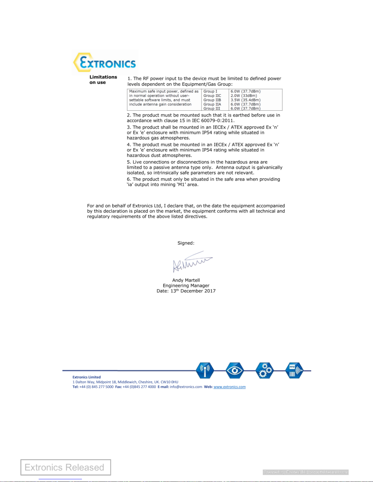
2.2.1.1 The RF power input to the device must be limited to defined power levels
dependent on the Equipment/Gas Group:
Maximum safe input power, defined as in
normal operation without user-settable
software limits, and must include antenna
gain consideration.
Group I
6.0W (37.7 dBm)
Group IIC
2.0W (33 dBm)
Group IIB
3.5W (35.4 dBm)
Group IIA
6.0W (37.7 dBm)
Group III
6.0W (37.7 dBm)
2.2.1.2 The product must be mounted such that it is earthed before use in accordance
with clause 15 in IEC 60079-0:2011.
2.2.1.3 The product shall be mounted in an IECEx / ATEX approved Ex ‘n’ or Ex ’e’
enclosure with minimum IP54 rating while situated in hazardous gas
atmospheres.
2.2.1.4 The product must be mounted in an IECEx / ATEX approved Ex ‘n’ or Ex ’e’
enclosure with minimum IP54 rating while situated in hazardous dust
atmospheres.
2.2.1.5 Live connections or disconnections in the hazardous area are limited to a passive
antenna type only. Antenna output is galvanically isolated, so intrinsically safe
parameters are not relevant.
Page 6

iSOLATE501 Operating Manual
Page 6 of 21
2.2.1.6 The product must only be situated in the safe area when providing ‘ia’ output into
mining ‘M1’ area.
2.2.2 MET
2.2.2.1 The product shall always be mounted within an approved minimum NEMA 4
enclosure complying with ANSI/UL 50E as a condition of safe use.
2.3 Electrical Rating (MET)
Um=253Va.c
Class I, Division 2, Class III, Divisions 1 and 2, Groups A to G, T4
Class I, II, III, Division 1. Groups A to G (Associated IS Equipment)
Class I, Zone 0, Group IIC, T4 (Associated IS Equipment)
Ta = 60oC to 80oC
2.4 Approval Information (MET)
The iSOATE501 product are approved to the following standards:
ANSI/ISA 12.12.01,
UL913,
UL60950-1 / CSA C22.2 No. 60950-1,
CAN/CSA-C22.2 No. 60079-0:11,
CAN/CSA-C22.2 No. 60079-11:11
2.5 List of Notes
The notes supplied in this chapter provide information on the following.
• Danger / Warning.
o Possible hazard to life or health.
• Caution
o Possible damage to property.
Page 7

iSOLATE501 Operating Manual
Page 7 of 21
• Important
o Possible damage to enclosure, device or associated equipment.
• Information
o Notes on the optimum use of the device
Warning! For Group I mining applications, the iSOLATE501 must only be
installed in the safe area.
For other hazardous area applications, the product shall be
mounted in a suitably approved hazardous area enclosure with
minimum IP54 rating while situated in hazardous gas atmospheres
and shall be mounted in a suitably approved hazardous area
enclosure with minimum IP54 rating while situated in hazardous
dust atmospheres.
Warning! For MET the product shall always be mounted within an approved
minimum NEMA 4 enclosure complying with ANSI/UL 50E as a
condition of safe use.
Warning! The RF threshold power must be limited to the levels defined in
IEC60079-0:2011 Table 4; the iSOLATE501 does not provide any inband RF power limitation. See section 3.4.1 for details.
Warning! To maintain safe operation, the iSOLATE501 MUST be earthed.
Refer to Section 3.2 for details.
Warning! The antennas connected to the iSOLATE501 must be installed in
accordance with the earthing requirements of IEC60079-14:2014
clause 16.2.3.
Warning! The iSOLATE501 does not contain any user-serviceable parts. Any
attempt to open the unit may render it unsafe and will void the
warranty.
Page 8

iSOLATE501 Operating Manual
Page 8 of 21
3 Installation and Setting-to-Work
3.1 Input / Output parameters
The iSOLATE501 has the following input/output parameters:
Um=253V
rms
RF threshold Output Power (expressed in dBi) = Effective RF Transmitter Power Input
into the iSOLATE501, less insertion loss of the iSOLATE501 plus the antenna gain.
The maximum permitted RF Threshold Output Power is dependent upon the
Equipment Group in which the antenna is located, as defined in the following table.
See section 3.4 for further details.
ATEX/IECEx
Equipment
Group
Maximum RF
Threshold Power
(Watts)
Maximum RF
Threshold Power
(dBm)
Mining Group I
6
37.7
Gas Group IIA
6
37.7
Gas Group IIB
3.5
35.4
Gas Group IIC
2
33
Dust Group III
6
37.7
Table 1: Maximum permitted RF Threshold Power
Page 9

iSOLATE501 Operating Manual
Page 9 of 21
3.2 iSOLATE501 Mounting and Earthing
Warning! For Group I mining applications, the iSOLATE501 must only be
installed in the safe area.
For other hazardous area applications, the product shall be
mounted in a suitably approved hazardous area enclosure with
minimum IP54 rating while situated in hazardous gas atmospheres
and shall be mounted in a suitably approved hazardous area
enclosure with minimum IP54 rating while situated in hazardous
dust atmospheres.
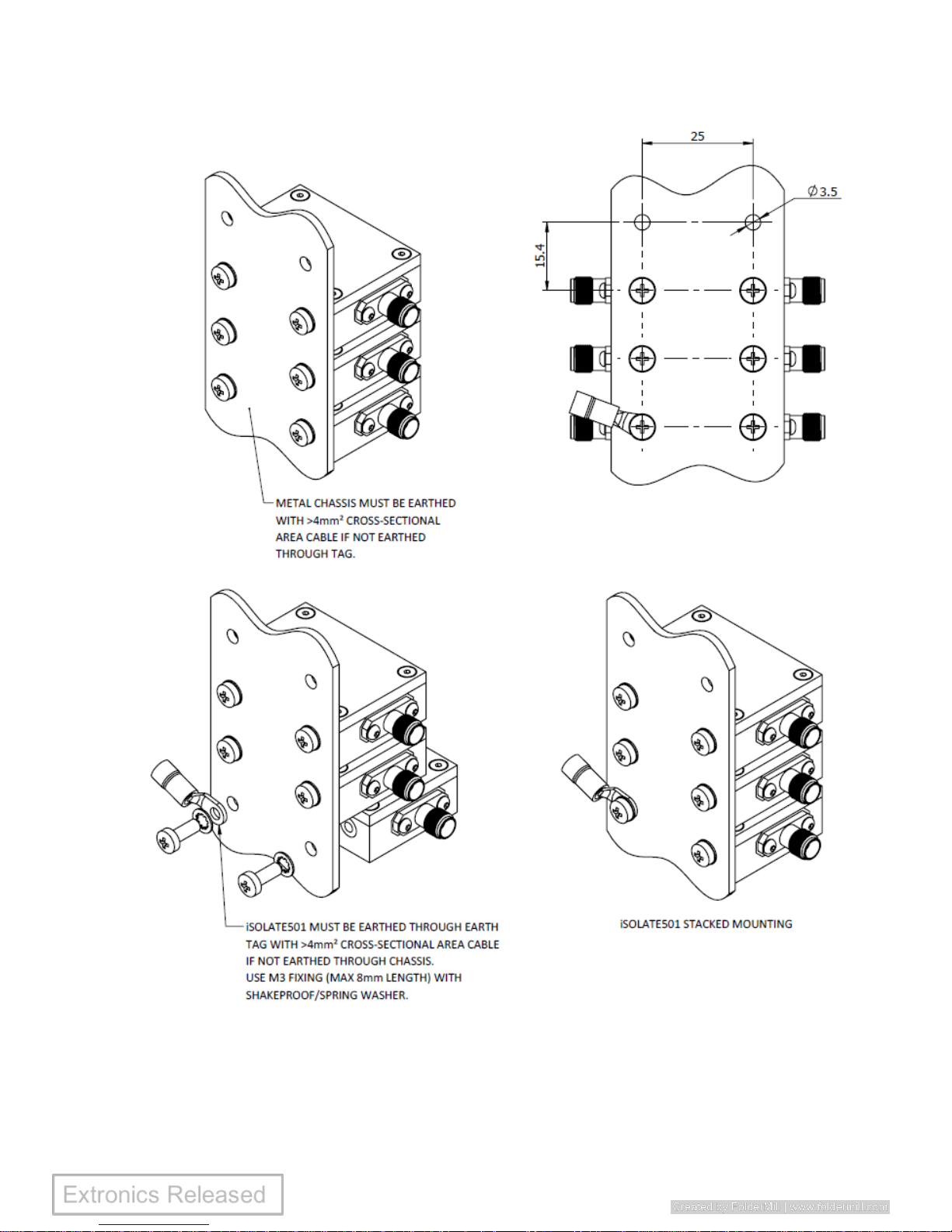
Warning! To maintain safe operation the iSOLATE501 MUST be earthed - see
Figure 1.
Page 10
iSOLATE501 Operating Manual
Page 10 of 21
Figure 1: Earthing and Mounting of iSOLATE501
Page 11
iSOLATE501 Operating Manual
Page 11 of 21
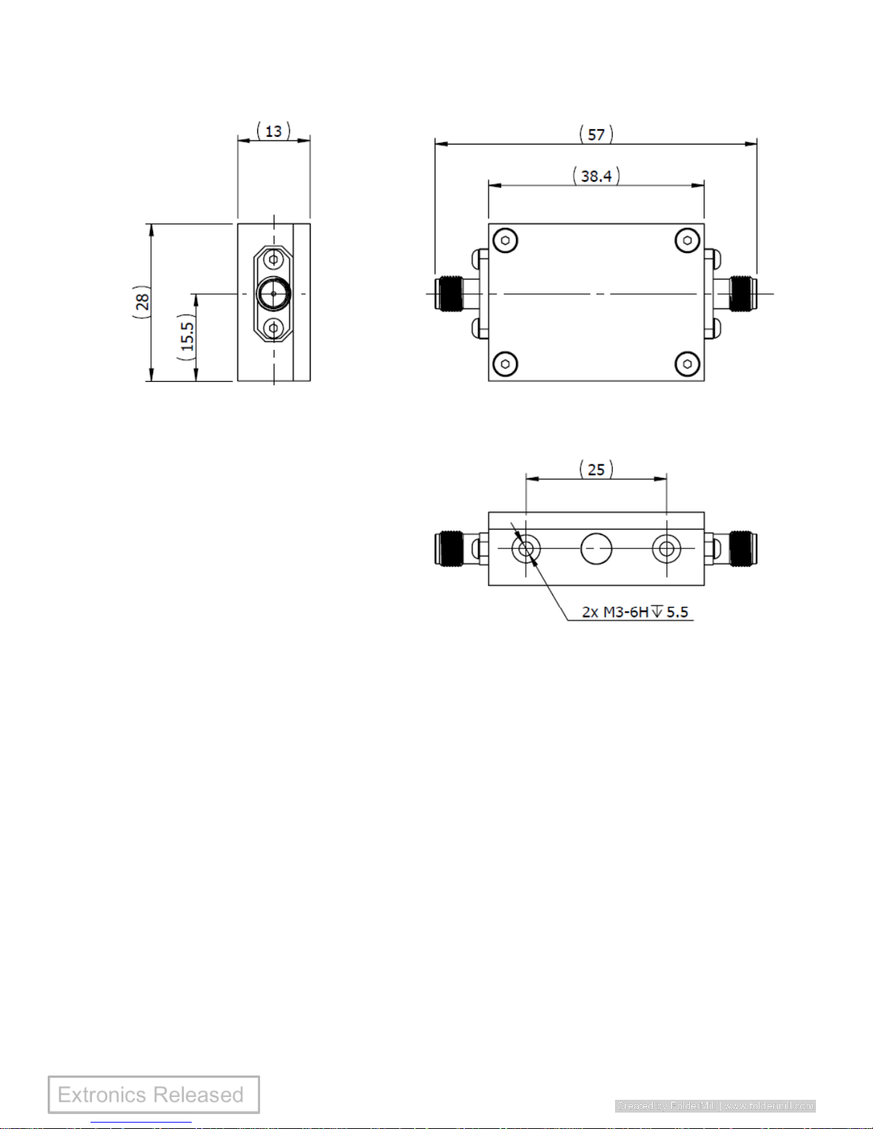
Figure 2: iSOLATE501 Dimensions
Page 12

iSOLATE501 Operating Manual
Page 12 of 21
3.3 RF Connections
The iSOLATE501 is fitted with two SMA female connectors, one at each end. The
iSOLATE501 is a totally bi-directional device, and therefore either connector can
function as the input or output.
3.4 Connection to a transmitter
The iSOLATE501 may be connected to any radio transmitter operating within its pass-
band. It is the responsibility of the installer to ensure that the following requirements
are met:
1. The RF threshold power radiated from the antenna must be limited to the levels
shown in Table 1. The calculation of this should take into account the power
output of the transmitter (as specified by the manufacturer in normal operation)
and the gain of the antenna. It is permissible to consider losses in the cable in
this calculation.
2. It is permissible for the maximum power output of the transmitter to be limited
by a software setting, but it must not be possible for the end-user to override
this.
3. Consideration of fault conditions in the transmitter is not necessary when
calculating RF threshold power. The transmitter’s maximum RF output power
should be taken from the transmitter manufacturer’s datasheet in normal
operation, i.e. the maximum value of RF output power than can be set by the
user.
3.4.1 Example of RF threshold power calculation
The following example shows how the RF threshold power may be calculated:
Page 13

iSOLATE501 Operating Manual
Page 13 of 21
Maximum transmitter output power (from transmitter datasheet) = 20dBm (100mW)
Coaxial cable loss = 2dB
Antenna gain = 5dBi
Threshold power = 20dBm – 2dB + 5dBi
Threshold power = 23dBm (200mW)
3.5 Connection to an antenna
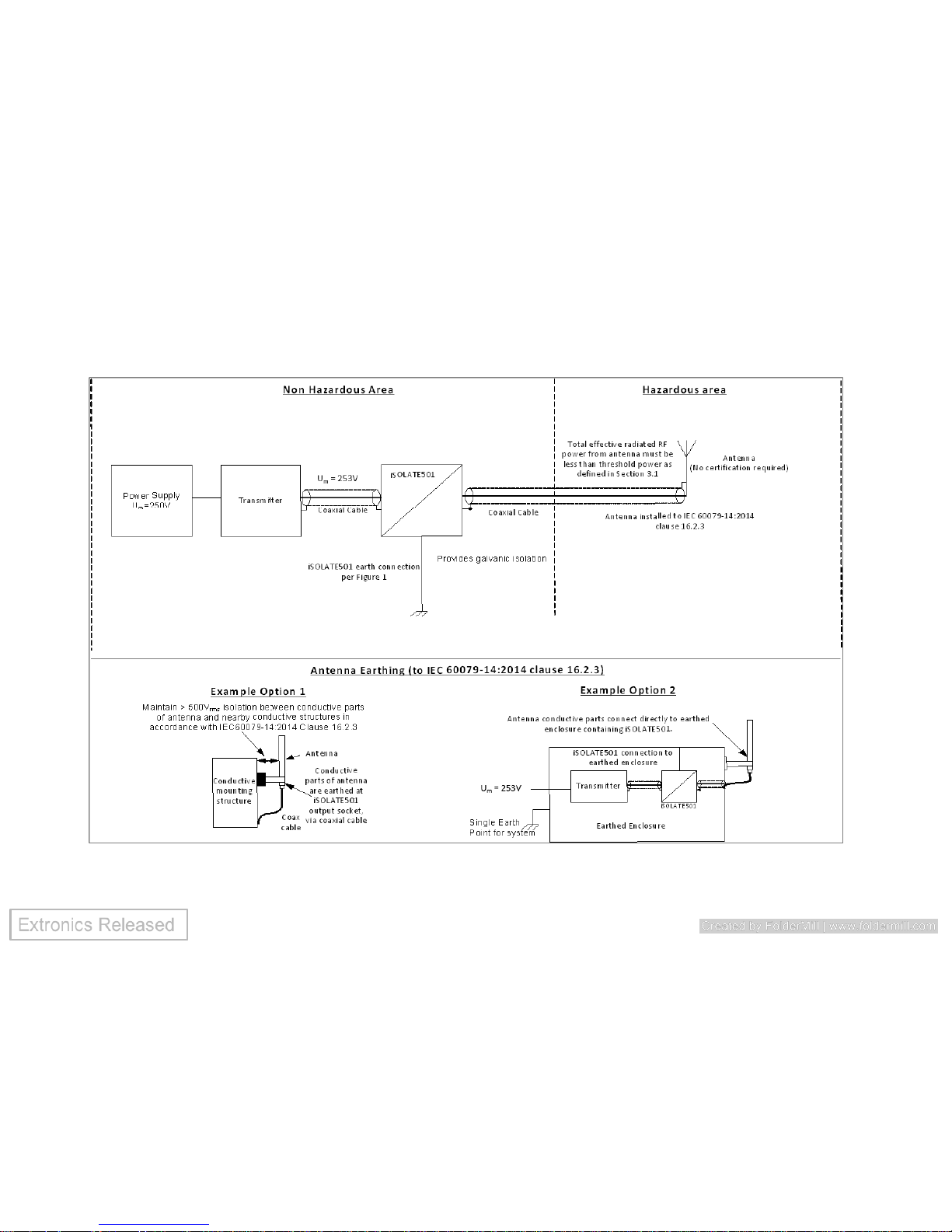
Warning! The antennas connected to the iSOLATE501 must be installed in
accordance with the earthing requirements of IEC60079-14:2014
clause 16.2.3.
3.5.1 Example 1
The conductive parts of the antenna must be isolated by at least 500Vrms from nearby
conductive structures, to prevent hazardous earth currents from flowing in the coaxial
cable. It is the responsibility of the installer to perform the necessary tests to verify
this.
Note: As the iSOLATE501 must be earthed, the return path of the RF output connector
will also be at earth potential. Therefore the verification of isolation of the antenna from
earth must only be carried out when the antenna and iSOLATE501 are not connected.
3.5.2 Example 2
When the iSOLATE501 is installed inside an earthed enclosure, which has a single
connection to earth, and the antennas are mounted to this enclosure, the antennas do
not require 500V isolation from earth (as it may be earthed through the enclosure to
the single earth point along with the iSOLATE501)
For more guidance consult IEC60079-14:2014 clause 16.2.3
Page 14
iSOLATE501 Operating Manual
Page 14 of 21
Figure 3: Electrical Installation
Page 15
iSOLATE501 Operating Manual
Page 15 of 21
4 Intended Purpose Usage
Important Before setting the units to work, read the technical
documentation carefully.
Important The latest version of the technical documentation or the
corresponding technical supplements is valid in each
case.
The iSOLATE501 is built using modern components and is extremely
reliable in operation; however it must only be used for its intended purpose.
Please note that the intended purpose also includes compliance with the
instructions issued by the manufacturer for installation, setting up and
service.
Any other use is regarded as conflicting with the intended purpose. The
manufacturer is not liable for any subsequent damage resulting from such
inadmissible use. The user bears the sole risk in such cases.
4.1 Transportation and Storage
All iSOLATE501 devices must be so transported and stored that they are not
subjected to any excessive mechanical stresses.
4.2 Authorized Persons
Only persons trained for the purpose are authorized to handle the
iSOLATE501; they must be familiar with the unit and must be aware of the
Page 16

iSOLATE501 Operating Manual
Page 16 of 21
regulation and provisions required for explosion protection as well as the
relevant accident prevention regulations.
4.3 Cleaning and Maintenance
The iSOLATE501 and all its components require no maintenance. All work
on the iSOLATE501 by personnel who are not expressly qualified for such
activities will cause the Ex approval and the guarantee to become void.
4.4 Safety Precautions
Important For the installation, maintenance and cleaning of the
units, it is absolutely necessary to observe the applicable
regulations and provisions concerned with explosion
protection (IEC 60079-14), as well as the Accident
Prevention Regulations.
4.5 Cleaning and Maintenance Intervals
The cleaning intervals depend on the environment where the system is
installed.
4.6 Aggressive substances and environments
The iSOLATE501 is not designed to come into contact with aggressive
substances or environments, please be aware that additional protection may
be required.
Page 17

iSOLATE501 Operating Manual
Page 17 of 21
4.7 Exposure to external stresses
The iSOLATE501 is not designed to be subjected to excessive stresses e.g.
vibration, heat, impact. Additional protection is required to protect against
these external stresses.
The iSOLATE501 will require additional protection if it is installed in a
location where it may be subjected to damage.
Page 18
iSOLATE501 Operating Manual
Page 18 of 21
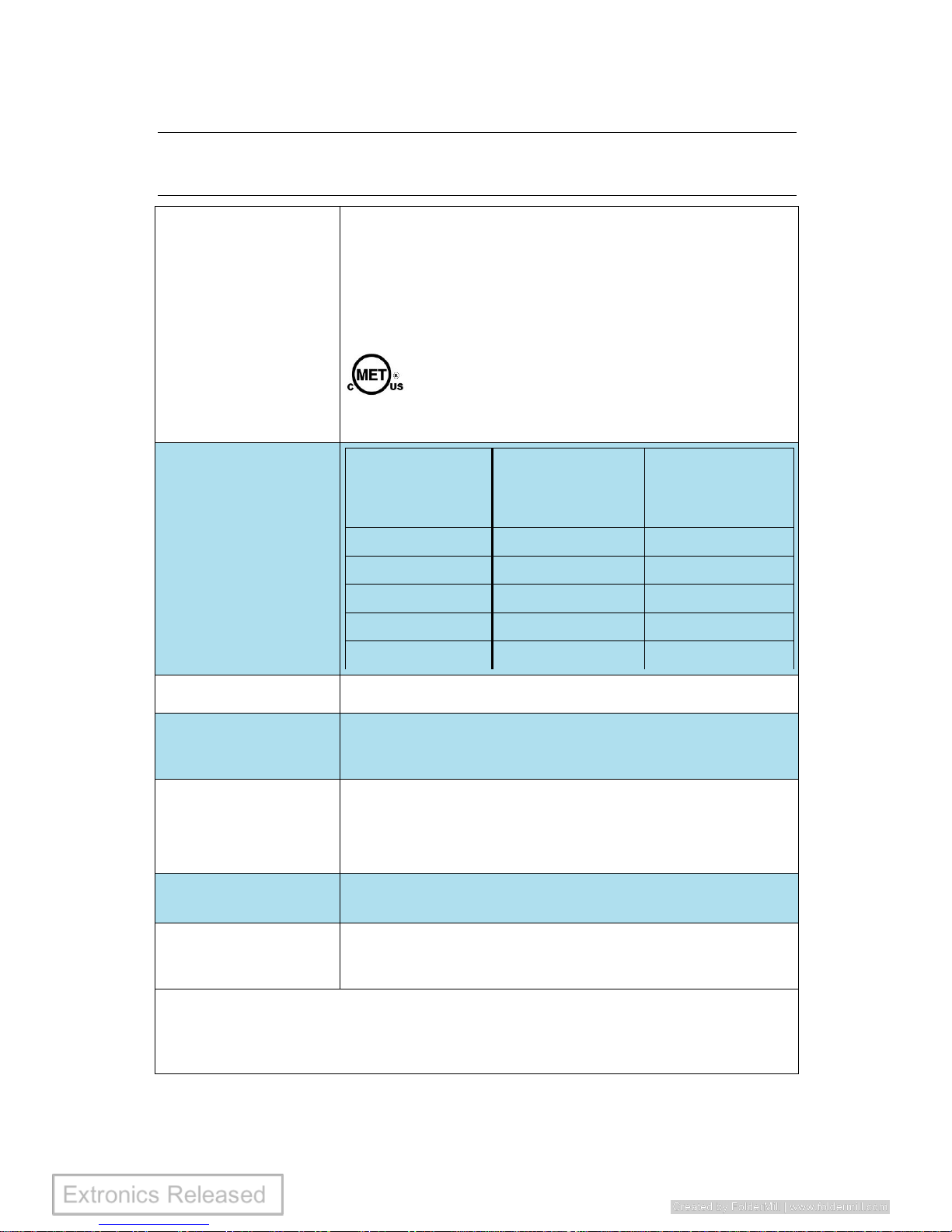
5 Technical Data
Certification Type
Ex nA [Ex ia Ga] IIC T6 Gc
Ex ic [Ex ia Da] IIIC T85°C Dc
[Ex ia Ma] I
II 3 (1) G D
I (M1)
Class I & II Division 2, Class III Divisions 1 & 2
Groups A - G
Class I, Zone 0, Group IIC
Maximum Input /
Output Power
ATEX/IECEx
Equipment
Group
Maximum RF
Threshold Power
(Watts)
Maximum RF
Threshold Power
(dBm)
Mining Group I
6
37.7
Gas Group IIA
6
37.7
Gas Group IIB
3.5
35.4
Gas Group IIC
2
33
Dust Group III
6
37.7
Enclosure Material
Aluminium
Environmental
Ambient temperature: -40ºC to +80ºC
Relative humidity; 0 to 95%, non-condensing
Dimensions
(w x h x d)
Weight
38.4 x 28 x 13 mm (57 mm including SMA connectors)
Approx 37g
RF Connections
SMA Female
Certification
TRAC15ATEX0050X, IECEx TRC 15.0015X,
MET NRTLC88100
1
Please note that it is the customer’s responsibility to ensure the maximum
values for RF Threshold power as per Table 4.0 of IEC 60079-0:2011 are not
exceeded. The maximum RF output of the wireless transmitter and antenna gain
must be considered when installing equipment. Refer to manual for full details.
Page 19
iSOLATE501 Operating Manual
Page 19 of 21
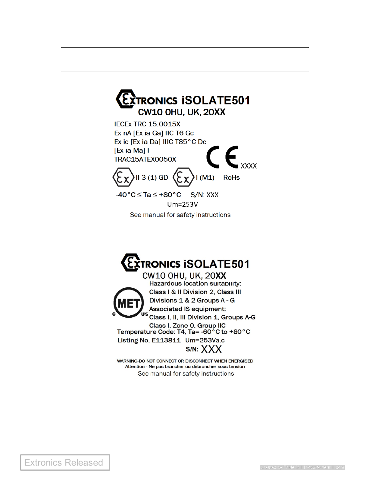
6 Label Drawing
ATEX/IECEx Label:
Where XXXX = Notified Body Number
MET Label:
Page 20
iSOLATE501 Operating Manual
Page 20 of 21
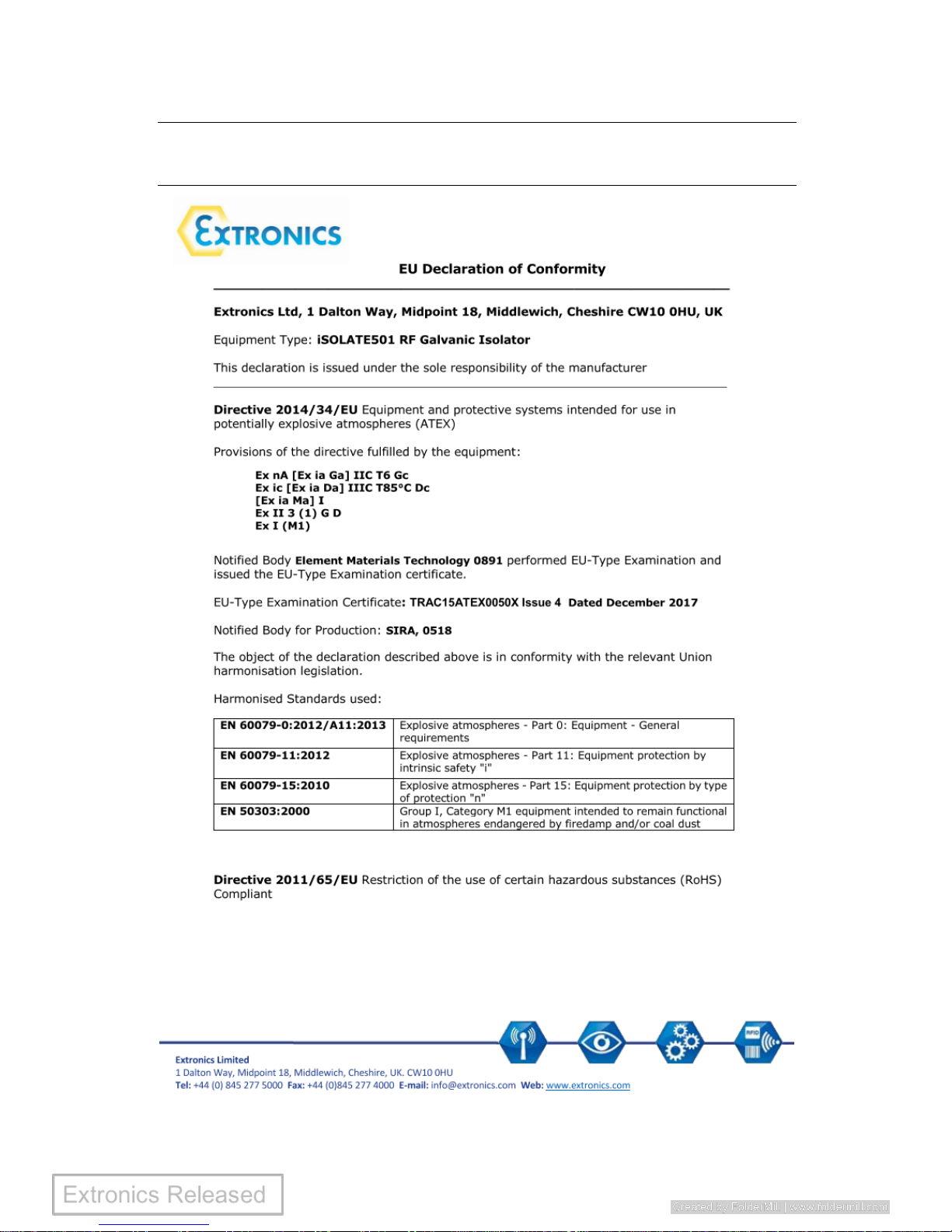
7 EU Manufacturers Declaration
Page 21
iSOLATE501 Operating Manual
Page 21 of 21
 Loading...