

Operating Manual
iANT100, iANT101

Operating Manual
2
This page is intentionally left blank.
Document Number 314666(8)
©2018 Extronics Limited. This document is Copyright Extronics limited.
Extronics reserve the right to change this manual and its contents without notice, the latest
version applies.

Operating Manual
3
Contents
1 Introduction .......................................................................................................... 4
1.1 Antenna Profile .............................................................................................. 4
2 Safety Information and Notes .............................................................................. 5
2.1 Storage of this Manual ................................................................................... 5
2.2 Special Conditions for Safe Use .................................................................... 5
2.2.1 ATEX/IECEx ........................................................................................... 5
2.3 List of Notes .................................................................................................. 5
3 General information ............................................................................................. 7
3.1 Installation and Function ................................................................................ 7
3.1.1 Parts Enclosed ........................................................................................ 7
3.1.2 Antenna Installation Recommendations .................................................. 7
3.2 Optional Accessories ..................................................................................... 8
3.2.1 iANTMB01 ............................................................................................... 8
3.2.2 iANTMB02 ............................................................................................... 9
3.2.3 iANTMB03 ............................................................................................... 9
3.2.4 iANTMB04 ............................................................................................. 10
3.2.5 iANTMB05 ............................................................................................. 10
3.2.6 iANTMB06 ............................................................................................. 11
4 Technical Specification ...................................................................................... 12
4.1 Antenna polar patterns and VSWR Plots ..................................................... 12
4.1.1 iANT100/101 2.4 GHz/5 GHz ................................................................ 12
4.1.2 iANT100 GSM Quad Band .................................................................... 13
4.1.3 iANT101 437/458.5/466MHz ................................................................. 14
4.2 iANT100 Specifications .............................................................................. 15
4.3 iANT100 Cable Loss .................................................................................... 16
4.4 iANT101 Specifications ............................................................................... 16
4.5 iANT101 Cable Loss .................................................................................... 17
5 Intended Purpose Usage ................................................................................... 18
5.1 Transportation and Storage ......................................................................... 18
5.2 Cleaning and Maintenance .......................................................................... 18
6 Fitting of Exd Antenna Cable Gland on iANT100 .............................................. 19
7 Type Codes ....................................................................................................... 23
7.1 iANT100 ...................................................................................................... 23
7.2 iANT101 ...................................................................................................... 24
8 EC Declaration of Conformity ............................................................................ 25
9 ATEX & IECEx CERTIFICATION ................................................................ ...... 27
10 Warranty Information ...................................................................................... 34

Operating Manual
4
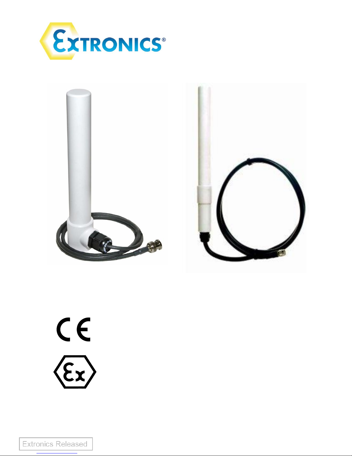
1 Introduction
1.1 Antenna Profile
The iANT100 and iANT101 are increased safety antennas and have been
designed and approved by ATEX and IECEx for use in Zone 1 / 21 & Zone 2/22
Hazardous Area Environments.
The iANT100 and iANT101 are optimised for use in WLAN installations in the 2.4GHz
and 5 GHz spectrums for IEEE802.11 a/b/g wireless networks or 2.4GHz and 5GHz
wireless MESH Ethernet networks.
These devices can be used with explosion proof Access Points such as the Extronics
iWAP101 iWAP103 or an Access Point installed in a safe area and just the antenna
installed in the hazardous area.
The units are explosion protected in accordance with IEC 60079-0:2007-10 edition 5,
IEC 60079-31:2008 edition 1, IEC60079-7:2006-07 edition 4, EN 60079-0:2009, EN
60079-7:2007.
The device is certified as:
II 2 GD
Ex e IIC T6 Gb (Ta = -40°C to 60°C)
Ex t IIIC T85°C Db IP66.
It can operate in areas classified as Zone 1, gas and dust with a temperature class of
T6 with a maximum temperature of 60oC
The minimum permissible ambient temperature is -40oC
The maximum permissible ambient temperature is 60oC
Operating Manual
5
2 Safety Information and Notes
2.1 Storage of this Manual
Keep this user manual safe and in the vicinity of the antenna. All persons who have to work
on or with the controller should be advised on where the manual is stored.
2.2 Special Conditions for Safe Use
2.2.1 ATEX/IECEx
• If terminated in the hazardous area, the flying lead shall be installed in an
appropriately-certified enclosure. An example would be termination inside a
flameproof enclosure via a suitable certified flameproof gland.
• The threshold power of the antenna shall be limited to 2 (two) watts when the
antenna gain is taken into account. Programmable or software control
intended for setting by the user is not permitted.
2.3 List of Notes
The notes supplied in this chapter provide information on the following.
• Danger / Warning.
o Possible hazard to life or health.
• Caution
o Possible damage to property.
• Important
o Possible damage to the device, or associated equipment.
• Information
o Notes on the optimum use of the device
Warning! The iANT100/iANT101 enclosure is an electrostatic charging hazard;
clean only with a damp cloth
Important The iANT100/iANT101 may be used in zones 1 and 2 with flammable
gases and vapours with apparatus groups IIA, IIB & IIC and with all
temperature classes.
Important The iANT100/iANT101 may also be used in zones 21 and 22 with all
flammable dusts compatible with the maximum surface temperature of
60C. The appropriate safety margin should be applied
Important The iANT100/iANT101 is only certified for use in ambient temperatures in
the range -40oC to +60oC and should not be used outside this range
Operating Manual
6
Important The equipment has not been assessed as a safety-related device (as
referred to by Directive 94/9/EC Annex II, clause 1.5
Important Installation of this equipment shall be carried out by suitably trained
personnel in accordance with the applicable code of practice (EN 60079-
14).
Important If terminated in the hazardous area, the flying lead shall be installed in an
appropriately-certified enclosure. An example would be termination
inside a flameproof enclosure via a suitable certified flameproof gland.
Important The iANT100/iANT101 and associated wiring should be periodically
inspected for damage, in accordance with the applicable code of practice
(EN 60079-17)
Important Repair of the iANT shall only be carried out by the manufacturer:
The antenna contains no user-serviceable parts
Warning The maximum radiated power shall not exceed 2 W EIRP
Operating Manual
7
3 General information
3.1 Installation and Function
3.1.1 Parts Enclosed
iANT100
• 1 x Antenna with 1mtr / 5mtr cable
• 1 x M6 x 10 slotted machine screw
• 1 x M6 lock washer
• 1 x Antenna Bracket
• 2 x 1 ¼” x 8 Wood Screws
• 2 x 6mm red rawl plugs
• 2 x self adhesive nylon blocks
• 2 x cable ties
iANT101
• 1 x Antenna with Cable as Ordered
• 1 x Antenna Pipe Mounting Bracket
If any Part is damaged or missing, contact Extronics Ltd
Warning Ensure that the M6 screw used to affix the iANT100 antenna does not
protrude more than 10mm into the antenna through the attachment
bracket. Protrusion greater than 10mm will cause damage to the
antenna.
3.1.2 Antenna Installation Recommendations
It is recommended that the antennas be mounted at least 204mm (8") away from any
metal objects e.g. metal clad walls or girders.
The antennas should be mounted at least 600mm (24") apart for optimal
performance, but will perform well closer together.
Information The iANT100 has optional brackets which allow the antenna to be
mounted directly to Extronics Range of hazardous area access points
Information The iANT101 is supplied with a pipe mounting bracket
Information It is impossible for the straight or right-angled N-type connector fitted to
the iANT100 to pass through an M20 gland entry. Either a larger entry
(for example an M25) should be used, or the connector should be fitted
after gland installation. Select either the gland reducer option or the
connector supplied separately option for the iANT100 as appropriate.
Information It is impossible for the straight N-type connector fitted to the iANT101 to
pass through an M20 gland entry. Either a larger entry (for example an
M25) should be used, or the connector should be fitted after gland
installation. Select either the gland reducer option or the connector
supplied separately option for the iANT101 as appropriate.

Operating Manual
8
Information It is impossible for the right-angled N-type connector fitted to the
iANT101 to pass through an M25 gland entry. Either a larger entry (for
example an M30) should be used, or the connector should be fitted after
gland installation. Select either the connector supplied separately option
for the iANT101, or use a larger entry as appropriate.
3.2 Optional Accessories
3.2.1 iANTMB01
316L stainless steel wall mount bracket assembly for iANT101 antenna.
This bracket is fitted away from the iWAP enclosure.
Operating Manual
9
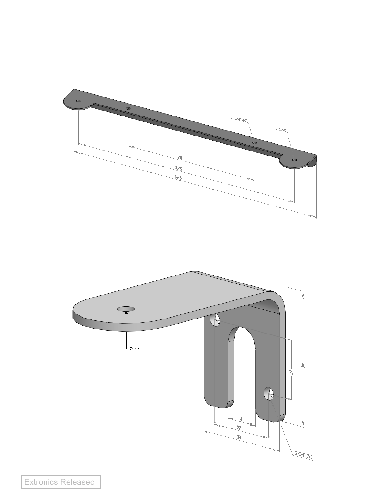
3.2.2 iANTMB02
316L stainless steel bracket kit, 365mm length, for two iANT100 antennas.
This bracket can be fitted onto or away from the iWAP enclosure.
3.2.3 iANTMB03
316L stainless steel wall mount bracket kit for iANT100 antenna.
This bracket is fitted away from the iWAP enclosure.

Operating Manual
10
3.2.4 iANTMB04
316L stainless steel ceiling mount bracket kit for iANT100 antenna.
This bracket is fitted away from the iWAP enclosure.
3.2.5 iANTMB05
316L stainless steel bracket kit, 365mm length, for three iANT100 antennas.
This bracket can be fitted onto or away from the iWAP enclosure.

Operating Manual
11
3.2.6 iANTMB06
316L stainless steel bracket kit, 430mm length, for three iANT100 antennas.
This bracket can be fitted onto or away from the iWAP enclosure.

Operating Manual
12
4 Technical Specification
4.1 Antenna polar patterns and VSWR Plots
4.1.1 iANT100/101 2.4 GHz/5 GHz
iANT100/101 2.4GHz E Plane Pattern Vertical Free
Space 3dB Beam-Width Approx 34
iANT100/101 2.4 GHz H-Plane Pattern Vertical Free
Space Omni-Directional
iANT100/101 5 GHz E Plane Pattern Vertical Free Space
3dB Beam-Width Approx 16
iANT100/101 5 GHz H-Plane Pattern Vertical Free
Space Omni-Directional

Operating Manual
13
iANT100/101 2.4GHz VSWR Plot
<1.8:1 2350—2550 MHz
iANT100/101 5GHz VSWR
<2:1 5000—6000 MHz
4.1.2 iANT100 GSM Quad Band
iANT100 GSM Quad Band E Plane Pattern
Vertical Free Space Beam-Width Approx 80
iANT100 GSM Quad Band H-Plane Pattern Vertical Free
Space Omni-Directional

Operating Manual
14
iANT100 GSM Quad Band VSWR Plot
<2:1 1750-1850MHz
iANT100 GSM Quad Band VSWR Plot
<2:1 860- 940 MHz
4.1.3 iANT101 437/458.5/466MHz
iANT101 437/458.5/466MHz
E Plane Pattern
Vertical Free Space Beam-Width Approx 80
iANT101 437/458.5/466MHz
H-Plane Pattern Vertical Free Space
Omni-Directional

Operating Manual
15
4.2 iANT100 Specifications
Parameter
iANT100-24
iANT100-58
iANT100-GSM-QB
Power
Max power 1 Watt continuous
ATEX: Maximum threshold power
must not exceed 2W EIRP when
taking antenna gain into account.
Software RF Power control settable by
the user is not permitted
Max power 1 Watt continuous
ATEX: Maximum threshold power
must not exceed 2W EIRP when
taking antenna gain into account.
Software RF Power control settable by
the user is not permitted
Max power 1 Watt continuous
ATEX: Maximum threshold power must
not exceed 2W EIRP when taking
antenna gain into account. Software RF
Power control settable by the user is
not permitted
Dimensions
210mm Length, 38mm Diameter
210mm Length, 38mm Diameter
210mm Length, 38mm Diameter
Weight
365g
365g
365g
Connections
Straight Reverse Polarity BNC
(Other connector types available on
request)
Straight Reverse Polarity BNC
(Other connector types available on
request)
Straight Reverse Polarity SMA
(Other connector types available on
request)
Cable Sealed
Lead Length
Supplied as 5 metre as standard,
other lengths on request
Supplied as 5 metre as standard,
other lengths on request
Supplied as 5 metre as standard, other
lengths on request
Frequency
2300 – 2500MHz
5150—5875MHz
GSM 850 / 900 / 1800 / 1900 / 2100
Bandwidth
+/- 100MHz
Bands A, B and C
Impedance
50 Ohms
50 Ohms
50 Ohms
Return Loss
Better than –12 dB over bandwidth
Better than –12 dB over bandwidth
Better than -12dB over bandwidth
Gain
5 dBi
8 dBi
2 dBi
Horizontal
Radiation
Pattern
Omni Directional
Omni Directional
Omni Directional
Vertical 3dB
Beam-width
Approx 34
o
Approx 16
o
Approx 80
o
Radiating
Element
Brass tubing, copper plated steel rod
PCB and Brass tubing.
PCB
Ambient
Temperature
-40C to 60C
-40C to 60C
-40C to +60C
IP Rating
IP66
IP66
IP66
Certification
Number
Sira 11ATEX3100X
IECEx SIR 11.0045X
Sira 11ATEX3100X
IECEx SIR 11.0045X
Sira 11ATEX3100X
IECEx SIR 11.0045X
ATEX
Certification
II 2GD Ex e IIC T6 Gb (Ta = -40°C to
+60°C)
Ex t IIIC T85°C Db IP66
II 2GD Ex e IIC T6 Gb (Ta = -40°C to
+60°C)
Ex t IIIC T85°C Db IP66
II 2GD Ex e IIC T6 Gb (Ta = -40°C to
+60°C)
Ex t IIIC T85°C Db IP66
IECEx
Certification
Ex e IIC T6 Gb (Ta = -40°C to
+60°C)Ex t IIIC T85°C Db IP66
Ex e IIC T6 Gb (Ta = -40°C to
+60°C)Ex t IIIC T85°C Db IP66
Ex e IIC T6 Gb (Ta = -40°C to +60°C)
Ex t IIIC T85°C Db IP66
Operating Manual
16
4.3 iANT100 Cable Loss
Cable length
900MHz
1800MHz
2GHz
2.5GHz
5GHz
5.8GHz
1m
0.36dB
0.53dB
0.55dB
0.62dB
0.91dB
0.98dB
3m
1.07dB
1.58dB
1.66dB
1.87dB
2.72dB
2.94dB
5m
1.78dB
2.63dB
2.77dB
3.12dB
4.53dB
4.91dB
8m
2.84dB
4.20dB
4.43dB
4.99dB
7.24dB
7.85dB
10m
3.55dB
5.25dB
5.54dB
6.24dB
9.10dB
9.81dB
4.4 iANT101 Specifications
iANT101 2.4GHz
iANT101 5GHz
iANT101 437/458.5/466MHz
Power
Max power 1 Watt continuous
ATEX: Maximum threshold
power must not exceed 2W EIRP
when taking antenna gain into
account. Software RF Power
control settable by the user is
not permitted
Max power 1 Watt continuous
ATEX: Maximum threshold power
must not exceed 2W EIRP when
taking antenna gain into account.
Software RF Power control settable
by the user is not permitted
Max power 1 Watt continuous
ATEX: Maximum threshold power must
not exceed 2W EIRP when taking
antenna gain into account. Software RF
Power control settable by the user is
not permitted
Dimensions
250mm Length, 38mm Diameter
250mm Length, 38mm Diameter
330mm Length, 38mm Diameter
Weight
480g Not including Cable
480g Not including Cable
510g Not including Cable
Connections
Please Specify with Order
Please Specify with Order
Please Specify with Order
Frequency
2300 - 2500MHz
5150 - 5875MHz
437/458.5 MHz/466MHz
Bandwidth
+/- 100MHz
Suitable for Bands A, B and C
+/- 3MHz
Impedance
50 Ohms
50 Ohms
50 Ohms
Return Loss
Better than –12 dB over
bandwidth
Better than –12 dB over bandwidth
Better than –14 dB over bandwidth
Gain
5 dBi @ 2.4 GHz
8 dBi @ 5.8 GHz
0dBi @ 437/458.5/466MHz
Horizontal
Radiation Pattern
Omni-directional
Omni-directional
Omni-directional
Vertical 3dB
Beam-width
Approx 34
o
Approx 16
o
Approx 80
o
Radiator Element
Brass tubing, copper plated steel
rod
PCB and Brass Rod
Brass Tubing & Helical Element
Ambient
Temperature
-40C to 60C
-40C to 60C
-40C to 60C
IP Rating
IP66
IP66
IP66
Certification
Number
Sira 11ATEX3100X
IECEx SIR 11.0045X
Sira 11ATEX3100X
IECEx SIR 11.0045X
Sira 11ATEX3100X
IECEx SIR 11.0045X
ATEX Certification
II 2GD Ex e IIC T6 Gb
(Ta = -40°C to +60°C)
Ex t IIIC T85°C Db IP66
II 2GD Ex e IIC T6 Gb
(Ta = -40°C to +60°C)
Ex t IIIC T85°C Db IP66
II 2GD Ex e IIC T6 Gb
(Ta = -40°C to +60°C)
Ex t IIIC T85°C Db IP66
Operating Manual
17
IECEx
Certification
Ex e IIC T6 Gb
(Ta = -40°C to +60°C)
Ex t IIIC T85°C Db IP66
Ex e IIC T6 Gb
(Ta = -40°C to +60°C)
Ex t IIIC T85°C Db IP66
Ex e IIC T6 Gb
(Ta = -40°C to +60°C)
Ex t IIIC T85°C Db IP66
Cable Type
LMR-400-FR
Non-halogen to IEC60754
Low smoke to IEC61034
Flame-retardant to
IEC332-1 + 3
LMR-400-FR
Non-halogen to IEC60754
Low smoke to IEC61034
Flame-retardant to
IEC332-1 + 3
LMR-400-FR
Non-halogen to IEC60754
Low smoke to IEC61034
Flame-retardant to
IEC332-1 + 3
Mounting
Antenna supplied with
galvanised steel pipe mounting
bracket for 38mm pipe.
Optional 316L stainless steel
wall mounting bracket also
available
Antenna supplied with galvanised
steel pipe mounting bracket for
38mm pipe.
Optional 316L stainless steel wall
mounting bracket also available
Antenna supplied with galvanised steel
pipe mounting bracket for 38mm pipe.
Optional 316L stainless steel wall
mounting bracket also available
4.5 iANT101 Cable Loss
Cable length
437/458.5/466MHz
2.4GHz
5.8GHz
1m
0.10dB
0.22dB
0.36dB
2m
0.20dB
0.44dB
0.72dB
5m
0.40dB
1.10dB
1.80dB
10m
0.90dB
2.20dB
3.60dB
15m
1.30dB
3.30dB
5.40dB
20m
1.80dB
4.40dB
7.20dB
30m
2.70dB
6.60dB
10.80dB

Operating Manual
18
5 Intended Purpose Usage
5.1 Transportation and Storage
All iANT devices must be so transported and stored that they are not subjected to
any excessive mechanical stresses.
5.2 Cleaning and Maintenance
The iANT and all its components require no maintenance and are self-monitoring. All
work on the iANT100 or iANT101 by personnel who are not expressly qualified for
such activities will cause the Ex approval and the guarantee to become void.
Warning! The iANT100 and iANT101 enclosures are an electrostatic charging
hazard; clean only with a damp cloth
Operating Manual
19
6 Fitting of Exd Antenna Cable Gland on
iANT100
These instructions are intended only for when the iANT100 is to be used with the
iWAP range of enclosures For full installation instructions also refer to Peppers CRUB assembly instructions . Contact Extronics for fitting instructions for iANT101
glands.
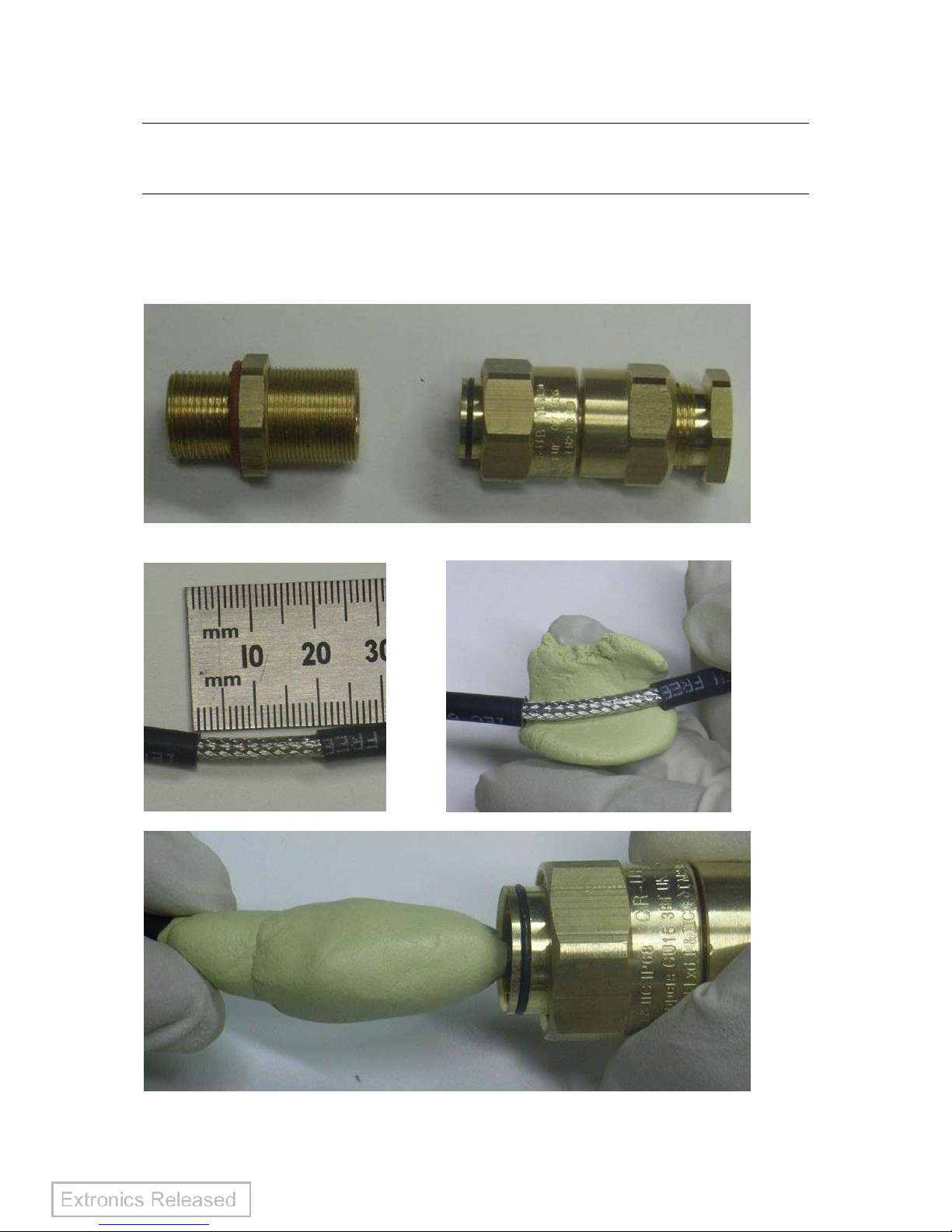
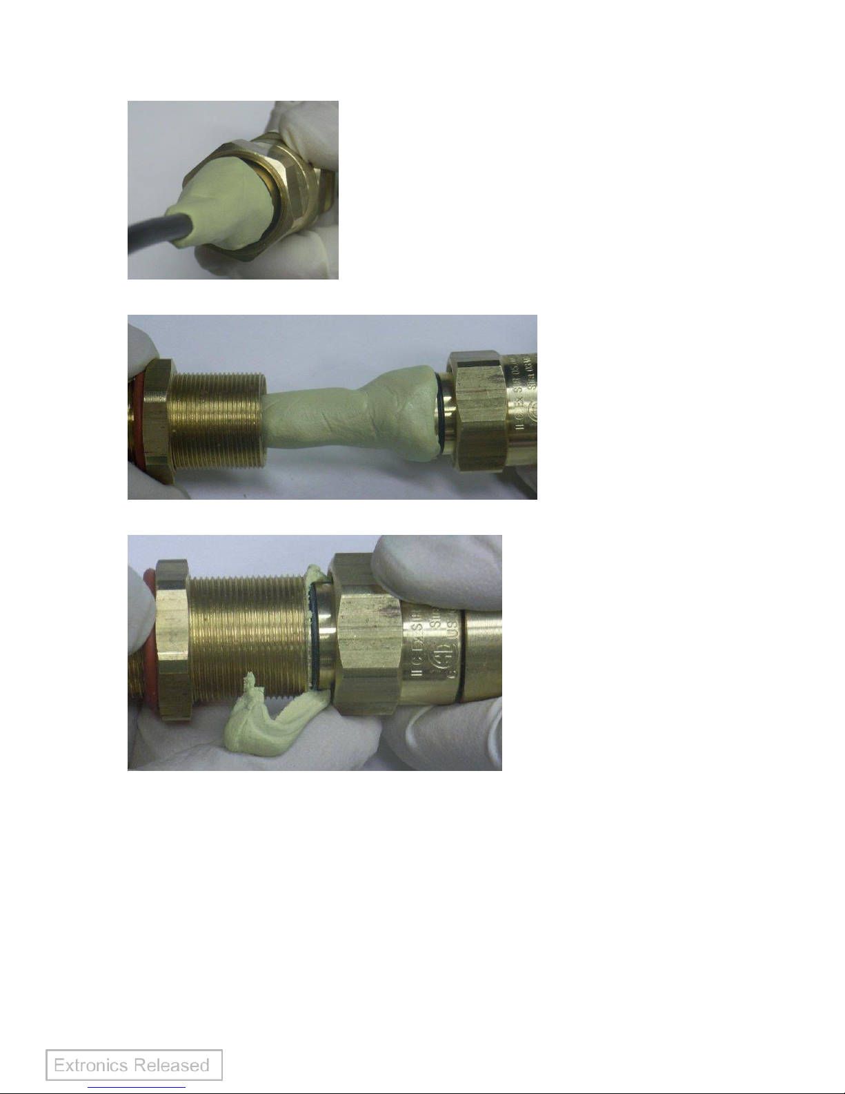
Figure 1
Figure 2 Figure 3
Figure 4
Operating Manual
20
Figure 5
Figure 6
Figure 7
Operating Manual
21
Figure 8
Figure 9

Operating Manual
22
1. Split gland as Shown in Figure 1
2. Fit Entry Body into the iWAP enclosure. Hand-tighten, then using wrench
tighten a further ½ turn. DO NOT EXCEED MAX TORQUE FOR
ENCLOSURE
3. Slide Rear Assembly (Back Nut, Mid Cap and Union Nut) onto cable.
CABLE PREPARATION
1. Cut around circumference of cable, being careful not to cut into braid.
2. Slide cable sheath to expose 20-25mm of braid as shown in figure 2.
3. Check compound has not passed its "Use By" date..Note Installation at
temperatures below 10C should be avoided.
4. Trim any hardened pieces from ends of stick. Mix the compound by
rolling, folding and breaking. Ease mixing by cutting large sticks in half.
Fully mixed compound has a uniform yellow colour with no streaks.
5. Support the cable and Rear Assembly, holding them roughly concentric.
Starting at the middle, pack a small amount of compound around the
screen of the cable as shown in figure 3. Pressing and working the
compound into the braid.
6. Pack Compound around the cable to completely fill the Rear Assembly
cup. Build up compound around the outside of the cores, with a slight
taper & to approximately 40mm in length, as shown in figure 4
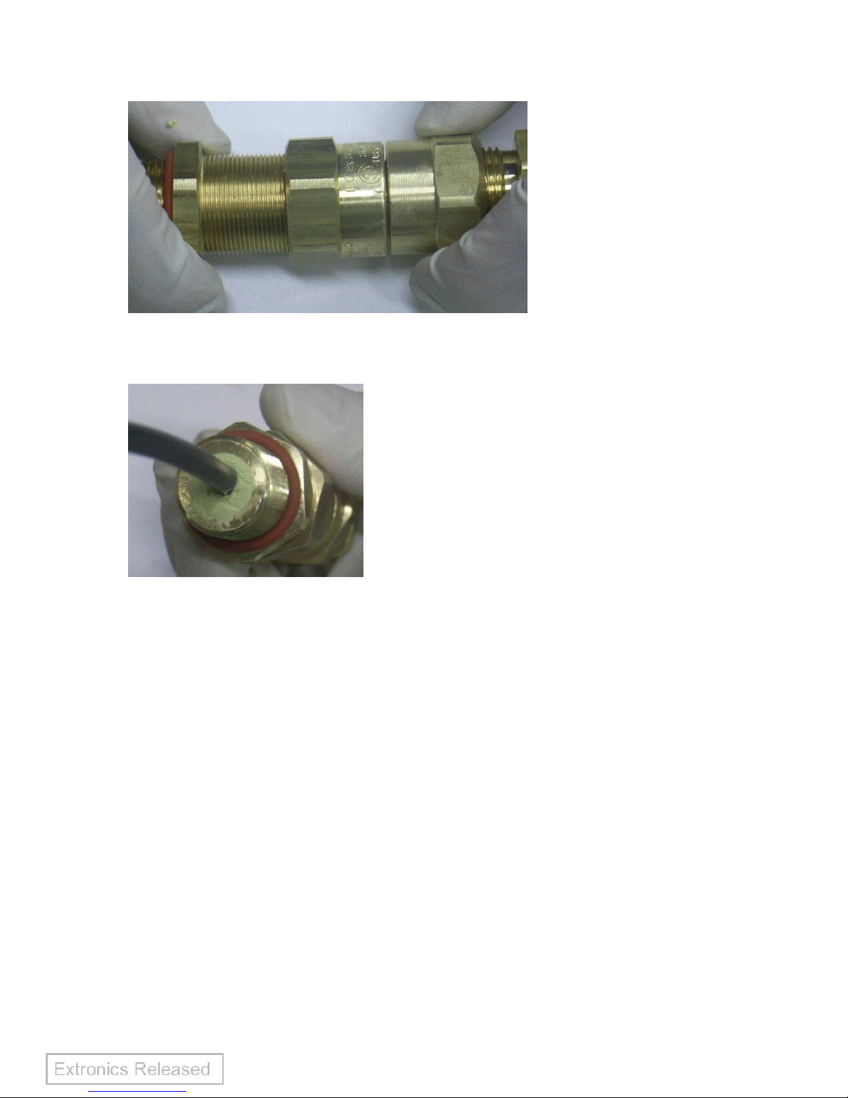
7. Pass the cable through and push compound into Entry Body until Rear
Assembly engages. Remove squeezed out compound as Screw Union
full turns onto Entry Body. Ensure that compound emerges at entry
thread, as per figures 7 and 8.
8. Clean off excess compound from Entry Body to allow withdrawal when
cured, as shown in figure 9.
9. Leave to cure for a minimum of 4 hours when working at 21ºC
10. To release and pull back joint for inspection, unscrew Union Nut
11. Hand-tighten Union Nut to remake joint. Then refer to table below and
tighten Union Nut using wrench to the given amount. Hold Mid Cap with
wrench and tighten Back Nut onto cable. Ensure seal makes full contact
with cable sheath, then tighten 1 extra turn
12. The equipment should not be energised until the compound has been
left to cure for at least 4 hours when working at 21ºC. See chart
‘Energising Time vs. Temperature’ for further guidance
HEALTH AND SAFETY WARNING
The resin used in the compound can cause eye and skin irritation. For your personal
protection, wear the gloves supplied while mixing and applying. The uncured
compound should not be allowed to come into contact with foodstuffs.
A COMPREHENSIVE SAFETY DATA SHEET PROVIDED BY THE COMPOUND
MANUFACTURER IS AVAILABLE ON REQUEST

Operating Manual
23
7 Type Codes
7.1 iANT100
iANT100 Zone 1 Omni Direc tio nal A nte nna iANT100-[#1]-[#2]-[#3]-[#4]-[#5]-[#6]-[#7]-[#8]
Spe cify opt ion [# 1] - Fre quency
2.4GHz F req uen cy 24
5 G Hz Frequenc y 58
GSM Quad -ba nd QB
Spe cify opt ion [# 2] - Cable Lengt h
5m 5
Spe cia l cab le len gth S
Spe cify opt ion [# 3] - Con ne cto r type
Str aight N- type male * 1
Rig ht angle N-type male ( Rec omm ended fo r use wi th Extronics iWAP 103) * 2
Str aight re ver se -polar ity SM A m ale 3
Rig ht-an gle re ver se -po lar ity TNC mal e 4
Str aight re ver se -polar ity BN C male 5
No con ne cto r f itt ed 6
* N .B. It is imp oss ibl e f or a st rai ght or ri ght -an gle d N- typ e c onn ect or f itt ed to t he cab le to pas s th rou gh the enclos ure en try for an M20
cab le gla nd. Eit her th e c onne cto r m ust be fit ted aft er pas sin g t he c abl e t hro ugh the en clo sur e h ole, or a lar ger M 25 enc los ure
ent ry sho uld be use d w ith a s uit abl e th rea d r edu cer . Th is per mit s th e N -type co nne ctor t o pa ss thr ough th e h ole .
Sel ect ei the r op tio n # 4 ( N) or o pti on# 7 (2 ).
Not e t hat the Ex tro nic s iW AP1 03 is sup plie d w ith M2 5 c able en tri es and M25 -M20 thr ead re duc ers as sta ndar d.
Spe cify opt ion [# 4] - Con ne cto r f itt ing
Selected conne cto r f itted F
Crimp conne cto r supplied separa tely for cu sto mer fitting (R G58 cr imp tool re quired) N
Spe cify opt ion [# 5] - Cable Gl and
No gla nd fitte d 1
Fit ted w ith CR-UB-NP-16- M20 Ex d cable gl and 2
Fit ted w ith CR-UB-NP-16- 075-NPT Ex d c able gland 3
Fit ted w ith cu sto mer-s upplie d cab le gla nd 4
Spe cify opt ion [# 6] - Cable Gl and Po sition
Cable gland in sta lle d at default d ist an ce fro m a ntenna (ca ble le ngt h m inu s 0 .45 m) D
Spe cia l cab le gla nd posit ion , s pec ify on orde r S
(Ca ble gl and mus t b e a min imu m o f 0 .65m fr om t he ant enn a, and a m ini mum
of 0. 45m is rec omm ende d b etw een th e gl and an d c onne cto r)
Spe cify opt ion [# 7] - Gland threa d r educe r s upp lie d
No thr ead redu cer su pplied 1
CR-UB-NP- 16-M2 0 E x d cable g lan d s up plied wit h M25 - M20 thre ad red uce r 2
Spe cify opt ion [# 8] - Mou nting br acket
Suppli ed with sta ndard al umi niu m w all mo un tin g bracket 1
Supplie d wit h 3 16 stain les s s tee l w all mo un tin g bra cket 2
Optional Ac cessories also av ail able separa tel y
316 stainle ss ste el wall mou nting bracket iA NTMB0 3

Operating Manual
24
7.2 iANT101
iANT101 Zone 1 Omni Direc tio nal A nte nna iANT101-[#1]-[#2]-[#3]-[#4]-[#5]-[#6] [#7]-[#8]
Spe cify opt ion [# 1] – Fre quency
2.4GHz 24
5 G Hz 58
437MH z 43
458.5MHz 45
466MH z 46
Spe cify opt ion [# 2] - Cable Lengt h
5m 5
10m 10
15m 15
20m 20
25m 25
Spe cia l cab le len gth S
Spe cify opt ion [# 3] - Con ne cto r type
Str aight N- type male * 1
Rig ht An gle N-type mal e (re com men ded fo r u se wi th E xtr oni cs iWAP10 3) ** 2
Str aight re ver se -polar ity SM A m ale 3
Str aight re ver se -polar ity TN C male 4
No con ne cto r f itt ed 5
* N .B. It is imp oss ibl e f or a st rai ght N- typ e c onne cto r f itt ed t o t he cab le t o pass th roug h t he enc losu re ent ry for an M20
cab le gla nd. Eit her th e c onne cto r m ust be fi tte d af ter pa ssin g the cab le thr ough th e e ncl osur e h ole , o r a la rger M2 5 en cl osur e
ent ry sho uld be use d w ith a s uit abl e th rea d r edu cer . Th is per mit s th e N -type co nne ctor t o pa ss thr ough th e h ole .
Sel ect ei the r op tio n # 4 ( N) or o pti on# 7 (2 ).
Not e t hat the Ex tro nic s i WAP1 03 is sup pli ed w ith M2 5 c able en tri es and M25 -M20 thr ead red uce rs as stan dar d.
**N .B. It is imp oss ibl e f or a ri ght -an gle N- typ e c onne cto r f itt ed t o t he cab le t o pass th roug h t he encl osure ent ry f or an M20
or M25 cab le gla nd. Th e c onne cto r m ust be fit ted af ter pa ssin g t he cab le t hr ough th e en cl osur e h ole , o r a lar ger en try use d.
Spe cify opt ion [# 4] - Con ne cto r f itt ing
Selected conne cto r f itted F
Selected conne cto r s upplie d sep ara tely for cu stomer f itt ing ( LMR -400 Crim p tool r equ ire d) N
Spe cify opt ion [# 5] - Cable Gl and
No gla nd fitte d 1
Fit ted w ith CR-UB-NP-20- M20 Ex d cable gl and 2
Fit ted w ith cu sto mer-s upplie d cab le gla nd 3
Spe cify opt ion [# 6] - Cable Gl and Po sition
Cable gland in sta lle d at defau lt dis tance from ant enn a (ca ble le ngt h m inu s 0 .45 m) D
Spe cia l cab le gla nd posit ion , s pec ify on orde r S
(Ca ble gl and mus t b e a min imu m o f 0 .65m fr om t he ant enn a, and a m ini mum
of 0. 45m is rec omm ende d b etw een th e gl and an d c onne cto r)
Spe cify opt ion [#7] - Gla nd threa d r educe r s upp lie d
No thr ead redu cer su pplied 1
CR-UB-NP- 16-M2 0 E x d cable g lan d s up plied wit h M25 - M20 thre ad red uce r 2
Spe cify opt ion [# 8] - Mou nting br acket
Suppli ed with galvan ised ste el 38mm pipe m oun ting br ack et 1
Suppli ed with 316 L stainl ess wa ll mou nting br acket 2
Optional Ac cessories also av ail able separa tel y
316L sta inless steel wall mount ing bracket iANTMB0 1
Operating Manual
25
8 EC Declaration of Conformity

Operating Manual
26

Operating Manual
27
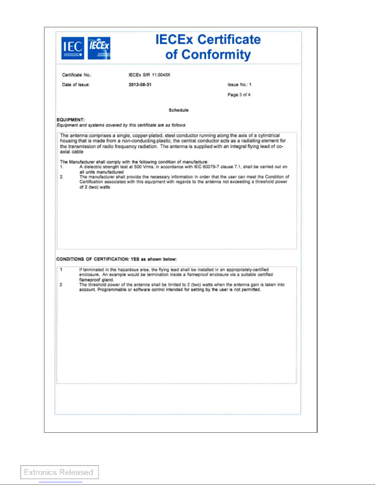
9 ATEX & IECEx CERTIFICATION

Operating Manual
28

Operating Manual
29

Operating Manual
30

Operating Manual
31
Operating Manual
32
Operating Manual
33

Operating Manual
34
10 Warranty Information
The Customer shall carry out a thorough inspection of the delivered project or
equipment with 21 days of delivery and shall give immediate written notification to the
Company of any omissions, defects or faults.
The Company warrants that the project or equipment delivered shall accord with the
Quotation or Pricing Schedule and related Company specifications, but it does not
warrant its fitness for any other purpose.
Extronics will make good, by repair or at Extronics option by the supply of a
replacement, defects which, under proper use in accordance with specifications and
manufacturer’s instructions, appear in the goods within a period of twelve calendar
months after the goods have been delivered and arise solely from faulty design,
materials or workmanship, provided always that defective parts have been returned
to Extronics if Extronics shall have so required.
The warranty of any goods is based upon a return to Extronics factory (Return to
Base Warranty) which will be at the Customers cost. The repaired or new parts will
be delivered by Extronics carriage paid. If you allege that goods are totally unfit for
their purpose they must be returned within 7 days of receipt. Site Warranty is
expressly excluded from these terms and conditions unless agreement is made in
writing between the parties it.
Extronics liability under this clause shall be in lieu of any warranty or condition
implied by law as to the quality or fitness for any particular purpose of the goods, and
save as provided in this clause Extronics shall not be under any liability, whether in
contract, or otherwise, in respect of defects in goods delivered or for any injury other
(than personal injury caused by Extronics negligence as defined in Section 1 of the
Unfair Contract Terms Act, 1977), damage or loss resulting from such defects or from
any work done in connection therewith, provided however that nothing in this clause
shall operate to exclude any warranty or condition implied by law as to the quality of
the goods in the event that the goods when sold by you or when sold by any person
or persons to whom you may sell the goods shall become the subject of a consumer
sale as defined in the Supply of Goods (Implied Terms) Act, 1973 except that any
claim under such warranty or condition shall have arisen from any act or omission by
you or by any person or persons selling the goods by way of a consumer sale.
 Loading...