

Introduction
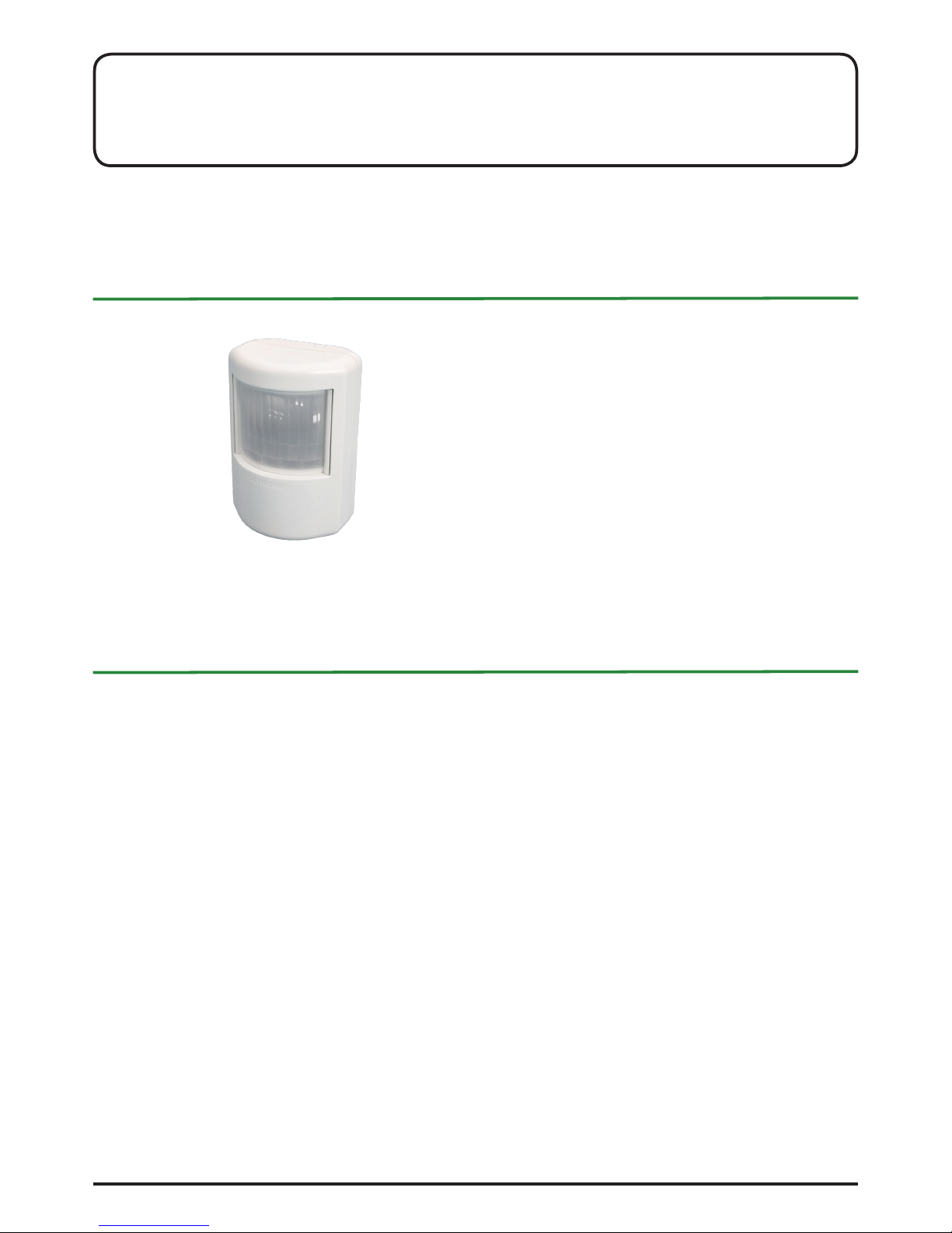
PD-33 DL is a passive infrared detector intended for presence
detection and the control of light ttings over a DALI bus. It uses
a pyroelectric sensor that reacts to changes in thermal radiation.
Properties
• PD-33 DL is able to turn on, dim and turn off DALI light ttings.
• It uses broadcast or group addressing.
• Multiple detectors work together if they are controlling the
same group of light ttings or if they are using broadcast
addressing.
• The light level can be controlled directly (100%, 10%, 0%)
or by choosing preset levels from scenes 10, 14 and 15.
• Adjustable presence delay of 2 seconds to 20 minutes.
• Timer controls duration of low-level lighting before switch-
off, 5 minutes or 30 minutes.
• Conguration for ofce environments that use a different
form of signal processing when presence is detected.
• “No start” mode can be selected that simply keeps lighting
switched on. (Switched on manually with pushbutton.)
• Power is supplied via the DALI bus (max. consumption 12
mA).
• Settings are adjusted using knobs and jumpers on the detector circuit board.
• Lens can be replaced to adjust the detection range. A
choice of lenses is available.
Commissioning
• Check that the “Activity Low/Ofce” jumper is set to the
“Low” position.
• Carry out a walk test over the entire detection area.
Note! The lens must be tted and the cover must be in
place. Adjust vertically and horizontally as required.
• After the walk test and adjustment, the presence delay
should be set to the lowest setting. In dynamic lighting control applications, such as stairways and corridors, a suitable
time is 1–2 minutes. In other applications, such as classrooms and garages, the time can be set to 6–8 minutes or
in line with the light source supplier’s recommendations.
• Set the “Occupancy Activity” jumper to match the level of
activity in the premises.
• We recommend that the LED is disconnected once adjustment is complete (see “Detector settings”), to minimise the
risk of tampering.
Basic terminology
• Broadcast: Broadcast addressing means that the detector
sends its DALI commands to all light ttings at the same time.
• Groups: The light ttings in a DALI system can also be controlled using group addresses. (DALI supports 16 groups.)
• Direct control: The light ttings are controlled by setting the
lighting level with DALI commands (Direct level).
• Scene: Each light tting can have 16 programmed scenes.
Each scene means that the light tting is lit at a certain level
(intensity). The light levels of the scenes for each light tting
can be programmed using a computer.
• Operating mode: Direct level or Extronic. Direct level means
that the light levels are controlled directly and at preset levels.
Extronic means that the light ttings are switched between
scenes 10, 14 and 15.
• Delays;
• Presence delay: The length of time that the lighting re-
mains switched on at the normal level after presence is no
longer detected.
Low-level delay: (Timer delay, base level duration) The
length of time that the lighting remains at the base level before it is switched off completely.
• No start: The lighting is not switched on automatically when
presence is detected. It can be switched on manually using
a pushbutton.
• Normal level: – light level that is used when someone is
present in the premises.
• Base level: – low light level that is used when premises are
empty.
Contents
Introduction ...........................................................................................1
Commissioning .....................................................................................1
Basic terminology .................................................................................1
Detector settings...................................................................................2
Mode Direct level: Direct control of light level.......................................3
Application example, “Mode Direct level” .............................................4
Mode Extronic: Control using scenes 10, 14 and 15 ............................5
Application example “Mode Extronic” ...................................................6
Wiring examples ...................................................................................9
Lens ....................................................................................................10
Replacing and adjusting lenses .........................................................10
Technical specication .......................................................................10
PRESENCE DETECTOR PD-33 DL v 1.1
Installation instructions
Order no. 13150, E no. 13 060 85
Extronic Elektronik AB +46 8 609 29 00
1
2015-12-14

Jumper “LED ind”/“No start” (LED)
Position “On”: The LED ashes when movement is
detected.
Position “Off”: The LED does not show when movement is
detected.
Without jumper: “No start” is a feature that prevents the
detector from switching on the lighting
automatically.
The LED can be disconnected once adjustment is complete, to
reduce the risk of tampering.
“Occupancy Activity” jumper / 5- or 30-minute
low-level delay
• “High”: For use in premises where people are only present
briey, e.g. corridors and underpasses, i.e. clearly dened
passageways. Gives ve minutes of base-level lighting.
• “Low/Ofce”: For use in premises where people sit for
long periods of time, e.g. in ofces, some warehouse
premises and libraries. The sensitivity increases when the
detector has previously detected no presence. Gives ve
minutes of base-level lighting.
• Without jumper: Gives 30 minutes of base-level lighting.
Signals are handled in the same way as for “Low/Ofce”.
“Mode” jumper
Extronic: Control using scenes
• Uses scene 10 while presence is detected.
• Uses scene 14 during low-level delay.
• Uses scene 15 when no-one is present.
Direct level: Turns on, dims and turns off lighting by direct
control.
• When presence is detected the lighting level is immediate-
ly switched to 100%.
• When presence is no longer detected the light level is im-
mediately switched to 10% during the low-level delay.
• After the low-level delay (5 or 30 minutes) the lighting is
switched off completely.
Without jumper: Provides special features in combination
with the “Selection number” mode selector.
”Selection number”:
0: Broadcast 1.5% base-level during low-level delay.
1-5: Groups 1 to 5 get 1.5% lighting level during low-level
delay.
F: Used with level selectors NP-2T DL and NP- 3T DL.
6 - E: Not used.
Mode selector (Selection number) 0–9 A–F
Choice of control by broadcast or groups 1 to 15.
Selection number determines which group is used.
• Selection number 0 is used for Broadcast.
• Selection numbers 1 to 9 send DALI commands to the re-
spective group.
• Selection numbers A–F give groups 10, 11, 12, 13, 14 and
15 respectively.
• Group 16 cannot be accessed.
NOTE! If NP-2T DL or NP-3T DL level switches are used,
the mode selector should be set to F and the “Mode” jumper
should be removed.
EXTRONIC
H
E
R
S
P
A
I
N
P
I
H
E
R
S
P
A
I
N
0
1
2
3
4
5
6
7
8
9
A
B
C
D
E
F
Selection
number
Mode
Group
Extronic
DA-1
(Group 0=Broadcast)
(no jumper see manual)
Min
Max
Sens.
Time
2s
2,5m
5m
10m
20m
LED Ind.
On
Off
Occupancy
Activity
R30CD
High
Low/Office
PD-33DL
v 1.0
DA-2
DALI
Further, to light
fittings or other
DALI equipment
Occupancy
Activity
jumper
Mode
jumper
Selection
number
Function selector
LED Ind.
LED indication
Detector settings
Opening the enclosure
The enclosure is opened by
twisting with a screwdriver
at the centre top or centre
bottom.
Potentiometers
Time (red): delay between time when presence was last detected until time when lighting is dimmed. Adjustable from 2 seconds to 20 minutes.
Sensitivity (yellow): this potentiometer is used to adjust sensitivity.
DALI terminals
PD-33 DL is only connected to the DALI bus and is intended for
detecting presence in lighting control systems. It has dual terminal blocks (DA-1 and DA-2) that can be used to connect the incoming and outgoing buses.
The DALI terminals are polarity independent. DA-1 and DA-2
are wired in pairs.
The detector is powered by the DALI bus.
Extronic Elektronik AB +46 8 609 29 00
2
2015-12-14
The lighting is switched
to 100%.
The lighting is switched
off with a pushbutton that sends
the DALI command “off”.
The lighting remains off as
long as presence is detect-
ed in the premises.
After a short period of absence
the detector returns to normal operation. (The time is set using the
red timer knob).
The lighting is
switched immediately to 100%.
The lighting is switched
immediately to 100%.
As long as presence is detected
the lighting level stays at 100%.
The presence delay can be set at
up to 20 minutes.
The light level stays at
100% until the presence
delay has elapsed.
The lighting is dimmed
gradually down to 10% (1.5%,
see text). The detector maintains the base level for 5 minutes (30 minutes, see text).
The lighting is
switched off completely.
Mode Direct level: Direct control of light level
Group mode sets the lighting level directly. The light ttings do
not need to be programmed if Broadcast is used. If group addressing (groups 1–15) is used, it is only necessary to program
the light ttings with their group designations.
When presence is detected, the light level is set at 100%.
The presence delay can be set at up to 20 minutes.
When presence is no longer detected and the presence delay
has elapsed, the lighting is gradually dimmed to 10% and stays
at this level for 5 minutes. The detector then switches the light
level to 0%.
• Several detectors can work together if they belong to the
same group or are in Broadcast mode.
• To prevent the lighting from being switched on automatically (“No start”), remove the “LED indication” jumper.
• The lighting can be switched off using one or more pushbuttons that send the DALI command “off”.
• The lighting can be switched on using one or more pushbuttons that send the DALI command “recall max level”.
• A 30-minute low-level delay can be selected by removing
the “Occupancy Activity” jumper (normally 5 minutes).
• The lighting can be dimmed to 1.5% instead of 10% by re-
moving the “Mode” jumper. This only applies in Broadcast
mode (0) or for groups 1 to 5.
• Multiple detectors assigned to different groups work independently of each other.
Automatic switching on, dimming and switching off
Entry 100% Presence 100% Exit 100% Base level 10% No presence
Manual control “off”
Presence 100% Manual control off Presence off No presence off New entry 100%
Entry 0% Manual control
on 100%
Presence 100% Exit 100% Base level 10% New entry
100 %
The lighting is not
switched on.
The lighting is switched
on using a pushbutton
that sends the DALI
command “recall max
level”.
As long as presence
is detected the lighting
remains at 100%.
The presence delay
can be set at up to 20
minutes.
The light level stays
at 100% until the
presence delay has
elapsed.
The lighting is dimmed
gradually down to 10%
(1.5%, see text). The
detector maintains the
base level for 5 minutes (30 minutes, see
text).
If someone enters
the premises be
fore the lighting is
switched off, the
light level is raised
to 100% again.
Manual control “No start”
Extronic Elektronik AB +46 8 609 29 00
3
2015-12-14

G2. Several small rooms with automatic control
The detectors each control their own room, independent of the
other detectors in the DALI loop. The light ttings must be given
the same group designation as the PD-33 DL detectors. In this
example, group 1 and group 2.
• When presence is detected, the light ttings are switched
on at the normal level of 100%.
• After the presence delay, the lighting is dimmed to 10% for
5 minutes (low-level delay).
• If no movement is detected during the low-level delay (5
minutes) the lighting is switched off completely.
230 VAC
Mode: Direct level
Selection number: 1
123456789 10 11 12 13
14 15 16 17 18 19 20 21 22 23 24 25
DALI-driver
Input supply:......................................... 230 VAC
Output supply (detector):...................... DA+ /DA-
Mode: Direct level
Selection number: 2
1
2
Comments
• If several detectors are connected in parallel they will help
to control the area.
• The lighting can be dimmed to a base level of 1.5% instead of 10% by removing the “Mode” jumper.
• The low-level delay time can be set to 30 minutes instead
of 5 minutes by removing the “Occupancy Activity” jumper.
• If light levels other than 100%, 10%, 1.5% and 0% are required, the light ttings must be controlled using scenes.
Application example, “Mode Direct level”
G1. Simple example of controlling a DALI loop with
PD-33 DL
No programming of light ttings is needed
Broadcast to all light ttings, with direct control of all light ttings
in the loop, and without any need for programming detectors or
light ttings.
• When presence is detected, the light ttings are switched
on at the normal level of 100%.
• After the presence delay, the lighting is dimmed to 10% for
5 minutes (low-level delay).
• If no movement is detected during the low-level delay (5
minutes) the lighting is switched off completely.
Comments
• If several detectors are connected in parallel they will help
to control the area.
• A base level of 1.5% can be chosen instead of 10% (see
section on “Jumper Mode”).
• A low-level delay of 30 minutes can be chosen instead of
5 minutes (see section on “Occupancy Activity”).
EXTRONIC
H
E
R
S
P
A
I
N
P
I
H
E
R
S
P
A
I
N
0
1
2
3
4
5
6
7
8
9
A
B
C
D
E
F
Selection
number
Mode
Direct level
Extronic
DA-1
(Group 0=Broadcast)
(no jumper see manual)
Min
Max
Sens.
Time
2s
2,5m
5m
10m
20m
LED Ind.
On
Off
Occupancy
Activity
R30CD
High
Low/Office
PD-33DL
v 1.1
DA-2
(30min, Low/Office)
(No start)
123456789 10 11 12 13
14 15 16 17 18 19 20 21 22 23 24 25
DALI-driver
Input supply:......................................... 230 VAC
Output supply (detector):...................... DA+ /DA-
PD-33 DL
"Mode" = Direct level
"Selection number" = 0 (Broadcast)
Extronic Elektronik AB +46 8 609 29 00
4
2015-12-14

The lighting is not
switched on.
The lighting is switched on
using a pushbutton that
sends the DALI command
“go to scene 10”.
As long as presence is de-
tected the lighting stays on
at scene 10. The presence
delay can be set at up to
20 min.
During the presence
delay scene 10 is active.
The lighting is gradually
dimmed to scene 14. The
detector maintains scene
14 for 5 min. (30 min., see
text).
If someone enters
the premises before
scene 15 is activated
the lighting is switched
back to scene 10.
Mode Extronic: Control using scenes 10, 14
and 15
Extronic mode sets the lighting level using scenes 10, 14 and
15, with the command “Go to scene 10, 14 or 15”. The light ttings must be programmed to set the lighting level for scenes
10, 14 and 15.
If Broadcast is used, there is no need to program the light ttings
with group designations. If group addressing (groups 1–15) is
used, the light ttings must be programmed with group designations.
When presence is detected the lighting is switched to scene 10.
(Recommended as 80–100% light level). The presence delay
can be set at up to 20 minutes after presence was last detected.
The lighting is then dimmed gradually down to scene 14 (e.g.
1% or 10% base lighting). The detector remains at scene 14 for
5 minutes (low-level delay) if no presence is detected.
The detector then switches to scene 15. (e.g. 1% or 10%)
• Several detectors can work together if they belong to the
same group, or are in Broadcast mode.
• To prevent the lighting from being switched on automatically (“No start”), remove the “LED indication” jumper.
• The lighting can be switched off using one or more pushbuttons that send the DALI command “off”.
• The lighting can be switched on using one or more pushbuttons that send the DALI command “go to scene 1–5 or 10”.
• A 30-minute low-level delay can be obtained if the “Occupancy activity” jumper is removed (normally 5 minutes).
• Manual scenes can be created using scenes 1–5, to provide lighting for cleaning or showing lms, for example.
• Detectors assigned to different groups work independently
of each other.
Manual control “off”
Manual control “No start”
Using scenes 1 to 5 manually
Presence scene 10 Manual control
scene 1
Presence scene 1 Exit scene 1 Base level scene 14 New entry
scene 10
Lighting is switched to
scene 10.
As long as presence is de-
tected the lighting remains
at scene 10. The presence
delay can be set at up to 20
minutes.
The lighting remains at
scene 10 until the presence delay has elapsed.
The lighting is gradually
dimmed to scene 14. The
detector maintains scene
14 for 5 minutes (30 minutes, see text).
The lighting is switched
to scene 15. To prevent a
few light ttings from being
switched off completely they
can be programmed for 10%
lighting, for example.
Presence scene 10 Manual control off Presence off No presence off Entry scene 10
Lighting is switched on at
scene 10.
The lighting is switched off
with a pushbutton that sends
the DALI command “off”.
The lighting remains off
as long as presence is
detected in the
premises.
After the preset presence delay
the detector returns to normal operation. (The delay is set using the
red timer knob).
The lighting is
switched back to
scene 10.
Entry scene 15 Manual control
scene 10
Presence scene 10 Exit
scene 10
Base level
scene 14
New entry
scene 10
Lighting is switched
on at scene 10.
The lighting is switched on
using a pushbutton
that sends the DALI command “go to scene 1”.
As long as presence
is detected the
lighting stays on
at scene 1.
During the presence
delay, scene 1 is active.
The lighting is gradually
dimmed to scene 14.
If someone
enters, scene
10 is activated
again.
Extronic Elektronik AB +46 8 609 29 00
5
2015-12-14

Always lit at
the door.
Scene 10 = 100 %
Scene 14 = 10 %
Scene 15 = 10 %
Main lighting when
scene 15
is activated.
Scene 10 = 100 %
Scene 14 = 10 %
Scene 15 = 0 %
1 2
3
4
5
Same area
230 VAC
1 2 3 4 5 6 7 8 9 10 1112 13
14
1516 17
18
19 20 21 22
232425
Input supply:......................................... 230 VAC
Output supply (detector):...................... DA+ /DA-
DALI-driver
Mode:
Extronic
0 (Broadcast)
Selection number:
Mode:
Extronic
0 (Broadcast)
Selection number:
Mode:
Extronic
0 (Broadcast)
Selection number:
Mode:
Extronic
0 (Broadcast)
Selection number:
Mode:
Extronic
0 (Broadcast)
Selection number:
Application example “Mode Extronic”
E1 – Garage with some light ttings that are never
switched off
Setting
‟Mode - Extronic”
The detectors jointly control the whole garage using scenes
10, 14 and 15. The light ttings near the entrances should never be switched of completely.
All light ttings must be programmed with scenes 10, 14 and
15.
Extronic Elektronik AB +46 8 609 29 00
6
2015-12-14

Pushbutton
Pushbutton
E2 – Corridor where the light level can be increased
using pushbutton(s)
‟Mode - Extronic”
Normally the premises are controlled automatically using
scenes 10, 14 and 15. The light ttings are programmed for an
automatic normal light level (scene 10) of 50%. In this example
it is required to increase the light level to 100%. This is done using scene 1. The lighting is switched to 100% by one or more
pushbuttons that send the DALI command “go to scene 1”.
The low-level delay time is increased from 5 minutes to 30 minutes by removing the “Occupancy Activity” jumper.
In this case the light ttings are programmed to:
Scene 10 = Max. light level when presence is detected
(normal level).
Scene 14 = Low level, no presence detected, 5% (base level)
Scene 15 = 0%.
Scene 1 = 100% (cleaning lighting), manual level that is
switched on with pushbutton.
230 VAC
Mode: Extronic
Selection number: 0
1 2 3 4 5 6 7 8 9 10 11 1213
14
15 1617
18
19 20 21 22
2324 25
Input supply:......................................... 230 VAC
Output supply (detector):...................... DA+ /DA-
DALI-driver
Pushbutton
Go to scene 1
Mode: Extronic
Selection number: 0
Pushbutton
Go to scene 1
Extronic Elektronik AB +46 8 609 29 00
7
2015-12-14

E3 – Classroom where lighting levels can be changed
using pushbuttons
‟Mode - Extronic”
Normally the premises are controlled automatically using
scenes 10, 14 and 15, and there are also the following manual functions:
• Board lighting can be switched on manually with a pushbutton.
• Projector mode, ceiling lighting is reduced to 1% by press-
ing a pushbutton.
• Main lighting is switched back to normal level with one or
more pushbuttons.
“Mode” jumper is set to Extronic.
The low-level delay time is increased from 5 minutes to 30 minutes (base level).
(This can be increased to 30 minutes by removing the “Occupancy Activity” jumper.)
Comments
To prevent the lighting from being switched on automatically
when presence is detected, activate the “No start” function. This
is done by removing the “LED indication” jumper. One or more
pushbuttons will then be required to switch the lighting on, by
activating scene 3.
In this example the scenes are used as follows:
Scene 1: Manual board lighting and main lighting.
Scene 2: Manual projector mode.
Scene 3: Main lighting is switched on manually (normal level).
Scene 10: Automatic level.
Scene 14: Low-level delay of 5 minutes at base level.
Scene 15: Switched off, 0% lighting when no-one is present.
Main lighting
Board lighting
Pushbutton
scene 1 (main lighting and board lighting)
Pushbutton
scene 3 (main lighting)
Pushbutton
scene 3
Pushbutton
off
Pushbutton
scene 2 (prjector mode)
The board lighting is programmed as follows:
Scene 1: 0% (manual board lighting and main lighting).
Scene 2: 0% (manual projector mode).
Scene 3: 100% main lighting is switched on manually.
Scene 10: 0% automatic level.
Scene 14: 0% low-level delay of 5 minutes at base level.
Scene 15: 0% lighting when no-one is present.
In this case the ceiling ttings are programmed as follows:
Scene 1: 100 % (manual board lighting and main lighting).
Scene 2: 1% (manual projector mode).
Scene 3: 100% main lighting is switched on manually.
Scene 10: 100% automatic level.
Scene 14: 10% low-level delay of 5 minutes at base level.
Scene 15: 0% lighting when no-one is present.
Extronic Elektronik AB +46 8 609 29 00
8
2015-12-14

PD-33
NP-2T
EXTRONIC
H
E
R
S
P
A
I
N
P
I
H
E
R
S
P
A
I
N
0
1
2
3
4
5
6
7
8
9
A
B
C
D
E
F
Selection
number
Mode
Group
Extronic
DA-1
(Group0=Broadcast)
(nojumpersee manual)
Min
Max
Sens.
Time
2s
2,5m
5m
10m
20m
LEDInd.
On
Off
Occupancy
Activity
R30CD
High
Low/Office
PD-33DL
v1.0
DA-2
12345678910111213
141516171819202122232425
Level switch NP-2T DL
Bus powersupply and bus controller
for digitallydimmable luminaires.
Timer forswitching off the light.
Extronic• Stockholm • Sweden
Inputsupply:......................................... 100 -240 VAC
Outputsupply (detector):...................... 12VDC, 200 mA
Outputsupply digital communication:...21 V, 200mA
Timer:.....................................................0 - 120minutes
Light
Sensor
100%
100h
100%
100h
Switch
Timer
15m
30m
1h
2h
0
DA+DA-
C-NO-NC
+12VDC-
19-20
L-N
230VAC
+15-16
Light
22-23-24
Relay
Light
Sensivity
High
Level
NP-2T DL
Low
Level
4-56-78-910-11
Slow
Fast
+minutes
Add
Det.Time
SoftDim
0
2,5
5
10
20
Det
DL
DL
L3
L2
L1
N
N
L1
DA+DA-
Wiring examples
Presence detector PD-33 DL with NP-2T DL in premises
equipped with DALI light ttings.
The DALI bus is powered by an Extronic level switch, NP-2T
DL.
The lighting levels when people are present and during low level
are set by the level switch.
One or more PD-33 DL detectors signal presence and lack of
presence to the level switch. When presence is detected, the
detector LED on the level switch ashes. The detector’s presence delay can be increased using an extra presence delay
knob in the level switch.
The lighting can be switched on or off and dimmed manually using a pushbutton connected to the level switch NP-2T DL.
When PD-33 DL is used with NP-2T DL the mode jumper should
be removed and the selector knob set to “F”.
PD-33
EXTRONIC
H
E
R
S
P
A
I
N
P
I
H
E
R
S
P
A
I
N
0
1
2
3
4
5
6
7
8
9
A
B
C
D
E
F
Selection
number
Mode
Group
Extronic
DA-1
(Group0=Broadcast)
(nojumpersee manual)
Min
Max
Sens.
Time
2s
2,5m
5m
10m
20m
LEDInd.
On
Off
Occupancy
Activity
R30CD
High
Low/Office
PD-33DL
v1.0
DA-2
DL
L3
L2
L1
N
15
16
4
5
19 20
Inputsupply...........................................
Outputsupply...............................................12V,200mA
Digitalout....................................................Max.200mA
Timer........................................................0-120minutes
ExtronicAB•Stockholm•Sweden
LevelswitchNP-3TDL
....100-240VAC
Buspowersupplyandbuscontroller
fordigitallydimmableluminaires.
Timerforswitchingofthelight.
12345678910111213
141516171819202122232425
Timer
15m
30m
1h
2h
0
100%
100h
100%
100h
0
2,5
5
10
20
Slow
Fast
StartBlock
Min
Max
LowLevel
Light
Sensor
SwitchDet
Off
Min
Max
4-5
6-78-9
10-11
+15-16
19-20
22-23-24
Min
Reg
Max
DA+DA-
Light
L-N
C-NO-NC
Relay
NP-3TDL
Luxat Max
Luxat Min
Off
+12VDC-
+minutes
Add
Det.Time
SoftDim
230VAC
Max
PowerLevel
Min
PowerLevel
With level switch NP-2T DL
With level switch NP-3T DL and daylight control
NP-3T DL adjusts the lighting output to compensate for the
amount of sunlight entering the premises.
Premises with DALI light ttings.
The DALI bus is powered by an Extronic level switch, NP-3T
DL. The lighting levels when people are present and during low
level are set by the level switch.
One or more PD-33 DL detectors signal presence and lack of
presence to the level switch. When presence is detected, the
detector LED on the level switch ashes. The detector’s presence delay can be increased using an extra presence delay
knob in the level switch.
The lighting can be switched on or off and dimmed manually
using a pushbutton connected to the level switch NP-3T DL.
When PD-33 DL is used with NP-3T DL the mode jumper
should be removed and the selector knob set to “F”.
0
1
2
3
4
5
6
7
8
9
A
B
C
D
E
F
Selection
number
Mode
Direct level
Extronic
(Group 0=Broadcast)
(no jumper see manual)
Min
Max
Sens.
Time
2s
2,5m
5m
H
E
R
S
P
A
I
N
10m
20m
P
I
H
E
R
S
P
A
I
N
Jumper "Mode"
removed
"Selection
number" = F
0
1
2
3
4
5
6
7
8
9
A
B
C
D
E
F
Selection
number
Mode
Direct level
Extronic
(Group 0=Broadcast)
(no jumper see manual)
Min
Max
Sens.
Time
2s
2,5m
5m
H
E
R
S
P
A
I
N
10m
20m
P
I
H
E
R
S
P
A
I
N
Jumper "Mode"
removed
"Selection
number" = F
Setting up PD-33 DL
Setting up PD-33 DL
Extronic Elektronik AB +46 8 609 29 00
9
2015-12-14

Lens
Standard lens no. 15 covers a range of 40 metres and an angle of 90°, and is suitable for most premises. A choice of optional lenses is available. When someone walks straight across the
eld it generates a strong signal in the sensor element. When
someone moves in line with the eld (towards or away from
the detector) it generates a much weaker signal. The detector
should therefore normally be placed so that people pass straight
across (at 90° to) the eld produced by the lens. The ideal
placement is almost always to install the detector in a corner.
NOTE! The detector will not work without a lens!
Choosing a lens
There are a number of different lenses for PD-33 DL that can
be used for different purposes. Long-range lenses, e.g. for corridors up to 80 m long (lens 34 or 47). Lenses with many tightly
packed detection elds, e.g. for classrooms (lens 51).
PD-33 DL is supplied as standard with lens number 15. This
has 58 detection elds that cover three levels. It has a range of
40 m and is suitable for installation in a corner.
The detector should be mounted at a suitable height and aimed
at the part of the body that radiates most energy (the torso). A
suitable installation height is often 1.9–2.2 m.
Replacing and adjusting lenses
Replacing the lens
1. Release the lens clips
from inside the detector cover.
2. Remove the clips from the outside
and remove the old lens.
3. Fit the new lens with the
ridged side outwards. The lens number should
be at the top right
corner (seen from the front).
Adjusting the lens
The vertical angle is adjusted by moving the circuit board up or
down. The horizontal angle is adjusted by moving the lens to the
right or left.
Adjusting the vertical angle
The vertical angle of the detection eld is adjusted by moving
the circuit board up or down. The scale shows the angle between the upper eld of the lens and an imaginary horizontal
line. If the circuit board is moved upwards it lowers the detection
eld, and vice versa. The vertical adjustment of the circuit board
is preset at -5°. The recommended installation height for best
detection is 1.9–2.2 m.
Masking lens elements
Lens elements can be masked to limit the detection area.
Self-adhesive aluminium foil tape, like that used to protect windows, will block 100 per cent of thermal radiation.
Accessories
Level selector
NP-2T DL
• Controls DALI light ttings using
broadcast commands.
• No programming required.
• Built-in power supply for
DALI bus.
• Supply voltage 230 V AC.
• Add Detector Time. Allows detec-
tor delay time to be set in
addition to time set by detector.
NP-3T DL also offers:
• Comfort lighting control, which
combines daylight adjustment
via a light sensor, and fuzzy logic, which continuously adjusts the
lighting between two levels: “Lux
at Max” and “Lux at Min”. See al-
so the section on “Comfort lighting
control” in
the manual for NP-3T DL.
Protective grille
Used for installation in vulnerable
locations, such as sports halls. There
is also a model that can be used to install the detector at 45° in combination
with an angle plate on a wall.
Order no. 13038,
large; 13038A,
corner; 13039.
See also product catalogues.
Universal mountings
BR1, BR2, BR3 can be used where
normal placement (corner mounting) is
not suitable or possible.
Order no. 13085, -86, -87,
Lenses
See Extronic’s product catalogue or the website for information
on choosing a suitable lens.
Technical specication
Vertical adjustment: +10° to -20° calibrated scale.
Horizontal adjustment: Up to 30°.
Detection area with
standard lens 15:
Max. reach 40 m at 90°.
Voltage: Supplied by DALI bus.
Current: Max. 12 mA.
Start-up time: < 2 minutes.
LED: Red IR, can be disconnected.
Detector: Dual-element, low-noise pyroelectric IR detector.
Enclosure: IP42.
Dimensions (W X H X D): 70 x 102 x 50 mm.
Weight: 93 g.
Declaration of conformity with:
- EMC Directive 2004/108/EC
- RoHS Directive 2011/65/EC
When the level detector reaches the end of its useful life
it must be recycled at an approved recycling facility.
Extronic Elektronik AB +46 8 609 29 00
10
2015-12-14
 Loading...