

Page 1
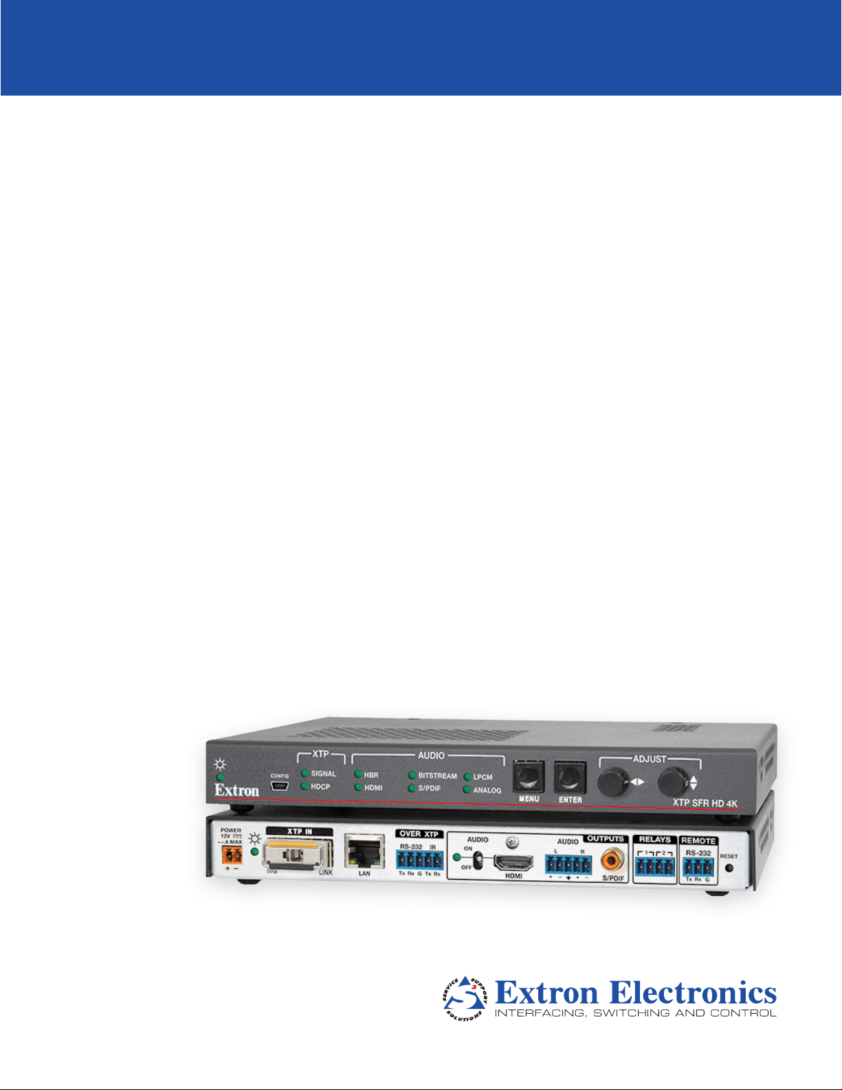
XTP SFR HD 4K
XTP Scaling Fiber Optic Receiver
User Guide
XTP Systems
68-2203-01 Rev. C
03 17
Page 2
Safety Instructions
Safety Instructions • English
WARNING: This symbol, , when used on the product, is intended to
alert the user of the presence of uninsulated dangerous voltage within the
product’s enclosure that may present a risk of electric shock.
ATTENTION: This symbol, , when used on the product, is intended
to alert the user of important operating and maintenance (servicing)
instructions in the literature provided with the equipment.
For information on safety guidelines, regulatory compliances, EMI/EMF
compatibility, accessibility, and related topics, see the Extron Safety and
Regulatory Compliance Guide, part number 68-290-01, on the Extron website,
www.extron.com.
Sicherheitsanweisungen • Deutsch
WARNUNG: Dieses Symbol auf dem Produkt soll den Benutzer darauf
aufmerksam machen, dass im Inneren des Gehäuses dieses Produktes
gefährliche Spannungen herrschen, die nicht isoliert sind und die einen
elektrischen Schlag verursachen können.
VORSICHT: Dieses Symbol auf dem Produkt soll dem Benutzer in der
im Lieferumfang enthaltenen Dokumentation besonders wichtige Hinweise
zur Bedienung und Wartung (Instandhaltung) geben.
Weitere Informationen über die Sicherheitsrichtlinien, Produkthandhabung,
EMI/EMF-Kompatibilität, Zugänglichkeit und verwandte Themen finden Sie in
den Extron-Richtlinien für Sicherheit und Handhabung (Artikelnummer
68-290-01) auf der Extron-Website, www.extron.com.
Instrucciones de seguridad • Español
ADVERTENCIA: Este símbolo, , cuando se utiliza en el producto,
avisa al usuario de la presencia de voltaje peligroso sin aislar dentro del
producto, lo que puede representar un riesgo de descarga eléctrica.
ATENCIÓN: Este símbolo, , cuando se utiliza en el producto, avisa
al usuario de la presencia de importantes instrucciones de uso y
mantenimiento recogidas en la documentación proporcionada con el
equipo.
Para obtener información sobre directrices de seguridad, cumplimiento
de normativas, compatibilidad electromagnética, accesibilidad y temas
relacionados, consulte la Guía de cumplimiento de normativas y seguridad de
Extron, referencia 68-290-01, en el sitio Web de Extron, www.extron.com.
Instructions de sécurité • Français
AVERTISSEMENT : Ce pictogramme, , lorsqu’il est utilisé sur le
produit, signale à l’utilisateur la présence à l’intérieur du boîtier du produit
d’une tension électrique dangereuse susceptible de provoquer un choc
électrique.
ATTENTION : Ce pictogramme, , lorsqu’il est utilisé sur le produit, signale
à l’utilisateur des instructions d’utilisation ou de maintenance importantes
qui se trouvent dans la documentation fournie avec le matériel.
Pour en savoir plus sur les règles de sécurité, la conformité à la réglementation,
la compatibilité EMI/EMF, l’accessibilité, et autres sujets connexes, lisez les
informations de sécurité et de conformité Extron, réf. 68-290-01, sur le site
Extron, www.extron.com.
Istruzioni di sicurezza • Italiano
AVVISO: Questo simbolo, ,quando viene utilizzato il prodotto, serve ad
avvisare l’utente della presenza di tensioni pericolose non isolate all’interno
del prodotto, che può presentare un rischio di scosse elettriche.
ATTENTZIONE: Questo simbolo, , quando viene utilizzato il prodotto,
serve ad avvisare l’utente di importanti istruzioni di uso e manutenzione
(assistenza) nella letteratura fornita con l’apparecchiatura.
Per informazioni sulle linee guida di sicurezza, adempimenti normativi,
compatibilità EMI/EMF, accessibilità e argomenti correlati, vedere la sicurezza di
Extron e Regulatory Compliance Guide, parte numero 68-290-01, sul sito Web
Extron, www.extron.com.
Instrukcje bezpieczeństwa • Polska
OSTRZEŻENIE: Ten symbol, , gdy używany na produkt, ma na celu
poinformować użytkownika o obecności izolowanego i niebezpiecznego
napięcia wewnątrz obudowy produktu, który może stanowić zagrożenie
porażenia prądem elektrycznym.
UWAGI: Ten symbol, , gdy używany na produkt, jest przeznaczony do
ostrzegania użytkownika ważne operacyjne oraz instrukcje konserwacji
(obsługi) w literaturze, wyposażone w sprzęt.
Informacji na temat wytycznych w sprawie bezpieczeństwa, regulacji wzajemnej
zgodności, zgodność EMI/EMF, dostępności i Tematy pokrewne, zobacz Extron
bezpieczeństwa i regulacyjnego zgodności przewodnik, część numer
68-290-01, na stronie internetowej Extron, www.extron.com.
Инструкция по технике безопасности • Русский
ПРЕДУПРЕЖДЕНИЕ: Данный символ, , если указан
на продукте, предупреждает пользователя о наличии
неизолированного опасного напряжения внутри корпуса
продукта, которое может привести к поражению
электрическим током.
ВНИМАНИЕ: Данный символ, , если указан на продукте,
предупреждает пользователя о наличии важных инструкций
по эксплуатации и обслуживанию в руководстве,
прилагаемом к данному оборудованию.
Для получения информации о правилах техники безопасности,
соблюдении нормативных требований, электромагнитной
совместимости (ЭМП/ЭДС), возможности доступа и других
вопросах см. руководство по безопасности и соблюдению
нормативных требований Extron на сайте Extron: www.extron.com,
номер по каталогу - 68-290-01.
安全说明 • 简体中文
警告: 产品上的这个标志意在警告用户该产品机壳内有暴露的危险 电压,
有触电危险。
注意: 产品上的这个标志意在提示用户设备随附的用户手册中有
重要的操作和维护(维修)说明。
关于我们产品的安全指南、遵循的规范、EMI/EMF 的兼容性、无障碍
使用的特性等相关内容,敬请访问 Extron 网站 www.extron.com,参见
Extron 安全规范指南,产品编号 68-290-01。
Page 3
安全記事 • 繁體中文
警告: 若產品上使用此符號,是為了提醒使 用者,產品機殼內存在著
可能會導致觸電之風險的未絕緣危險電壓。
注意: 若產品上使用此符號,是為了提醒使用者,設備隨附的用戶手冊中有重
要的操作和維護(維修)説明。
有關安全性指導方針、法規遵守、EMI/EMF 相容性、存取範圍和相關主題的詳細資
訊,請瀏覽 Extron 網站:www.extron.com,然後參閱《Extron 安全性與法規
遵守手冊》,準則編號 68-290-01。
안전 지침 • 한국어
경고: 이 기호 가 제품에 사용될 경우, 제품의 인클로저 내에 있는
접지되지 않은 위험한 전류로 인해 사용자가 감전될 위험이 있음을
경고합니다.
주의: 이 기호 가 제품에 사용될 경우, 장비와 함께 제공된 책자에 나와
있는 주요 운영 및 유지보수(정비) 지침을 경고합니다.
안전 가이드라인, 규제 준수, EMI/EMF 호환성, 접근성, 그리고 관련 항목에
대한 자세한 내용은 Extron 웹 사이트(www.extron.com)의 Extron 안전 및
규제 준수 안내서, 68-290-01 조항을 참조하십시오.
安全上のご注意
警告: この記号 が製品 上に 表示されている場合 は、筐 体内に絶 縁されて
いない高電 圧が流れ、感電の危険があることを示しています。
注意:この記号 が製品上に表示されている場合は、本機の取扱説明書に
記載されている重要な操作と保守(整備)の指示についてユーザーの注
意を 喚 起 す る も ので す。
安全上のご注意、法規厳守、EMI/EMF適合性、その他の関連項目に
つ い て は 、エクストロンのウェブ サ イト www.extron.com よ り 『 Extron Safety
and Regulatory Compliance Guide』 (P/N 68-290-01) をご覧ください 。
• 日本語
Copyright
© 2017 Extron Electronics. All rights reserved.
Trademarks
All trademarks mentioned in this guide are the properties of their respective owners.
The following registered Trademarks (®), registered service Marks (SM), and Trademarks (™) are the property of RGBSystems, Inc. or
Extron Electronics (see the current list of trademarks on the Terms of Use page at www.extron.com):
Registered Trademarks
Extron, AVTrac, Cable Cubby, ControlScript, CrossPoint, DTP, eBUS, EDID Manager, EDID Minder, Flat Field, FlexOS, Global Configurator,
Global Scripter, GlobalViewer, Hideaway, Inline, IPIntercom, IPLink, KeyMinder, LinkLicense, LockIt, MediaLink, MediaPort, NetPA, PlenumVault,
PoleVault, PowerCage, PURE3, Quantum, SoundField, SpeedMount, SpeedSwitch, SystemINTEGRATOR, TeamWork, TouchLink, V-Lock,
VersaTools, VN-Matrix, VoiceLift, WallVault, WindoWall, XTP, and XTPSystems
Registered Service Mark
(SM)
: S3 Service Support Solutions
Trademarks
AAP, AFL (Accu-RateFrameLock), ADSP(Advanced Digital Sync Processing), Auto-Image, CableCover, CDRS(ClassDRippleSuppression),
DDSP(Digital Display Sync Processing), DMI (DynamicMotionInterpolation), DriverConfigurator, DSPConfigurator, DSVP(Digital Sync Validation
Processing), eLink, Entwine, EQIP, Everlast, FastBite, FOX, FOXBOX, HyperLane, IP Intercom HelpDesk, MAAP, MicroDigital, Opti-Torque, ProDSP,
QS-FPC(QuickSwitch Front Panel Controller), Room Agent, Scope-Trigger, ShareLink, SIS, SimpleInstructionSet, Skew-Free, SpeedNav,
Triple-Action Switching, True4K, Vector™ 4K, WebShare, XTRA, ZipCaddy, ZipClip
(®)
(™)
Page 4
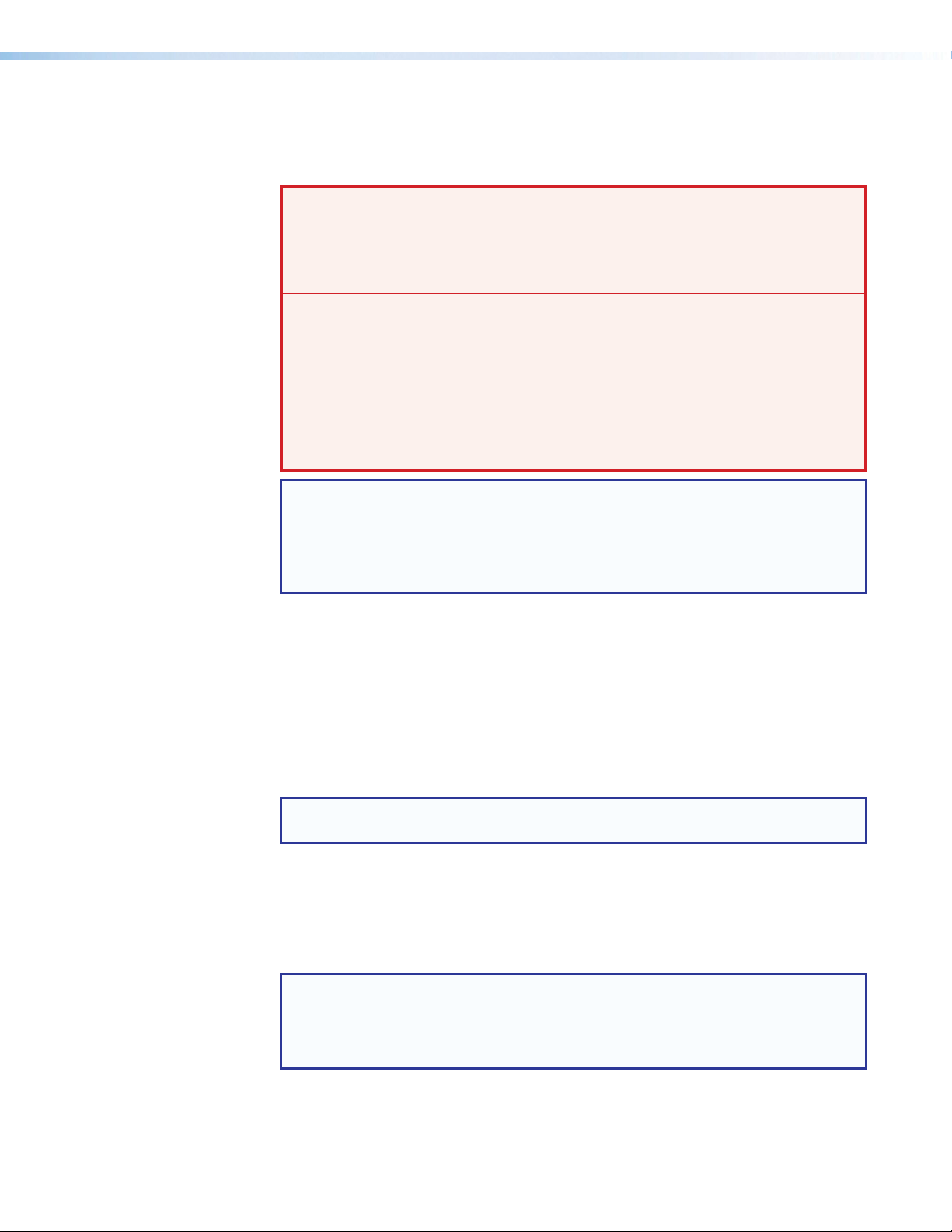
FCC Class A Notice
This equipment has been tested and found to comply with the limits for a Class A digital
device, pursuant to part15 of the FCC rules. The ClassA limits provide reasonable
protection against harmful interference when the equipment is operated in a commercial
environment. This equipment generates, uses, and can radiate radio frequency energy and,
if not installed and used in accordance with the instruction manual, may cause harmful
interference to radio communications. Operation of this equipment in a residential area is
likely to cause interference. This interference must be corrected at the expense of the user.
Class 1 Laser Product
Any service to this product must be carried out by Extron Electronics and its qualified
service personnel.
CAUTION: Using controls, making adjustments, or performing procedures in a manner
other than what is specified herein may result in hazardous radiation exposure.
NOTE: For more information on safety guidelines, regulatory compliances, EMI/EMF
compatibility, accessibility, and related topics, see the “Extron Safety and
Regulatory Compliance Guide” on the Extron website.
Produit laser de classe1
Si ce produit a besoin d’un quelconque entretient, celui-ci doit être fait par
ExtronElectronics et son personnel qualifié.
ATTENTION : L’utilisation de commandes, la réalisation de réglages, ou l’exécution de
procédures de manière contraire aux dispositions établies dans le présent document,
présente un risque d’exposition dangereuse aux radiations.
Remarque: Pour plus d'informations sur les directives de sécurité, les conformités de
régulation, la compatibilité EMI/EMF, l'accessibilité, et les sujets en lien, consultez le
«Informations de sécurité et de conformité Extron» sur le site internet d'Extron.
Page 5
Conventions Used in this Guide
Notifications
The following notifications are used in this guide:
WARNING: Potential risk of severe injury or death.
AVERTISSEMENT: Risque potentiel de blessure grave ou de mort.
CAUTION: Risk of minor personal injury.
ATTENTION : Risque de blessuremineure.
ATTENTION:
• Risk of property damage.
• Risque de dommages matériels.
NOTE: A note draws attention to important information.
TIP: A tip provides a suggestion to make working with the application easier.
Software Commands
Commands are written in the fonts shown here:
^AR Merge Scene,,Op1 scene 1,1 ^B 51 ^W^C
[01] R 0004 00300 00400 00800 00600 [02] 35 [17] [03]
Computer responses and directory paths that do not have variables are written in the font
shown here:
Variables are written in slanted form as shown here:
Selectable items, such as menu names, menu options, buttons, tabs, and field names are
written in the font shown here:
Specifications Availability
Product specifications are available on the Extron website, www.extron.com.
EX!*X1&*X2)*X2#*X2! CE}
NOTE: For commands and examples of computer or device responses mentioned
in this guide, the character “0” is used for the number zero and “O” is the capital
letter “o.”
Reply from 208.132.180.48: bytes=32 times=2ms TTL=32
C:\Program Files\Extron
ping xxx.xxx.xxx.xxx —t
SOH R Data STX Command ETB ETX
From the File menu, select New.
Click the OK button.
Extron Glossary of Terms
A glossary of terms is available at http://www.extron.com/technology/glossary.aspx.
Page 6

Contents
Introduction............................................................ 1
Guide Overview .................................................. 1
Product Description ............................................ 1
System Compatibility ...................................... 2
Cable Transmission ......................................... 2
Control Methods ............................................. 3
Features ............................................................. 3
XTP Interconnection Features ......................... 3
Video Features ................................................ 3
Audio Features ............................................... 4
Control Features ............................................. 4
General Features ............................................ 4
Installation .............................................................. 5
Rear Panel Connectors ....................................... 5
XTP Interconnection ....................................... 6
Output Connections ....................................... 6
Control Connections ....................................... 7
Connection Details ............................................. 8
HDMI Connection ........................................... 8
RS-232 and IR Over XTP Communication ...... 9
Power Connection ........................................ 10
Operation .............................................................. 12
Front Panel Features ......................................... 12
HDMI Audio Switch .......................................... 13
Audio Output Overview ..................................... 13
On-Screen Display Menu System ..................... 14
Menu Navigation Using Front Panel
Controls ....................................................... 14
Menu Overview ............................................. 14
Image Reset Submenu ................................. 15
Picture Controls Submenu ............................ 16
User Presets Submenu ................................. 17
Input Configuration Submenu ....................... 18
Output Configuration Submenu .................... 18
Advanced Configuration Submenu ............... 21
Front Panel Lockout Mode (Executive Mode) .... 22
Reset Modes .................................................... 22
SIS Configuration and Control ........................ 23
Host Device Connection ................................... 23
SIS Overview .................................................... 23
Host and Device Communication .................. 23
Device-Initiated Message .............................. 23
Error Responses ........................................... 24
Command and Response Tables Overview ... 24
Symbol Definitions ........................................ 24
Command and Response Tables for SIS
Commands ..................................................... 25
Picture Adjustment Commands .................... 25
Output Configuration Commands ................. 26
Audio Configuration Commands ................... 28
Preset Commands ........................................ 29
Advanced Configuration Commands ............ 29
Device Commands ....................................... 31
Configuration Software ..................................... 32
Software Installation.......................................... 32
Software Download Center Page .................. 32
Software Product Page ................................. 34
Software Connection ........................................ 35
Software Operation........................................... 36
Menu Bar ..................................................... 36
Device Settings ............................................. 39
Reference Information ...................................... 48
Mounting .......................................................... 48
Tabletop Mounting ........................................ 48
Furniture Mounting........................................ 48
Rack Mounting ............................................. 48
Firmware Download .......................................... 49
viiXTP SFR HD 4K Scaling Fiber Receiver • Contents
Page 7

XTP SFR HD 4K Scaling Fiber Receiver • Contents viii
Page 8

Introduction
Ext
XT
XT
Fiber
This section contains general information about this guide and the Extron XTP SFR HD 4K
scaling receiver. Topics in this section include the following:
• Guide Overview
• Product Description
• Features
Guide Overview
This guide provides installation, operation, control, and reference information for the
XTP SFR HD 4K scaling receiver series primarily in point-to-point applications.
NOTE: See an XTP matrix switcher user guide at www.extron.com for matrix
applications.
In this guide, the terms “scaling receiver” and “XTP SFR HD 4K” are used interchangeably to
refer to the XTP SFR HD 4K SM scaling fiber receiver or XTP SFR HD 4K MM scaling fiber
receiver.
Product Description
The Extron XTP SFR HD 4K receives video, audio, bidirectional RS-232 and IR, and
Ethernet signals over a single fiber optic cable. It incorporates Extron Vector 4K scaling
technology to deliver selectable HDMI output resolutions up to 4K. For streamlined
integration, it features on-screen menus, audio de-embedding to digital S/PDIF or analog
stereo audio outputs, and relays for room control. Ethernet extension along with RS-232
and IR insertion allow LAN access and remote AV device control.
The following diagram shows one way the XTP SFR HD 4K can be integrated in an XTP
point-to-point application.
HDMI
POWER
12V
1.0A MAX
ron
P FT HD 4K
P Transmitter
Figure 1. Typical XTP SFR HD 4K Point-to-Point Application
MODEL 80
PC
4K Display
POWER
AUDIO
AUDIO
L
ON
LOOP THRU
OFF
XTP FT HD 4K
HDMI
XTP OUTOVER XTPINPUTS
RS-232 IR
R
Tx Rx TxRx
G
SIGLINK LAN
RESET
XTP IN
POWER
XTP IN
12V
12V
1.0A MAX
--A MAX
SIGLINK
LAN
SIGLINK
LAN
OVER XTP
OVER XTP
RS-232 IR
RS-232 RS-232IR
Tx Rx TxRx
Tx Rx TxRx
G
G
FLAT PANEL
HDMI
AUDIOAUDIO
AUDIOAUDIO
OFF
OFF
HDMI
HDMI
R12ON
S/PDIF
S/PDIF
RESET
RESET
Tx Rx G
XTP FR HD 4K
RELAYS
OUTPUTS
REMOTE
OUTPUTS
RELAYS
L
R12ON
L
Extron
XTP SFR HD 4K
XTP Scaling Receiver
XTP SFR HD 4K Scaling Fiber Receiver • Introduction 1
Page 9

WARNING: Potential risk of severe injury. The XTP SFR HD 4K outputs continuous
invisible light, which may be harmful to the eyes; use with caution.
AVERTISSEMENT :
XTP SFR HD 4K émet une lumière invisible en continu qui peut être dangereux pour
les yeux, à utiliser avec précaution.
• Do not look into the rear panel fiber optic cable connectors or into the fiber optic
cables themselves.
• Ne regardez pas dans les connecteurs de câble fibre optique sur le panneau arrière
ou dans les câbles fibre optique eux-mêmes.
• Plug the attached dust caps into the optical transceivers when the fiber cable is
unplugged.
• Branchez les protections contre la poussière dans l’ensemble émetteur/récepteur
lorsque le câble fibre optique est débranché.
Risque potentiel de blessure grave ou de mort. Le
System Compatibility
The XTP SFR HD 4K is compatible with XTP systems, but the maximum video resolution
may be limited with different XTP devices. See the table below for maximum video
resolutions and refresh rates for various XTP systems.
Output
Non-4K 4K Fiber 4K Twisted
Pair
Analog 1920x1200
@ 60 Hz
Non-4K Digital 2048x1080
@ 60 Hz
4K Fiber 2048x1080
Input
4K Twisted Pair 2048x1080
4K PLUS 2048x1080
@ 60 Hz
@ 60 Hz
@ 60 Hz
1920x1200
@ 60 Hz
2048x1080
@ 60 Hz
4096x2160
@ 24 Hz
4096x2160
@ 24 Hz
4096x2160
@ 24 Hz
1920x1200
@ 60 Hz
2048x1080
@ 60 Hz
4096x2160
@ 24 Hz
4096x2160
@ 30 Hz
4096x2160
@ 30 Hz
4K Plus
1920x1200
@ 60 Hz
2048x1080
@ 60 Hz
4096x2160
@ 24 Hz
4096x2160
@ 30 Hz
4096x2160
@ 60 Hz
Cable Transmission
The devices are further categorized by the type of fiber optic cable, multimode (MM) or
singlemode (SM), which defines the effective range of transmission:
• Multimode — Long distance, up to 700 m (2,297 feet) depending on the fiber cable
• Singlemode — Very long distance, up to 10 km (6.21 miles)
NOTES:
• The multimode and singlemode models are physically and functionally identical with
the exception of the effective range of transmission.
• Different modes are not compatible with each other.
• A color-coded sticker identifies the type of SFP module: orange for multimode and
yellow for singlemode.
XTP SFR HD 4K Scaling Fiber Receiver • Introduction 2
Page 10

Control Methods
Features
XTP Interconnection Features
To directly control the scaling receiver, use one of the following methods:
• On-screen display (OSD) menu (see On-Screen Display Menu System on page 14)
• Simple Instruction Set (SIS) commands (see SIS Configuration and Control on
page 23)
• XTP System Configuration Software (see Configuration Software on page 32)
Certain features can also be controlled through an XTP matrix switcher (see the XTP matrix
switcher user guide at www.extron.com).
• Reliable cable infrastructure — Accepts video with embedded audio, bidirectional
RS-232 and IR control, and Ethernet over one fiber optic cable.
• Bidirectional RS-232 and IR insertion — Controls a remote display without the need
for additional cabling through bidirectional RS-232 control and IR signals inserted into
the XTP output.
• Ethernet extension — Reduces independent network drops required within a system
with centralized 10/100 Ethernet communication.
• Signal and link status LED indicators for XTP ports — Provide a means for
validating signal flow and operation from transmitter to receiver, allowing quick
identification of connectivity issues.
Video Features
• Advanced Extron Vector 4K scaling technology — Ensures critical-quality 4K
imagery, with best-in-class image upscaling and downscaling, enhanced color
accuracy, and picture detail.
• Video Scaling — Scales HDMI, DVI, RGB, HD component video, and standard
definition video received from XTP devices.
• Selectable output rates — Outputs selected rates from 640x480 to 4K (3840x2160)
using the on-screen menu system or via RS-232 or USB control.
• Scaler bypass mode — Allows scaling to be bypassed to support unprocessed
transmission of 3D, UHD 3840x2160/60 4:2:0, 4096x2160/24, and other formats.
• HDMI specification features — Support data rates up to 10.2 Gbps, 3D, and HD
lossless audio formats.
• HDCP compliance — Ensures display of content-protected media and interoperability
with other HDCP-compliant devices.
• HDMI to DVI Interface Format Correction — Automatically reformats HDMI source
signals for output to a connected DVI display.
• Aspect ratio control — Controls the aspect ratio of the video output by selecting a
FILL mode, which provides a full screen output, or a FOLLOW mode, which preserves
the original aspect ratio of the input signal.
XTP SFR HD 4K Scaling Fiber Receiver • Introduction 3
Page 11

Audio Features
• Multiple embedded audio formats — Supports a broad range of multi-channel audio
signals, providing reliable operation with HDMI devices.
• HDMI audio de-embedding with multi-channel digital S/PDIF audio and analog
stereo audio outputs — Supports digital HDMI audio as a balanced or unbalanced
analog stereo signal on captive screw connectors or an S/PDIF connector.
• Audio output volume adjustment and muting
• Selectable HDMI audio pass-through — Enables or disables audio signal
pass-through on the HDMI output from a rear panel toggle switch.
Control Features
• Front panel USB configuration port
• Contact closure device control — Enables control of room functions such as
projector lifts, screen operations, and other environmental controls.
• Extron XTP System Configuration Software compatibility — Allows for easy setup
and commissioning.
• On-screen menus — Allow for easy system setup using the front panel controls.
• RS-232 control — Enables the use of serial commands for integration into a control
system. Extron products use the SIS - Simple Instruction Set command protocol, a set
of basic ASCII commands that allow for quick and easy programming.
General Features
• XTP compatibility — Provides a flexible signal switching and distribution solution that
is completely integrated, ensuring reliable routing of multiple digital and analog formats.
• EDID Minder — Automatically manages EDID communication between connected
devices. It ensures that all sources power up properly and reliably outputs content for
display.
• Key Minder — Authenticates and maintains continuous HDCP encryption between
input and output devices to ensure quick and reliable switching in professional AV
environments, while enabling simultaneous distribution of a single source signal to one
or more displays.
• EDID and HDCP transmission — Supports DDC channels that are actively buffered,
allowing continuous communication between source and display.
• HDCP Visual Confirmation — Provides a green signal when encrypted content is sent
to a non-compliant display.
• Image freeze control — Freezes a live image through RS-232 or USB control.
• Internal test patterns — Include five test patterns for calibration and setup.
• Output Standby Mode — Automatically mutes video and sync output to the display
device when no active input signal is detected.
• Front panel security lockout — Allows security lockout of front panel buttons except
for input selection and volume adjustment.
• LockIt HDMI cable lacing brackets — Secure HDMI cables to the HDMI connectors.
• 1” (2.5 cm) high, half rack width metal enclosure — Allows for discreet placement
and concealment.
• Highly reliable, energy-efficient external universal power supply included —
Provides worldwide power compatibility, with high demonstrated reliability and low
power consumption for reduced operating costs.
XTP SFR HD 4K Scaling Fiber Receiver • Introduction 4
Page 12
Installation
This section contains installation procedures for the XTP SFR HD 4K and wiring details.
Topics in this section include the following:
• Rear Panel Connectors
• Connection Details
Rear Panel Connectors
IABC DEFG H
POWER
12V
1.0 A MAX
Interconnection
XTP IN
SIG LINK
LAN
OVER XTP
RS-232 RS-232IR
Tx Rx Tx Rx
G
AUDIOAUDIO
OFF
HDMI
Output Connectors Control and Power
Connectors
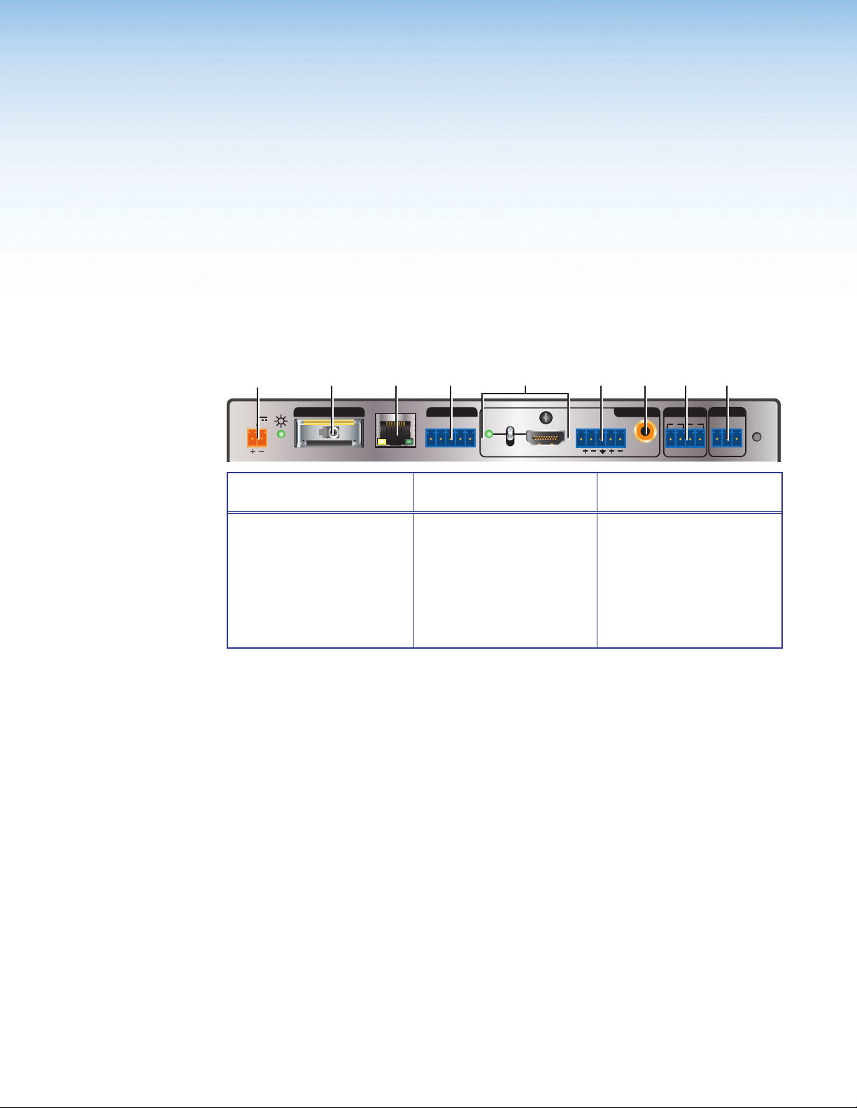
XTP input connector
A
(see page 6)
LAN connector
B
(see page 6)
RS-232 and IR Over
C
XTP connector
(see page 6)
HDMI output
D
connector and audio
switch (see page 6)
Analog audio output
E
connector (see page 7)
S/PDIF audio output
F
connector (see page 7)
Figure 2. XTP SFR HD 4K Rear Panel Connectors
OUTPUTS
L
R12ON
RELAYS
S/PDIF
Connectors
Relay connectors
G
(see page 7)
Remote RS-232
H
connector (see page 7)
Power connector and
I
LED (see page 7)
REMOTE
RESET
Tx Rx G
XTP SFR HD 4K Scaling Fiber Receiver • Installation 5
Page 13
XTP Interconnection
XTP input connector (see figure 2 on the previous page) — Connect an XTP fiber
A
transmitter or XTP matrix switcher to the fiber optic connector.
WARNING: Potential risk of severe injury. The XTP SFR HD 4K outputs
continuous invisible light, which may be harmful to the eyes; use with caution.
AVERTISSEMENT :
XTP SFR HD 4K émet une lumière invisible en continu qui peut être dangereux
pour les yeux, à utiliser avec précaution.
• Do not look into the rear panel fiber optic cable connectors or into the fiber
• Ne regardez pas dans les connecteurs de câble fibre optique sur le panneau
• Plug the attached dust caps into the optical transceivers when the fiber cable is
• Branchez les protections contre la poussière dans l’ensemble
NOTES:
• Different modes are not compatible with each other.
• Ensure the proper fiber cable is used. Typically, singlemode fiber optic cables
Risque potentiel de blessure grave ou de mort. Le
optic cables themselves.
arrière ou dans les câbles fibre optique eux-mêmes.
unplugged.
émetteur/récepteur lorsque le câble fibre optique est débranché.
have a yellow jacket and multimode fiber optic cables have an orange or aqua
jacket.
LAN connector — Connect a control device or device to be controlled to the RJ-45
B
connector labeled LAN for 10/100Base-T Ethernet communication through this passthrough port. LEDs on the connector indicate link and activity status.
RS-232 Over XTP port — To pass bidirectional serial signals between
C
XTP-compatible devices, connect a controlling or controlled device to the 5-pole captive
screw connector. The port includes only the 3 poles labeled “RS-232.”
IR Over XTP port — To transmit and receive IR signals (up to 56 kHz), connect a
controlling or controlled device to the 5-pole captive screw connector. This port includes
the 2 poles labeled “IR” and shares the ground pole with the RS-232 port.
NOTE: RS-232 and IR data can be transmitted simultaneously (see RS-232 and IR
Over XTP Communication on page 9 for wiring details).
Output Connections
HDMI output connector and audio switch — Connect a digital video display to the
D
female HDMI connector. It supports HDMI or DVI (with an appropriate adapter) signals.
See HDMI Audio Switch on page 13 to mute or unmute embedded audio output.
NOTES:
• The maximum cable length is 15 feet (4.6 meters).
• Use Extron LockIt Cable Lacing Brackets to secure HDMI connectors to the
device (see HDMI Connection on the next page).
XTP SFR HD 4K Scaling Fiber Receiver • Installation 6
Page 14
Analog audio output connector (see figure 2 on page 5) — Connect a balanced or
Do not tin the wires!
Balanced Audio Output
Slee
Unbalanced Audio Output
No Ground Here
RS-232
E
unbalanced, stereo or mono audio output device to the 3.5 mm, 5-pole captive screw
connector for analog audio output (see figure 3 for wiring details).
NOTE: If the device is receiving 2-channel LPCM embedded audio on the HDMI
input signal, it is extracted and converted to a stereo analog signal.
Tip
Ring
ves
Tip
Ring
LR
Sleeves
Tip
Tip
No Ground Here
LR
Figure 3. Audio Output Wiring
ATTENTION:
• For unbalanced audio, connect the sleeves to the contact ground. Do not
connect the sleeves to the negative (-) contacts.
• Pour l’audio asymétrique, connectez les manchons au contact au sol. Ne pas
connecter les manchons aux contacts négatifs (–).
S/PDIF audio output connector — Connect an audio device to the female orange
F
RCA connector for digital S/PDIF audio output (see Audio Output Overview on
page 13 for supported audio formats on the S/PDIF output). The type of audio present
on this output is dictated by the following:
• The audio format selected on the source material or device.
• The source device automatically outputting an audio format through EDID.
Control Connections
Relay connectors — Connect equipment that can be controlled via momentary or
G
latching contact, such as projector screens or lifts, to the normally open relays.
ATTENTION:
• Do not exceed 24 V at 1.0 A for each port.
• Ne pas dépasser 24volts à 1,0A pour chaque port.
Remote RS-232 connector — Connect a host device to the 3.5 mm, 3-pole captive
H
screw connector for serial control of the scaling receiver.
Tx Rx G
Figure 4. Remote RS-232 Wiring
Power connector and LED — Connect the external 12 V, 1.0 A power supply to the
I
2-pole captive screw connector (see Power Connection on page 10). The Power LED
lights to indicate the device is receiving power.
Do not tin the wires!
Ground (G)
Receive (Rx)
Transmit (Tx)
Bidirectional
Controlling
Device
Ground (G)
Receive (Rx)
Transmit (Tx)
XTP SFR HD 4K Scaling Fiber Receiver • Installation 7
Page 15
Connection Details
1
HDMI Connection
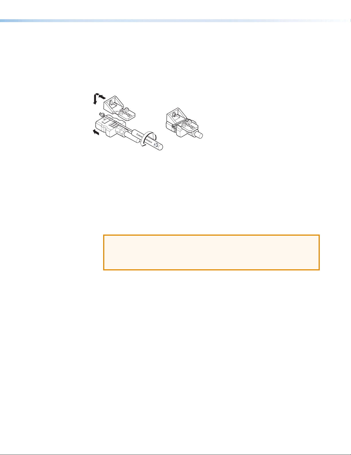
To secure the HDMI cable to the HDMI input connector, use an Extron LockIt Cable Lacing
Bracket and a tie wrap.
3
3
4
2
5
Figure 5. Installing the LockIt Cable Lacing Bracket
1. Plug the HDMI cable into the panel connection (see figure 5, 1).
2. Loosen the HDMI connection mounting screw from the panel (2) enough to allow the
LockIt to be placed over it. The screw does not have to be removed.
3. Place the LockIt on the screw and against the HDMI connector (3), and then tighten
the screw to secure the bracket.
4. Loosely place the included tie wrap around the HDMI connector and the LockIt (4).
5. While holding the connector securely against the cable lacing bracket, use pliers or
similar tools to tighten the tie wrap, then remove any excess length (5).
ATTENTION:
• Connect and pull the tie wraps until they are secure. Do not overtighten.
• Connectez et tirez les serre-câbles jusqu’à ce qu’ils soient sécurisés. Ne pas
trop serrer.
XTP SFR HD 4K Scaling Fiber Receiver • Installation 8
Page 16
RS-232 and IR Over XTP Communication
RS-232 IR
IR Device
vice
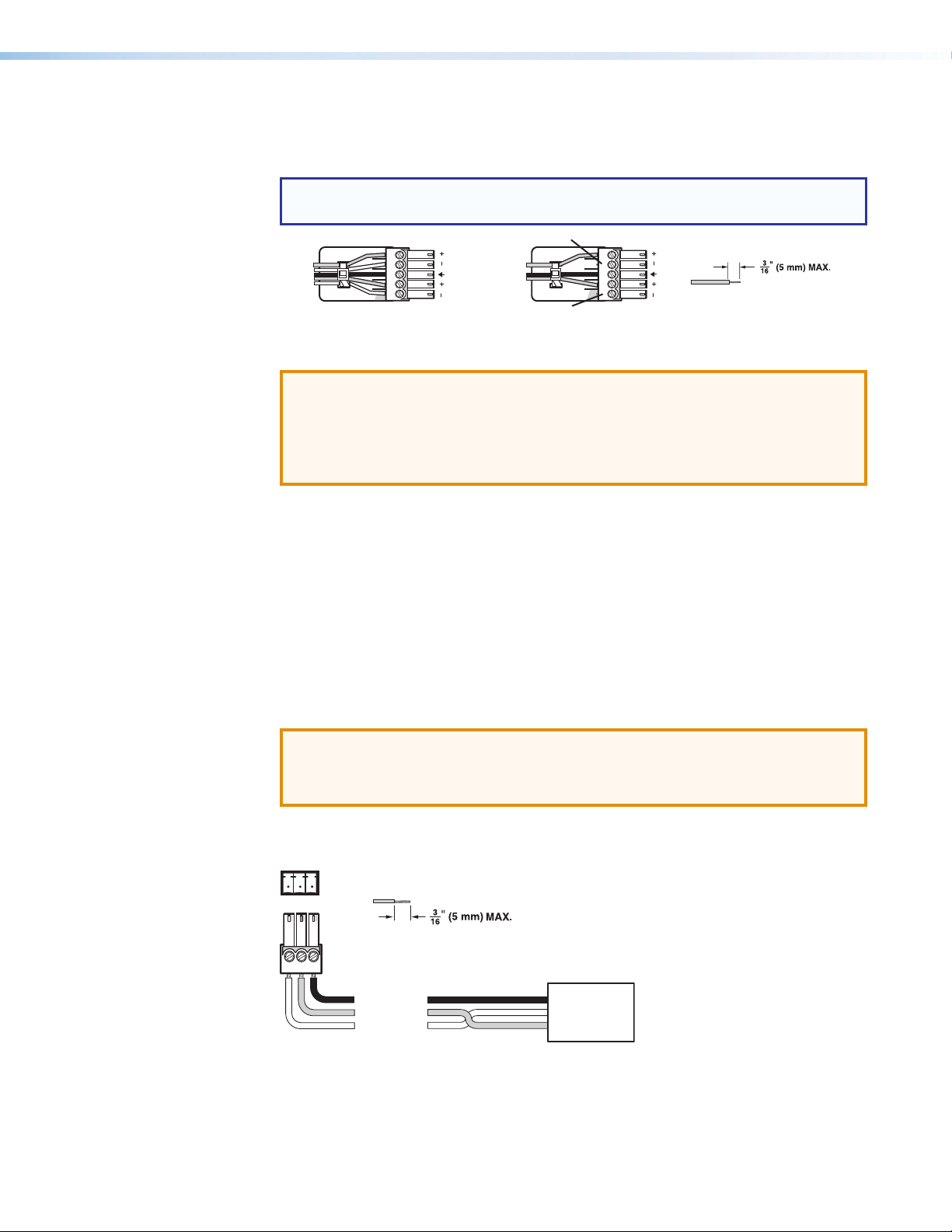
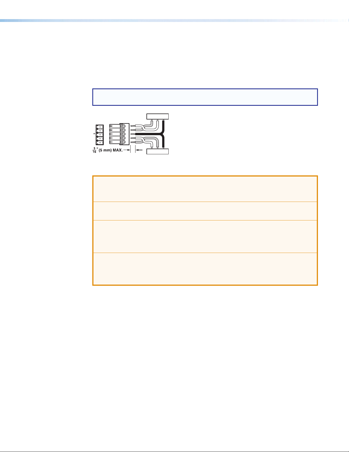
The RS-232 and IR Over XTP connector passes serial signals (such as projector control
signals) and infrared data. To pass bidirectional serial command signals between
XTP-compatible devices, connect a control device to the three poles (Tx, Rx, and G) under
“RS-232” of the 5-pole captive screw connector. To transmit and receive IR signals, connect
a control device to the three poles (G, Tx, and Rx) under “IR.” The ground (G) pole is shared.
NOTE: RS-232 and IR data can be transmitted or received simultaneously (see figure 6
below for wiring considerations).
TxRx
Tx/Rx
Pins
RxTx
G
RxTx
RS-232 De
Figure 6. Wiring the RS-232 and IR Over XTP Connector
ATTENTION: The length of the exposed wires in the stripping process is important.
ATTENTION : La longueur des câbles exposés est importante lorsque l’on entreprend
de les dénuder.
• The ideal length is 3/16 inch (5 mm).
• La longueur idéale est de 5mm (3/16inches).
G
RxTx
G
• If they are any longer, the exposed wires may touch, causing a short circuit
between them.
• S’ils sont un peu plus longs, les câbles exposés pourraient se toucher et provoquer
un court circuit.
• If they are any shorter, the wires can be easily pulled out even if tightly fastened by
the captive screws.
• S’ils sont un peu plus courts, ils pourraient sortir, même s’ils sont attachés par les
vis captives.
XTP SFR HD 4K Scaling Fiber Receiver • Installation 9
Page 17
Power Connection
Output Cord
Tie
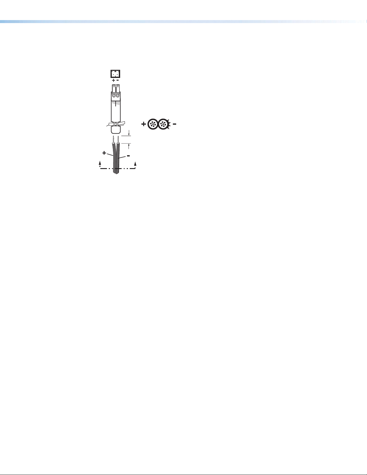
Apply power to the scaling receiver with the provided power supply (if necessary, see
figure 7 for wiring considerations).
Wrap
Smooth
Power Supply
Figure 7. Power Wiring
See the notifications on the next page for other considerations.
2-Pole Captive Screw
Connector
SECTION A–A
3/16”
(5 mm) Max.
Ridges
AA
XTP SFR HD 4K Scaling Fiber Receiver • Installation 10
Page 18

WARNING: Electric shock hazard. The two power cord wires must be kept separate
while the power supply is plugged in. Remove power before wiring.
AVERTISSEMENT :
Risque de choc électrique grave. Les deux cordons d’alimentation
doivent être tenus à l’écart l’un de l’autre quand l’alimentation est branchée. Couper
l’alimentation avant de faire l’installation électrique.
ATTENTION:
• This product is intended for use with a UL Listed power source marked “Class 2”
or “LPS” rated 12 VDC, 1.0 A minimum. Always use a power supply supplied by
or specified by Extron. Use of an unauthorized power supply voids all regulatory
compliance certification and may cause damage to the supply and the unit.
• Ce produit est destiné à une utilisation avec une source d’alimentation listée UL
avec l’appellation « Classe 2 » ou « LPS » et normée 12 Vcc, 1,0 A minimum.
Utilisez toujours une source d’alimentation fournie par Extron. L’utilisation d’une
source d’alimentation non autorisée annule toute conformité réglementaire et peut
endommager la source d’alimentation ainsi que l’unité.
• Unless otherwise stated, the AC/DC adapters are not suitable for use in air handling
spaces or in wall cavities. The installation must always be in accordance with the
applicable provisions of National Electrical Code ANSI/NFPA 70, article 725 and
the Canadian Electrical Code part 1, section 16. The power supply shall not be
permanently fixed to a building structure or similar structure.
• Sauf mention contraire, les adaptateurs AC/DC ne sont pas appropriés pour
une utilisation dans les espaces d’aération ou dans les cavités murales. Cette
installation doit toujours être en accord avec les mesures qui s’applique au National
Electrical Code ANSI/NFPA 70, article 725, et au Canadian Electrical Code,
partie 1, section 16. La source d’alimentation ne devra pas être fixée de façon
permanente à une structure de bâtiment ou à une structure similaire.
• Power supply voltage polarity is critical. Incorrect voltage polarity can damage the
power supply and the unit. The ridges on the side of the cord identify the power
cord negative lead.
• La polarité de la source d’alimentation est primordiale. Une polarité incorrecte
pourrait endommager la source d’alimentation et l’unité. Les stries sur le côté du
cordon permettent de repérer le pôle négatif du cordon d’alimentation.
• The length of the exposed (stripped) copper wires is important. The ideal length is
3/16 inch (5 mm).
• La longueur des câbles exposés est primordiale lorsque l’on entreprend de les
dénuder. La longueur idéale est de 5 mm (3/16 inch).
TIP: Do not tin the stripped power supply leads. Tinned wires are not as secure in the
captive screw connectors and could be pulled out.
XTP SFR HD 4K Scaling Fiber Receiver • Installation 11
Page 19

Operation
After all transmitters, all receivers, and their connected devices are powered up, the system
is fully operational. If any problems are encountered, verify that the cables are routed and
connected properly. If problems persist, call the Extron S3 Sales & Technical Support
Hotline.
This section contains information for front panel operation and configuration of the
XTP SFR HD 4K and configuration through the On-Screen Display (OSD) menu. Topics in
this section include:
• Front Panel Features and Indicators
• HDMI Audio Switch
• Audio Output Overview
• On-Screen Display Menu System
• Front Panel Lockout Mode (Executive Mode)
• Reset Modes
Front Panel Features
ABCDEF G
Extron
Figure 8. XTP SFR HD 4K Front Panel Features
Power LED indicators — Lights when power is applied to the unit. There are two
A
Power LED indicators, one on the front panel and one on the left side of the rear panel.
Configuration connector — If desired, connect a host device to the front panel USB
B
mini-B connector for configuring the switcher.
XTP LED indicators
C
• Signal — Lights when an active XTP input signal is received.
• HDCP — Lights when the received input signal is encrypted.
Audio LED indicators
D
• HBR — Lights when the audio input is high bit rate audio.
• Bitstream — Lights when the embedded audio signal format is a Dolby
• LPCM — Lights when the embedded audio signal is LPCM-2Ch.
• HDMI — Lights when the HDMI audio output is enabled.
• S/PDIF — Lights when the S/PDIF audio output is enabled.
• Analog — Lights when the analog audio output is enabled.
CONFIG
SIGNAL
HDCP
DTS, or 2-Ch Dolby.
HBR
HDMI
AUDIOXTP
BITSTREAM
S/PDIF
LPCM
ANALOG
MENUENTER
ADJUST
XTP SFR HD 4K
®
Digital,
XTP SFR HD 4K Scaling Fiber Receiver • Operation 12
Page 20

Menu button (see figure 8 on the previous page) — Press this button to navigate the
E
OSD menu or enable or disable front panel lockout mode (see Front Panel Lockout
Mode (Executive Mode) on page 22).
Enter button — Press this button to navigate the OSD menu or enable or disable front
F
panel lockout mode (see Front Panel Lockout Mode (Executive Mode)).
Adjustment knobs — Rotate the horizontal ([) or vertical ({) adjustment knob to
G
navigate the on-screen display menu or adjust submenu items.
HDMI Audio Switch
The rear panel HDMI audio switch mutes or unmutes the embedded audio on the HDMI
output connector (see figure 2, D on page 5). The LED next to the switch lights when
HDMI audio is enabled.
• Hold the rear panel HDMI audio switch up until the associated LED indicator lights
(about 1 second) to enable embedded audio on the associated HDMI connector.
• Hold the HDMI audio switch down until the associated LED indicator turns off
(about 1 second) to disable embedded audio on the associated HDMI connector.
The switch returns to the middle position after it has been released to allow continued
control through SIS commands or the XTP System Configuration Software.
Audio Output Overview
By default, an XTP transmitter or matrix switcher prioritizes embedded digital audio over
analog audio. Use SIS commands (see SIS Configuration and Control on page 23) or the
XTP System Configuration Software (see Configuration Software on page 32) to manually
select the audio input.
The following table shows the audio formats available on the different audio output
connectors on the scaling receiver.
Audio Format Availability on Receiver Audio Outputs
Audio Input Format HDMI S/PDIF Analog
2-channel LPCM up to 48 kHz Yes Yes Yes
Multi-channel PCM up to 7.1, 192 kHz Yes
®
Digital® up to 5.1 Yes Yes
Dolby
Dolby Digital EX Yes Yes
Dolby Digital Plus Yes
Dolby TrueHD Yes
Dolby Atmos™ Yes
®
Digital Surround up to 5.1 Yes Yes
DTS
DTS-ES Matrix 6.1 Yes Yes
DTS-ES Discrete 6.1 Yes Yes
DTS-HD Yes
DTS-HD Master Audio™ Yes
Audio Output
XTP SFR HD 4K Scaling Fiber Receiver • Operation 13
Page 21

On-Screen Display Menu System
XTP SFR HD 4K Configuration and adjustments can be performed by using SIS commands
(see SIS Configuration and Control on page 23), the XTP System Configuration Software
(see Configuration Software on page 32), or by using the front panel controls and the
OSD menu. The OSD menu is used primarily when the receiver is first set up.
NOTE: The OSD menu has a fixed time-out of 10 seconds.
Menu Navigation Using Front Panel Controls
• Menu button — Press the Menu button to activate the OSD menu or close submenus
or submenus items.
• Enter button — Press the Enter button to select submenu items or accept changes
to settings.
• Adjustment knobs — Rotate the Horizontal Adjustment ([) knob or Vertical
Adjustment
Menu Overview
The OSD menu contains six submenus with various submenu items for adjusting settings
or viewing device information. Use the Menu, Enter, and adjustment knobs to navigate the
OSD menu.
To open the OSD menu:
1. Connect a display device to the HDMI output connector.
2. Press the Menu button to open the OSD menu.
To navigate the OSD menu:
1. After opening the OSD menu, rotate the adjustment knobs to navigate the six
submenus. The following table shows the six submenus and their respective submenu
items.
Submenus Submenu Items
Image Reset Image reset
Picture
Controls
User Presets Recall Save
Input
Configuration
Output
Configuration
Advanced
Configuration
({) knob to navigate submenus and submenu items and adjust settings.
Horizontal/
vertical position
Total pixels Horizontal/vertical
Resolution Output format Color bit
Test pattern Blank Freeze Aspect
Horizontal/vertical
size
active pixels
Brightness/
contrast
depth
Detail
ratio
System
reset
2. Press the Enter button to open the selected submenu.
3. Rotate the adjustment knobs to navigate the submenu items.
4. Press the Enter button to adjust or view a submenu item or press the Menu button to
return to the list of submenus.
XTP SFR HD 4K Scaling Fiber Receiver • Operation 14
Page 22

To adjust a submenu item:
1. Navigate to an adjustable submenu item and press the Enter button to select the
submenu item.
2. As required, rotate the adjustment knobs or press the Enter button to adjust the
submenu item.
3. Press the Enter button to accept the new value. Press the Menu button to cancel any
pending changes.
To exit the OSD menu:
While in the list of submenus, press the Menu button to exit the OSD menu.
Image Reset Submenu
The Image Reset submenu allows the execution of a one-time reset of the image.
Figure 9. Image Reset Submenu
• Image reset — Press the Enter button to reset shift and size settings to the default
values.
XTP SFR HD 4K Scaling Fiber Receiver • Operation 15
Page 23

Picture Controls Submenu
The Picture Controls submenu allows the adjustment of picture settings.
Figure 10. Picture Controls Submenu
• Image position — Rotate the Horizontal Adjustment knob to adjust the
horizontal (H) position of the image. Rotate the Vertical Adjustment knob to adjust
the vertical (V) position of the image. The default value is 32,768.
• Image size — Rotate the Horizontal Adjustment knob to adjust the horizontal (H)
size of the image. Rotate the Vertical Adjustment knob to adjust the vertical (V) size
of the image. The default value is based on the selected output resolution.
• Brightness and contrast — Rotate the Horizontal Adjustment knob to adjust the
brightness (Bright) of the image. Rotate the Vertical Adjustment knob to adjust the
contrast (Contrast) of the image. The default value is 128.
• Detail — Rotate the adjustment knobs to adjust the detail of the image. The default
value is 64.
XTP SFR HD 4K Scaling Fiber Receiver • Operation 16
Page 24

User Presets Submenu
The User Presets submenu allows the current picture control settings for the selected
input to be saved in user presets. User presets can be saved and recalled later on another
input, allowing them to also be used as aspect ratio or discrete size and center shortcuts.
There are eight user preset slots available. User presets save the following settings:
• Brightness and contrast
• Detail
• Image size and position
Figure 11. User Presets Submenu
• Recall — Rotate the adjustment knobs to select a preset to recall.
• Save — Rotate the adjustment knobs to select a preset to store the current picture
control settings.
XTP SFR HD 4K Scaling Fiber Receiver • Operation 17
Page 25

Input Configuration Submenu
The Input Configuration submenu displays the total pixels and horizontal and vertical
active pixels of the input signal.
Figure 12. Input Configuration Submenu
• Total pixels — Displays the total pixels of the input signal. This is not configurable.
• Active — Displays the active horizontal (H) pixels and vertical (V) lines of the input
signal. These are not configurable.
Output Configuration Submenu
The Output Configuration submenu is used to configure the output resolution and
refresh rate. Output format and color bit depth settings are not configurable from the OSD.
To configure either setting, use SIS commands (see Output Configuration Commands on
page 24) or use the XTP System Configuration Software (see Input/Output tab on
page 40).
Figure 13. Output Configuration Submenu
XTP SFR HD 4K Scaling Fiber Receiver • Operation 18
Page 26

• Resolution — Rotate the adjustment knobs to select a new resolution and refresh rate.
The following table shows the available resolutions and refresh rates. The resolution and
refresh rate can also be changed with SIS commands (see the Output scaler rate SIS
commands on page 27).
Resolution 23.98 Hz 24 Hz 25 Hz 29.97 Hz 30 Hz 50 Hz 59.94 Hz 60 Hz
640x480 •
800x600 •
1024x768 •
1280x768 •
1280x800 •
1280x1024 •
1360x768 •
1366x768 •
1440x900 •
1400x1050 •
1600x900 •
1680x1050 •
1600x1200 •
1920x1200 •
2048x1200 •
2048x1536 •
2560x1080 •
2560x1440 •
2560x1600 •
480p • •
576p •
720p • • • • • •*
1080i • • •
1080p • • • • • • • •
2K (2048x1080) • • • • • • • •
1920x2160 • • • • • • • •
2048x2160 • • • • • • • •
4K (3840x2160) • • • • •
Bypass scaling •
* Default
XTP SFR HD 4K Scaling Fiber Receiver • Operation 19
Page 27

• Output format — Shows the HDMI output format setting. This is not configurable
from the OSD menu. To configure this setting, use SIS commands (see HDMI output
format SIS commands on page 26) or the XTP System Configuration Software (see
Input/Output tab on page 40). The HDMI output format has three components:
• Video format — DVI or HDMI
• Color space — RGB 4:4:4, YUV 4:2:2, or YUV 4:4:4
• Quantization range — full (0-255) or limited (16-235)
The following formats are available:
• Auto (based on display EDID)
• DVI RGB 444
• HDMI RGB 444 Full
• HDMI RGB 444 Limited
• HDMI YUV 444 Full
• HDMI YUV 444 Limited
• HDMI YUV 422 Full
• HDMI YUV 422 Limited
• Color bit depth — Shows the color bit depth setting. This is not configurable from the
OSD menu. To configure this setting, use SIS commands (see Video bit depth SIS
commands on page 26) or the XTP System Configuration Software (see Input/Output
tab on page 40).
XTP SFR HD 4K Scaling Fiber Receiver • Operation 20
Page 28

Advanced Configuration Submenu
The Advanced Configuration submenu is used to set test patterns, screen blanking and
freezing, aspect ratio, and system reset.
Figure 14. Advanced Configuration Submenu
• Test pattern — Rotate the adjustment knobs to select a test pattern. The available
test patterns are Crop, Alternating Pixels, 4x4 Crosshatch, Color Bars, and
Grayscale. The default setting is Off.
Crop Alternating Pixels 4x4 Crosshatch Color Bars Grayscale
Figure 15. Test Pattern Examples
NOTE: All test patterns include a single pixel border.
• Blank — Rotate the adjustment knobs to turn the blank screen feature on or off. When
on, the screen turns black, but the OSD menu is still available.
• Freeze — Rotate the adjustment knobs to freeze or unfreeze the output.
• Aspect ratio — Rotate the adjustment knobs to set the output aspect ratio to Fill or
Follow. When the aspect ratio is set to Fill, the output is sized and centered to fill the
entire output screen. When the aspect ratio is set to Follow, the native aspect ratio of
the input is maintained.
• Factory reset — Press and hold the Enter button to reset the device to factory
defaults. The scaler retains the current firmware version.
XTP SFR HD 4K Scaling Fiber Receiver • Operation 21
Page 29

Front Panel Lockout Mode (Executive Mode)
Executive mode locks all front panel controls (RS-232 and USB control are still available).
To enable or disable executive mode through the front panel, press and hold the Menu and
Enter buttons simultaneously for about 2 seconds or until the Power LED blinks (see Front
Panel Lockout mode SIS commands on page 30 or Configuration Software on
page 32 for remote enabling or disabling of the Front Panel Lockout mode).
Reset Modes
Use the recessed Reset button on the rear panel (see figure 16, A) to return the device to
default settings or restore factory-shipped firmware.
A
POWER
12V
1.0 A MAX
XTP IN
SIG LINK
LAN
OVER XTP
RS-232 RS-232IR
Tx Rx Tx Rx
G
AUDIOAUDIO
OFF
HDMI
L
OUTPUTS
R12ON
S/PDIF
RELAYS
REMOTE
RESET
Tx Rx G
Figure 16. Rear Panel Reset Button
Reset Mode Summary
Mode Activation Result Purpose and Notes
Factory
Firmware
Reset
(mode 1)
Press and hold the recessed
Reset button while applying
power to the device.
NOTE: After this reset,
update the device with the
latest firmware version. Do
not operate the device with
the firmware version that
results from this reset.
The device reverts to the factory
default firmware for a single power
cycle.
NOTE: If this reset was
performed by mistake or
is no longer desired, cycle
power to the device again to
restore the firmware version
running prior to the reset.
Use this reset to return
the firmware to the factory
version temporarily if an
incompatibility issue arises
with the current firmware.
User
Settings
Reset
(mode 5)
Hold down the
Reset button until
the Power LED blinks three times
(over approximately 9 seconds).
Then, press the Reset button
again momentarily (<1 second).
The device reverts to the factory
defaults except for firmware.
• All user modifiable
configurations reset to default
values, including real-time
adjustments.
Use this reset to restart with
the default configuration.
This is equivalent to the
ZXXX SIS command (see the
Reset mode SIS command
on page 31).
• The front panel Power LED
blinks four times in quick
succession during the reset.
XTP SFR HD 4K Scaling Fiber Receiver • Operation 22
Page 30

SIS Configuration and Control
This section contains SIS communication details and SIS commands and responses when
connected directly to an XTP SFR HD 4K. Topics in this section include:
• Host Device Connection
• SIS Overview
• Command and Response Tables for SIS Commands
Host Device Connection
Use a connected computer running the Extron DataViewer utility to send and receive SIS
commands and responses. To connect directly to an XTP SFR HD 4K, connect the computer
to the XTP SFR HD 4K through the front panel USB configuration port (see figure 8, B on
page 12) or the rear panel Remote RS-232 connector (see figure 2, H on page 5). The
protocol for the serial port is as follows: 9600 baud, no parity, 8 data bits, 1 stop bit, no flow
control.
SIS Overview
Host and Device Communication
Device-Initiated Message
SIS commands consist of one or more characters per field. No special characters are
required to begin or end a command sequence. When the XTP SFR HD 4K determines that
a command is valid, it executes the command and sends a response to the host device. All
responses from the receiver to the host end with a carriage return and a line feed
(CR/LF = ]), which signals the end of the response character string. A string is one or more
characters.
When the switcher is connected through the serial port only and a local event occurs, the
device responds by sending a message to the host.
The following copyright message is displayed after a power cycle via RS-232.
(C) Copyright YYYY, Extron Electronics, XTP SFR HD 4K MM Vx.xx, 60-1278-21]
(C) Copyright YYYY, Extron Electronics, XTP SFR HD 4K SM Vx.xx, 60-1278-22]
YYYY is the year. Vx.xx is the firmware version number.
XTP SFR HD 4K Scaling Fiber Receiver • SIS Configuration and Control 23
Page 31

Error Responses
When the XTP SFR HD 4K receives an SIS command and determines that it is valid, it
performs the command and sends the corresponding response to the host device. If the
command is determined invalid or contains invalid parameters, the receiver returns an error
response to the host. The error response codes are:
E10 = Invalid command
E11 = Invalid preset number
E13 = Invalid parameter
E14 = Not valid for this configuration
E17 = Invalid command for signal type
E22 = Busy
Command and Response Tables Overview
The command and response tables for SIS commands list the commands the receiver
recognizes as valid, the responses returned to the host, a description of the command
function or results of executing the command, and some examples of commands in ASCII.
NOTE: Upper and lowercase text can be used interchangeably unless otherwise stated.
Symbol Definitions
The table below shows the hexadecimal equivalent of ASCII characters used in the
command and response tables. Hexadecimal values include two digits. The following
symbols are commonly used throughout the command and response tables.
ASCII and Hexadecimal Conversion Table
Second Hexadecimal Digit
0 1 2 3 4 5 6 7 8 9 A B C D E F
0
1
2
3
4
5
6
First Hexadecimal Digit
7
= Carriage return and line feed (LF)
]
= Carriage return with no line feed
}
=
|
= Space
•
= Escape key
E
W
=
! “ # $ % & ‘ ( ) * + , - . /
•
0 1 2 3 4 5 6 7 8 9 : ; < = > ?
@ A B C D E F G H I J K L M N O
P Q R S T U V W X Y Z [ \ ] ^ _
` a b c d e f g h i j k l m n o
p q r s t u v w z y z { | } ~
Pipe (can be used interchangeably with the
Can be used interchangeably with the
} character).
E character.
LF
}
E
XTP SFR HD 4K Scaling Fiber Receiver • SIS Configuration and Control 24
Page 32

Command and Response Tables for SIS Commands
Command ASCII Command
(host to XTP)
Picture Adjustment Commands
Contrast
Set contrast
Increase contrast
Decrease contrast
View contrast level
Brightness
Set brightness
Increase brightness
Decrease brightness
View brightness
Detail filter
Set detail level
Increase detail level
Decrease detail level
View detail level
Image reset
Execute an image reset
EX!CONT} ContX!] Set the contrast to X!.
E+CONT} Cont X!]
E-CONT} Cont X!]
ECONT} ContX!]
EX!BRIT} BritX!] Set brightness level to X!.
E+BRIT} BritX!]
E-BRIT} Brit X!]
EBRIT} BritX!]
EX@HDET} HdetX@] Set the detail level to X@.
E+HDET} Hdet X@]
E-HDET} Hdet X@]
EHDET} HdetX@]
A
ASCII Response
(XTP to host)
]
Img
Additional Description
Increase the contrast level by one.
Decrease the contrast level by one.
View the contrast level.
Increase brightness level by one.
Decrease brightness level by one.
View the brightness level.
Increase the detail level by one.
Decrease the detail level by one.
View the detail level.
Reset shift and size settings to the
default values.
NOTES:
X! = Picture adjustment
X@ = Detail filter
0 to 255 (128 = default)
0 to 127 (64 = default)
XTP SFR HD 4K Scaling Fiber Receiver • SIS Configuration and Control 25
Page 33

Command ASCII Command
(host to XTP)
Horizontal shift
Set horizontal shift
Increase horizontal shift
Decrease horizontal shift
View horizontal shift
Vertical shift
Set vertical shift
Increase vertical shift
Decrease vertical shift
View vertical shift
Horizontal size
Set horizontal size
Increase horizontal size
Decrease horizontal size
View horizontal size
Vertical size
Set vertical size
Increase vertical size
Decrease vertical size
View vertical size
EX#HCTR} HctrX#] Set horizontal position to X#.
E+HCTR} HctrX#]
E-HCTR} HctrX#]
EHCTR} HctrX#]
EX#VCTR} VctrX#] Set vertical position to X#.
E+VCTR} VctrX#]
E-VCTR} VctrX#]
EVCTR} VctrX#]
EX$HSIZ} HsizX$] Set image width to X$.
E+HSIZ} HsizX$]
E-HSIZ} HsizX$]
EHSIZ} HsizX$]
EX$VSIZ} VsizX$] Set image height to X$.
E+VSIZ} VsizX$]
E-VSIZ} VsizX$]
EVSIZ} VsizX$]
Output Configuration Commands
HDMI output format
Set HDMI output format
View HDMI output format
Video bit depth
Set video bit depth
View video bit depth
EX%VTPO} VtpoX%]
EVTPO} VtpoX%]
EV X^ BITD} BitdVX^]
EVBITD} BitdVX^]
ASCII Response
(XTP to host)
Additional Description
Shift the image right by one.
Shift the image left by one.
View the horizontal position.
Shift the image down by one.
Shift the image up by one.
View the vertical position.
Increase the image width by one.
Decrease the image width by one.
View the image width.
Increase the image height by one.
Decrease the image height by one.
View the image height.
Set the video format (DVI or
HDMI), color space (RGB 4:4:4,
YUV 4:2:2, or YUV 4:4:4), and
quantization range (full or limited).
Set the video bit depth.
NOTES:
X# = Horizontal or vertical shift
X$ = Horizontal or vertical size
X% = HDMI output format
X^ = Video bit depth
0 to 65535 (32768 = default)
0 to 65535 (32768 = default)
0 = auto (default)
1 = DVI RGB 444
2 = HDMI RGB 444 “Full”
3 = HDMI RGB 444 “Limited”
4 = HDMI YUV 444 “Full”
5 = HDMI YUV 444 “Limited”
6 = HDMI YUV 422 “Full”
7 = HDMI YUV 422 “Limited”
0 = auto (default)
1 = 8 bit
XTP SFR HD 4K Scaling Fiber Receiver • SIS Configuration and Control 26
Page 34

Command ASCII Command
(host to XTP)
ASCII Response
(XTP to host)
Additional Description
Output scaler rate
Set output rate
EX&RATE} Rate X&]
Select output resolution and refresh rate.
NOTE: Bypass mode outputs the input signal without being scaled like a standard non-scaling receiver. This
prevents higher resolutions from being scaled to a lower resolution and potential input and output sync
issues in 3D applications.
View output rate
ERATE} RateX&]
Show selected output rate.
NOTES:
X& = Output scaler rate and refresh rate
See the table below (
37 = default)
Resolution 29.98 Hz 24 Hz 25 Hz 29.97 Hz 30 Hz 50 Hz 59.94 Hz 60 Hz
640x480
800x600
1024x768
1280x768
1280x800
1280x1024
1360x768
1366x768
1440x900
1400x1050
1600x900
1680x1050
1600x1200
1920x1200
2048x1200
2048x1536
2560x1080
2560x1440
2560x1600
480p
576p
720p
1080i
1080p
2K (2048x1080)
1920x2160
2048x2160
4K (3840x2160)
Bypass scaling
31
32 33 34 35 36 37
38 39 40
41 42 43 44 45 46 47 48
49 50 51 52 53 54 55 56
57 58 59 60 61 62 63 64
65 66 67 68 69 70 71 72
73 74 75 76 77
199
29 30
10
11
12
13
14
15
16
17
18
19
20
21
22
23
24
25
26
27
28
XTP SFR HD 4K Scaling Fiber Receiver • SIS Configuration and Control 27
Page 35

Command ASCII Command
(host to XTP)
Audio Configuration Commands
Volume
Set volume
Increase volume level
Decrease volume level
View volume level
X*V VolX*] Set output volume to X*.
+V
-V
V
Audio mute
Set mute
View mute status
X(Z AmtX(]
Z
NOTES:
X* = Volume
X*
dB of
Attenuation
0
1
2
3
4
5
6
7
8
9
10
11
12
13
14
15
16
17
18
19
20
21
76 0%
63 5.5%
62 7.0%
61 8.5%
60 10.0%
59 11.5%
58 13.0%
57 14.5%
56 16.0%
55 17.5%
54 19.0%
53 20.5%
52 22.0%
51 23.5%
50 25.0%
49 26.5%
48 28.0%
47 29.5%
46 31.0%
45 32.5%
44 34.0%
43 35.5%
Output
Volume
X*
22
23
24
25
26
27
28
29
30
31
32
33
34
35
36
37
38
39
40
41
42
43
ASCII Response
(XTP to host)
X*]
Vol
X*]
Vol
X*]
Vol
Additional Description
Increase the audio volume by 1 dB.
Decrease audio volume by 1 dB.
View current volume setting.
Set the audio mute for various outputs.
X(]
Amt
0 to 64 in 1 dB steps (64 = default)
dB of
Attenuation
Output
Volume
42 37.0%
41 38.5%
40 40.0%
39 41.5%
38 43.0%
37 44.5%
36 46.0%
35 47.5%
34 49.0%
33 50.5%
32 52.0%
31 53.5%
30 55.0%
29 56.5%
28 58.0%
27 59.5%
26 61.0%
25 62.5%
24 64.0%
23 65.5%
22 67.0%
View the audio mute status.
X*
44
45
46
47
48
49
50
51
52
53
54
55
56
57
58
59
60
61
62
63
64
21 68.5%
dB of
Attenuation
20 70.0%
19 71.5%
18 73.0%
17 74.5%
16 76.0%
15 77.5%
14 79.0%
13 80.5%
12 82.0%
11 83.5%
10 85.0%
9 86.5%
8 88.0%
7 89.5%
6 91.0%
5 92.5%
4 94.0%
3 95.5%
2 97.0%
1 98.5%
0 100.0%
Output
Volume
X( = Audio mute
0 = unmute (default)
1 = mute HDMI audio output
2 = mute analog audio output
3 = mute HDMI and analog audio outputs
4 = mute S/PDIF audio output
5 = mute S/PDIF and HDMI audio outputs
6 = mute S/PDIF and analog audio outputs
7 = mute all audio outputs
XTP SFR HD 4K Scaling Fiber Receiver • SIS Configuration and Control 28
Page 36

Command ASCII Command
(host to XTP)
Preset Commands
User presets
Recall preset
Save preset
X1). RprX1)] Recall user preset X1).
X1), SprX1)]
Advanced Configuration Commands
Video Mute
Mute video and sync
Mute video
Unmute video
View mute status
Aspect ratio
Set aspect ratio to Fill
Set aspect ratio to Follow
View aspect ratio setting
Test pattern
2B
1B
0B
B
E1ASPR} Aspr1]
E2ASPR} Aspr2]
EASPR} Aspr X1@]
ASCII Response
(XTP to host)
]
Vmt2
]
Vmt1
]
Vmt0
X1!]
Vmt
Additional Description
Save the current settings to
user preset X1).
Mute the video and sync.
Mute the selected input.
Display the selected input.
View mute status.
Fill the entire output raster.
Use the native aspect ratio of
the input.
View the current aspect ratio
setting.
NOTE: See figure 15 on page 21 for examples of the available test patterns.
Set pattern
View test pattern
Freeze
Enable
Disable
View freeze status
NOTES:
X1) = User preset
X1! = Video mute
X1@ = Aspect ratio
X1# = Test pattern
X1$ = Freeze
X1#J TstX1#] Set the test pattern to X1#.
J
1F
0F
F
X1#]
Tst
]
Frz1
]
Frz0
X1$]
Frz
1 to 8
0 = unmute (default)
1 = mute video
2 = mute video and sync
1 = fill (default)
2 = follow
0 = off (default)
1 = crop
2 = alternating pixels
3 = crosshatch
4 = colorbars
5 = greyscale
0 = unfreeze image
1 = freeze image
View the current test pattern.
Freeze the selected input.
Unfreeze the selected input.
View the freeze status.
XTP SFR HD 4K Scaling Fiber Receiver • SIS Configuration and Control 29
Page 37

Command ASCII Command
(host to XTP)
Screen saver
Set timeout duration
View timeout duration
Switch mute
NOTE: The basic mute specifies the mute duration when switching. The advanced mute adds an additional
mute to help compensate for switching between different input resolutions.
EX1%SSAV} Ssav X1%*X1^]
ESSAV} Ssav X1%*X1^]
ASCII Response
(XTP to host)
Additional Description
Set the required duration of
inactivity before the screen
saver activates.
View the required duration of
inactivity before the screen
saver activates and how
much time is left before it
activates.
Set switch mute
View switch mute setting
Front Panel Lockout (Executive) mode
Enable executive mode
Disable executive mode
View executive mode status
HDCP mode
Set HDCP mode
View HDCP mode setting
NOTES:
X1% = Screen saver timeout duration
X1^ = Time in seconds until timeout
X1& = Basic mute
X1* = Advanced mute
X1( = Front panel lockout mode
X2) = HDCP mode
EX1&*X1*AUTB} AutbX1&*X1*]
EAUTB} Autb X1&*X1*]
1X
0X
X
Exe1
Exe0
Exe
]
]
X1(]
Set the mute duration
between switching inputs.
View the basic and advanced
mute durations between
switching inputs.
Lock the entire front panel.
Unlock the front panel.
View the executive mode
status.
ES X2) HDCP} HdcpSX2)] Set the HDCP mode to X2).
ESHDCP} HdcpSX2)]
0 = never time out (default)
1-255 in 1 second steps
0 = screen saver never times out or the screen saver is
currently activated
1-255 in 1 second steps
0-255 where 1 step = 100 ms or 10 steps = 1 s
(0 = default)
0-255 where 1 step = 100 ms or 10 steps = 1 s
(0 = Default)
0 = allow front panel operation
1 = prevent front panel operation
0 = auto or encrypt the output only when required by
the input (default)
1 = always encrypt the output
View the HDCP mode setting.
XTP SFR HD 4K Scaling Fiber Receiver • SIS Configuration and Control 30
Page 38

Command ASCII Command
(XTP to host)
Device Commands
Relay control
Pulse relay
Toggle relay
Turn relay on
Turn relay off
View relay status
Reset mode
System reset
Information requests
View input signal status
View HDMI output status
View firmware version
View firmware build
View part number
X2!*3* X2@O RlyX2! * X2#] Pulse relay X2! for a duration of
X2!*2O RlyX2!* X2#] Toggle relay X2!.
X2!*1O RlyX2!*1] Turn relay X2! on.
X2!*0O RlyX2!*0] Turn relay X2! off.
X2!O RlyX2! * X2#]
EZXXX} Zpx]
0LS
EOHDCP} HdcpOX2%]
Q
*Q
N
ASCII Response
(host to XTP)
X2$]
Frq
]
x.xx
x.xx.xxxx
60-1278-2x
]
]
Additional Description
X2@.
View relay status.
Resets unit to factory default.
View the input signal status.
Query the HDCP status of the
output.
View the firmware version.
View the firmware build version.
View the device part number
where the value for x depends
on the device model.
NOTES:
X2! = Relay
X2@ = Pulse time
X2# = On or off
X2$ = Input signal status
X2% = HDCP status
1 = relay 1
2 = relay 2
1 to 65535 (in 16 ms steps)
0 = off
1 = on
0 = no input
1 = input detected
0, 2, 4, 6 = no sink device detected
1, 3, 5 = sink detected with no HDCP encryption
7 = sink detected with HDCP encryption
XTP SFR HD 4K Scaling Fiber Receiver • SIS Configuration and Control 31
Page 39

Configuration Software
This section contains installation and configuration procedures for the XTP System
Configuration Software to directly configure and control the XTP SR HD 4K. It can also be
configured and controlled remotely through the XTP System Configuration Software and the
XTP matrix switcher (see the XTP System Configuration Software Help file). Topics in this
section include the following:
• Software Installation
• Software Connection
• Software Operation
Software Installation
The XTP System Configuration Software is compatible with most Microsoft Windows
operating systems and available for download on the Extron website, www.extron.com. To
download the software from the Extron website, locate it on the Download Center page or
go to the XTP System Configuration Software product page.
Software Download Center Page
The software Download Center page contains available Extron software to download and
install the XTP System Configuration.
Figure 17. Extron Website Download Page
XTP SFR HD 4K Scaling Fiber Receiver • XTP System Configuration Software 32
Page 40

To download and install the XTP System Configuration Software from this page, perform the
following:
1. On the Extron website, select the Download tab (see figure 17, 1 on the previous
page).
2. On the left sidebar, click the Software link (see figure 17, 2).
TIP: If the XTP System Configuration Software is featured in the left sidebar, click
the XTP System Configuration Software link to go directly to the product
page (see Software Product Page on the next page).
Figure 18. XTP System Configuration Software Download Link
3. Click the X link (see figure 18, 1).
4. Locate the XTP System Configuration Software and click the Download link (see
figure 18, 2) to the right of the product name.
5. Submit any required information to start the download. Note where the file is saved.
6. Open the saved executable (.exe) file.
7. Follow the instructions that appear on the screen to install the program.
XTP SFR HD 4K Scaling Fiber Receiver • XTP System Configuration Software 33
Page 41

Software Product Page
The software product page contains information about the software.
Figure 19. XTP System Configuration Software Product Page
To download and install the XTP System Configuration Software from this page, perform the
following:
1. In the Search field (see figure 19, 1) type “XTP System Configuration Software.”
2. Press <Enter> on the keyboard or select XTP System Configuration Software from
the drop-down menu.
3. Click the Download button (2).
4. Submit any required information to start the download. Note where the file is saved.
5. Open the saved executable (.exe) file.
6. Follow the instructions that appear on the screen to install the program.
XTP SFR HD 4K Scaling Fiber Receiver • XTP System Configuration Software 34
Page 42

Software Connection
To connect the software directly to the XTP SFR HD 4K , connect the computer running the
software to the configuration connector (see figure 8, B on page 12).
it.
Figure 20. Connections Screen
To connect to a device:
1. Open the XTP System Configuration Software.
2. On the Connections screen in the XTP Configuration Software, select the USB radio
button (see figure 20, 1).
3. From the displayed list, select the connected device to be controlled (2).
4. Click the Connect button (3). The Device Settings screen opens (see Device
Settings on page 39).
XTP SFR HD 4K Scaling Fiber Receiver • XTP System Configuration Software 35
Page 43

Software Operation
Menu Bar
The menu bar contains three menus for configuring software settings.
File menu
The File menu contains options for disconnecting from the XTP device and exiting the
program. To access the menu, click the File menu.
Figure 21. File Menu
Disconnect
This option disconnects the connected device from the XTP System Configuration Software.
From the File menu, select Disconnect. The Connections screen opens.
NOTE: If the device is already disconnected, the Disconnect option is disabled until a
device is connected.
Exit
This option disconnects the XTP device from the software and closes the application.
From the File menu, select Exit. The application closes.
Tools menu
The Tools menu contains an option for updating firmware. To access this menu, click the
Tools menu.
Figure 22. Tools Menu
NOTE: The Backup and Restore and Commissioning Report options are not
available when the XTP System Configuration Software is directly connected to
the device. See an XTP matrix switcher user guide (www.extron.com) for more
information on these features.
XTP SFR HD 4K Scaling Fiber Receiver • XTP System Configuration Software 36
Page 44

Update Firmware
This option uploads firmware from the PC to the connected device. If necessary, download
firmware from the Extron website (see Firmware Download on page 49).
1. From the Tools menu, select Update Firmware. A dialog box opens to ask permission
to disconnect from the device.
Figure 23. Confirm Disconnect Dialog Box
2. Click the Yes button to disconnect from the device and continue with the firmware
update process. The Update Firmware dialog box opens.
Figure 24. Update Firmware Dialog Box
3. Click one of the following options:
• Select file from computer — Uploads a manually selected firmware file saved
on the connected computer.
• Check network for updates — Checks the connected network for firmware
updates. If any are found, click the Update X Devices button to update the
firmware for the applicable connected devices or click Save File to Computer to
save the firmware file to the connected computer.
4. Click the Close button when finished.
Software Preference
This option resets all disabled confirmation dialogs to the default settings.
1. From the Tools menu, select Software Preference. The Software Preference
dialog box opens.
Figure 25. Software Preference Dialog Box
2. Click the Reset button. The dialog box closes.
XTP SFR HD 4K Scaling Fiber Receiver • XTP System Configuration Software 37
Page 45

Help menu
The Help menu contains a way to access XTP System Configuration Software information,
a link to the help file, and a link to the Extron website.
Figure 26. Help Menu
NOTE: The Tutorial (System Configuration) option is not available when the XTP
System Configuration Software is directly connected to the device.
About the Software
This option provides basic information about the XTP System Configuration Software,
including version number and copyright information.
Figure 27. About - XTP Dialog Box
1. From the Help menu, select About the Software. The About dialog box opens.
2. Click the Details button for more information.
3. Click the Ok button to close the dialog box.
Help
This option opens the XTP System Configuration Software Help file in a web browser.
From the Help menu, select Help.
Extron Website
This option opens the Extron website in a web browser.
From the Help menu, select Extron Website.
XTP SFR HD 4K Scaling Fiber Receiver • XTP System Configuration Software 38
Page 46

Device Settings
The Device Settings screen allows a user to view and edit various device settings for
the receiver directly connected to the PC running the XTP software. Click the Device
Settings
Settings
icon (see figure 28, 1) on the Global Navigation Bar to open the Device
screen.
Figure 28. Device Settings Screen
AV Controls panel
The AV Controls panel, located on the left, is used to perform audio or video mutes.
NOTE: The mute buttons turn red when they are enabled.
Video mute — Click the Video Mute button to mute or unmute the video output.
2
Audio mute — Click the Audio Mute button to mute or unmute the audio output.
3
Audio and video mute — Click the AV Mute button to mute or unmute audio and
4
video output.
Freeze — Click the Freeze button to freeze the current video frame.
5
XTP SFR HD 4K Scaling Fiber Receiver • XTP System Configuration Software 39
Page 47

Input/Output tab
Click the Input/Output tab (see figure 29, 1) to open the Input/Output screen. This
screen contains input and output configurations as well as relay controls.
Figure 29. Input/Output Tab
Input panel
The Input panel on the Input/Output screen is used to set the aspect ratio.
Aspect Ratio — From the Aspect Ratio drop-down list, select Fill or Follow.
2
• Fill — Scales the input signal to fill the entire video output.
• Follow — Maintains the signal aspect ratio, with respect to the current output
resolution.
XTP SFR HD 4K Scaling Fiber Receiver • XTP System Configuration Software 40
Page 48

Output panel
The Output panel on the Input/Output screen is used to set the resolution, refresh rate,
and test pattern.
Resolution (see figure 29 on the previous page) — From the Resolution drop-down
3
list, select the desired resolution.
Refresh Rate — From the Refresh Rate drop-down list, select the desired refresh
4
rate.
Output Format — Sets the output format to a specific setting or to automatically select
5
a format based on the display EDID.
Video Bit Depth — Sets the color bit depth of the output signal.
6
Test Pattern — From the drop-down list below the test pattern preview, select the
7
desired test pattern (see figure 15 on page 21 for examples of the available test
patterns).
Relay Control panel
The Relay Control panel on the Input/Output screen toggles or pulses relay 1 or 2.
Status — Displays whether the relay is open or closed.
8
Toggle — Click the Toggle button in the desired relay panel to toggle either relay open
9
or closed.
Pulse — In the desired Relay panel, select a length of time from the Duration field.
¢
Click the Pulse button to pulse the relay for the time specified in the Duration field.
XTP SFR HD 4K Scaling Fiber Receiver • XTP System Configuration Software 41
Page 49

Video tab
Click the Video tab to open the Video screen. This screen contains picture control settings
and user preset management options.
Figure 30. Video Tab
Picture Control panel
The Picture Control panel on the Video screen is used to adjust brightness, contrast,
and detail settings. Adjust picture control settings in one of the following ways:
• Click and drag the handle of the slider for the desired setting.
• Click in the desired field to the right of the slider and enter a new value.
• Click the Up and Down arrows to the right of the desired setting.
Brightness — Adjust the brightness level of the output.
1
Contrast — Adjust the contrast level of the output.
2
Detail — Adjust the detail level of the output.
3
User Presets panel
User presets save picture control settings that can be recalled later.
Save Preset — Select a preset from the list of presets and click the Save Preset
4
button. The current settings are saved.
Recall Preset — Select the desired preset from the list of presets and click the Recall
5
Preset
button.
XTP SFR HD 4K Scaling Fiber Receiver • XTP System Configuration Software 42
Page 50

Size and Position tab
Click the Size/Position tab (see figure 31, 1) to open the Size and Position screen.
This screen contains several different ways to adjust the size and position of the output.
Figure 31. Size/Position Tab
To adjust the size and position graphically:
If desired, click the Lock Aspect Ratio check box (2) to constrain proportions.
1. Click and drag the drag points of the sample image in the Preview box (3) to resize
the image within the designated space (defined by the black area in figure 31).
2. Click anywhere inside the sample image and drag it anywhere within the Preview box.
To adjust the size and position numerically:
1. Enter a value or click the Up and Down arrows in the Horizontal Size and Vertical
Size
fields (4).
2. Enter a value or click the Up and Down arrows in the Horizontal Position and
Vertical Position fields (
To reset all position and size settings to default values:
Click the Image Reset button (5).
4
).
XTP SFR HD 4K Scaling Fiber Receiver • XTP System Configuration Software 43
Page 51

Audio tab
Click the Audio tab (see figure 32, 1) to open the Audio screen. This screen contains
audio output settings.
Figure 32. Audio Tab
Output panel
The Output panel on the Audio screen is used to mute or unmute all audio output and
control volume on the analog audio output.
Mute All — Click the Mute All button to mute or unmute all audio output. When
2
muted, the button turns red.
Volume slider — Click and drag the handle of the Volume slider, enter a value in the
3
Volume field, or click the Up and Down arrows to adjust analog audio output volume.
Analog audio for DVI displays — Select the check box below the Volume slider to
4
send analog audio to a display receiving DVI signals.
NOTE: When this check box is selected, Extron EDID Minder does not show the
EDID information of the connected display. It shows a 720p Extron EDID.
XTP SFR HD 4K Scaling Fiber Receiver • XTP System Configuration Software 44
Page 52

General tab
Click the General tab (see figure 33, 1) to open the General screen. This screen contains
executive mode and video and sync settings.
Figure 33. General Tab
Executive Mode panel
The Executive Mode panel on the General screen is used to enable or disable front panel
lockout mode (executive mode).
Unlock front panel — Click the Unlock Front Panel radio button (default) to disable
2
executive mode and allow full use of the receiver front panel.
Lock front panel — Click the Lock Front Panel radio button to enable executive
3
mode and lock the front panel.
NOTE: In executive mode, access to the OSD menu is disabled.
Mute Video and Sync panel
The Mute Video and Sync panel on the General screen is used to mute or unmute
output video and sync.
Mute video and sync — Click the Mute Video and Sync button to mute the active
4
video and disable sync on the output.
XTP SFR HD 4K Scaling Fiber Receiver • XTP System Configuration Software 45
Page 53

Screen Saver panel
The Screen Saver panel on the General screen is used to enable or disable a screen
saver. When enabled, the output sync is disabled after a specified amount of time.
Never (see figure 33 on the previous page) — Click the Never radio button to disable
5
the screen saver setting.
Duration — Enter a value in the After: field, or click the Up and Down arrows to
6
specify a duration of inactivity before a screen saver is activated. The duration is set in
seconds.
HDCP Mode panel
The HDCP Mode panel on the General screen is used to set HDCP encryption of the output
signal.
Follow — Click the Follow radio button to set the HDCP encryption of the output
7
signal to follow the input signal setting.
Always Encrypt Output — Click the Always Encrypt Output radio button to always
8
encrypt the output regardless of the encryption status of the input signal.
Switch Mute panel
The Switch Mute panel on the General screen is used to enable or disable mutes during
switching.
Basic mute — Select the Enable check box in the Basic Mute panel to mute the
9
output during switching.
If enabled, enter a value in the associated Duration: field, or click the Up and Down
arrows to specify a mute duration between switching. The duration is set in 0.5 second
increments.
Advanced mute — Select the Enable check box in the Advanced Mute panel to add
¢
an additional mute to help compensate for switching between different input resolutions.
If enabled, enter a value in the associated Duration: field, or click the Up and Down
arrows to specify a duration of the additional mute. The duration is set in 0.5 second
increments.
Factory Reset
Factory Reset — Click the Factory Reset button to reset the receiver to factory
£
settings (except for firmware).
NOTE: This is the same as the E ZXXX SIS command (see the Reset mode SIS
command on page 31).
XTP SFR HD 4K Scaling Fiber Receiver • XTP System Configuration Software 46
Page 54

Device Information panel
The Device Information panel displays device information and signal status information.
Model — Displays the device model.
1
Firmware Version — Displays the firmware
2
version.
Input Signal Present — Displays the signal
3
presence. The indicator to the left turns green
when there is an input signal present.
Aspect Ratio — Displays the aspect ratio.
4
Resolution — Displays the output resolution
5
and refresh rate.
Output Format — Displays the HDMI output
6
format setting.
Video Bit Depth — Displays the video bit
7
depth setting.
HDMI Audio — Displays the mute status of
8
the HDMI audio output.
S/PDIF Audio — Displays the mute status of
9
the audio on the S/PDIF output.
Analog Audio — Displays the mute status of
¢
the analog audio output.
Analog Audio Volume — Displays the
£
analog audio output volume level.
XTP SFR HD 4K Scaling Fiber Receiver • XTP System Configuration Software 47
Page 55

Reference Information
This section contains mounting information and instructions for downloading firmware.
Topics in this section include the following:
• Mounting
• Firmware Download
Mounting
The XTP SFR HD 4K can be placed on a tabletop or mounted in a rack or underneath a
desk.
Tabletop Mounting
Attach the provided rubber feet to the bottom four corners of the enclosure.
Furniture Mounting
Go to www.extron.com for a list of available furniture mounting kits. To install the device to
furniture, follow the mounting kit instructions.
Rack Mounting
Go to www.extron.com for a list of compatible rack mounting kits. To install the device
in a rack, follow the mounting kit instructions and see the UL guidelines for rack-mounted
devices below.
UL guidelines for rack-mounted devices
The following Underwriters Laboratories (UL) guidelines pertain to the safe installation of the
XTP SFR HD 4K in a rack.
1. Elevated operating ambient temperature — If installed in a closed or multi-unit
rack assembly, the operating ambient temperature of the rack environment may be
greater than room ambient temperature, Therefore, install the XTP SFR HD 4K in an
environment compatible with the maximum ambient temperature (Tma = +122 ˚F,
+50 ˚C) specified by Extron.
2. Reduced air flow — Install the equipment in a rack so that the amount of air flow
required for safe operation of the equipment is not compromised.
3. Mechanical loading — Mount the equipment in the rack so that a hazardous
condition is not achieved due to uneven mechanical loading.
4. Circuit overloading — Connect the equipment to the supply circuit and consider the
effect that circuit overloading might have on overcurrent protection and supply wiring.
Appropriate consideration of equipment nameplate ratings should be used when
addressing this concern.
XTP SFR HD 4K Scaling Fiber Receiver • Reference Information 48
Page 56

5. Reliable earthing (grounding) — Maintain reliable grounding of rack-mounted
equipment. Pay particular attention to supply connections other than direct connections
to the branch circuit (for example, the use of power strips).
Firmware Download
Figure 34. Downloading Firmware from the Extron Website
1. On the Extron website, www.extron.com, click the Download tab (see figure 34, 1).
2. On the left sidebar, click the Firmware link (2).
3. Navigate to the desired product (3).
4. Ensure the available firmware version is a later version than the current one on the
device.
NOTE: The firmware release notes are a PDF file that provides details about the
changes between different firmware versions. The file can be downloaded from the
5. Click the Download link (4) to the right of the desired product.
6. Submit any required information to start the download. Note where the file is saved.
same page as the firmware.
XTP SFR HD 4K Scaling Fiber Receiver • Reference Information 49
Page 57

Extron Warranty
Extron Electronics warrants this product against defects in materials and workmanship for a period of three years
from the date of purchase. In the event of malfunction during the warranty period attributable directly to faulty
workmanship and/or materials, Extron Electronics will, at its option, repair or replace said products or components,
to whatever extent it shall deem necessary to restore said product to proper operating condition, provided that it is
returned within the warranty period, with proof of purchase and description of malfunction to:
USA, Canada, South America,
and Central America:
Extron Electronics
1230 South Lewis Street
Anaheim, CA 92805
U.S.A.
Europe and Africa:
Extron Europe
Hanzeboulevard 10
3825 PH Amersfoort
The Netherlands
Japan:
Extron Electronics, Japan
Kyodo Building, 16 Ichibancho
Chiyoda-ku, Tokyo 102-0082
Japan
China:
Extron China
686 Ronghua Road
Songjiang District
Shanghai 201611
China
Asia:
Extron Asia Pte Ltd
135 Joo Seng Road, #04-01
PM Industrial Bldg.
Singapore 368363
Middle East:
Extron Middle East
Dubai Airport Free Zone
F13, PO Box 293666
United Arab Emirates, Dubai
Singapore
This Limited Warranty does not apply if the fault has been caused by misuse, improper handling care, electrical
or mechanical abuse, abnormal operating conditions, or if modifications were made to the product that were not
authorized by Extron.
NOTE: If a product is defective, please call Extron and ask for an Application Engineer to receive an RA (Return
Authorization) number. This will begin the repair process.
USA: 714.491.1500 or 800.633.9876 Europe: 31.33.453.4040
Asia: 65.6383.4400 Japan: 81.3.3511.7655
Units must be returned insured, with shipping charges prepaid. If not insured, you assume the risk of loss or damage
during shipment. Returned units must include the serial number and a description of the problem, as well as the
name of the person to contact in case there are any questions.
Extron Electronics makes no further warranties either expressed or implied with respect to the product and its quality,
performance, merchantability, or fitness for any particular use. In no event will Extron Electronics be liable for direct,
indirect, or consequential damages resulting from any defect in this product even if Extron Electronics has been
advised of such damage.
Please note that laws vary from state to state and country to country, and that some provisions of this warranty may
not apply to you.
Extron Headquarters
+1.800.633.9876 (Inside USA/Canada Only)
Extron USA - West Extron USA - East
+1.714.491.1500 +1.919.850.1000
+1.714.491.1517 FAX +1.919.850.1001 FAX
Extron Europe
+800.3987.6673
(Inside Europe Only)
+31.33.453.4040
+31.33.453.4050 FAX
© 2017 Extron Electronics All rights reserved. www.extron.com
Extron Asia
+65.6383.4400
+65.6383.4664 FAX
Extron Japan
+81.3.3511.7655
+81.3.3511.7656 FAX
Extron China
+86.21.3760.1568
+86.21.3760.1566 FAX
Extron Middle East
+971.4.299.1800
+971.4.299.1880 FAX
Extron Australia
+61.8.8113.6800
+61.8.8351.2511 FAX
Extron India
1800.3070.3777
Inside India Only
+91.80.3055.3777
+91.80.3055.3737 FAX
 Loading...