

Page 1
Setup Guide — USB HUB4 Series
HUB4 USB MAAP
HUB4 USB AAP
ACTIVITY
ACTIVITY
USB HUB4 MAAP
USB HUB4 AAP
ACTIVITY
ACTIVITY
USB Cable (6’)
To Host
Computer
USB Port
Type A
USB
Type mini B
USB Connector
USB IN
WIRE COLOR
RWGB
+V D- D+
S
IN
OUT
WIRE COLOR
RWGB
IN
OUT
POWER
500mA
12V
Rear
Mounting
Frame
USB HUB4 AAP
Captive
Screw
USB
Connector
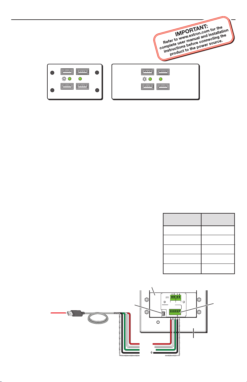
Strip 1” to 2” from the outer jacket
of the USB cable to expose the wires.
Braided Shield / S
Red / +V
White / D
Green / D+
Black /
Wire color Port
Braided shield
V+ (+5 VDC)
Red
S (Shield)
White
D- (Data -)
Green
D+ (Data +)
Black
_ (Ground)
This guide provides basic instructions for setting up the
Extron USB HUB4 Series AAP and MAAP USB Hubs.
Installation
Step 1 — (Optional) Install the wall box or mounting bracket
If using an electrical wall box or a mounting bracket, install it in the wall or furniture. (Refer
to “Wall or furniture mounting” in chapter 2 of the USB HUB4 Series User’s Manual for the
procedure.)
Step 2 — Mount the HUB4 onto a mounting frame
Attach the USB HUB4 AAP or MAAP to an appropriate AAP or MAAP sized mounting frame,
rack space frame, or other Extron architectural product. Refer to “Mounting the hub to a wall
box” or “Mounting the hub to a mounting bracket” in chapter 2 of the user’s manual for details.
Step 3 — Connect the HUB4 to the host computer
For ease of installation, you can connect the USB HUB4 to the host computer in either of the
following ways:
• Using the Type mini B USB connector: Connect a Type A-to-Type mini B cable (provided)
to the USB mini-B connector on the HUB4 rear panel.
• Using the green captive screw USB In port: Remove the
Type B or Type mini B terminator from a Type A-to-B or
Type A-to-mini B USB cable and insert the cable’s wires
into the 5-pole USB In connector as shown below and at
right. (This method may be necessary if space is limited.)
N
Refer to “Connecting to the captive screw USB
connector” in chapter 2 of the user’s manual for more
information.
Choose one of these two methods to connect the
HUB4 to the host computer. Do not connect the host
computer to both HUB4 connectors at the same time.
(Continued on reverse side)
Page 2

Setup Guide — USB HUB4 Series, cont’d
Extron USA - West
Headquarters
+800.633.9876
Inside USA / Canada Only
+1.714.491.1500
+1.714.491.1517 FAX
Extron USA - East
+800.633.9876
Inside USA / Canada Only
+1.919.863.1794
+1.919.863.1797 FAX
Extron Europe
+800.3987.6673
Inside Europe Only
+31.33.453.4040
+31.33.453.4050 FA X
Extron Asia
+800.7339.8766
Inside Asia Only
+65.6383.4400
+65.6383.4664 FAX
Extron Japan
+81.3.3511.7655
+81.3.3511.7656 FAX
Extron China
+400.883.1568
Inside China Only
+86.21.3760.1568
+86.21.3760.1566 FAX
Extron Middle East
+971.4.2991800
+971.4.2991880 FAX
Power Supply
Output cord
USB IN
WIRE COLOR
RWGB
+V D- D+
S
IN
OUT
WIRE COLOR
RWGB
+V D- D+
S
IN
OUT
A
SECTION A–A
POWER
500mA
12V
A
Wall opening
flush with
edge of box
Extron
CPM101
Mounting
Frame
Extron
USB HUB4
USB Hub
VTT001MAAP
POWER
USB HUB4 MAAP
ACTIVITY
USB IN
12VDC
POWER
WIRE COLOR
RWGB
+V D- D+
S
IN
OUT
WIRE COLOR
RWGB
+V D- D+
S
IN
OUT
Maximum: Maximum peaking
and gain
Medium: Mid-level peaking
and gain
Normal: Unity gain
Circuit
board
Faceplate
www.extron.com
33-612-01 D
02 05
9-18 VDC
Power
L
Audio
R
Rear
EXTENDER WM AAP
AUDIO IN
USB HUB4 AAP
ACTIVITY
Front
Extender WM AAP
USB HUB4 AAP
Desktop
Power
Supply
Power Loop Out
Step 4 — (Optional) Wire power connector
The HUB4 can be powered from the host computer.
However, if the USB peripheral devices that are connected to
the HUB4 require more power than the HUB4 can provide,
wire an optional Extron PS 1210 1 A, 12 VDC power supply
(part #70-775-01) to the 12VDC Power In ports (1 and 2) on
the rear panel, as shown at right.
Connecting additional Extron devices
If using an additional Extron device, such as a WM Series Extender, with the external power
supply, connect the device’s power cord to the 12VDC Power Out ports (3 and 4). (See the
example below.)
Step 5 — (Optional) Mount unit in wall box
If using an electrical box, mount the USB HUB4 and
the attached mounting frame onto the box. (See the
example at right.) If you are using a mounting bracket,
this step is not needed.
Step 6 — Connect peripheral devices
Attach your peripheral USB devices to the front panel
USB Type A connectors.
Step 7 — Power on
Power on the host computer and the desktop power
supply (if applicable).
Check the front panel power indicator LED to verify that
the HUB4 is receiving power.
© 2009 Extron Electronics. All rights reserved.
68-1735-50
Rev. A
08 09
 Loading...