

Page 1
Product Category
UPB 25 • Installation Guide
IMPORTANT SAFETY INSTRUCTIONS
Read all instructions before starting installation.
When using this accessory, basic precautions should always be followed, including the following:
WARNING: Risk of Personal Injury. Maximum projector weight for the UPB 25 is 25 lbs (11 kg).
SAVE THESE INSTRUCTIONS
NOTE: Refer to local building standards and codes to verify that the installation will meet the regulatory requirements.
Observe all local and national building and safety codes, UL requirements, and ADA accessibility guidelines.
For product specifications visit www.extron.com.
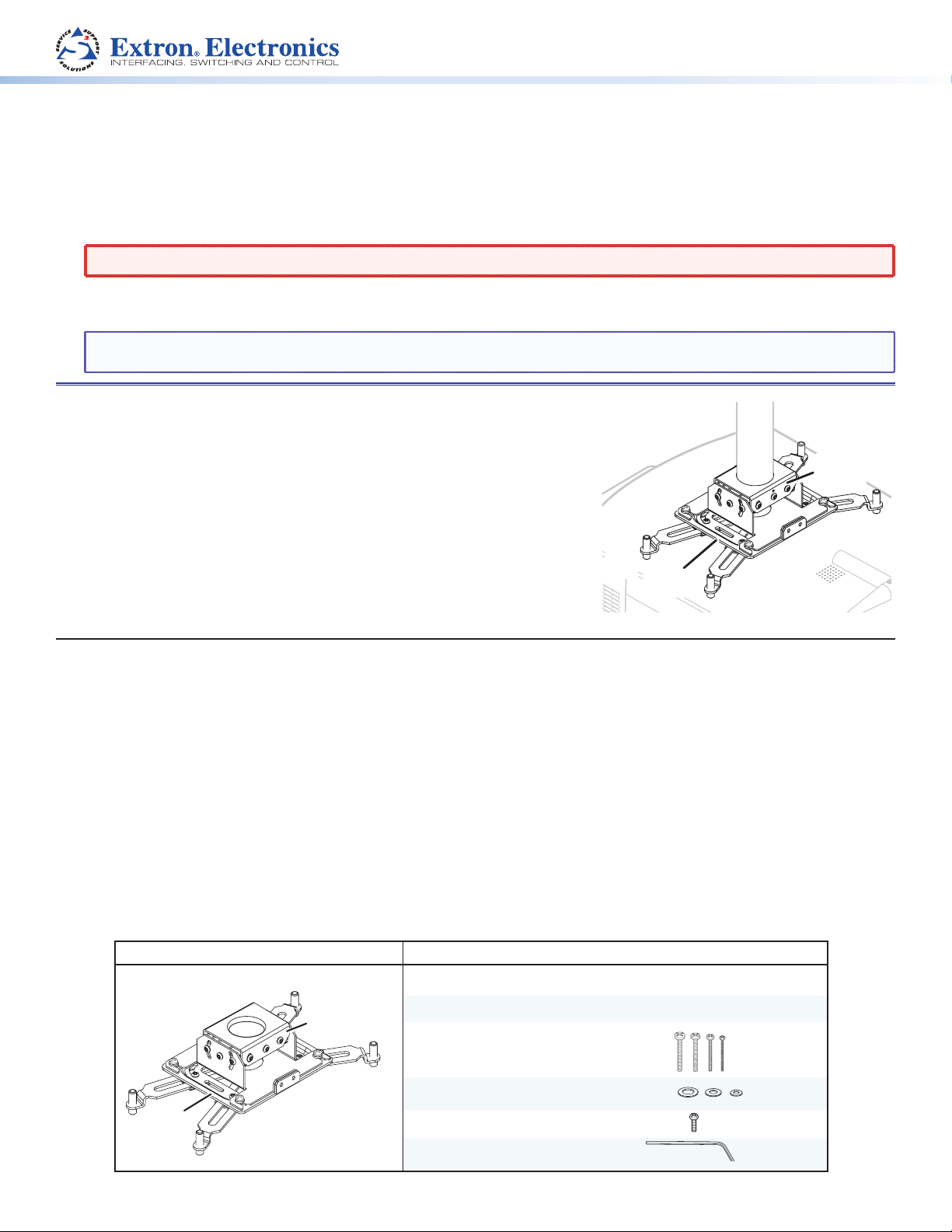
The UPB 25 is a versatile projector mount that works with most LCD/DLP
projectors weighing up to 25 pounds (11 kg) and accepts a 1.5-11.5 NPT/NPS
pipe. The flexibility of the UPB 25 allows for quick dismounting and
remounting of the projector to the support pipe.
The UPB 25 consists of two parts: the upper Adjuster Plate a, which mounts
onto the projector pipe, and the lower Projector Bracket b which attaches
directly to the projector. An assortment of mounting hardware is included.
a
Adjuster
Plate
PROPER MOUNTING PROCEDURES MUST BE
FOLLOWED.
Planning
Before starting the installation:
Check the Projector
c Weight — The UPB 25 can mount a projector with a maximum weight of 25 pounds (11 kg).
c Mounting point location — Use all available mounting points (typically 3 or 4) on the projector base to securely
attach the projector.
c Check the minimum and maximum throw distance of the projector. See the projector documentation for details.
Check the Mounting Location
It is important that you do the following:
c Check the structural ceiling to ensure that it can support a load four times the total weight of the final setup.
Included Parts
Part Qty. Part Qty.
UPB 25 1
Adjuster
Plate
Projector Bracket
Adjuster Plate
Mounting Screws (4 sets, 3-6 mm)
b
Projector
Bracket
1
1
16
Projector
Bracket
Washers (3 sets)
Adjustment Screws (10-32, ¾ inch)
Hex Wrench, 3/32 inch
12
4
1
1
Page 2
UPB 25 • Installation Guide (Continued)
Loosen the four locking
Clamp
Installing the UPB 25
Preparation
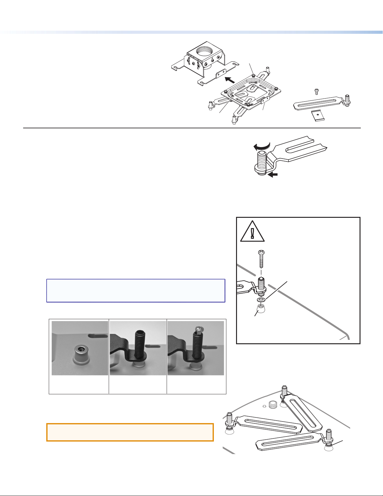
1. Separate the two main parts of the UPB 25
(see the figure at right).
2. Remove the four arm adjustment screws and
clamps from the Projector Bracket and remove
the arms.
Installing the Projector Bracket on the Projector
Follow the steps below to install the UPB 25. Some steps have accompanying
images for clarification, with the applicable step number indicated.
1. Invert the projector on a flat surface to access the mounting
points. Use a blanket or a similar item under the projector to
protect the projector and the surface.
2. On each arm, rotate the barrel (on the end of the arm) so that it only
just protrudes from the base of the arm (see the figure at right).
3. Select the correct sized mounting screws and the appropriately sized
washers that fit the projector mounting point inserts.
4. To attach the arms to the projector:
The next step (4a) is critical as it provides a flat surface for the
bracket to sit on, and must be done for each mounting point.
a. Place a washer on a mounting point (see the figure at right).
b. Position the arm so the barrel is over the washer.
c. Insert the mounting screw down through the barrel and washer,
and into the threaded insert. Lightly tighten the screw by hand.
NOTE: If using the 3- or 4-millimeter screws, place an additional
small washer under each screw head, on top of the
barrel, as well as one on the top of the mounting point.
Adjuster
Plate
Arm Adjustment
Screws (4)
screws and slide the
Adjuster Plate away from
the Projector Bracket.
Projector
Bracket
Security Flange
Arm
b
ATTENTION:
Place washer on
mounting point.
Adjustment
Screw
Barrel
Adjustment
Rotate the barrel
until it just protrudes
below the arm.
Ü
d. Repeat steps 4a through 4c for all projector mounting points.
4a 4b 4c
Place the washer Align the barrel Insert the screw
5. Pivot the arms so that they extend towards the center of the
projector (see the figure at right). Adjust the arms as needed
for your projector model.
ATTENTION: Potential Damage to Property. Avoid
overlapping the arms where possible.
2
Mounting Point
on Projector Base
This is critical as it provides a flat
surface for the bracket to sit on.
Washer
Page 3

⊗
6. With the security flange towards the rear of the projector, place the
Projector Bracket on top of the arms and adjust for slot alignment.
Using the slots on the bracket that are closest to the
barrel on each arm, place the clamp under the arm and lightly secure it
to the bracket with the adjustment screws (see the figure at right).
Loosely secure all the mounted arms.
NOTE: Where arms are unavoidably crossed, replace the
original adjustment screw with a supplied 10-32 ¾ inch
adjustment screw and secure both arms to the bracket
using one clamp. In addition, the barrels on the arms
must be raised to compensate, keeping the arms level
and reducing stress.
7. As close as possible, balance the weight of the projector evenly
across the Projector Bracket. Adjust the bracket on the arms as needed.
ATTENTION: Potential Damage to Property. Take into
consideration the uneven weight distribution of the
projector when lengthening or shortening the arms.
Distribute the projector weight evenly.
f
Using the slot closest
to the barrel, secure the
arms to the bracket with
the clamp and screw.
Lift the bracket at opposite corners to assess if the configuration is
approximately balanced.
The projector shown at right is as close as possible to being evenly
balanced.
8. Check for stress on the arms. To do this loosen the mounting screws
(do not remove). If the arm or the barrel lifts, this indicates stress on the
arm. Adjust the height of the threaded barrels to reduce or eliminate any
torque or stress that might be caused by crossed arms or by projector
mounting points with differing heights. It is important to keep the arms
level and as close (low) to the projector base as possible.
INCORRECT— Arm not level, CORRECT— Arm level,
causing stress on mounting point no stress on mounting point
Loosen the screw and adjust
h
the barrel height to reduce torque
on the arms and bracket.
i
Tighten down all the
mounting screws.
Washer
9. Check that the projector weight is still as evenly distributed as possible.
Hand tighten down the screws until snug.
ATTENTION: Potential Damage to Property. Do not overtighten
the mounting screws as this may damage the projector.
See the projector installation manual from the
manufacturer for the threaded insert torque setting
3
Page 4

UPB 25 • Installation Guide (Continued)
b
c
Attaching the Bracket to the Adjuster Plate
1. Using the hex wrench, back out the set screws on the
Adjuster Plate, and, keeping the plate level, screw it onto the
bottom of the pole (see the figure at right). A minimum of
three turns are needed to safely secure the bracket on the
pole.
Adjuster
Plate
Projector
Mounting
Pole
Lift Adjuster Plate up
a
to the projector pole
and screw into place.
Set Screws (2)
Security Flange
2. Secure the Adjuster Plate in position by tightening the set
screws down.
3. Carefully lift the projector up to the Adjuster Plate and, with
the security flanges at the rear, slide the Projector Bracket
onto the Adjuster Plate. Tighten the four Adjuster Plate
locking screws (see the figure at right).
Adjusting the Projector Alignment
Adjust the rotation (yaw)
Turn the unit on the projector pole to the correct position.
Secure the position by tightening the two set screws against the pole.
ATTENTION: Potential Damage to Property. Do not turn
the unit all the way to the end of the pole or the
projector may fall.
Adjust the vertical angle (pitch) and horizontal tilt (roll)
1. Loosen the pivot point screws, and the vertical and horizontal
adjustment screws.
Front
Adjuster Plate
Locking Screws (4)
Ya w/Rotation
Ver tical Angle
Adjustment
Screws (4)
Ver tical
Pivot Point
Screws (2)
Lift the bracket with the
b
projector attached, up to the
adjuster plate and slide into place.
Projector Bracket
Security Flange
(on rear)
a
Horizontal Angle
Adjustment Screws (4)
Set
Screws (2)
Horizontal
Pivot Point
Screws (2)
4
2. Adjust the vertical angle (pitch) of the projector to the correct
alignment, then tighten down the four vertical angle adjustment screws.
Pitch/Vertical Angle
3. Adjust the horizontal tilt (roll) of the projector to the correct
alignment. Tighten down the four horizontal angle adjustment screws.
4. When the projector is correctly aligned, tighten down all
Roll/Tilt
the remaining adjustment and pivot screws.
Securing the Projector Installation
The full installation can be secured by using a padlock through the two security flanges on the rear of the Projector Bracket
and Adjuster Plate.
Alternatively, you can use an Extron Security Screws Kit (part number 70-555-01, ordered separately).
Extron Headquarters
+1.800.633.9876 (Inside USA/Canada Only)
Extron Europe
+31.33.453.4040
© 2012 Extron Electronics — All rights reserved. All trademarks mentioned are the property of their respective owners. www.extron.com
Extron Asia
+65.6383.4400
Extron Japan
+81.3.3511.7655
Extron China
+86.21.3760.1568)
Extron Middle East
+971.4.2991800
Extron Korea
+82.2.3444.1571
Extron India
+91.80.3055.3777
68-1179-01
Rev. E
08 12
 Loading...