

Page 1

User Guide
TLP 350CV and TLE 350
TouchLink 3.5" Cable Cubby Touchpanel
and matching Cable Cubby Enclosure
TouchLink
®
68-1692-01 Rev. B
01 19
Page 2

Safety Instructions
Safety Instructions • English
WARNING: This symbol, , when used on the product, is intended to
alert the user of the presence of uninsulated dangerous voltage within the
product’s enclosure that may present a risk of electric shock.
ATTENTION: This symbol, , when used on the product, is intended
to alert the user of important operating and maintenance (servicing)
instructions in the literature provided with the equipment.
For information on safety guidelines, regulatory compliances, EMI/EMF
compatibility, accessibility, and related topics, see the Extron Safety and
Regulatory Compliance Guide, part number 68-290-01, on the Extron
website, www.extron.com.
Sicherheitsanweisungen • Deutsch
WARNUNG: Dieses Symbol auf dem Produkt soll den Benutzer darauf
aufmerksam machen, dass im Inneren des Gehäuses dieses Produktes
gefährliche Spannungen herrschen, die nicht isoliert sind und die einen
elektrischen Schlag verursachen können.
VORSICHT: Dieses Symbol auf dem Produkt soll dem Benutzer in
der im Lieferumfang enthaltenen Dokumentation besonders wichtige
Hinweise zur Bedienung und Wartung (Instandhaltung) geben.
Weitere Informationen über die Sicherheitsrichtlinien, Produkthandhabung,
EMI/EMF-Kompatibilität, Zugänglichkeit und verwandte Themen finden Sie
in den Extron-Richtlinien für Sicherheit und Handhabung (Artikelnummer
68-290-01) auf der Extron-Website, www.extron.com.
Instrucciones de seguridad • Español
ADVERTENCIA: Este símbolo, , cuando se utiliza en el producto,
avisa al usuario de la presencia de voltaje peligroso sin aislar dentro del
producto, lo que puede representar un riesgo de descarga eléctrica.
ATENCIÓN: Este símbolo, , cuando se utiliza en el producto, avisa
al usuario de la presencia de importantes instrucciones de uso y
mantenimiento recogidas en la documentación proporcionada con el
equipo.
Para obtener información sobre directrices de seguridad, cumplimiento
de normativas, compatibilidad electromagnética, accesibilidad y
temas relacionados, consulte la Guía de cumplimiento de normativas
y seguridad de Extron, referencia 68-290-01, en el sitio Web de Extron,
www.extron.com.
Instructions de sécurité • Français
AVERTISSEMENT : Ce pictogramme, , lorsqu’il est utilisé sur le
produit, signale à l’utilisateur la présence à l’intérieur du boîtier du
produit d’une tension électrique dangereuse susceptible de provoquer
un choc électrique.
ATTENTION : Ce pictogramme, , lorsqu’il est utilisé sur le produit,
signale à l’utilisateur des instructions d’utilisation ou de maintenance
importantes qui se trouvent dans la documentation fournie avec le
matériel.
Istruzioni di sicurezza • Italiano
AVVERTENZA: Il simbolo, , se usato sul prodotto, serve ad
avvertire l’utente della presenza di tensione non isolata pericolosa
all’interno del contenitore del prodotto che può costituire un rischio di
scosse elettriche.
ATTENTZIONE: Il simbolo, , se usato sul prodotto, serve ad avvertire
l’utente della presenza di importanti istruzioni di funzionamento e
manutenzione nella documentazione fornita con l’apparecchio.
Per informazioni su parametri di sicurezza, conformità alle normative,
compatibilità EMI/EMF, accessibilità e argomenti simili, fare riferimento
alla Guida alla conformità normativa e di sicurezza di Extron, cod. articolo
68-290-01, sul sito web di Extron, www.extron.com.
Instrukcje bezpieczeństwa • Polska
OSTRZEŻENIE: Ten symbol, , gdy używany na produkt, ma na celu
poinformować użytkownika o obecności izolowanego i niebezpiecznego
napięcia wewnątrz obudowy produktu, który może stanowić zagrożenie
porażenia prądem elektrycznym.
UWAGI: Ten symbol, , gdy używany na produkt, jest przeznaczony do
ostrzegania użytkownika ważne operacyjne oraz instrukcje konserwacji
(obsługi) w literaturze, wyposażone w sprzęt.
Informacji na temat wytycznych w sprawie bezpieczeństwa, regulacji
wzajemnej zgodności, zgodność EMI/EMF, dostępności i Tematy
pokrewne, zobacz Extron bezpieczeństwa i regulacyjnego zgodności
przewodnik, część numer 68-290-01, na stronie internetowej Extron, www.
extron.com.
Инструкция по технике безопасности • Русский
ПРЕДУПРЕЖДЕНИЕ: Данный символ, , если указан
на продукте, предупреждает пользователя о наличии
неизолированного опасного напряжения внутри корпуса
продукта, которое может привести к поражению
электрическим током.
ВНИМАНИЕ: Данный символ, , если указан на продукте,
предупреждает пользователя о наличии важных инструкций
по эксплуатации и обслуживанию в руководстве,
прилагаемом к данному оборудованию.
Для получения информации о правилах техники безопасности,
соблюдении нормативных требований, электромагнитной
совместимости (ЭМП/ЭДС), возможности доступа и других
вопросах см. руководство по безопасности и соблюдению
нормативных требований Extron на сайте Extron: ,
www.extron.com, номер по каталогу - 68-290-01.
安全说明 • 简体中文
警告: 产品上的这个标志意在警告用户该产品机壳内有暴露的危险 电压,
有触电危险。
注意: 产品上的这个标志意在提示用户设备随附的用户手册中有
重要的操作和维护(维修)说明。
Pour en savoir plus sur les règles de sécurité, la conformité à la
réglementation, la compatibilité EMI/EMF, l’accessibilité, et autres sujets
connexes, lisez les informations de sécurité et de conformité Extron, réf.
68-290-01, sur le site Extron, www.extron.com.
关于我们产品的安全指南、遵循的规范、EMI/EMF 的兼容性、无障碍
使用的特性等相关内容,敬请访问 Extron 网站 , www.extron.com,参见
Extron 安全规范指南,产品编号 68-290-01。
Page 3

安全記事 • 繁體中文
警告: 若產品上使用此符號,是為了提醒使 用者,產品機殼內存在著
可能會導致觸電之風險的未絕緣危險電壓。
注意 若產品上使用此符號,是為了提醒使用者,設備隨附的用戶手冊中有
重 要 的 操 作 和 維 護( 維 修 )説 明 。
有關安全性指導方針、法規遵守、E MI/EMF 相容性、存取範圍和相關主題的詳細
資訊,請瀏覽 Extron 網站:www.extron.com,然後參閱《Extron 安全性與
法規遵守手冊》,準則編號 68-290-01。
安全上のご注意 • 日本語
警告: この記 号 が製品上に表示されている場合は、筐体内に絶縁されて
いない高電圧が流れ、感電の危険があることを示しています。
注意:この記号 が製品上に表示されている場合は、本機の取扱説明書に
記載されている重要な操作と保守( 整備)の 指示についてユーザーの注 意
を喚起するものです。
安全上のご注意、法規厳守、EMI/EMF適合性、その他の関連項目に
つ い て は 、エ ク ストロ ン の ウ ェブ サ イト www.extron.com よ り 『 Extron Safety
and Regulatory Compliance Guide』 ( P/N 68-290-01) をご覧ください。
안전 지침 • 한국어
경고: 이 기호 가 제품에 사용될 경우, 제품의 인클로저 내에 있는
접지되지 않은 위험한 전류로 인해 사용자가 감전될 위험이 있음을
경고합니다.
주의: 이 기호 가 제품에 사용될 경우, 장비와 함께 제공된 책자에 나와
있는 주요 운영 및 유지보수(정비) 지침을 경고합니다.
안전 가이드라인, 규제 준수, EMI/EMF 호환성, 접근성, 그리고 관련 항목에 대한
자세한 내용은 Extron 웹 사이트(www.extron.com)의 Extron 안전 및 규제 준수
안내서, 68-290-01 조항을 참조하십시오.
Copyright
© 2009 - 2019 Extron Electronics. All rights reserved.
Trademarks
All trademarks mentioned in this guide are the properties of their respective owners.
The following registered trademarks®, registered service marks(SM), and trademarks(TM) are the property of RGBSystems, Inc. or
Extron Electronics (see the current list of trademarks on the Terms of Use page at www.extron.com):
Registered Trademarks
(®)
Cable Cubby, ControlScript, CrossPoint, DTP, eBUS, EDID Manager, EDID Minder, Extron, Flat Field, FlexOS, Glitch Free, Global Configurator,
Global Scripter, GlobalViewer, Hideaway, HyperLane, IPIntercom, IPLink, Key Minder, LinkLicense, LockIt, MediaLink, MediaPort,
NetPA, PlenumVault, PoleVault, PowerCage, PURE3, Quantum, Show Me, SoundField, SpeedMount, SpeedSwitch, StudioStation,
SystemINTEGRATOR, TeamWork, TouchLink, V-Lock, VideoLounge, VN-Matrix, VoiceLift, WallVault, WindoWall, XTP, XTP Systems, and ZipClip
Registered Service Mark
(SM)
: S3 Service Support Solutions
Trademarks (™
)
AAP, AFL (Accu-Rate Frame Lock), ADSP (Advanced Digital Sync Processing), Auto-Image, AVEdge, CableCover, CDRS (Class D
Ripple Suppression), Codec Connect, DDSP (Digital Display Sync Processing), DMI (Dynamic Motion Interpolation), DriverConfigurator,
DSPConfigurator, DSVP (Digital Sync Validation Processing), eLink, EQIP, Everlast, FastBite, FOX, FOXBOX, IP Intercom HelpDesk, MAAP,
MicroDigital, Opti-Torque, PendantConnect, ProDSP, QS-FPC (QuickSwitch Front Panel Controller), Room Agent, Scope-Trigger, ShareLink, SIS,
Simple Instruction Set, Skew-Free, SpeedNav, Triple-Action Switching, True4K, Vector™ 4K, WebShare, XTRA, and ZipCaddy
Page 4

FCC Class A Notice
This equipment has been tested and found to comply with the limits for a Class A digital
device, pursuant to part15 of the FCC rules. The ClassA limits provide reasonable protection
against harmful interference when the equipment is operated in a commercial environment.
This equipment generates, uses, and can radiate radio frequency energy and, if not installed
and used in accordance with the instruction manual, may cause harmful interference to radio
communications. Operation of this equipment in a residential area is likely to cause interference.
This interference must be corrected at the expense of the user.
NOTE:
Battery Notice
This product contains a battery. Do not open the unit to replace the battery. If the
battery needs replacing, return the entire unit to Extron (for the correct address, see the Extron
Warranty section on the last page of this guide).
CAUTION: Risk of Explosion if Battery is replaced by an Incorrect Type. Dispose of Used
Batteries According to the Instructions.
ATTENTION : Risque d’explosion. Ne pas remplacer la pile par le mauvais type de pile.
Débarrassez-vous des piles utilisées selon le mode d’emploi.
• This unit was tested with shielded I/O cables on the peripheral devices. Shielded
cables must be used to ensure compliance with FCC emissions limits.
• For more information on safety guidelines, regulatory compliances, EMI/EMF
compatibility, accessibility, and related topics, see the Extron Safety and
Regulatory Compliance Guide on the Extron website.
Page 5

Conventions Used in this Guide
Notifications
In this user guide, the following are used:
WARNING: Potential risk of severe injury or death.
AVERTISSEMENT : Risque potentiel de blessure grave ou de mort.
CAUTION: Risk of minor personal injury.
ATTENTION : Risque de blessuremineure.
ATTENTION:
• Risk of property damage.
• Risque de dommages matériels.
NOTE: A note draws attention to important information.
Software Commands
Commands are written in the fonts shown here:
^AR Merge Scene,,Op1 scene 1,1 ^B 51 ^W^C
[01] R 0004 00300 00400 00800 00600 [02] 35 [17] [03]
E X!*X1&*X2)*X2#*X2!
CE
}
NOTE: For commands and examples of computer or device responses mentioned
in this guide, the character “0” is used for the number zero and “O” represents the
capital letter “o”.
Computer responses and directory paths that do not have variables are written in the font shown
here:
Reply from 208.132.180.48: bytes=32 times=2ms TTL=32
C:\Program Files\Extron
Variables are written in slanted form as shown here:
ping xxx.xxx.xxx.xxx —t
SOH R Data STX Command ETB ETX
Selectable items, such as menu names, menu options, buttons, tabs, and field names are written
in the font shown here:
From the File menu, select New.
Click the OK button.
Specifications Availability
Product specifications are available on the Extron website, www.extron.com.
Extron Glossary of Terms
A glossary of terms is available at www.extron.com/technology/glossary.aspx.
Page 6

Page 7

Contents
Introduction............................................................ 1
About this Guide .....................................................1
About the TLP 350CV ............................................. 1
About the TLE 350 .................................................. 2
Features ..................................................................2
TLP 350CV .........................................................2
TLE 350 .............................................................. 2
Requirements for the TLP 350CV ............................3
Software .............................................................3
Hardware ............................................................3
Application Diagram ................................................ 3
Installation Overview ........................................... 4
Mounting ................................................................. 6
Planning .................................................................. 6
Tools Required for Installation .................................. 7
Included Parts ......................................................... 7
Ensure Adequate Under-table Clearance for
Retractors .............................................................. 8
Cutting the Table ..................................................... 8
Cut-out Dimensions ............................................8
Cutting the Surface ............................................. 8
Running Cables ....................................................10
Installing Cable Retractors (Optional) ..................... 10
Installing Power Modules (Optional) ....................... 11
Preparing and Installing the AAP Assemblies .........12
Installing AAPs ..................................................12
Inserting the AAP Assemblies ............................ 13
Mounting the Enclosure.........................................14
Bottom Panel Features (TLP 350CV only) ..............15
Power on the TLP 350CV .................................16
Front Panel Features ......................................... 17
Front Panel Features .............................................17
On-screen Menus ............................................... 19
Setup Menu ..........................................................19
Main..................................................................19
Volume ..............................................................20
Time .................................................................21
IP ...................................................................... 21
Video ................................................................23
Calibration Screen .................................................24
Configuration Software ..................................... 25
Configuration and Control Software ......................25
Installing Software .................................................26
GUI Configurator and Global Configurator
Installation ........................................................ 26
Using the TouchLink Panel Web Pages ................. 27
GUI Design and Configuration ............................... 29
Using GUI Configurator ..................................... 29
Using Global Configurator ................................. 33
Reference Material ............................................. 38
Reset Modes.........................................................38
Use Factory Firmware .......................................38
Run or Stop Events ........................................... 39
Reset All IP Settings .......................................... 39
Reset to Factory Defaults .................................. 39
Updating Firmware ................................................40
Obtaining the Latest Firmware File ....................40
Updating Firmware Using Firmware Loader .......42
Updating Firmware Using GUI Configurator .......43
Updating Firmware Using the Touchpanel
Web Pages ......................................................43
Button Kits and Replacement ................................44
Button Kits ........................................................ 44
Button Replacement .........................................44
TLP 350CV and TLE 350 • Contents vii
Page 8

TLP 350CV and TLE 350 • Contents viii
Page 9

Introduction
The touchpanels are ideal for any AV applications requiring medium or large touchpanels with
flexible mounting options and fully customizable interfaces.
This section provides an overview of these products:
• About this Guide
• About the TLP 350CV
• About the TLE 350
• Features
• Requirements for the TLP 350CV
• Application Diagram
About this Guide
This guide describes the function, installation of both the Extron TLP350CV Cable Cubby
TouchLink touchpanel and the matching Extron TLE 350 Cable Cubby enclosure and operation
of the TLP350CV.
Unless otherwise stated, the terms “touchpanel,” “TLP,” or “TLP350CV” refer to the TLP 350CV.
The terms “TLE” or “TLE350” refer to the TLE350. The term “enclosure” refers to either product.
NOTES:
• The first part of this guide (pages 1-14) describes the procedure for installing the
• The second part of the guide (from page 15 onwards) describes the touchpanel and
About the TLP 350CV
The Extron TLP 350CV TouchLink 3.5 inch Cable Cubby Touchpanel combines AV system
control with cable management. It features a tilt-up, full-color touchscreen in an elegant, metal
enclosure that can be mounted securely into a tabletop, lectern or other flat surface.
In addition, ten customizable backlit buttons provide expanded control capabilities to ensure that
critical functions are easily accessible. The TLP 350CV touchpanel enables integrators to deploy
a fully configurable furniture-mounted touchscreen control with cable management and easy
access to AV connectivity and power.
Global Configurator and GUI Configurator software, along with ready-to-use templates, make
system setup fast and easy, with no programming required. An integrated Ethernet port provides
communication with IP Link-enabled control processors for controlling and monitoring AV
equipment such as projectors, displays, switchers, and source devices over a standard Ethernet
network.
AV connectivity and cable management is provided by convenient pullout cables such as VGA,
3.5 mm audio, AV, network, HDMI, DVI and Display port cables. Passive AAP plates and a dual
AC outlet are also available. Using the video input, the panel can monitor video source devices
whether as a preview aid or a personal viewer for the operator.
cable cubby enclosure and refers to both the TLP 350CV and the TLE 350.
refers only to the TLP 350CV.
TLP 350CV and TLE 350 • Introduction 1
Page 10

About the TLE 350
Features
TLP 350CV
The Extron TLE 350 Cable Cubby is a furniture-mountable enclosure that provides easy access
to AV, data, and power connections. It has a low-profile design with flip-up lid and nine singlespace AAP openings that can be populated with Extron AAPs and Retractors. The dimensions
are identical to the TLP 350CV, making it an ideal, complementary solution for these touchpanels.
• 3.5 inch flip-up color touchscreen — with 320x240 resolution and 18-bit color depth.
• Ten customizable backlit buttons — can be assigned functions with Extron Global
Configurator.
NOTE: Use GUIConfigurator (version 1.3 or later) and Global Configurator (version 3.3
or later) to configure the TLP 350CV touchpanel. Do not use GUI Designer or Global
Configurator Plus and Professional.
• Full-motion video display — for preview and monitoring
• Compatible with all IP Link controllers
NOTE: The TLP 350CV is not compatible with IPLink Pro or IPCP Pro controllers.
• Built-in speaker — provides audio for video preview and audible feedback from button
presses.
• Light sensor — adjusts screen brightness as the ambient room lighting changes.
• AV connectivity options:
• Holds up to 9 single-space AAP-Architectural Adapter Plates
• Holds up to 6 Retractor Cable Retraction Systems
• Cable Cubby design — offers easy access to AV, data, and power connections.
• AC power modules available for US, Europe, and other major world markets.
• Convenient LED lighting — illuminates power and AV Cable Cubby area.
• Integrated lid switch — automatically wakes the touchpanel when opened and can trigger
any other system function.
• Fully configurable — using Extron GUI Configurator and Global Configurator.
• Supports the Extron Control App.
TLE 350
• Dimensions are identical to the TLP 350CV — makes it an ideal, complementary
solution for this touchpanel.
• Furniture-mountable enclosure — provides easy access to AV, data, and power
connections.
• Low profile design — with flip-up lid.
• Nine single-space AAP openings — can be populated with Extron AAPs and Retractors.
• AC power modules available for US, Europe, and other major world markets.
TLP 350CV and TLE 350 • Introduction 2
Page 11

Requirements for the TLP 350CV
UNSWITCHED
100-240V/ 5A MAX
UNSWITCHED
100-240V/ 5A MAX
UNSWITCHED
100-240V/ 5A MAX
UNSWITCHED
100-240V/ 5A MAX
Software
NOTE: You must use GUIConfigurator (version 1.3 or later) and Global Configurator (version
3.3 or later) to configure the TLP 350CV. Do not use GUI Designer or Global Configurator
Plus and Professional.
For a complete list of the requirements to run GUI Configurator or Global Configurator 3, see
product page at www.extron.com for the appropriate software.
Hardware
An Extron IP Link controller must also be connected to the same network domain as the
TouchLink panel. See the TLP 350CV product page at www.extron.com for suitable products.
NOTE: The TLP 350CV is not compatible with Extron IP Link Pro controllers.
Application Diagram
Extron
TLE 35 0
3.5" TouchLink
Enclosure
Extron
TLP 350CV
3.5" TouchLink
Touchpanel
Cable Cubby
DISPLAY ON
LAPTOP
DISPLAY OFF
PC
MUTE
DVD
VOLUME
DVD
VOLUME
DOC CAM
AUXILIARY
Video
Extron
<< More
Extron
TLP 350CV
3.5" Cable Cub by
TouchLink
Touchpanel
Figure 1. Application Diagram
TLP 350CV and TLE 350 • Introduction 3
Page 12

Installation Overview
Follow all these steps to mount and install the TLP 350CV. Follow steps 3 and 4 to mount the
TLE 350:
1. Before starting, download and install the latest versions of the following software:
GUI Configurator — for designing layouts for Extron TouchLink touchpanels.
Global Configurator — for setting up and configuring the control processor and
touchpanel.
See Configuration Software on page 25.
2. Obtain the following network information from your network administrator:
DHCP status (On or Off). If DHCP is off, you also require
IP address
Subnet mask
Gateway
User name — this can be either admin or user.
Password — by default this is extron (for either admin or user).
MAC address — make a note of the touchpanel MAC address.
3. Prepare to mount the CableCubby:
Make sure you are familiar with all the Included Parts (see page 7) and have all the
Tools Required for Installation (see page 7) for installing the cable cubby.
Plan where you are going to install the Cable Cubby and how you are going to cut the
hole.
Ensure the TLP 350CV is oriented correctly and that there is adequate room for cables
and cable retractors (optional).
Ensure you are using the correct cut-out template or dimensions (see Cut-out
Dimensions on page 8).
Ensure the installation complies with all necessary regulations.
4. Mount the Cable Cubby:
Cut the table surface (see Cutting the Table on page 8).
Run all cables to the unit (see Running Cables on page 10).
Install cable retractors (see Installing Cable Retractors (Optional) on page 10).
Install the power module (see Installing Power Modules (Optional) on page 11).
Put together and install the AAP assembly (see Preparing and Installing the AAP
Assemblies on page 12).
Mount the Cable Cubby (see Mounting the Enclosure on page14).
TLP 350CV and TLE 350 • Installation Overview 4
Page 13

5. Connect cables to the touchpanel. The unit is powered by a 12 VDC power supply.
Connect the power supply (see 12 VDC External Power Supply on page 15).
ATTENTION:
• Do not power on the touchpanels or control processors until you have read the
Attention notice on page 15.
• Ne branchez pas les écrans tactiles ou les contrôleurs avant d’avoir lu les mises
en garde page15.
6. Set up the TLP 350CV for Network Communication:
Connect the PC that you are using for the setup, the control processor, and the
touchpanel to the same Ethernet subnetwork.
Use the Setup Menu (see page 19) or Global Configurator to set the DHCP status
and, if necessary, the IP address, subnet mask, gateway, and related settings for the
touchpanel.
Configure the TLP 350CV — the GUI Configurator Help File and the Global Configurator
Help File provide step-by-step instructions and detailed information.
The Global Configurator Help File also includes an introduction to that software and
sections on how to start a project and configuration.
TLP 350CV and TLE 350 • Installation Overview 5
Page 14

Mounting
This section describes how to mount the TLP 350CV Cable Cubby enclosure. The TLE 350 is
installed in exactly the same way. The section covers covers:
• Planning
• Tools Required for Installation
• Included Parts
• Ensure Adequate Under-table Clearance for Retractors
• Cutting the Table
• Running Cables
• Installing Cable Retractors (Optional)
• Installing Power Modules (Optional)
• Preparing and Installing the AAP Assemblies
• Mounting the Enclosure
• Bottom Panel Features (TLP 350CV only)
Planning
1. Before making any cuts, select the best location for the enclosure.
2. Verify that you have the correct template or Cut-out Dimensions (see page 8).
3. Decide on the method for cutting a hole in the table (see Cutting the Table on page 8).
There are three methods available:
Ensure that the edge that opens on the lid is oriented correctly.
Ensure there is enough space for all the system cables and components, above and
below the table. Take account of:
• Clearances for under-table cabling, especially if the cable has a large bend radius.
• Ensure Adequate Under-table Clearance for Retractors if they are to be
installed (see page 8).
• The number and type of AAPs required for the installation.
• The location of devices that connect to the AAPs either above or below the table.
• Router with routing template — requires a router template, which must be
purchased separately.
• CNC router — must be programmed with the correct dimensions.
• Reciprocating saw or jigsaw — requires a paper template (available at
www.extron.com).
The hand router used with the routing template or the CNC wood router are the most
accurate methods for cutting the hole. Either one of these methods is recommended by
Extron. The jigsaw is less accurate, but is also acceptable.
4. Check all relevant regulations.
Ensure that the installation complies with local, state, and national building and electrical
codes.
Ensure that the installation complies with the Americans with Disabilities Act or other
accessibility requirements.
TLP 350CV and TLE 350 • Mounting 6
Page 15
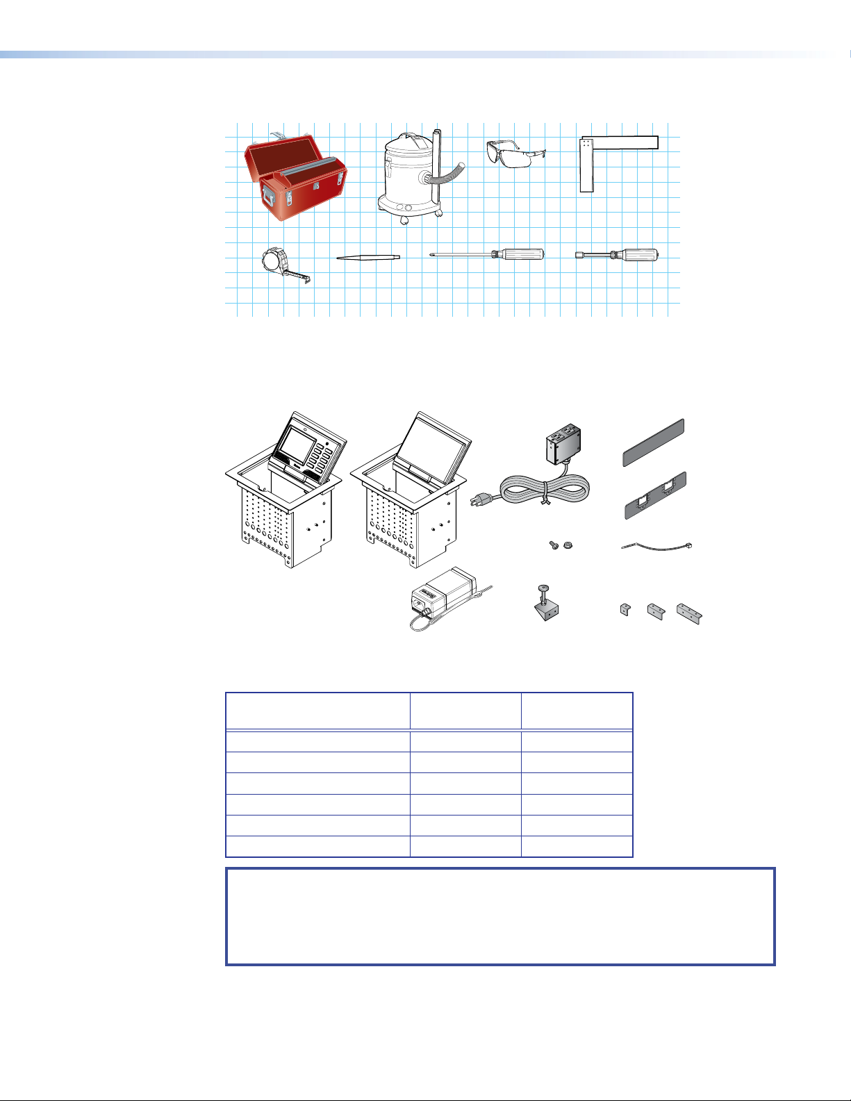
Tools Required for Installation
AAP Shelf Bracket Kits
Square
Safety Glasses
Vacuum Cleaner
Included Parts
Marking Pen
Tape Measure
Phillips Screw Driver
1/4" Hex Nut Driver
Figure 2. Tools Required for Installaton
Open the shipping container and verify that all the following components are present:
Blank AAPs
TLP 350CV or TLE 350
12 VDC, 1.5 A
Power Supply
AC Power Module*
#4−40 Screws
and Nuts
1A MAX
100-240V 50-60Hz
Table Clamps
Pass-thru AAPs
Zip Ties
(2 brackets/kit)
2 Pos
3 Pos1 Pos
* The unit may be provided without a power module or with a different power module (see the
table below).
AC Power Module
*
Pass-through AAPs†
Blank AAPs
1-position Bracket Kit
2-position Bracket Kit
3-position Bracket Kit
With Power
Module
1 0
4 4
3 5
4
0 0
2 3
1 1
Without Power
Module
NOTES:
* Inside the US, the TLP 350CV may be purchased with or without an AC power module. If a
power module is required for the TLE 350, it must be purchased separately.
Outside the US, see www.extron.com to purchase an AC power module that is suitable for
your location.
† Active or Passive AAPs must be purchased separately (see www.extron.com).
Figure 3. Parts Included with the TLP 350CV and TLE 350
TLP 350CV and TLE 350 • Mounting 7
Page 16

Ensure Adequate Under-table Clearance for Retractors
Horizontal Mounting Clearance
Vertical Mounting Clearance
2.7" (6.9 cm)
2.7" (6.9 cm)
Retractors are optional accessories for handling cables with the TLP 350CV. If you are using
retractors, ensure that there is sufficient room beneath the table to accommodate them.
Horizontal mounting provides maximum legroom and protects the retractors from accidental
damage. Vertical mounting is used if space or access makes horizontal mounting difficult. To
satisfy ADA compliance requirements, there is also an option to mount the retractors at a 30°
angle (see the Retractors User Guide, which is available at www.extron.com).
9.8"
(24.9 cm)
3.0"
17.0"
(43.3 cm)
(7.6 cm)
24.1"
(61.2 cm)
30.1"
(76.5 cm)
Figure 4. Under-table Clearance Requirements for Retractors
Cutting the Table
Cut-out Dimensions
Cutting the Surface
9.8"
(24.9 cm)
XL Models
23.0" (58.5 cm)
3.0"
(7.6 cm)
XL Models
There are three alternative methods of making the hole for the TLP 350CV (see Cutting the
Surface below):
• If using a Router with routing template, you should purchase the TLP 350CV routing
template.
• If using a CNC router, use the exact cut-out dimensions.
• If using a Reciprocating saw or jigsaw use the paper cut-out template.
WARNING: Wear safety glasses when operating power equipment. Failure to comply can
result in eye injury.
AVERTISSEMENT : Portez des lunettes de sécurité lorsque vous utilisez l’équipement
électrique. Ne pas respecter cela peut conduire à une blessure à l’oeil.
TLP 350CV and TLE 350 • Mounting 8
Page 17

ATTENTION:
P/N
P/
• The opening in the table for the Cable Cubby should be cut only by licensed and
bonded craftspeople. Exercise care to prevent scarring or damaging the furniture.
• L’ouverture dans la table pour le CableCubby devrait être coupée seulement par
des artisans autorisés et qualifiés. Faites attention à ne pas faire de marques sur le
meuble et à ne pas l’endommager.
• Use the appropriate metal Extron routing template or refer to the surface cutout
dimensions before cutting a hole in the furniture or other surface. Pay special
attention to the direction the unit will face. The connector access side is underlined
(see CNC Router below). Extron is not responsible for miscut mounting holes.
• Utilisez le gabarit de détourage métallique approprié ou reportez-vous aux
dimensions de découpe de la surface indiquées ci-après avant de découper
le meuble ou la surface. Faites particulièrement attention à la directions dans
laquelle l’unité sera dirigée. Le côté pour accéder au connecteurs est souligné (voir
CNCRouter ci-dessous). Extron ne sera pas responsable des erreurs de coupe.
• The surfaces of the Cable Cubby enclosure have screws and other protrusions that
could damage fine furniture. Do not rest the enclosure on unprotected furniture.
• La surface du boîtier Cable Cubby a des vis et d’autres éléments en saillie qui
pourrait endommager des meubles fins. N’appuyez pas le boîtier sur du moblier
non protégé.
• Ensure the table surface is at least 0.375 inches (0.95 cm) thick.
• Assurez vous que la surface de la table est au moins 0,95 cm (0,375”) d’épaisseur.
Be certain the cut is laid out in exactly the desired location and the edge that opens on the lid
is correctly oriented. After verifying and checking dimensions, cut a hole in the surface of the
furniture where the enclosure is being installed.
Router with routing template
If using a routing template, make sure it is
the correct template for the TLP350CV (see
CABLE CUBBY 300
www.extron.com). For complete instructions,
see the RoutingTemplateUserGuide,
available at www.extron.com.
NOTE: The metal router guide must be
HSA 200
USER ACCESS
HSA 200
CABLE CUBBY 300
USER ACCESS
purchased separately. It is reusable
and should not be discarded when the
installation is complete.
CNC router
If using a CNC router, enter the correct dimensions for the TLP350CV:
7.50 +0.00/-0.02 inches W x 6.00 +0.00/-0.02 inches D
19.05 +0.00/-0.05 cm W x 15.24 +0.00/-0.05 cm D
NOTE: The width dimension (underlined)
refers to the side with AAP access.
Reciprocating saw or jigsaw
If using a reciprocating saw or jigsaw, make sure to
use the paper cutout template for the TLP350CV.
The template is available at www.extron.com.
2. Remove the surface cut-out area
1. Confirm the product to be installed.
Do not shrink.
Print scale 1:1
Page size: 11" x 17"
P/N 68-2046-01 Rev. B
(Do not cut this line.)
Outer Edge of Trim Ring
4. Cut the opening.
is being installed.
furniture where the TLP 710MV
3. Mark the position on the wall or
(gray) from the template.
TLP 710CV
Cut-Out Template for the Extron
TLP 350CV and TLE 350 • Mounting 9
Page 18

Running Cables
e the bolt
Insert the bolt thr
r
the side of the Cable Cubby
and r
Run all cables necessary to support the AC connector, the cables stored in the cubby, and all
planned AAP connectors. Run the cables below the table and through the hole that was cut in
the previous step (Cutting the Surface). Leave enough slack in the cables to connect or route
them before the cubby is installed in the table. Leave enough slack for the external power supply
and to connect AV cables and the cable for PoE and LAN to the TLP350CV.
Installing Cable Retractors (Optional)
Extron cable retractors retract and store extended cables in Cable Cubby systems, preventing
them from tangling underneath the table. Retractor kits are available for several cable types. Up
to six retractors can be installed in the TLP350CV enclosure (three at either end). They are not
provided with the TLP350CV and must be purchased separately.
The buttons on the retractors must be placed at one end of the unit and must, therefore, be the
first or the last items added.
Secur
3
with the nut.
2
etractor mounting hole on
etractor assembly.
ough the
Insert retractors into the
1
touchpanel enclosure
from underneath.
4
Secure the locking screw
on each retractor.
Do not overtighten.
Figure 5. Installing Cable Retractors
To mount the retractors horizontally and for further information and installation instructions,
see the Retractors User Guide, which is available at www.extron.com. The guide also
provides information about mounting the retractors at a 30° angle to satisfy ADA compliance
requirements.
TLP 350CV and TLE 350 • Mounting 10
Page 19

Installing Power Modules (Optional)
Secure the po
to the
with #4-40 Phillips head
scre
WARNING:
AVERTISSEMENT :
• Switch off all electrical power before connecting the AC conduit to a junction box, and
keep power off until installation is complete.
• Débranchez toutes les sources d’alimentation électrique avant de connecter le
conduit d’alimentation à un boîtier d’encastrement, et gardez l’alimentation éteinte
jusqu’à ce que l’installation soit complète.
• If the power cable is installed next to the retractors, ensure the power cable cannot
get tangled in the cable retractor mechanism.
• Si le câble d’alimentation est installé à côté des rétracteurs, assurez vous qu’il ne
puisse pas s’emmêler dans le mécanisme du rétracteur de câbles.
ATTENTION:
• All electrical installation must be performed by qualified personnel in accordance with
local and national building codes and electrical codes.
• Toute installation électrique, doit être effectuée par un personnel qualifié,
conformément aux codes du bâtiment, aux codes incendie et sécurité, et aux codes
électriques, locaux et nationaux.
NOTE: Different countries require different power adapters. See www.extron.com to select
a power module that is suitable for your location.
The power module takes up two or three AAP spaces and may be installed before or after the
AAP assembly is installed or, if desired, with AAPs on either side.
wer module
TLP 350CV frame
ws and star washers.
Figure 6. Installing a Power Module in the TLP 350CV
1. Secure the power module with at least two #4-40 Phillips head screws and star washers.
CAUTION: Risk of electric shock: To ensure proper electrical grounding, use the
provided grounding screws and star washers.
ATTENTION : Risque de choc électrique: Afin d’assurer une mise à la terre correcte,
utilisez les fixations de mise à la terre et les rondelles en étoile fournies.
2. Run the cable or conduit to a convenient junction box. Extron recommends the circuit be
attached to a junction box that is directly wired to the main circuit.
TLP 350CV and TLE 350 • Mounting 11
Page 20

Preparing and Installing the AAP Assemblies
ts
Front Brackets
The extra column of
mounting points is fo
installing single-space
AAP brackets.
The AAP assembly organizes the AAPs onto a frame that can easily be inserted or removed from
the TLP350CV enclosure. Pass-through and blank AAP plates are provided with the TLP350CV.
Active or passive AAPs must be purchased separately. For the complete range of available AAPs,
see www.extron.com.
If neither power modules nor cable retractors are installed, up to 9 AAPs can be accommodated.
Cable retractors, if installed, occupy the space of two AAP slots. The power modules occupy the
space of two (US) or three (European or Universal) AAP slots.
AAP brackets are available in one-space, two-space, and three-space configurations. Decide the
location of each AAP prior to assembly. Pass-through AAPs provide direct cable connection and
the cable must be installed as they are being mounted on the brackets.
TIP: The recommended way to install the cables and AAPs is to populate the brackets
with AAP plates outside the enclosure as shown in Installing AAPs below, then install
the populated AAP assemblies into the enclosure, as shown in Inserting the AAP
Assemblies on the following page.
NOTE: An extra column of AAP bracket mounting points is available
for use with TLP single-space AAP mounting brackets (see the
illustration to the right). Single-space brackets do not fit in any other
location.
r
Figure 7. Preparing the AAP Assembly
Installing AAPs
1. Determine how many AAPs are being used and how many front and rear brackets are
2. Place the AAP onto the bracket. Ensure one end of the AAP is secured to a front bracket
Rear Bracke
needed. The brackets come in one-space, two-space, and three-space configurations. The
rear brackets are taller than the front brackets.
and the other end is secured to a rear bracket. Whenever possible match the width of the
front and rear brackets.
NOTES:
• Active, passive and pass-through AAPs can be mixed.
• Cables can be attached to the active or passive AAPs after assembly.
• Insert cables into each pass-through AAP before the next AAP is added.
TLP 350CV and TLE 350 • Mounting 12
Page 21

3. Attach the AAP loosely to the bracket with the supplied #4-40 captive washer nuts.
Phillips Head Scre
(secure AAP
assemb
ly through
NOTE: At this time, captive washer nuts should be hand tightened; otherwise it is
difficult to attach the brackets to the frame of the TLP 350CV (see Inserting the AAP
Assemblies below).
When using pass-through AAPs, ensure that the opening in the grommet is accessible for
inserting cables, if required.
4. Insert one cable through the opening of each grommet. Cables can only be inserted into the
pass-through AAP while the front edge is exposed. Securing the next AAP in place closes
the opening on the previous AAP and ensures that the cable cannot escape.
5. Add AAPs until the bracket is filled. Spaces that are not required can be filled with blank
AAPs.
Inserting the AAP Assemblies
ws
ly)
2
2
Large holes
provide tool
access to fasten
rear brackets.
Push assemb
11
AUDIO
UTER
COMP
bottom of enclosure.
Tighten down
3
3
AAP nuts.
Figure 8. Inserting the AAP Assemblies
1. Push the first AAP assembly through the bottom of the enclosure (1).
Align the holes in the rear bracket the bottom row of holes on the rear face of the enclosure
and, if necessary, pull any pass-through cables out of the way.
2. Insert a long screwdriver through the large slot in the front panel to secure the rear bracket
to the rear face of the enclosure with the provided #4-40 Phillips head screws (2).
3. Secure the front bracket to the front face of the enclosure, using the provided #4-40 Phillips
head screws.
4. Use a hex nut wrench to tighten the AAP captive washer nuts (3).
5. Repeat steps 1 through 4 to add each AAP assembly.
6. Run cables to connect the source and output devices to the active and passive AAPs.
TLP 350CV and TLE 350 • Mounting 13
Page 22

Mounting the Enclosure
Mount the cable cubby enclosure in the table.
CAUTION: The flanged edges of the top of the surface enclosure are sharp. These edges
are also soft and may be easily nicked or bent. Exercise caution when handling the
enclosure to prevent personal injury or damage to the enclosure.
ATTENTION : Les extrémités à brides du haut de la surface du boîtier sont aiguisées. Ces
extrémités sont aussi lisses et peuvent facilement être coupées ou pliées. Soyez prudents
lorsque vous manipulez le boîtier afin d’éviter de l’endommager ou de vous blesser.
5
5
4
4
11
3
3
2
2
Figure 9. Mounting the TLP 350CV Enclosure
1. Remove the edge grommet protecting the edges of the trim ring(5) and the plastic film on
the finished surfaces.
ATTENTION:
• Do not use isopropyl alcohol or other solvents to clean the Cable Cubby. Strong
2. Carefully lower the enclosure into the hole cut in the table (see Cutting the Surface on
page 8). Ensure the trimring(5) is flush with the top of the table.
3. Under the table, attach the table clamps (3) to the pins on each side of the enclosure. It
may be necessary to loosen the wingnuts (1) and the Phillips head screws (2).
4. Tighten the Phillips head screws until the clamp faces (4) are tightly secured against the
bottom of the table.
5. To prevent the screws from becoming loose, secure the wingnuts against the table clamp
bodies.
solvents will ruin some finishes.
• Ne pas utiliser de l’alcool isoproprylique ou d’autres solvants pour nettoyer le
CableCubby. Les solvants forts endommageront certaines finitions.
TLP 350CV and TLE 350 • Mounting 14
Page 23

Bottom Panel Features (TLP 350CV only)
.
PO
12V
1.0 A MAX
Ground all Devices
NOTE: The rest of this guide applies only to the TLP 350CV (not to the TLE 350).
Connect cables as described in the following section. The cable connectors are located in a
panel on the bottom of the TLP 350CV:
AABBCCDD
POWER
12V
1.0A MAX
VID / Y
LAN
Figure 10. Bottom Panel Features
12 VDC External Power Supply — Connect the two pole, 3.5 mm captive screw
A
connector on the bottom panel to the provided 12 VDC, 1.5 A power supply. Ensure the
connections have the correct polarity as shown in figure 11.
PREVIEW INPUT
C
12 VDC External Power Supply
A
LAN Connector
B
Composite or S-video Luma Signal Input
C
S-video Chroma Signal Input
D
Ridges
-
AA
SECTION A–A
Power Supply Output Cord
e
-
External
Power Supply
(12 VDC, 1.5 A )
POWER
12V
1.0 A MAX
3/16"
(5 mm) Max
-
Power Receptacle
WER
DC Power Cord
Captive Screw
Connector
Smooth
AC Power Cord
Ground
+12 VDC
Figure 11. Power Supply Connections
ATTENTION:
• Always use a power supply provided by or specified by Extron. Use of an unauthorized
power supply voids all regulatory compliance certification and may cause damage to
the supply and the end product.
• Utilisez toujours une source d’alimentation fournie ou recommandée par Extron.
L’utilisation d’une source d’alimentation non autorisée annule toute conformité
réglementaire et peut endommager la source d’alimentation ainsi que le produit final.
• If not provided with a power supply, this product is intended to be supplied by a UL
Listed power source marked “Class 2” or “LPS” and rated output 12 VDC, minimum
1.0 A.
• Si ce produit ne dispose pas de sa propre source d’alimentation électrique, il doit être
alimenté par une source d’alimentation certifiée UL de classe 2 ou LPS et paramétré à
12 Vcc, 1,0A minimum.
• Extron power supplies are certified to UL/CSA 60950-1 and are classified as LPS
(Limited Power Source). Use of a non-LPS or unlisted power supply will void all
regulatory compliance certification.
• Les sources d’alimentation Extron sont qualifiées UL/CSA60950-1 et sont
classéesLPS(LimitedPowerSource). L’utilisation d’une source d’alimentation
non-listée ou non-listéeLPS annulera toute certification de conformité réglementaire.
TLP 350CV and TLE 350 • Mounting 15
Page 24

ATTENTION:
• Unless otherwise stated, the AC/DC adapters are not suitable for use in air handling
spaces or in wall cavities. The power supply is to be located within the same vicinity as
the Extron AV processing equipment in an ordinary location, Pollution Degree 2, secured
to the equipment rack within the dedicated closet, podium, or desk.
• Sauf mention contraire, les adaptateurs AC/DC ne sont pas appropriés pour une
utilisation dans les espaces d’aération ou dans les cavités murales. La source
d’alimentation doit être située à proximité de l’équipement de traitement audiovisuel
dans un endroit ordinaire, avec un degré2 de pollution, fixé à un équipement de rack à
l’intérieur d’un placard, d’une estrade, ou d’un bureau.
• The installation must always be in accordance with the applicable provisions of National
Electrical Code ANSI/NFPA 70, article 725 and the Canadian Electrical Code part 1,
section 16.
• Cette installation doit toujours être en accord avec les mesures qui s’applique au
National Electrical Code ANSI/NFPA70, article725, et au Canadian Electrical Code,
partie1, section16.
• The power supply shall not be permanently fixed to building structure or similar
structure.
• La source d’alimentation ne devra pas être fixée de façon permanente à une structure
de bâtiment ou à une structure similaire.
• The length of the exposed wires in the stripping process is critical. The ideal length is
3/16 inches (5 mm). Any longer and the exposed wires may touch, causing a short
circuit between them. Any shorter and the wires can be easily pulled out even if tightly
fastened by the captive screws.
• La longueur des câbles exposés est primordiale lorsque l’on entreprend de les dénuder.
La longueur idéale est de 5mm (3/16inches). S’ils sont un peu plus longs, les câbles
exposés pourraient se toucher et provoquer un court circuit. S’ils sont un peu plus
courts, ils pourraient sortir, même s’ils sont attachés par les vis captives.
• Do not tin the wire leads before installing into the connector. Tinned wires are not as
secure in the connector and could be pulled out.
• Ne pas étamer les conducteurs avant de les insérer dans le connecteur. Les câbles
étamés ne sont pas aussi bien fixés dans le connecteur et pourraient être retirés.
LAN Connector (see figure 10, B, on the previous page) — Using a standard Ethernet
B
cable, connect the TLP350CV to the network via the LAN port. The TLP 350CV must be
connected to the same network as the assigned IP Link controller.
NOTE: To configure the TLP 350CV, connect it directly to a PC with an Ethernet
crossover cable.
Composite or S-video Luma Signal Input Connector (VID/Y)
C
S-video Chroma Signal Input Connector (C)
D
To preview a composite video source, connect a single BNC connector from the source to the
VID/Y input (C).
To preview an S-video source, connect the BNC connector of the cable carrying the S-video
luma signal to the VID/Y input (C) and the BNC connector of the cable carrying the S-video
chroma signal to the C input (D).
Power on the TLP 350CV
After making all the connections, power on all the devices connected to the TLP350CV.
When the 12 VDC power supply is switched on, the TLP 350CV boots up. If a graphical user
interface (GUI) has been designed and loaded onto the touchpanel, that screen is displayed. If a
GUI has not been loaded, a plain blue screen is displayed.
TLP 350CV and TLE 350 • Mounting 16
Page 25

Front Panel Features
Front Panel Features
With the lid closed, the screen, light sensor, and the illumination LED are disabled. They are all
activated by opening the lid.
AA
D
D
BB
CC
Figure 12. TLP 350CV Front Panel
Light sensor
A
LCD touchscreen
B
Speaker
C
Configurable side buttons
D
Menu button (under the bezel)
E
Reset button (under the bezel)
F
Reset LED (under the bezel)
G
Illumination LED
H
E
E
F
F
G
G
H
H
TLP 350CV and TLE 350 • Front Panel Features 17
Page 26

Light sensor (see figure 12 on the previous page) — monitors ambient light level. If the
A
touchpanel is set to Autobrightness (see Auto Backlight on page 20), this value is used to
calculate the amount of backlighting required for optimum viewing, allowing the screen to be
read easily under different ambient lighting conditions.
The light sensor is disabled when the lid is closed.
LCD touchscreen — The backlit LCD screen has a resolution of 320 x 240, with
B
18 bits/pixel (6bits/color) plus an 8 bit alpha channel providing 26-bit color depth.
The screen is disabled when the lid is closed.
Use Extron GUIConfigurator (version 1.3 or later) to design a graphical user interface that
displays buttons, text, and icons. Use Extron Global Configurator (version 3.3 or later) to
associate user-defined functions with those graphical elements (see GUI Design and
Configuration on page 29).
Speaker — a single speaker, located inside the cable cubby, provides audible feedback for
C
the user.
Configurable side buttons — Ten dedicated, customizable function buttons provide quick
D
access to key functions. Use Global Configurator to assign funcutions to each button.
The buttons are backlit with text so that the function associated with the button can be seen
easily. If the function assigned to a button does not correspond to the buttons that ship with
the TLP 350CV by default, a set of replacement buttons is included. Additional, customized
labels can be purchased (see www.extron.com).
See Button Kits and Replacement on page 44 for instructions about replacing buttons.
The Menu button and Reset button can be accessed through small holes in the front
panel. You can use a paperclip to press the buttons.
Menu button — activates the Setup Menu (see the following page) and Calibration
E
Screen (page 24), for preliminary configuration of the touchpanel.
Reset button — allows the unit to be reset. The TLP 350CV has four reset modes that are
F
initiated by pressing the Reset button (see Reset Modes on page 38).
Reset LED — a green LED flashes to provide feedback information when the various reset
G
modes are being used (see Reset Modes on page38).
Illumination LED — provides light for the cable cubby enclosure. It is disabled when the lid
H
is closed.
TLP 350CV and TLE 350 • Front Panel Features 18
Page 27

On-screen Menus
This section describes:
• Setup Menu
• Calibration Screen
Setup Menu
The on-screen setup menus allow basic configuration of the TLP 350CV. To open the menus,
press the Menu button on the front panel (see figure 12, E, on page 17). The menu opens on
the touchscreen. The first screen to be displayed is the Main screen. From this screen, you can
select any of the other screens by pressing the appropriate button. There are five screens:
• Main
• Volume (Vol)
• Time
• IP
• Video (Vid)
Main
Main
Vol
Time
IP Exit
Sleep timer: 005 Min
Down Up
Backlight: 073%
Down
Auto
Backlight
Vid
Up
LED
Backlight
OnOn
Figure 13. Main Menu Screen
The Main menu is the first to be displayed when the setup menus open. It provides access to
the other screens by pressing the Vol (Volume), Time, IP, and Vid (Video) buttons.
From this screen you can also configure the Sleep Timer (see below), Screen Backlight (see
page 20), Auto Backlight, and LED Backlight.
Sleep Timer
The sleep timer determines how long the panel is inactive before it enters sleep mode. In sleep
mode, the screen backlight is switched off and the touchscreen goes dark to save power. Use
the Down and Up buttons to set a value between 0 and 50,000 seconds. The current setting is
shown just above the buttons.
Touching the screen or side buttons overrides Sleep mode. The screen backlight is switched on
and the screen shows what was displayed when the sleep timer was activated. When the sleep
mode is overridden, the first press is ignored to avoid inadvertent button operation. Subsequent
presses engage button functions.
TLP 350CV and TLE 350 • On-screen Menus 19
Page 28

Volume
Screen Backlight
The screen backlight sets maximum touchpanel backlighting. Press the Down or Up buttons to
set a value between 0 and 100%. The current setting is shown just above the buttons.
Auto Backlight
Auto Backlight automatically adjusts the backlight depending on the ambient light detected by
the front panel sensor (see figure 12, A on page 17). Press the Auto Backlight button to
toggle between Off and On. Maximum brightness cannot exceed the backlight setting (see
Screen Backlight above).
LED Backlight
The LED backlight determines whether the ten buttons next to the screen are lit or not. Use the
LED Backlight button to toggle the backlighting between Off and On.
From the Main menu, press Vol to access the Volume menu:
Master: 255
Dn Up
Click: 255
Dn Up
Sounds: 255
Dn Up
Main
Figure 14. Volume Menu Screen
This screen allows you to adjust the maximum volume of the sound, and the individual volumes
of button click feedback, and audio playback. Pressing Main returns you to the main setup
screen.
Master Volume
Master volume defines the maximum volume for all playback and all other volume settings are
scaled in proportion:
If the master volume is set at 128 (50%) and the click volume is also set at 128 (50%), the
maximum volume for the click playback is 50% of 50%, or 25%.
Adjust the master volume from 0 to 255 by pressing the Down (Dn) or Up buttons. The currently
selected value is shown above the buttons
Click Volume
Click volume adjusts the volume of audio feedback from button presses including the side
buttons and the touch panel buttons. Adjust the click volume from 0 (min) to 255 (max) by
pressing the Down (Dn) or Up buttons.
Sounds Volume
Sounds Volume is not available on with the TLP350CV.
Press Main to return to the Main menu screen.
TLP 350CV and TLE 350 • On-screen Menus 20
Page 29

Time
From the Main menu, press Time to access the Time menu:
Month: 01
Dn Up
Day: 20
Dn Up
Year: 2010
Dn Up
Hours: 17
Dn Up
Minutes: 30
Dn Up
Main
Figure 15. Time Menu Screen
Use this screen to adjust the time and date settings for the touchpanel. Press the Dn (Down) and
Up buttons to adjust the Month, Day, Year, Hours, and Minutes. Pressing Main returns you to
the main setup screen.
NOTE: The Hours value uses the 24 hour clock. For 10 am, set hours to 10. For 10 pm, set
hours to 22.
In the screen above, the time and date are set to 5:30 pm on Jan 20, 2010.
When attached to a controller, the panel synchronizes its time settings, Greenwich Mean Time
(GMT) offset, and Daylight Savings Time. Values are also resynchronized each day at midnight or
by pressing the recessed front panel Menu button for 10 seconds.
Press Main to return to the Main menu screen.
IP
From the Main menu, press IP to access the IP menu:
MAC
00-05-A6-05-7D-A6
IP Address
192.168.254.254
Subnet Mask
255.255.000.000
DHCP
Off
Main
Figure 16. IP Menu Screen
The IP configuration menu displays network-related parameters.
The MAC address is read-only. It is factory-assigned and cannot be edited.
The IP Address text box displays the currently configured IP address for the panel. The factory
default IP address is 192.168.254.254. Before starting, consult with your IT Department to
ensure all IP addresses are correctly assigned.
TLP 350CV and TLE 350 • On-screen Menus 21
Page 30

To change the IP address:
1. Ensure DHCP is set to Off. If DHCP is set to On, the IP address is automatically provided by
the system and the IP Address and Subnet Mask cannot be edited.
2. Press the on-screen IP Address box. A new screen appears with a number pad with the
IP Address field highlighted in green.
MAC
00-05-A6-05-7D-A6
IP Address
192.168.254.254
Subnet Mask
255.255.000.000
1
4
7
.
3
2
6
5
9
8
CLR
0
DHCP
Off
Main
Figure 17. Screen to Edit IP and Subnet Mask Addresses
3. Enter the desired IP address in the format: xxx.xxx.xxx.xxx.
4. If a mistake is made, press CLR (clear) and repeat step 2 until all the octets have been set
correctly.
Subnet Mask
The Subnet Mask text box displays the currently configured subnet mask for the panel. The
factory default IP address is 255.255.000.000.
To change the subnet mask:
1. Ensure DHCP is set to Off.
2. Press the on-screen subnet mask box. A screen appears that is similar to figure 17, but the
Subnet Mask field is highlighted in green.
3. Enter the desired subnet mask in the format: xxx.xxx.xxx.xxx.
4. If a mistake is made, press CLR, then repeat step 2 until all the octets have been set
correctly.
DHCP
Toggles DHCP Off and On. Extron recommends that the TLP350CV is assigned a static IP to
avoid communications errors on local networks.
Press Main to return to the Main menu screen.
TLP 350CV and TLE 350 • On-screen Menus 22
Page 31

Video
From the Main menu, press Vid to access the Video menu:
Contrast: 063
Dn Up
Bright: 127
Dn Up
Color: 064
Dn Up
Tint: 129
Dn Up
Main
Figure 18. Video Menu Screen
The video menu adjusts the appearance of a video signal connected to the video inputs.
Use the Dn and Up buttons or the volume control knob to adjust:
• Contrast between 0 and 127 (default, 64)
• Color between 0 and 127 (default, 64)
• Brightness between 0 and 255 (default, 128)
• Tint between 0 and 255 (default, 128)
The small rectangle provides a preview of incoming video and allows the user to adjust the video
properties.
Press Main to return to the Main menu screen.
TLP 350CV and TLE 350 • On-screen Menus 23
Page 32

Calibration Screen
The touchscreen panel may require calibration to react properly to a finger touch. To access the
touchpanel Calibration screen:
• From the Main menu, press the recessed Menu button (figure 12,
• From any menu screen other than the Main screen or, if you are not in a menu screen, press
The calibration screen opens.
, on page 17) once.
E
the Menu button once, release the button and press it a second time (within one second).
+
Press and Hold
Highlighted Box
Until Color Changes
+
+ +
Figure 19. Calibration Screen
1. Press the green box and continue pressing until the color changes to gray and a second box
is highlighted in green.
2. Move to the newly highlighted box and repeat step 1.
3. Repeat until all four boxes have been pressed and have turned gray.
Once all four boxes have been calibrated the screen automatically returns to the Main menu. The
touch screen is now calibrated and ready for configuration or normal operation.
TLP 350CV and TLE 350 • On-screen Menus 24
Page 33

Configuration Software
The section provides information on the following topics:
• Configuration and Control Software
• Installing Software
• Using the TouchLink Panel Web Pages
• GUI Design and Configuration
Configuration and Control Software
Designing a graphical user interface (GUI) for the TouchLink panel takes two steps:
• Design the layout of the text and graphics. (See Using GUI Configurator on page29.)
• Assign functions to the text and graphics. (See Using Global Configurator on page33.)
Extron GUI Configurator and Global Configurator are Windows-based applications that provide
versatility and adaptability for configuration and control of an AV system as it grows and evolves.
Both software programs are included on the disc provided with the TLP350CV and are also
available free at www.extron.com. Each program has an extensive help file to guide project
development.
Use GUI Configurator to design the touchpanel interface either by customizing an existing
template or by designing an entirely new interface. GUI Configurator offers several templates that
are designed to manage control system devices.
Once the GUI has been designed on a PC, the project is saved, built, and uploaded to the
TouchLink panel to verify what it looks like on the screen.
It is then imported from the touchpanel to Global Configurator where control functions are
assigned to the text and graphic items in the layout.
After assigning the control functions, the project is rebuilt and uploaded to the controller.
TLP 350CV and TLE 350 • Configuration Software 25
Page 34

Installing Software
GUI Configurator and Global Configurator Installation
1. Open a browser and go to www.extron.com.
2. Click Download (1). The Download page opens.
3. Click Software (2). A selection of commonly downloaded software is shown.
Figure 20. Extron Software Download Web Page
Click on the software product to go to the web page for that product.
NOTES:
• You must use Global Configurator 3.0.4 or a later version and
GUIConfigurator1.1 or a later version to configure the TLP350CV.
• Do not use Global Configurator Plus and Professional or GUI Designer with the
4. If you do not see the software that you wish to download, click the right (>) or left (<) arrows
to scroll through more options or go to the alphabet menu and click G.
ALL # A B C D E F G H I J K ML N PO Q TSR U V W X Y Z
Figure 21. Alphabet Menu
5. A list of software products with the initial letter “G” is shown. Locate the Global Configurator
or GUI Configurator program and click Install.
6. Follow the on-screen instructions.
By default, the Installer program creates and places the GUI Configurator program in the
C:\Program Files\Extron\GUI Configurator folder. An icon may also be placed on
the Windows desktop.
By default, the Installer program creates and places the Global Configurator program in
the C:\Program Files\Extron\GCx.x folder, where x.x represents the version of the
Global Configurator program. During installation, there is an option to place an icon on the
Windows desktop.
TLP 350CV.
TLP 350CV and TLE 350 • Configuration Software 26
Page 35

Using the TouchLink Panel Web Pages
The TLP350CV TouchLink panel has default Web pages that can be used to read and change
the current settings of the panels. The Web pages can be accessed as follows:
1. Open your browser and type the IP address of the TLP 350 unit into the address box. The
browser opens the TouchLink panel Status page, which is read-only and provides basic
information about the model, date and time, and IP settings.
Figure 22. System Status Page
2. Click on the Configuration tab and select the System Settings page to modify
information about the IP settings and the date and time settings. These correspond to the
IP and Time settings (see IP and Time on page21) in the on-screen menus.
Figure 23. System Settings
TLP 350CV and TLE 350 • Configuration Software 27
Page 36

3. Click Passwords to set passwords for an Administrator and a User. To set a password,
follow the instructions at the top of the page.
Figure 24. Passwords
4. To upgrade the unit firmware, click Firmware Upgrade. More detailed instructions are found
in the Updating Firmware Using the Touchpanel Web Pages section on page 43.
5. Click on the Touchpanel tab to alter the Touchpanel and volume settings. These
correspond to the Main settings (see page 19) and Volume settings (see page 20) in the
on-screen menus.
Figure 25. Touchpanel Configuration
TLP 350CV and TLE 350 • Configuration Software 28
Page 37

GUI Design and Configuration
Using GUI Configurator
This section provides an overview of the GUI Configurator program. For complete information
about the program, consult the GUI Configurator Help File (select Contents in the Help Menu or
press the <F1> key while within the program).
NOTE: To configure the TLP350CV, use GUI Configurator version 1.1 or later.
To use the GUI Configurator program, follow these instructions:
1. Click on the desktop icon. A splash screen appears momentarily and then the program
opens at the main screen behind the GUI Configurator Start Options dialog box.
Figure 26. Opening GUI Configurator
Figure 27. GUI Configurator Start Options Dialog Box
TLP 350CV and TLE 350 • Configuration Software 29
Page 38

2. You can choose to:
• Start a New Project — Clicking OK opens a dialog box that offers a choice of project
options.
Figure 28. GUI Configurator New Project Dialog Box
A series of icons offer the choice of creating a project with or without a template and
allows you to select the size and type of Touchlink panel. If you are creating a project
from an existing template, you can use the factory-loaded templates or select a
previously created template.
• Open an Existing Project — Clicking OK opens a dialog box that allows you to
navigate to an existing project for modification.
Figure 29. GUI Configurator Dialog Box to Open an Existing Project
Navigate to the existing file and select it. A preview with information about the file
appears in the panel on the right.
To work on the project, ensure the Open as read-only box is unchecked.
Click Open to open the file. The project opens in GUI Configurator.
TLP 350CV and TLE 350 • Configuration Software 30
Page 39

• Download an Existing Project from a Panel — Clicking OK opens a dialog box that
allows you to download a file that has been uploaded to a panel.
Figure 30. GUI Configurator Download Project Dialog Box
In the dialog box that opens, enter the IP address of the panel and use the Browse
button to navigate to a folder where the file is being saved.
Check Open the project and, Close Download Manager.
Click on OK. The project is downloaded to your computer and opens in
GUI Configurator.
3. Depending on which option was selected in step 2, GUI Configurator opens to a new or an
existing project. The initial screen is divided into a series of panes offering a range of tools
that can be used to design or modify the project. For full details on how to use these tools,
consult the help file (in the Help menu click Contents or press the <F1> key while within
the program).
Figure 31. GUI Configurator Main Screen
TLP 350CV and TLE 350 • Configuration Software 31
Page 40

4. To save the project, select Save Project from the File menu. The project file is saved. If
this is the first time saving the project file, the Save As dialog box appears. If the Save As
dialog box appears:
a. Browse for the location where the project file is to be saved.
b. Enter a file name for the project.
c. Click Save.
5. The project can be uploaded to one or more TouchLink panels. To add a panel, to which the
project can be uploaded:
a. From the Project menu, select Add > Panel:
Figure 32. Add a TouchLink panel (5a)
b. The Panel Manager dialog box opens:
Figure 33. Add a TouchLink panel (5b)
c. Click on the Add Panel Icon (see image to the right) to add a new panel to
the list in the left panel.
d. Highlight the name of the panel in the left panel to display the properties of that panel in
the right pane.
e. When a new panel is added, it has the default IP address (192.168.254.254). To
change the IP address, highlight the Address property in the left panel and type in the
correct IPaddress. Update any other properties, as required.
f. Repeat steps a - e to add further panels, if required.
TLP 350CV and TLE 350 • Configuration Software 32
Page 41

6. To upload a project to a TouchLink panel:
a. From the Project menu, select Upload to Selected Panels. The Build Manager
dialog box opens, showing the build progress. Once the build is complete, this
dialog box closes and the File Upload Manager screen opens. The upload begins
automatically.
b. Select Close this dialog when upload completes checkbox in the Automatic
Settings section so that the File Upload Manager screen closes automatically once
the upload completes. This option can be set before or during the upload.
If this project has been uploaded to the TouchLink panel before, you can choose to upload
the changes that have been made to the previous upload. You can also choose to upload to
certain TouchPanels from the list of TouchLink panels found within the Devices section of
the File Upload Manager screen during the upload process.
Using Global Configurator
NOTE: To configure the TLP350CV, use Global Configurator version 3.0.4 or later.
This section provides an overview of the Global Configurator program. For complete information
about the program, consult the Global Configurator Help File (click on Contents in the Help
menu or press the <F1> key while within the program).
This section describes how to set up Global Configurator project with an IPL250 controller.
Setting up a project with another IP Link product is similar but you should consult the
Global Configurator Help File for exact information about the product you are using.
NOTE: The TLP 350CV is not compatible with IPL Pro or IPCP Pro controllers.
1. Double click on the GC3 desktop icon. The Global Configurator 3 Start Options box
opens.
Figure 34. Global Configurator 3 Start Options
2. Select Create A New Project and click OK.
TLP 350CV and TLE 350 • Configuration Software 33
Page 42

The dialog box closes, leaving the Project Settings screen.
Figure 35. Global Configurator Project Settings
3. Enter the IP Address for the TLP350CV panel.
The default Telnet connection is port 23 and HTTP is port 80, so these values do not usually
need to be changed.
If necessary, set Administrator and User passwords.
If required, set the date and time.
Checking the Set Device as GlobalViewer Host box is optional.
4. Click OK.
TLP 350CV and TLE 350 • Configuration Software 34
Page 43

The Project Settings screen closes and is replaced by the Add Device dialog box:
Figure 36. Global Configurator Add Device Dialog Box
To see all the options, click on the Advanced >>> button. The button name changes to
Basic <<< (as shown in the figure above).
a. Select the IP Link Device from the drop-down menu. In figure 34, above, an IPL 250
controller is added. Adding a different IP Link product is similar.
b. Enter the IP Address of the IP Link controller. The default value is 192.168.254.254,
but this may have been changed. Check with your IT Department to verify the address.
c. Enter a Display Name into the text box. This is what the device is known as in the
Global Configurator project.
d. Checking the Make this device a GlobalViewer Host checkbox is optional.
e. Set the telnet port (usually 23) and the web port (usually 80).
f. If the controller is password protected, enter the password now.
g. In the right pane, set up a GlobalViewer tree. For information about this, refer to the
Global Configurator Help File.
5. Click OK.
TLP 350CV and TLE 350 • Configuration Software 35
Page 44

The Add Device screen closes. The start-up screen, which was behind it, is now visible,
showing the IPL 250 and the available ports:
Figure 37. Configuring an IP Link Device
6. Select Touchpanel Port 1. The screen shows the available options for the TouchLink
panel. To add the GUI Configurator project that was uploaded to the TouchLink panel, click
Click here to add one.
Figure 38. Adding a TouchLink panel
TLP 350CV and TLE 350 • Configuration Software 36
Page 45

7. The Add TouchPanel dialog box opens.
Figure 39. Add Touchpanel Dialog Box
a. Ensure the TouchLink panel Model is selected from the drop-down menu and enter the
IP address.
b. Set the Telnet Port (usually 23) and, if necessary, enter the password.
c. Check the Import/Apply Layout box and click OK.
8. The window now shows the GUI from the TouchLink panel.
Figure 40. Touchpanel GUI Loaded Onto Global Configurator 3
9. You must now use Global Configurator to associate functions with the screen elements
that you designed in GUI Configurator. The steps for carrying this out can be found in the
Global Configurator Help File.
TLP 350CV and TLE 350 • Configuration Software 37
Page 46

Reference Material
This section describes:
• Reset Modes
• Updating Firmware
• Button Kits and Replacement
Reset Modes
The TLP350CV has four reset modes that correspond to four of the five reset modes for the IP
Link controllers. The reset modes are initiated by pressing the Reset button (see figure 12, F,
on page 17). Use a paper clip to push through the reset button access hole.
The four reset modes are:
• Use Factory Firmware
• Run or Stop Events
• Reset All IP Settings
• Reset to Factory Defaults
Use Factory Firmware
This mode is used to boot up the unit with factory-installed firmware for a single power cycle
in the event of a firmware update that failed or caused incompatibility issues with user-loaded
firmware
Activation
To start the Use Factory Firmware reset mode and replace firmware:
1. On the touchpanel, hold down the recessed Reset button while applying power to the unit.
When power is restored, the Reset LED lights.
2. Hold the Reset button for a further two seconds before releasing it. The touchpanel enters
factory firmware mode.
3. Upload new firmware to the unit as desired (see Updating Firmware on page 40).
NOTES:
• User-defined Web pages may not work correctly if using an earlier firmware
• Do not continue to operate the touchpanel using the factory firmware version. If
• If you do not want to update the firmware, or performed a mode1 reset by
version.
you want to use the factory default firmware, you must upload that version again
(see Updating Firmware on page 40).
mistake, cycle power to the TLP350CV to return to the firmware version running
prior to the reset.
Result
The unit reverts to factory-installed firmware. Event scripting does not start if the unit is powered
on in this mode. All user files and settings such as drivers, adjustments, and IP settings are
maintained.
TLP 350CV and TLE 350 • Reference Material 38
Page 47

Run or Stop Events
This mode is used for troubleshooting.
Activation
To start the Run/Stop Events reset mode:
1. Press and hold the Reset button until the Power LED blinks once (after 3 seconds).
2. Release and press Reset momentarily (for <1 second) within 1 second. Nothing happens if
the momentary press does not occur within 1 second.
Result
Events are toggled on and off.
Reset All IP Settings
This mode resets all IP settings to factory defaults. It enables IP address information to be reset
using ARP and the MAC address.
Activation
To reset all IP settings:
1. Hold down the Reset button for about 6 seconds until the Power LED blinks twice (once at
3 seconds and again at 6 seconds).
2. Release and press Reset momentarily (for <1 second) within 1 second. Nothing happens if
the momentary press does not occur within 1 second.
Result
Reset All IP Settings mode:
• Enables ARP capability.
• Sets the IP address back to factory default (192.168.254.251).
• Sets the subnet back to factory default (255.255.0.0).
• Sets the default gateway address to the factory default (0.0.0.0).
• Sets port mapping back to factory default.
• Turns DHCP off.
• Turns events off.
Reset to Factory Defaults
This mode resets all IP settings and touchpanel settings to factory defaults and removes all
configurations. It allows you to start over with configuration and uploading and to replace events.
Activation
To reset the unit to all factory default settings:
1. Hold down the Reset button for about 9 seconds until the Power LED blinks three times
(once at 3 seconds, again at 6 seconds, and again at 9 seconds).
2. Release and press Reset momentarily (for <1 second) within 1 second. Nothing happens if
the momentary press does not occur within 1 second.
TLP 350CV and TLE 350 • Reference Material 39
Page 48

Result
Reset to Factory Defaults mode performs a complete reset to factory defaults (except the
firmware).
• Does everything Reset All IP Settings mode does.
• Removes button and touchpanel user interface layout and configurations.
• Resets all touchpanel IP settings to factory default.
• Removes all scheduling settings.
• Removes or clears all files from the TLP 350CV.
Updating Firmware
There are three methods available to update firmware for the TLP350CV:
• Updating Firmware Using Firmware Loader
• Updating Firmware Using GUI Configurator
• Updating Firmware Using the Touchpanel Web Pages
Before starting, consult your IT team and ensure that the TLP350CV has a unique IP address.
NOTE: The factory default IP address for the TLP350CV is 192.168.254.254. Consult
Obtaining the Latest Firmware File
Before updating the firmware, you must download from the Extron website to a PC.
1. Using a computer that is connected to the same network as the touchpanel, open a browser
2. Click Download (see figure41,1).
3. Click Firmware (2).
with your IT Department to ensure all IP addresses are correctly assigned.
and go to www.extron.com.
Figure 41. Firmware Download Center
TLP 350CV and TLE 350 • Reference Material 40
Page 49

The Download Center for Firmware opens.
Figure 42. Download Center for Firmware
4. Click the letter T from the alphabet menu (see figure 42, 1). A list of the firmware for
products with names beginning with the letter “T” is shown.
5. Scroll down the page until you find the firmware for the TLP 350CV. It is listed under
TouchLink Touchpanels (
6. Click Release Notes for more information about the firmware.
7. Click Download.
8. Follow the onscreen instructions to download an executable file.
9. Run that program to save the firmware on the PC. Make a note of location where the
firmware is stored on the PC.
2
).
TLP 350CV and TLE 350 • Reference Material 41
Page 50

Updating Firmware Using Firmware Loader
34
Firmware Loader is a utility that uploads firmware from you PC to an Extron product. It is
available from the Extron Website. If necessary, download and install Firmware Loader on a PC
by following the procedure described in Installing Software on page 26.
1. Open Firmware Loader.
2. In the Add Device dialog box, select the TLP350CV (figure 40, 1), then choose TCP/IP
from the Connection Method dropdown (2).
11
22
3
5
5
6
6
4
Figure 43. Add Device Dialog
3. Enter the IP address for the TLP350CV (3), a Telnet port number (usually 23) (4), and, if
necessary, a password (5).
4. Click Add (6). The firmware loader opens.
NOTE: Administrator level privileges are required to upload firmware to Extron devices.
11
192.168.254.254 V00*00 A0*X** 60-xxxx-01 1.00.00xx
Figure 44. Firmware Loader, Begin Firmware Upload
5. Click File > Open and navigate to the folder where the firmware file is located. Click on the
file to select it, then click Begin (figure 41, 1).
The Transfer Time and a green bar moving across the Total Progress panel show the
progress of the firmware upload. The transfer takes approximately 3 minutes.
6. When the Transfer Complete! message appears, click File > Exit to close Firmware
Loader.
TLP 350CV and TLE 350 • Reference Material 42
Page 51

Updating Firmware Using GUI Configurator
1. If necessary, download and install GUI Configurator and Firmware Loader on your PC (see
Installing Software on page 26). The PC must be on the same network as the TLP 350CV.
2. Download the firmware upgrade (see Obtaining the Latest Firmware File on page40).
Make a note of the folder where the firmware file is saved.
3. Open GUI Configurator, then select the Firmware Loader by clicking on Firmware Update
Manager... in the Tools menu.
Figure 45. Opening Firmware Update Manager from GUI Configurator
4. Follow steps 2 to 6 from the previous section (see Updating Firmware Using Firmware
Loader on page 42).
Updating Firmware Using the Touchpanel Web Pages
If necessary, download the firmware from the Extron Website (see Obtaining the Latest
Firmware File on page40).
1. Open a browser and type the IP address of the TLP350CV into the address box (1). The
browser opens the TouchLink panel web pages (see Using the TouchLink Panel Web
Pages on page 27).
11
TLP 350CV Default Web Page
2
2
3
3
455
4
Figure 46. Firmware Upgrade Web Page
2. Click on the Configuration tab at the top of the page (2) and then select
FirmwareUpgrade from the bar on the left (
3. Use the Browse button (4) to navigate to the firmware file that was saved in step 3.
4. Click Upload (5). The Touchpanel screen shows the message Firmware Uploading...
Please Wait.... When the firmware is uploaded, there is a message saying
ReStarting....
Once the firmware is installed, the panel can be calibrated using the on-screen menus (see
Setup Menu on page 19), or the TouchLink panel web pages (see Using the TouchLink
Panel Web Pages).
3
).
TLP 350CV and TLE 350 • Reference Material 43
Page 52

Button Kits and Replacement
Push do
release bottom
clips
aceplate Retainer
Button Kits
The TLP 350CV has ten dedicated, customizable function buttons to provide quick access
to key functions. The buttons must be associated with their function by configuring them with
GlobalConfigurator (see the GlobalConfiguratorHelp File).
The unit ships with the following default set of buttons installed:
Laptop Display On
PC Display Off
DVD Mute
Doc Cam Volume
Auxiliary Volume
Any or all of these buttons can be replaced if they are assigned different functions when the unit
is customized. Replacement buttons come in pre-packaged kits or can be ordered individually.
For full information and to download an order form, go to www.extron.com.
Button Replacement
To replace one or more buttons on the front panel of the TLP350CV:
1. Remove power from the TLP350CV.The faceplate is snapped on and held in four places,
two on top and two at the bottom of the faceplate. Using an Extron Tweeker, gently push
down on the two top tabs as shown to release the faceplate.
2. The faceplate is still held by two clips on the bottom. While rotating the faceplate away from
the panel, push down on it slightly to release the two clips.
Release tabs in
two places.
wn to
.
Rotate top of
faceplate forward.
F
(shown in red)
Figure 47. Release the Faceplate Tabs
3. Tip the bezel forward as it is being removed so that the buttons do not fall out.
4. Lay the bezel face down and remove the buttons that need to be replaced.
TLP 350CV and TLE 350 • Reference Material 44
Page 53

Remove Butt
ons
Figure 48. Button Replacement
5. Insert the replacement buttons making sure that they are in the correct orientation.
6. Replace the bezel that was removed in step 2. Four clips, two at the top and two at the
bottom, snap into place, audibly.
7. Reconnect the power to the touchpanel.
TLP 350CV and TLE 350 • Reference Material 45
Page 54

Extron Warranty
Extron Electronics warrants this product against defects in materials and workmanship for a period of three years
from the date of purchase. In the event of malfunction during the warranty period attributable directly to faulty
workmanship and/or materials, Extron Electronics will, at its option, repair or replace said products or components,
to whatever extent it shall deem necessary to restore said product to proper operating condition, provided that it is
returned within the warranty period, with proof of purchase and description of malfunction to:
USA, Canada, South America,
and Central America:
Extron Electronics
1230 South Lewis Street
Anaheim, CA 92805
U.S.A.
Europe and Africa:
Extron Europe
Hanzeboulevard 10
3825 PH Amersfoort
The Netherlands
Asia:
Extron Electronics Asia Pte. Ltd.
135 Joo Seng Road, #04-01
PM Industrial Bldg.
Singapore 368363
Singapore
Japan:
Extron Electronics, Japan
Kyodo Building, 16 Ichibancho
Chiyoda-ku, Tokyo 102-0082
Japan
China:
Extron China
686 Ronghua Road
Songjiang District
Shanghai 201611
China
Middle East:
Extron Middle East
Dubai Airport Free Zone
F13, PO Box 293666
Dubai, United Arab Emirates
This Limited Warranty does not apply if the fault has been caused by misuse, improper handling care, electrical
or mechanical abuse, abnormal operating conditions, or if modifications were made to the product that were not
authorized by Extron.
NOTE: If a product is defective, please call Extron and ask for an Application Engineer to receive an RA (Return
Authorization) number. This will begin the repair process.
USA: 714.491.1500 or 800.633.9876 Europe: 31.33.453.4040
Asia: 65.6383.4400 Japan: 81.3.3511.7655
Units must be returned insured, with shipping charges prepaid. If not insured, you assume the risk of loss or damage
during shipment. Returned units must include the serial number and a description of the problem, as well as the
name of the person to contact in case there are any questions.
Extron Electronics makes no further warranties either expressed or implied with respect to the product and its quality,
performance, merchantability, or fitness for any particular use. In no event will Extron Electronics be liable for direct,
indirect, or consequential damages resulting from any defect in this product even if Extron Electronics has been
advised of such damage.
Please note that laws vary from state to state and country to country, and that some provisions of this warranty may
not apply to you.
Worldwide Headquarters: Extron USA West, 1025 E. Ball Road, Anaheim, CA 92805, 800.633.9876
 Loading...