

Extron electronics TLS 1022T, TLS 1025M NC, TLS 525M NC, TLS 525M, TLS 1025M User Manual
...Page 1

User Guide
Room Scheduling
Room Scheduling System
Room Agent™ Room Booking Software and TouchLink® Scheduling Panels
68-3051-01 Rev. G
01 19
Page 2
Safety Instructions
Safety Instructions • English
WARNING: This symbol, ,when used on the product, is
intended to alert the user of the presence of uninsulated dangerous
voltage within the product’s enclosure that may present a risk of electric
shock.
Istruzioni di sicurezza • Italiano
AVVERTENZA: Il simbolo, , se usato sul prodotto, serve ad
avvertire l’utente della presenza di tensione non isolata pericolosa
all’interno del contenitore del prodotto che può costituire un rischio di
scosse elettriche.
ATTENTION: This symbol, , when used on the product, is intended
to alert the user of important operating and maintenance (servicing)
instructions in the literature provided with the equipment.
For information on safety guidelines, regulatory compliances, EMI/EMF
compatibility, accessibility, and related topics, see the Extron Safety and
Regulatory Compliance Guide, part number 68-290-01, on the Extron
www.extron.com.
website,
Sicherheitsanweisungen • Deutsch
WARNUNG: Dieses Symbol auf dem Produkt soll den Benutzer
darauf aufmerksam machen, dass im Inneren des Gehäuses dieses
Produktes gefährliche Spannungen herrschen, die nicht isoliert sind und
die einen elektrischen Schlag verursachen können.
VORSICHT: Dieses Symbol auf dem Produkt soll dem Benutzer in
der im Lieferumfang enthaltenen Dokumentation besonders wichtige
Hinweise zur Bedienung und Wartung (Instandhaltung) geben.
Weitere Informationen über die Sicherheitsrichtlinien, Produkthandhabung,
EMI/EMF-Kompatibilität, Zugänglichkeit und verwandte Themen finden Sie in
den Extron-Richtlinien für Sicherheit und Handhabung (Artikelnummer
68-290-01) auf der Extron-Website, www.extron.com.
Instrucciones de seguridad • Español
ADVERTENCIA: Este símbolo, , cuando se utiliza en el producto,
avisa al usuario de la presencia de voltaje peligroso sin aislar dentro del
producto, lo que puede representar un riesgo de descarga eléctrica.
ATENCIÓN: Este símbolo, , cuando se utiliza en el producto, avisa
al usuario de la presencia de importantes instrucciones de uso y
mantenimiento recogidas en la documentación proporcionada con el
equipo.
Para obtener información sobre directrices de seguridad, cumplimiento
de normativas, compatibilidad electromagnética, accesibilidad y temas
relacionados, consulte la Guía de cumplimiento de normativas y seguridad
de Extron, referencia 68-290-01, en el sitio Web de Extron, www.extron.com.
Instructions de sécurité • Français
AVERTISSEMENT : Ce pictogramme, , lorsqu’il est utilisé sur le
produit, signale à l’utilisateur la présence à l’intérieur du boîtier du
produit d’une tension électrique dangereuse susceptible de provoquer
un choc électrique.
ATTENTION : Ce pictogramme, , lorsqu’il est utilisé sur le produit,
signale à l’utilisateur des instructions d’utilisation ou de maintenance
importantes qui se trouvent dans la documentation fournie avec le
matériel.
Pour en savoir plus sur les règles de sécurité, la conformité à la
réglementation, la compatibilité EMI/EMF, l’accessibilité, et autres sujets
connexes, lisez les informations de sécurité et de conformité Extron, réf.
68-290-01, sur le site Extron, www.extron.com.
ATTENTZIONE: Il simbolo, , se usato sul prodotto, serve ad
avvertire l’utente della presenza di importanti istruzioni di funzionamento
e manutenzione nella documentazione fornita con l’apparecchio.
Per informazioni su parametri di sicurezza, conformità alle normative,
compatibilità EMI/EMF, accessibilità e argomenti simili, fare riferimento
alla Guida alla conformità normativa e di sicurezza di Extron, cod. articolo
68-290-01, sul sito web di Extron,
www.extron.com.
Instrukcje bezpieczeństwa • Polska
OSTRZEŻENIE: Ten symbol, , gdy używany na produkt, ma na celu
poinformować użytkownika o obecności izolowanego i niebezpiecznego
napięcia wewnątrz obudowy produktu, który może stanowić zagrożenie
porażenia prądem elektrycznym.
UWAGI: Ten symbol, , gdy używany na produkt, jest przeznaczony do
ostrzegania użytkownika ważne operacyjne oraz instrukcje konserwacji
(obsługi) w literaturze, wyposażone w sprzęt.
Informacji na temat wytycznych w sprawie bezpieczeństwa, regulacji
wzajemnej zgodności, zgodność EMI/EMF, dostępności i Tematy pokrewne,
zobacz Extron bezpieczeństwa i regulacyjnego zgodności przewodnik, część
numer 68-290-01, na stronie internetowej Extron,
www.extron.com.
Инструкция по технике безопасности • Русский
ПРЕДУПРЕЖДЕНИЕ: Данный символ, , если указан
на продукте, предупреждает пользователя о наличии
неизолированного опасного напряжения внутри корпуса
продукта, которое может привести к поражению электрическим
током.
ВНИМАНИЕ: Данный символ, , если указан на продукте,
предупреждает пользователя о наличии важных инструкций
по эксплуатации и обслуживанию в руководстве,
прилагаемом к данному оборудованию.
Для получения информации о правилах техники безопасности,
соблюдении нормативных требований, электромагнитной
совместимости (ЭМП/ЭДС), возможности доступа и других
вопросах см. руководство по безопасности и соблюдению
нормативных требований Extron на сайте Extron: ,
www.extron.com, номер по каталогу - 68-290-01.
安全说明 • 简体中文
警告: 产品上的这个标志意在警告用户该产品机壳内有暴露的危险 电压,
有触电危险。
注意: 产品上的这个标志意在提示用户设备随附的用户手册中有
重要的操作和维护(维修)说明。
关于我们产品的安全指南、遵循的规范、EMI/EMF 的兼容性、无障碍
使用的特性等相关内容,敬请访问 Extron 网站 , www.extron.com,参见
Extron 安全规范指南,产品编号 68-290-01
。
Page 3

安全記事 • 繁體中文
警告: 若產品上使用此符 號,是為了提醒使用者,產品機殼內存在著
可能會導致觸電之風險的未絕緣危險電壓。
注意 若產品上使用此符號,是為了提醒使用者,設備隨附的用戶手冊中有
重要的操作和維護(維修)説明。
有關安全性指導方針、法規遵守、EMI/EMF 相容性、存取範圍和相關主題的詳細資
訊,請瀏覽 Extron 網站:www.extron.com,然後參閱《Extron 安全性與法規
遵守手冊》,準則編號 68-290-01。
안전 지침 • 한국어
경고: 이 기호 가 제품에 사용될 경우, 제품의 인클로저 내에 있는
접지되지 않은 위험한 전류로 인해 사용자가 감전될 위험이 있음을
경고합니다.
주의: 이 기호 가 제품에 사용될 경우, 장비와 함께 제공된 책자에 나와
있는 주요 운영 및 유지보수(정비) 지침을 경고합
안전 가이드라인, 규제 준수, EMI/EMF 호환성, 접근성, 그리고 관련 항목에
대한 자세한 내용은 Extron 웹 사이트(www.extron.com)의 Extron 안전 및
규제 준수 안내서, 68-290-01 조항을 참조하십시오.
니다.
安全上のご注意
• 日本語
警告: この記 号 が製品上に表示されている場合は、筐体内に絶縁されて
いない高電圧が流れ、感電の危険があることを示しています。
注意:この記号 が製品上に表示されている場合は、本機の取扱説明書に
記載されている重要な操作と保守( 整備)の 指示についてユーザーの注 意
を喚起するものです。
安全上のご注意、法規厳守、EMI/EMF適合性、その他の関連項目に
つ い て は 、エ ク スト ロ ン の ウ ェ ブ サ イト www.extron.com よ り 『 Extron Safety
and Regulatory Compliance Guide』 ( P/N 68-290-01) をご覧ください。
Copyright
© 2017 - 2019 Extron Electronics. All rights reserved.
Trademarks
All trademarks mentioned in this guide are the properties of their respective owners.
The following registered trademarks(
®
), registered service marks(
SM
), and trademarks(TM) are the property of RGBSystems, Inc. or
ExtronElectronics (see the current list of trademarks on the Terms of Use page at www.extron.com):
Registered Trademarks (
®
)
Extron, Cable Cubby, ControlScript, CrossPoint, DTP, eBUS, EDID Manager, EDID Minder, Flat Field, FlexOS, Glitch Free, Global
Configurator, Global Scripter, GlobalViewer, Hideaway, HyperLane, IP Intercom, IP Link, Key Minder, LinkLicense, LockIt, MediaLink,
MediaPort, NetPA, PlenumVault, PoleVault, PowerCage, PURE3, Quantum, Show Me, SoundField, SpeedMount, SpeedSwitch,
StudioStation, System INTEGRATOR, TeamWork, TouchLink, V-Lock, VideoLounge, VN-Matrix, VoiceLift, WallVault, WindoWall, XTP, XTP
Systems, and ZipClip
(SM)
Registered Service Mark
: S3 Service Support Solutions
Trademarks (™
)
AAP, AFL (Accu-RATE Frame Lock), ADSP (Advanced Digital Sync Processing, Auto-Image, AVEdge, CableCover, CDRS - Class D
Ripple Suppression, Codec Connect, DDSP - Digital Display Sync Processing), DMI (Dynamic Motion Interpolation), Driver Configurator,
DSP Configurator, DSVP (Digital Sync Validation Processing), eLink, EQIP, Everlast, FastBite, FOX, FOXBOX, IP Intercom HelpDesk,
MAAP, MicroDigital, Opti-Torque, PendantConnect, ProDSP, QS-FPC (QuickSwitch Front Panel Controller), Room Agent, Scope-Trigger,
ShareLink, SIS, Simple Instruction Set, Skew-Free, SpeedNav, Triple-Action Switching, True4K, Vector™ 4K, WebShare, XTRA, and
ZipCaddy
Page 4
Conventions Used in this Guide
Notifications
The following notifications are used:
ATTENTION:
• Risk of property damage.
Risque de dommages matériels.
•
NOTE: A note draws attention to important information.
TIP: A tip provides a suggestion to make working with the application easier.
Software Commands
Commands are written in the fonts shown here:
^AR Merge Scene,,Op1 scene 1,1 ^B 51 ^W^C
[01] R 0004
NOTE: For commands and examples of computer or device responses mentioned
in this guide, the character “0” is used for the number zero and “O” represents the
capital letter “o.”
00300 00400 00800 00600 [02] 35
[17] [03]
Computer responses and directory paths that do not have variables are written in the font
shown here:
Reply from 208.132.180.48: bytes=32 times=2ms TTL=32
C:\Program Files\Extron
Variables are written in slanted form as shown here:
ping xxx.xxx.xxx.xxx —t
SOH R Data STX Command ETB ETX
Selectable items, such as menu names, menu options, buttons, tabs, and field names are
written in the font shown here:
From the File menu, select New.
Click the OK button.
Extron Glossary of Terms
A glossary of terms is available at http://www.extron.com/technology/glossary.aspx.
Page 5

Contents
Introduction............................................................ 1
About this Guide ................................................. 1
About the Room Scheduling System .................. 1
Security Overview ........................................... 3
Network Traffic ................................................ 4
Compatible Panels.......................................... 4
Features ............................................................. 5
Panel Overview ..................................................... 7
Overview ............................................................ 7
Room Agent Installation and
Configuration
Installation ........................................................ 11
Minimum System Requirements ................... 11
Install the Software ....................................... 12
Configuration .................................................... 14
Start the Program ......................................... 15
Automatically Discover Panels ...................... 16
Manually Add Panels .................................... 16
Panel Management Tab ................................ 18
Panel Configuration Tab ................................ 21
Panel Design Tab .......................................... 37
Show Available Network Adapters .................... 45
Update Firmware .............................................. 46
....................................................... 11
Microsoft Environment Setup.......................... 50
Platform Versions .............................................. 50
Before You Begin .............................................. 51
Verify the Exchange User ID is the UPN
(Exchange)................................................... 52
Verify the Exchange User ID is the UPN
(Office 365) .................................................. 54
Set up the Room Scheduling System in the
Microsoft Environment ..................................... 55
Google Calendar Environment Setup ............ 57
Download the JSON File ................................... 57
Set up the Room Scheduling System in
the Google Environment .................................. 60
Reference Information ...................................... 61
System Communications Overview ................... 61
Supported Languages ...................................... 62
Occupancy Sensor Configuration ..................... 63
Panel Installation Overview ............................... 64
Wall Mounting ............................................... 65
Window Mounting (TLS 520M, TLS 525M,
TLS 725M, TLP Pro 520M, and
TLS 1025M)................................................. 65
VESA Mounting (TLS 1022T,
TLP Pro 720T) ............................................. 66
vRoom Scheduling System • Contents
Page 6

Room Scheduling System • Contents vi
Page 7
Introduction
E
O
O
S
• About this Guide
• About the Room Scheduling System
• Features
About this Guide
This guide contains installation, configuration, and operating information for the Extron
Room Scheduling System, consisting of the Room Agent Room Booking Software and
compatible Extron TouchLink Scheduling panels and Touchlink Pro touchpanels. The guide
also provides guidelines for configuring supported calendar servers, Microsoft
Microsoft Office 365™, Google™ Calendar™, and CollegeNET 25Live® to work with
Room Agent software.
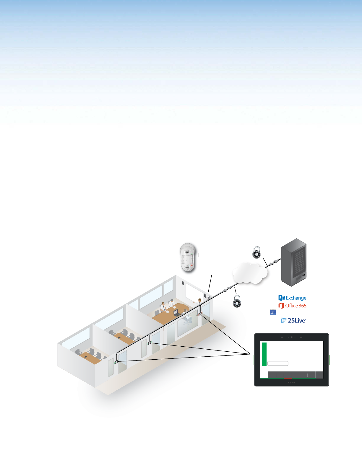
About the Room Scheduling System
Room Agent software uses Extron TouchLink Scheduling Panels and compatible
Touchlink Pro touchpanel as full-feature room booking appliances that conveniently display
meeting information and availability for rooms (see figure 1).
®
Exchange™,
Extron
https
OCS 100W
Occupancy
Sensor
TCP/IP
Network
Network Storage
https
oom
R
ce
en
fer
e
on
C
leas
n
e
ved
R
Mai
m
a
0
:0
1
eser
0
R
m-1
:3
1
0a
1
til
0:3
n
0
1
3
u
:
1
d
ten
Ex
m
p
m
1
a
1
3
:
0
0
1
3
:
4
2
1
1
0
2
,
6
2
m
r
p
e
2
b
1
m
e
t
p
0
e
3
S
:
1
1
m
a
1
1
0
3
:
0
1
om
o
R
ce
en
fer
on
le
C
n
b
Mai
Availa
e
v
er
0
3
:
es
1
R
m
p
m
1
a
1
3
:
0
0
1
3
:
4
2
1
0
2
,
6
2
m1
r
p
e
2
b
1
m
e
t
p
0
e
3
S
:
1
1
m
a
1
1
0
3
:
0
R
VC
D
V
D
C
M
O
A
D
C
P
TO
P
A
L
PC
N
O
F
F
O
E
AY
L
T
P
IS
MU
D
N
P
E
U
RE
C
S
N
E
WN
RE
O
C
D
S
oom
R
ce
en
fer
on
le
C
n
Mai
ailab
Av
e
v
0
er
3
:
1
es
R
m
p
m
1
a
1
3
0:
0
1
3
:
4
2
1
1
0
2
,
6
2
m
r
p
e
2
b
m
e
t
p
0
e
3
S
:
1
1
m1
a
1
1
0
3
:
0
R
C
V
VD
D
C
M
O
A
D
C
P
TO
P
A
L
C
P
N
O
F
F
O
E
AY
T
L
P
IS
MU
D
N
P
E
U
RE
C
S
N
E
WN
RE
O
C
D
S
1
1
Google Calendar
Main Conference Room
Available
Reserve
January 10, 10:33am
10:30
11am 12pm 1pm11:3012:30 1:30
Extron
TLS 725M
7" Wall Mount
TouchLink Scheduling
Touchpanel
Figure 1. Typical Extron Room Scheduling System Application
Room Scheduling System • Introduction 1
Page 8
Compatible panels include the following models:
• TLS 520M • TLS 1022T
• TLS 525M • TLS 1025M
• TLS 525M NC • TLS 1025M NC
• TLS 725M • TLP Pro 520M
• TLS 725M NC • TLP Pro 720M
• TLS 1022M • TLP Pro 720T
NOTES:
•
The TLS models shown above ship with the latest firmwar
system; no firmware update is required.
•
The TLP Pr
Existing panels in your system can be updated with scheduling firmware but are no
longer recommended as dedicated scheduling units.
With Room Agent, one or more panels can be connected directly to and become clients
of Microsoft Exchange, Office 365, Google Calendar, and CollegeNET 25Live. The network
traffic generated by panel and server communication is minimal.
As clients, the panels require no special programming. Users can book a room from any
device connected to the room calendar, including their mobile devices or a connected
panel.
Room Agent software, installed on a computer with network access, allows system
administrators to set up the Extron TouchLink Scheduling panels as room scheduling
appliances by filling in the required fields that correspond with areas of the user interface.
Customization options allow a variety of fields to be shown or hidden, depending on user
preference.
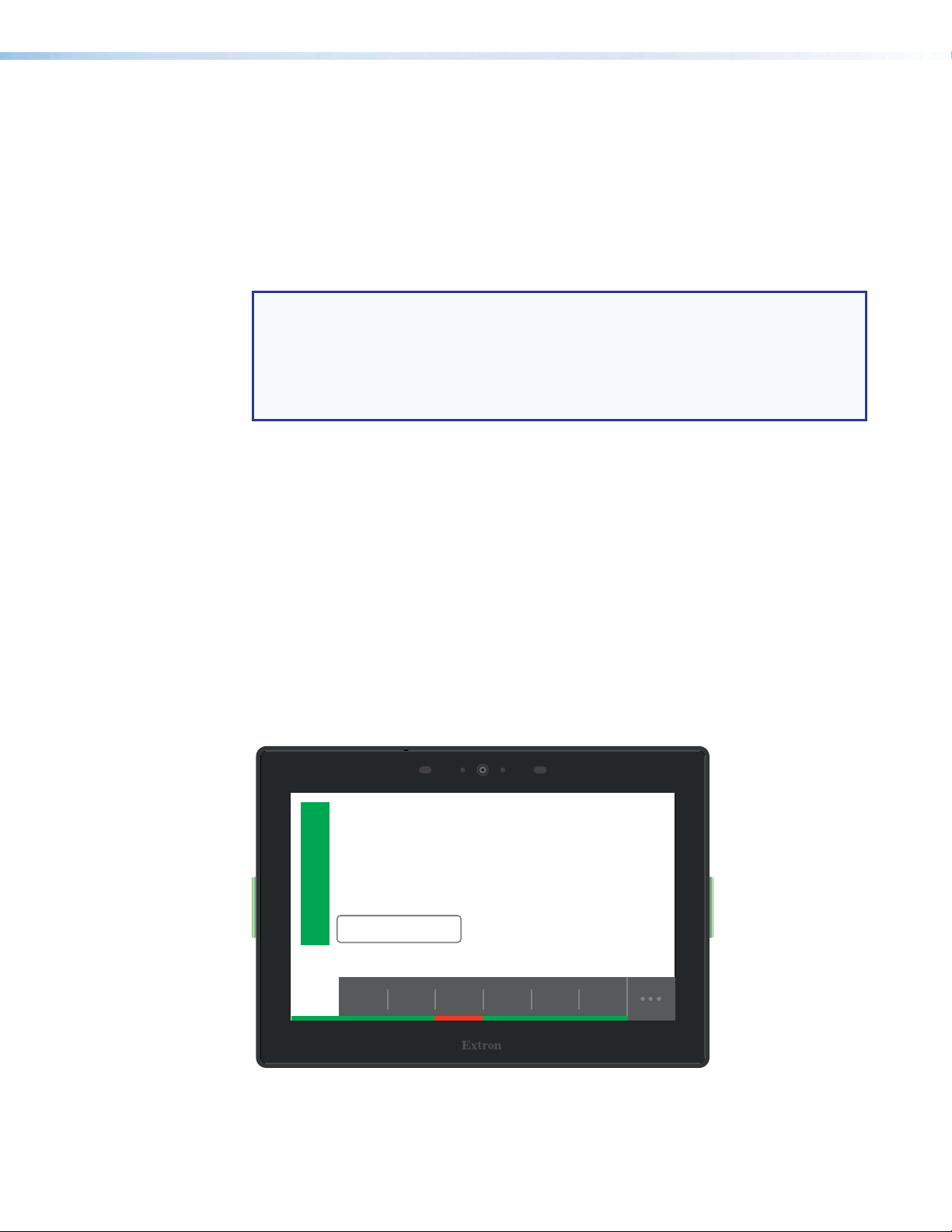
Booking a room from the panel is as easy as tapping the
intuitive interface also provides at-a-glance room availability and a timeline view of the status
of the room for half a day (see figure 2). In addition to the customizable panel interface,
bright LEDs within the bezel provide at-a-glance room availability status from down the hall.
o models shown above are included for legacy completeness only.
Reserve button on the panel. The
e for the scheduling
Main Conference Room
Available
Reserve
January 10, 10:33am
10:30
Figure 2. Typical Room Display on a TLS 725M Scheduling Panel
11am 12pm 1pm11:3012:30 1:30
Room Scheduling System • Introduction 2
Page 9

Extron TouchLink Schedulers seamlessly tie to a Microsoft Exchange server, Office 365,
Google Calendar, or CollegeNET 25Live without complicated setup or programming. Simply
connect the panel to your computer, open the free Room Agent software, and fill in the
required user interface fields. You can then make on-demand reservations from the panel,
computer, or any smartphone or tablet that connects to Microsoft Exchange, Office 365,
Google Calendar, or CollegeNET 25Live . Customization options allow fields to be shown or
hidden, depending on user preference.
System Benefits
The Room Scheduling System can be integrated into any network and requires minimal
network bandwidth for communication between each panel and the room calendar server.
Benefits of being room calendar server clients, communicating directly with the room
calendar server, include:
• Ensures the security of information — Each panel maintains a separate connection
to a dedicated resource calendar that is assigned to the room associated with the panel
through Exchange, Office 365, Google Calendar, or CollegeNET 25Live. Each resource
calendar has a unique username and password that the panel uses to connect to the
server. Administrators can manage the information of each room scheduling panel
using tools, accounts, and privileges provided by their Exchange, Office 365, Google
Calendar, or CollegeNET 25Live console.
Simplifies system management
•
management for the administrator, and does not require any middleware or additional
products to be placed on the network.
Eliminates a single point of failur
•
no middleware or intermediate server between the panels and the calendar server,
eliminating the possibility of a single point of failure.
— This direct communication simplifies user access
e — The Room Scheduling System requires
Security Overview
• All communications between the Room Agent software and the panels, and between
the panels and the calendar room server are encrypted.
• Each conference room is assigned a unique room mailbox. This mailbox is restricted so
that it cannot be used for interactive log-ons (the ability to send or receive e-mail).
• As part of the Room Agent software configuration process, the administrator enters
the authentication information for each room. These values are sent as part of the
configuration file to the panel (see Communications Settings Window on page 19).
No other user ids or passwords are used.
The softwar
•
interface it is obscured, and any sensitive information is encrypted when stored on the
administrator PC.
Administrators can choose to save the panel configurations, including the account
•
cr
edentials, on their PCs in a password-protected file.
NOTE: The protected configuration files include the authentication data for each
account. Use discretion when allowing access to these files.
• All panels are password protected. The system administrator can change the panel
password from the configuration software.
NOTE: All panels ship with the default, case-sensitive, password “extron.” Extron
strongly recommends that you change the password for each panel during the
configuration process.
e encrypts the account data. If a password is displayed on the user
Room Scheduling System • Introduction 3
Page 10

Network Traffic
The traffic generated on the network consists of requests for data and responses from the
room calendar server. Communications occur at regular intervals, such as when requesting
meetings, sending meeting invitations, or when administrators retrieve an activity file for a
room from the panel. Panel configuration, typically completed once during the initial setup
of the system, also produces traffic on the network. The panel provides options to create
an ad hoc meeting, extend a meeting, end a meeting, and confirm a meeting using the
Check-In button, provided that these options were made available to the user when the
administrator configured the panel.
Compatible Panels
The following Extron panel models are compatible with the Room Agent software:
• TLS 520M and TLP Pro 520M Panels — A 5-inch (measured diagonally),
wall-mounted panel with an 800x480 capacitive glass touchscreen.
• Dimensions — Enclosure: 5.43" W x 3.74" H x 1.64" D
(13.8 cm W x 9.5 cm H x 4.2 cm D)
Faceplate: 6.31" W x 4.61" H (16.0 cm W x 11.7 cm H)
• Mounting options —
• The panel can be mounted in a wall.
• The panel can be mounted on a non-porous surface, such as a conference
room window with the optional Extron SMB 1 Low Profile Surface Mount Box
and GMK 1 Glass Mount Kit.
• TLS 525M Scheduling Panel — A 5-inch (measured diagonally), wall-mounted panel
with an 800x480 capacitive glass touchscreen.
• Dimensions — Enclosure: 6.08" W x 4.03" H x 1.22" D
(15.4 cm W x 10.2 cm H x 3.1 cm D)
• Mounting options —
• TLS 725M Scheduling Panel — A 7-inch (measured diagonally), wall-mounted panel
• TLS 1022M Scheduling Panel — A 10.1-inch (measured diagonally), wall-mounted
• The panel can be mounted in a wall with an optional RWM 1 Recessed Wall
Mount Kit.
• The panel can be mounted on a non-porous surface, such as a conference
room window with the optional Extron SMK 1 Surface Mount Kit.
with a 1024x600 capacitive touchscreen.
• Dimensions — 7.24" W x 5.05" H x 1.20" D
18.39 cm H x 12.83 cm H x 3.05 cm D
• Mounting options — The panel can be mounted on a non-porous surface, such
as a conference room window with the optional Extron SMK 2 Low Profile Surface
Mount Kit. It can be mounted to a wall with the optional RWM 2 Recessed Wall
Mount Kit.
panel with a 1024x600 capacitive touchscreen.
• Dimensions — 7.58" H x 10.51" W x 0.80" D
(193 mm H x 267 mm W x 20 mm D)
• Mounting — The panel can be mounted in a wall.
Room Scheduling System • Introduction 4
Page 11

• TLS 1022T Scheduling Panel — A 10.1-inch (measured diagonally), wall-mounted
panel with a1024x600 capacitive touchscreen.
• Dimensions — 7.58" H x 10.51" W x 0.80" D
(193 mm H x 267 mm W x 20 mm D)
• Mounting — The panel can be mounted outside a conference room by removing
the base and using an optional Extron LPVM-1 Low Profile VESA
Mount.
• TLS 1025M Scheduling Panel — A 10.1-inch (measured diagonally) wall mounted
panel with a 1280x800 capacitive touchscreen.
• Dimensions — 6.84" H x 10.13" W x 1.26" D
(174 mm H x 257 mm W x 32 mm D)
• Mounting — The panel can be mounted on a non-porous surface, such as a
conference room window with the optional Extron SMK 3 Low
Profile Surface Mount Kit. It can be mounted to a wall with the
optional RWM 2 Recessed Wall Mount Kit.
• TLP Pro 720M Touchpanel — A 7-inch (measured diagonally), wall-mounted panel
with an 800x480 resistive glass touchscreen.
• Dimensions — 6.9" H x 8.7" W x 0.5" D
(17.5 cm H x 22.1 cm W x 1.3 cm D)
• Mounting — The panel can be mounted in a wall.
• TLP Pro 720T Touchpanel — A 7-inch (measured diagonally) panel with an 800x480
resistive glass touchscreen.
• Dimensions — 6.1" H* x 7.5" W x 7.3" D
(15.5 cm H* x 19.0 cm W x 18.6 cm D)
(*Maximum height includes the base, which is discarded for
optional rack mounting.)
• Mounting — The panel can be mounted outside a conference room by removing
All panels can receive power and communication over a single Ethernet cable. Power over
Ethernet (PoE) eliminates the need for a local power supply. PoE requires a PoE injector,
which is sold separately.
the base and using an optional Extron LPVM-1 Low Profile VESA
Mount.
Features
• Make on-demand reservations from the panel, computer, or any smartphone or tablet
that connects to Microsoft Exchange, Office 365, Google Calendar, and CollegeNET
25Live.
• Make meeting rooms available as soon as a scheduled meeting ends.
• Deploy a single panel, or multiple panels with similar settings very easily.
• Room Agent software provides easy integration with Microsoft Exchange 2007, 2010,
2013, and 2016, as well as Office 365 for convenient scheduling right from Outlook.
• No annual subscription or maintenance fees.
• Each TouchLink panel model communicates directly with Microsoft Exchange, Office
365, Google Calendar, and CollegeNET 25Live.
• All communication between the panel and Microsoft Exchange, Office 365, Google
Calendar, or CollegeNET 25Live is encrypted and secure.
Room Scheduling System • Introduction 5
Page 12

• Two bright LED indicators make it easy to see if a room is occupied or available even
from down the hall.
• Two color themes, custom loaded background images, and transparency controls
provide personalized branding options.
• Power over Ethernet - PoE allows the room scheduling panel to receive power and
communication over a single Ethernet cable, eliminating the need for a local power
supply.
• Multi-language support – Extron Room Scheduling supports
languages. See Supported Languages on page 62 for a complete list
• Check in button confirms attendance for the scheduled meeting and retains the
reserved status of the room, even if the start of the meeting is delayed.
• Optimize meeting room usage by automatically releasing an inactive room using
occupancy sensors with TLS 520M, TLS 525M, TLS 725M, TLP Pro 520M, and
TLS 1025M panels
• Customizable date and time formats with a preview showing how the user interface will
look on the panel.
• Customizable room availability hours allow you to select the start and end times for the
availability of a room.
• View details of the meetings scheduled for the day.
• Each panel now captures and retains a downloadable scheduling activity file that
provides Exchange information as well as information input directly on the panel.
• Exchange auto-discovery streamlines system setup.
• Room Agent software can handle all panel firmware updates.
a number of different
.
Room Scheduling System • Introduction 6
Page 13

Panel Overview
11
89
22222222223
44444444444
55
Room Available Display Room Unavailable Display
This section describes operating the scheduling system from the distributed scheduling
panels. Topics include:
• Overview
This section presumes that you have installed and configured the Extron Room Agent
software and the desired calendar server. See the following sections if necessary:
• Room Agent Installation and Configuration, beginning on page 11
• Microsoft Environment Setup, beginning on page 50
•
Google Calendar Envir
Overview
Once the system is installed and configured, you can use a scheduling panel (see figure 3)
to check the availability of the associated room and to reserve a room now or in the future.
The display is highly customizable with the Room Agent software (see Layout tab on page
37), so your panels may not exactly resemble the sample displays shown below.
11
1111111
onment Setup, beginning on page 57
111111111
333333333
6666666666
55
5555555
Figure 3. Typical Room Scheduling System Panel Displays
Data fields (see the next page)
1
Room available (green) flag (see the next page)
2
Room unavailable (red) flag (see the next page)
3
Timeline (see the next page)
4
Full day (
5
Reserve button (see page 9)
6
Extend button (see page 9)
7
Release button (see page 10)
8
Check in button (see page 10)
9
. . .
) button (see page 9)
77777777888888888
77
444444444
999999999
555555555
Room Scheduling System • Panel Overview 7
Page 14

Data fields (see figure 3 on the previous page) — Five fields, of various type sizes,
1
each of which can display a variety of informational messages, defined using the Room
Agent software (see Layout tab on page 37. Four fields are above and one is below the
position of the Reserve button (6, the Room Available display shown in figure 3) or
Extend button (
blank or can display any one of the following:
• The room name
• The meeting subject
• The meeting organizer (full name or first initial and last name)
• The meeting duration
• The current date, time, or both, displayed in a variety of formats (such as 12-hour or
24-hour time)
Room available (green) flag (see figure 3) — Indicates the room is free for the
2
selected block of time (see the Timeline [4]). When the room is free, the Reserve (6)
button may also be displayed (if it is programmed to appear using the Room Agent
software, see Layout tab.
Green LEDs on the panel bezels provide at-a-glance room availability status from down
the hall.
Room unavailable (red) flag (see figure 3) — Indicates the room is reserved for the
3
selected block of time (see the Timeline [4]). When the room is reserved, the Extend
(7), Release (8), and Check in (9) buttons may also be displayed (if they are
programmed to appear using the Room Agent software, see Layout tab).
Red LEDs on the panel bezels provide at-a-glance room availability status from down
the hall.
, the Room Unavailable display) on the panel. Each field can be left
7
NOTE: These indicators reflect the reservation only, not if the actual scheduled
meeting has taken place.
Timeline (see figure 3) — Indicates a 4-hour span of time, in half-hour increments,
4
starting from the current half hour. The panel displays the controls and indicators for a
selected half-hour block. Unless you have selected a different block, the current half
hour is the time block displayed. The bottom edge displays the availability of the room
for the entire 4 hours; green is free, red is reserved.
The block selected (white) is usually the current half-hour. To select a different block
of time for a proximately 5 seconds, touch the desired half-hour increment. The other
panel controls, such as Reserve (6) and Release (8), are displayed for the selected
block of time, whether the current or future half hour block.
NOTE: The timeline increments are half-hour blocks, but the display of availability
and unavailability along the bottom edge is not limited to half hours. See the brief
meeting in the 9:00 block on the Room Unavailable display in figure 3.
Room Scheduling System • Panel Overview 8
Page 15
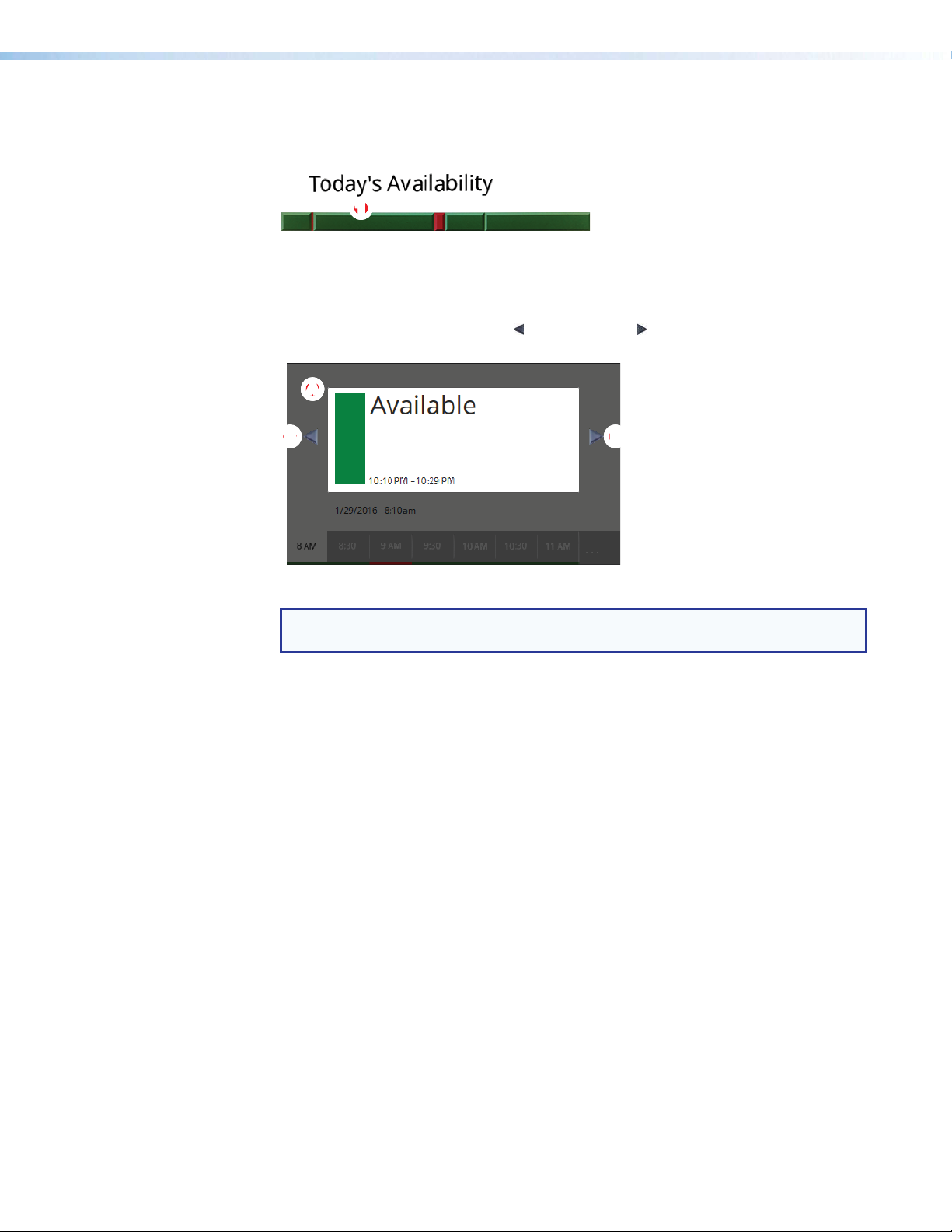
Full day (
91011121 23456789876
BBBBBBBBBBB
5
timeline of the full day availability for approximately 5 seconds (see figure 4). You can set
the starting and end time of the timeline.
. . .
) button (see figure 3 on page 7) — Touch this button to display a
1111111111
Figure 4. Today’s Availability Display
Touch on the
an inset (figure 5, A) showing just the availability of a block of time. This inset has no
controls within it, but the scroll left ( ) and scroll right ( ) buttons (B) on either side of
the inset allow you to step the time that is displayed in the inset backward and forward.
Today’s Availability timeline (figure 4,
AAAAAAAAAA
BBBBBBBBB
Figure 5. Today’s Availability Inset Display and Scroll Buttons
NOTE: If the panel has no connection with the calendar server, the Full day button
is displayed in red (
Reserve button (see figure 3) — This button appears on the room available display
6
when two conditions are met:
• The room is available in the selected 30-minute block on the timeline (see
previous page).
• The button is programmed to appear using the Room Agent software (see Layout
tab on page 37).
Touch the button to reserve the room for the selected 30-minute block. The panel
displays the red
the meeting subject field, if enabled (see Layout tab) displays the walk-up Subject
message. The default message is “adHoc,” but this can be changed.
Extend button (see figure 3) — This button appears on the room unavailable display
7
when two conditions are met:
• The room is available directly after the unavailability selected on the timeline (
The available block can be:
• The selected 30-minute block if the unavailability is less than 30 minutes.
• The 30-minute block directly after the selected block if the unavailability is in a
full 30-minute block.
• The button is programmed to appear using the Room Agent software (see Layout
tab).
Touch the button to extend the reservation until the next top or bottom of the hour (X:00
or X:30) for the selected 30-minute block.
. . .
) and the timeline that pops up displays no meaningful data.
Room unavailable flag (
) for the selected 30-minute block and
3
) to temporarily pop up
1
on the
4
4
).
Room Scheduling System • Panel Overview 9
Page 16

Release button (see figure 3 on page 7) — This button appears on the room
8
unavailable display when two conditions are met:
• The room is unavailable in the selected 30-minute block on the timeline (see
page 8).
• The button is programmed to appear using the Room Agent software (see Layout
tab on page 37).
Touch the button to release the reservation. The panel displays the green Room
available flag (
enabled (see Layout tab) displays the message Available.
Check in button (see figure 3) — This button appears on the room unavailable display
9
when two conditions are met:
• The room is unavailable in the selected 30-minute block on the timeline (
• The button is programmed to appear using the Room Agent software (see Layout
tab).
How long Check in can be displayed, before and after the scheduled start of the
meeting, can be programmed using the Room Agent software.
Touch the button to confirm that the room is taken.
If the button is not touched, and depending on the programming, the panel:
• Automatically releases the room
• Hides the Check in button
• Does nothing
) for the selected 30-minute block and the meeting subject field, if
2
4
4
).
on
Room Scheduling System • Panel Overview 10
Page 17

Room Agent Installation and Configuration
NOTES: This manual assumes that one or more panels are already installed, cabled, and
ready to serve as room booking appliances.
•
Installation
• Configuration
vailable Network Adapters
e
Installation
• Show A
•
Update Firmwar
The Room Agent software is available at no charge at www.extron.com.
Minimum System Requirements
• CPU — Intel® Core 2 Duo or equivalent processor
• Operating System — Windows® 7,Windows 8.1, or Windows 10
• Memory — 4 GB of RAM
• Hard disk space — 500 MB of available hard disk space
• Display Resolution — 1280 x 768 minimum
• Network connection — A data transfer rate of 10 Mbps. Recommended: 100 Mbps.
Micr
•
osoft .NET Framework 4.5.1
Room Scheduling System • Room Agent Installation and Configuration 11
Page 18
Install the Software
The Room Agent software, version 1.5 or newer, is available on the Extron website.
Download and install the program as follows:
NOTES:
• Steps 1 through 6 are also used to download a firmware update package.
This pr
•
browser you use, some steps or indications may be different.
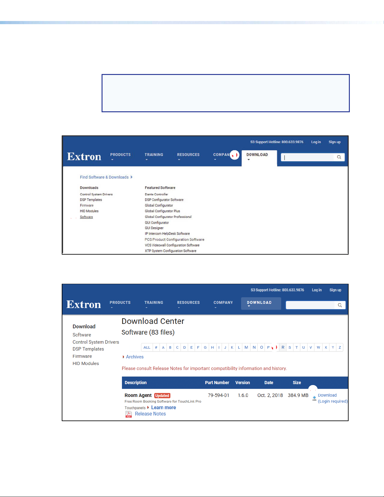
1. Visit the website www.extron.com and momentarily rest the cursor over the
Download tab (see figure 6, 1). The Find Software & Downloads links appear.
22222222
22
ocedure was written using Microsoft
1111111111
®
Internet Explorer®. Depending on the
Figure 6. Downloading a Software Package
2. Click the Software link (
). The main download page opens (see figure 7).
2
11111111
11
2222222222
Figure 7. Downloading from the Main Download Page
3. Click the R filtering letter (see figure 7,
) to jump to the nearest page of downloads.
1
Room Scheduling System • Room Agent Installation and Configuration 12
Page 19

4. Click Download for Room Agent to download (see figure 7, 2 on the previous page).
The Log in dialog box appears (see figure 8).
1111111111
33
33333333
55555555
55
44
44444444
22
22222222
Figure 8. Log in Dialog Box
5. Enter the E-Mail address and Password associated with your Extron website account
(1).
TIPS:
• Click Sign up (2) to obtain website credentials.
• Click Keep me logged in (
• Enter your registered email address and click Retrieve Password (
have forgetten your credentials.
Click Log in to copy the software to the computer (5).
6.
7.
If your br
similar confirmation (see figure 9, 1).
owser asks you to confirm that you want to continue, click
) to eliminate steps 5 and 6 in future downloads.
3
) if you
4
Run or make a
1111111111
Figure 9. Download Warning and Confirmation
NOTE: Figure 9 may appear different or may not appear at all, depending on your
Web browser choice and its security settings.
Room Scheduling System • Room Agent Installation and Configuration 13
Page 20

8. Follow the on-screen instructions. By default, the installation creates the following folder
and group folder. It places the entries shown below into correct group folders and on
the PC desktop:
• Folder — C:\Program Files\Extron\Extron Room Agent
NOTE: C:\Program Files(x86)\... for 64-bit Windows OS.
Configuration
•
oup folder —
Gr
•
Room Agent Help
• Room Agent Quick Help
• Room Agent
• Uninstall Room Agent
Before you start the Room Agent software:
1. Ensure all the panels have been mounted and are connected to the network.
2. Ensure you know whether Microsoft Exchange, Office 365, Google Calendar, or
CollegeNET 25Live is to be the calendar server and the network location of the server.
3. Ensure that you know the IP addresses of all the panels in the system (especially those
that are not on the same subnet as the control PC).
4. Ensure that you know the passwords for all the panels. By default, the password is
"extron". If the passwords have not already been changed, you should do so during
configuration.
Extron Electronics\Extron Room Agent
Room Scheduling System • Room Agent Installation and Configuration 14
Page 21

Start the Program
NOTE: Also, see System Communications Overview on page 61.
Start the Extron Room Agent software by double-clicking the desktop icon or as follows:
Click
1.
Room Agent.
The Room Agent software opens in the Panel Management view (the Panel
Management tab selected) (see figure 10).
1111111111
Start > All Programs > Extron Electronics > Extron Room Agent > Extron
22
22222222
Figure 10. Room Agent Startup — Panel Management View
Room Scheduling System • Room Agent Installation and Configuration 15
Page 22

Automatically Discover Panels
11111111111111
Automatically discover panels that are on the same subnet as the computer running the
Room Agent software as follows:
NOTE: Any panels not on the same subnet as the computer running Room Agent must
be added using the Manually Add Panels pane (see “Manually Add Panels”).
1. If Panel Management view is not currently displayed, click the Panel Management tab.
2. Click the Discover button above the Auto Discovered Panels pane (see figure 10,
on the previous page).
1
The Discover button becomes the Stop Discovery button. Panels that are located
on the same subnet are automatically discovered and displayed (see figure 11).
Figure 11. Auto Discovered Panels Pane
NOTES:
• TLS scheduling panels ship with scheduling firmware installed. All except the
TLS 525M, TLS 725M, or TLS 1025M require firmware version 2.01.0010-b001
or higher to connect to them. TLS 525M, TLS 725M, or TLS 1025M requires
version 1.00.0004-b001.
•
TLP Pr
requires that scheduling panels run different, scheduling, firmware, version
2.01.0010-b001 or higher to connect to them.
For either family of
•
connect to this device, click OK in the message dialog box, STOP HERE
and update the panel firmware (see Update Firmware on page 46, beginning
at step 5).
o touchpanels ship with control firmware installed. Room Agent
panel models, if you receive the message
Cannot
3. When all of the panels are displayed, click the
search (see figure 11, 1).
Manually Add Panels
Manually add panels that are on a different subnet than the computer running the Room
Agent software as follows:
1. If Panel Management view is not currently displayed, click the Panel Management tab.
2. Click the Add New button above the Manually Added Panels pane (see figure 10, 2).
The Add New Panel dialog box opens (see figure 12).
1111111111
Figure 12. Add New Panel Dialog Box
Stop Discovery button to end the
22
22222222
33333333
33
Room Scheduling System • Room Agent Installation and Configuration 16
Page 23

3. Enter the IP address of the desired panel in the IP Address/Hostname: field
(see figure 12, 1 on the previous page).
4. If the panel is password protected, enter the password in the Password: field
(2).
NOTE: All panels ship with the default, case-sensitive, password “extron”.
5. Click the Add button (
adds it to the Manually Added Panels pane (see figure 13).
NOTES:
TLS scheduling panels
•
TLS 525M, TLS 725M, or TLS 1025M require firmware version 2.01.0010-b001
or higher to connect to them. TLS 525M, TLS 725M, or TLS 1025M requires
version 1.00.0004-b001.
TLP Pr
•
requires that scheduling panels run different, scheduling, firmware, version
2.01.0010-b001 or higher to connect to them.
For either family of
•
connect to this device, click OK in the message dialog box, STOP HERE
and update the panel firmware (see Update Firmware on page 46, beginning
at step 5).
o touchpanels ship with control firmware installed. Room Agent
). Room Agent searches for the requested panel and, if found,
3
ship with scheduling firmware installed. All except the
panel models, if you receive the message
Cannot
Figure 13. Panel Management View with Panels Assigned
Room Scheduling System • Room Agent Installation and Configuration 17
Page 24

Panel Management Tab
Connect to the panel
Each panel requires setup as follows:
1. Click the Setup button for the panel to be set up.
NOTE: The button deletes a panel from the list.
The Panel Connection dialog box opens (see figure 14).
1111111111
Figure 14. Panel Connection Dialog Box
22222222
22
2. If applicable, enter a password in
NOTE: All panels ship with the default, case-sensitive, password “extron”.
3. Click the
The Room Agent connects to and synchronizes with the panel. Once synced, Room
Agent displays the Device Management window with either the Communication
Settings tab (see figure 15 on the next page) or General Settings tab (see
figure 16 on page 20) selected.
Connect button (
Password block (see figure 14,
).
2
1
).
Room Scheduling System • Room Agent Installation and Configuration 18
Page 25

Communication Settings window
The Communication Settings tab on the Device Management window (see figure 15)
provides a set of tools for managing the following internet settings of the connected panel:
¤¤
¤¤¤¤¤¤¤¤
11
11111111
22222222
22
33333333
33
44444444
44
55555555
55
66
66666666
77
77777777
Figure 15. Device Management Window, Communications Settings
MAC Address (displayed only)
1
IP Address
2
Subnet Mask
3
Hostname
4
When the DHCP checkbox (see figure 15, 7) is selected, only the Hostname can be edited.
All other settings (other than DHCP itself) are displayed only and unavailable for editing. To
edit all settings (other than the MAC address), DHCP must be deselected (unchecked).
8888888888
99999999
99
¢¢
¢¢¢¢¢¢¢¢
££££££££
££
Default Gateway
5
DNS (Domain Name System) server
6
DHCP (Dynamic Host Configuration Protocol)
7
NOTE: If you configure the panels with a static IP address and you use a host name for
the exchange server, ensure that you provide the DNS server address.
The Communication Settings tab also allows users to change the password of the panel.
NOTE: All panels ship with the default, case-sensitive, password “extron”. Extron
recommends that you change the password.
Change the password as follows:
1. Click (select) the Change Touch Panel Password checkbox (8).
2. Enter the new password in the Password (9) and Confirm Password (¢) fields.
Once you have made all desired changes available from the Communication Settings
tab, click either the OK button (
General Settings tab (¤, then general settings are displayed, see figure 16 on the
next page).
Room Scheduling System • Room Agent Installation and Configuration 19
, the Device Management window closes) or the
£
Page 26

General Settings window
The General Settings tab on the Device Management window (see figure 16) provides a
set of tools for managing display, time, and audio settings of the connected panel.
88
88888888
77777777
77
6666666666
11111111
11
22
22222222
33
33333333
44444444
44
55555555
55
Figure 16. Device Management Window, General Settings
Display Brightness — Set the panel illumination brightness, from 0 to 100 (percent)
1
using this fader control.
Display Sleep Mode — Toggle Sleep mode On and Off by selecting the appropriate
2
radio button. If Sleep mode is On, use the Minutes field to specify between 1 and 99
minutes.
Timezone — Use the drop-down list to select the appropriate time zone.
3
Synchronize Clock with — Toggle the clock synchronization source between the
4
Calendar server and NTP (Network Time Protocol — a networking protocol for clock
synchronization between computer systems) by selecting the appropriate radio button.
NOTE: If you select NTP, specify the path to the NTP server in the Server path:
field (5).
Server path: (available only if NTP is selected in 4) — Specify a path for the NTP
5
server.
Audio Volume — Set the panel audio volume, from 0 to 100 (percent) using this fader
6
control.
Once you have made all desired changes available from the General Settings tab, click
either the OK button (7, the Device Management window closes) or the Communication
Settings tab (8, then communication settings are displayed, see figure 15 on the
previous page).
Room Scheduling System • Room Agent Installation and Configuration 20
Page 27

11111111111111
Panel Configuration Tab
The Panel Configuration window (see figure 17) provides a set of tools for selecting
among the supported calendar servers and managing the settings of the selected server.
NOTE: Until you designate the calendar server for your system, only the Select a
Calendar Type drop-down list (
) is available for selection.
1
2222
2222222222
Figure 17. Panel Configuration Window, Initial View
Click the
shown in figure 17. The appearance and available selections of the Panel Configuration
tab vary depending on the selection:
The function of the
Type selections. See Common Panel Configuration tab functions on page 35. For all
other functions on these windows:
• If you selected Microsoft® Exchange™, see Exchange configuration on the next
• If you selected Microsoft® Office 365™, see Office 365 configuration on page 28.
• If you selected Google Calendar™, see Google Calendar configuration on page 29.
• If you selected CollegeNET 25Live, see CollegeNET 25Live configuration on
Select a Calendar Type drop-down list (
Configuration and Activity buttons (
page.
page 33.
) and select among the choices
1
) is common to all Calendar
2
Room Scheduling System • Room Agent Installation and Configuration 21
Page 28
Exchange configuration
2222222222111111111133333333334444444444
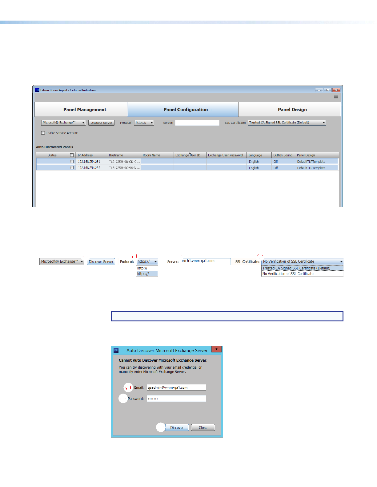
When you select Microsoft® Exchange™ (see figure 17, 1 on the previous page), the
Panel Configuration window displays the settings necessary to connect to the panels
and configure them for Microsoft Exchange (you may also commonly hear this referred to as
“Exchange On Premises” or “on Prem”) (see figure 18).
Figure 18. Panel Configuration Window, Exchange View
Connect to the server
Connect to the Microsoft Exchange server as follows (see figure 19):
Figure 19. Establishing a Connection the Microsoft Exchange Server
1. If necessary, click the Protocol drop-down list and select between https:// and
http:// (see figure 19,
NOTE: https:// is the correct selection for virtually all applications.
2.
Click the Discover Server button (2). The Auto Discover Microsoft Exchange
Server dialog box opens (see figure 20).
1111111111
22222222
22
1
).
33333333
33
Figure 20. Auto Discover Dialog Box
Room Scheduling System • Room Agent Installation and Configuration 22
Page 29

3. Enter your Email credentials (see figure 20, 1 on the previous page) and the
Password (
4. Click the Discover button (figure 20, 3). Room Agent finds the calendar server
and fills in the Server field (see figure 19, 3 on the previous page). Room Agent is
connected to the server.
5. If necessary, change the SSL Certificate drop-down list
• Trusted CA Signed SSL Certificate — Directs Room Agent to validate that
certificates are signed by one or more trusted Certificate Authorities. This is the
correct selection for most applications.
• No Verification of SSL Certificate — Bypasses the validation. Use this
selection if the connecting Exchange server is using self-signed SSL certificates.
NOTE: Consult the Exchange administrator for the connecting server if you are
unsure about which is the correct selection.
2
).
selection
(figure 19, 4):
Configure panels
Configure the panels for Exchange as follows (see figure 21):
1111
1111111111
3333333333
3333 44444444444444 55555555555555 66666666666666 77777777777777 88888888888888
22222222222222
Figure 21. Panel Configuration
NOTE: The Enable Service Account checkbox (see figure 21, 1) allows one or more
service accounts to be used to configure the panels. See Use service accounts
beginning on the next page to configure and use service accounts.
Select (check) one or mor
1.
2. For the direct entry settings, Room Name (3), Exchange User ID
(Exchange credentials, 4), and Exchange User Password (5):
NOTES:
• If service accounts are enabled, the Exchange User ID and Exchange User
Password columns are titled Service Account and Room Resource Account
(see figure 22 on the next page).
• The Exchange User ID requires the User Principal Name (UPN, the name of a
Windows network user in an e-mail address format) for the room resource user
ID. The UPN must have an SMTP e-mail address assigned to it.
Status checkboxes (
e
2
).
a. Click in the desired field.
b. Type the desired value.
c. Type the keyboard <Tab> key to exit the field.
Room Scheduling System • Room Agent Installation and Configuration 23
Page 30

3.
11111111111111 22222222222222
3333333333
3333 44444444444444
For the drop-down lists, Language (see
Sound (
NOTES:
a.
b.
c.
), and Panel Design (8):
7
•
The Language menu includes a number of different languages. See Supported
Languages on page 62 for a complete list.
•
The Button Sound menu consists of On and Off.
•
The Panel Design menu includes the DefaultTLPTemplate, which is the
default that is installed as part of the Room Agent software, as well as any
templates that you have created and saved (see Templates pane on page 44).
Click in the desired field.
Click the drop-down list button ( ).
Click the desired setting.
figure 21
, 6 on the previous page), Button
Use service accounts
The Room Agent software can use the service account functions of the Exchange and
Office 365 "impersonation" feature as a single point to manage the configuration of multiple
panels. One example of this application is a facility where passwords are changed every few
months; rather than change the password on multiple panels, an administrator can change
the password of one service account tied to multiple panels.
Enable and add service accounts —
1.
If necessary, access the Exchange server Active Directory Users and Computers
window or the Office 365 Admin center page and create one or more service accounts
with valid e-mail addresses.
NOTE: The service account requires the UPN, the name of a Windows network
user in an e-mail address format. The UPN must have an SMTP e-mail address
assigned to it.
2.
On the Room Agent software Panel Configuration page, select the Enable Service
Account checkbox (see figure 22,
(
). The Exchange User ID and Exchange User Password columns become Service
2
Account (
Figure 22.
NOTE: Figure 22 shows Microsoft® Exchange™ selected. With the exception
of the selection, the appearance is identical when
selected.
) and Room Resource Account (4).
3
Enable Service Accounts
). The Service Account Manager button appears
1
Microsoft
®
Office 365™ is
Room Scheduling System • Room Agent Installation and Configuration 24
Page 31

3.
2222222222
33
33333333
44
44444444
Click the Service Account Manager button (see
The
Service Account Manager
tab selected (see figure 23, 1).
dialog box opens with the Assign Service Account
1111111111
66
66666666
55
55555555
figure 22
, 2 on the previous page).
Figure 23. Add Service Accounts
4. Enter a valid Service Account Email address (
5. Enter the Service Account Password (3).
2
).
TIP: The Service Account Password field is normally masked (•••). Select the
Show Password checkbox (
6. Click Add (5). The Add Service Account area displays the message Service
Account has been added and is ready to be assigned to panels. The account is
added to the Service Account drop-down list (6).
7. Repeat steps 4 through 6 for each service account.
) to see the password characters as you type.
4
Room Scheduling System • Room Agent Installation and Configuration 25
Page 32

Assign service accounts —
Service Accounts
Not Enabled
Service Accounts
Enabled
1. If necessary, click the Assign Service Account tab (see figure 24, 1).
1111111111
44444444
44
33
33333333
22
22222222
55555555
55
66666666
66
77
77777777
Figure 24. Assign Service Accounts
2. Select (check) one or more panel IP Address checkboxes (
TIP: Select either the Auto Discovered Panels or Manually Entered Panels
3. Select the desired service account among the entries in the Service Account
4. Click Assign (5). The selected Service Account is assigned to the designated panels
5.
6.
checkbox (3) to select all panels in that pane.
drop-down list (4).
(6).
Repeat steps 2 thr
Click Close (7). The Service Account Manager dialog box closes and the Room
Agent software returns to the Panel Configuration Window displayed. For the panels
with service accounts that are enabled, the normal Exchange User ID and Exchange
User Password columns are titled Service Account and Room Resource Account
(see figure 25).
ough 4 to assign other service accounts to other panels.
2
).
1111111111
Figure 25. Display With Service Accounts Enabled and Not Enabled
7. For each panel, enter the e-mail address used as the fully qualified room resource in the
Room Resource Account column (see figure 25,
Room Scheduling System • Room Agent Installation and Configuration 26
1
).
Page 33

Edit a service account password —
1. If necessary, open the Service Account Manager dialog box (see Enable and add
service accounts, steps 2 and 3, beginning on page 24).
2. Click the Edit Service Account tab (see figure 26, 1).
11111111
11
2222222222333333333366666666665555555555
44
44444444
Figure 26. Edit Passwords
3. Double-click in the Password field for the service account to be edited (
4. Highlight the password and type a new value (3).
5. Type the keyboard <Enter> key.
TIPS:
• The Password field is normally masked (•••). Delete the existing password to
activate the Show feature to see the password characters
as you type.
• Click Show to toggle between Show and Hide.
• After you type <Enter>, the Password field is again masked.
6. Click Close (4).
Delete a service account password —
1. If necessary, open the Service Account Manager dialog box (see Enable and add
service accounts, steps 2 and 3, beginning on page 24).
2. Click the Edit Service Account tab (see figure 26, 1).
3. Double-click in the Password field for the service account to be deleted (
4. Select (click) a service account (5).
5. Click Delete ( ) button (6).
6. Click Close (4).
2
2
).
).
Room Scheduling System • Room Agent Installation and Configuration 27
Page 34

1111
1111111111
22222222222222
Office 365 configuration
When you select Microsoft® Office 365™ (see figure 17, 1 on page 21), the Panel
Configuration window displays the settings necessary to configure the panels for
Microsoft Office 365 (see figure 27).
3333333333
3333 44444444444444 55555555555555 66666666666666 77777777777777 88888888888888
Figure 27. Panel Configuration Window, Office 365 View
NOTE: The Enable Service Account checkbox (see figure 27, 1) allows one or more
service accounts to be used to configure the panels. See Use service accounts
beginning on page 24 to configure and use service accounts.
Connect to the server
Connection to the panels is made automatically, through the Office 365 server.
Configure panels
Configure the panels for Office 365 as follows:
1. Select (check) one or more Status checkboxes (see figure 27, 2).
2. For the direct entry settings, Room Name (3), Exchange User ID (Exchange credentials,
), and Exchange User Password (5):
4
NOTES:
• If service accounts are enabled, the Exchange User ID and Exchange User
Password columns are titled Service Account and Room Resource Account.
• The Exchange User ID requires the User Principal Name (UPN, the name of a
Windows network user in an e-mail address format) for the room resource user
ID. The UPN must have an SMTP e-mail address assigned to it.
a. Click in the desired field.
b. Type the desired value.
c. Type the keyboard <Tab> key to exit the field.
Room Scheduling System • Room Agent Installation and Configuration 28
Page 35

3. For the drop-down lists, Language (see figure 27, 6 on the previous page), Button
Sound (
NOTES:
a. Click in the desired field.
b. Click the drop-down list button ( ).
c. Click the desired setting.
), and Panel Design (8):
7
•
The Language menu includes a number of different languages. See Supported
Languages on page 62 for a complete list.
The Button Sound menu consists of On and Off.
•
•
The Panel Design menu includes the DefaultTLPTemplate, which is the
default that is installed as part of the Room Agent installation, as well as any
templates that you have created and saved (see Templates pane on page 44).
Google Calendar configuration
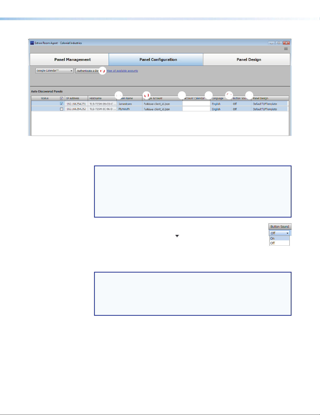
When you select Google Calendar™ (see figure 17, 1 on page 21), the Panel
Configuration window displays the settings necessary to configure the panels for Google
Calendar (see figure 28). If you select Google Calendar, you can have multiple devices using
the same calendar or multiple calendars.
22222222222222
1111111111
1111
Figure 28. Panel Configuration Window, Google Calendar View
Configure panels
NOTE: You must have downloaded a JSON file to configure panels for Google
Calendar (see Download the JSON File on page 57.
Configure the panels for Google Calendar as follows:
1. Select (check) one or more Status checkboxes (see figure 28, 1).
2. Click Authenticate a Device (2) to connect to the calendar that will be associated
with that panel. The Authenticate a Device to Google dialog box opens (see
figure 29 on the next page).
Room Scheduling System • Room Agent Installation and Configuration 29
Page 36

21
22
2222222
33
33333333
111111111
4444444444
Figure 29. Authenticate a Device to Google Dialog Box
Click Browse (1). The Open dialog box opens (see figure 30).
3.
1111111111
Figure 30. Open Dialog Box
4.
Navigate to the folder wher
5. Click Open (2). The Authenticate a Device to Google dialog box returns to the top
with the JSON file entered in the Import Credential JSON File field (see figure 29,
).
2
6. Enter a value in the Google Account field (3).
NOTE: You can enter anything for the Google Account, such as an e-mail address
or a meaningful name. The software uses this value as an identifier to keep track of
Google accounts.
7. Click Next (4). The Authenticate a Device to Google dialog box closes.
22222222
22
e you saved the JSON file. Select the file (
1
).
Room Scheduling System • Room Agent Installation and Configuration 30
Page 37

The Room Agent software retrieves a user code and prompts you to enter the code on
a Google Web page (see figure 31).
22222222
22
1111111111
33
33333333
Figure 31. User Code Dialog Box
NOTE: The Check Authorization Status button (3) is not available for selection
until after you have authenticated the device in step 9.
Click on the link (1). Room Agent opens a separate browser to the Google Device
8.
page.
9. Follow the steps on the Google Device page to authenticate the device. When the
Google Device page prompts for it, enter the User Code provided (2).
NOTE: The Product Name that you enter during Google calendar environment setup
(see step 12 on page 59) is the name that appears on the Google Device page.
When you are finished, the Check Authorization Status button in the Room Agent
User Code dialog box is enabled (
10. Click Check Authorization Status (3).
The Room Agent software checks the authorization status. Assuming no errors, it
reports Complete! (see figure 32).
3
).
1111111111
Figure 32. Completion Dialog Box
11. Click Done.
The Room Agent software appends the name of the Import Credential JSON File,
entered in step 5, to the end of the Google Account, entered in step 6, and displays
the new value in the Google Account field of the Panel Configuration window (see
figure 33, 1, on the next page).
The Panel Configuration Window displays other fields appropriate for Google
Calendar configuration.
12. For the direct entry Room Name (2) setting:
a. Click in the field.
b. Type the desired value.
c. Type the keyboard <Tab> key to exit the field.
Room Scheduling System • Room Agent Installation and Configuration 31
Page 38
77
77777777
222222222211111111116666666666
Figure 33. Panel Configuration Window, Google Calendar View, Continuation
13. For the drop-down lists in figure 33, Language (
Design (
NOTES:
• The Language menu includes a number of different languages. See Supported
•
• The Panel Design menu includes the DefaultTLPTemplate, which is the
a. Click in the desired field.
b. Click the drop-down list button ( ).
c. Click the desired setting.
14. Observe the Account Calendar field (6). The field shows the individual calendar from
the Google account. For GSuite Resource calendars, this should be the Resource
Name. If this field is left empty, Room Agent defaults to the calendar owner address.
):
5
Languages on page 62 for a complete list.
The Button Sound menu consists of On and Off.
default that is installed as part of the Room Agent installation, as well as any
templates that you have created and saved (see Templates pane on page 44).
3333333344444444445555555555
33
), Button Sound (4), and Panel
3
NOTES:
•
The Google Administrator typically assigns each r
access to all users that are allowed to book the rooms.
•
For GSuite User Accounts, the "Meeting Organizer" name corr
Google+ profile name. If the Google+ profile has not been set up, only the
organizer e-mail is displayed.
Room Scheduling System • Room Agent Installation and Configuration 32
oom a calendar and opens
esponds to the
Page 39

You can also click View all available accounts (7) to show the status of all of the
17
Google accounts that provide calendars (see figure 34).
666666665555555555
22222222
22
33
33333333
44444444
44
66
111111111
Figure 34. View All Accounts Dialog Box
NOTE: The Google Account field is the value entered in step 6 on page 30.
Click Check Authorization to poll the authorization status for all Google accounts (see
figure 35, 1). The possible authorization status are:
• pending (2)— The Google authorization for this account has been started but not yet
approved.
• authorized (3)— This account is authorized for Google Calendar.
NOTE: Before you start the authorization process, the indicated status is -(4).
Click Reconnect (5) to retrieve the user code and verification. This is similar to the device
authentication procedure, step 7 through step 10, beginning on page 30.
Click (6) to delete a selected account. Save (7) becomes available when an account is
deleted, click it to save the list of Google accounts.
CollegeNET 25Live configuration
When you select CollegeNET 25Live (see figure 17, 1 on page 21), the Panel
Configuration window displays the settings necessary to configure the panels for 25Live
(see figure 35).
777777777
11111111111111
3333333333
3333 44444444444444 66666666666666 5555555555555555555555555555 88888888888888 99999999999999 ¢¢¢¢¢¢¢¢¢¢¢¢¢¢
2222222222
2222
Figure 35. Panel Configuration Window, CollegeNET 25Live View
Room Scheduling System • Room Agent Installation and Configuration 33
Page 40

Connect to the server
Connect to the server by entering your 25Live server name in the Server field (see
figure 35, 1 on the previous page).
NOTE: This value is the full URL of the address you use to log in to your regular
CollegeNET 25Live account and has the format:
https://25live.collegenet.com/<college-name>.
Configure panels
Configure the panels for 25Live as follows:
1. Select (check) one or more Status checkboxes (see figure 35, 2).
2. For the direct entry settings, Room Name (3), User ID (4), User Password (5),
Space Name, (
NOTES:
The User ID and User Password entries must be for a user account that has
•
access to the desired space.
• The Room Name is what is displayed on the front panel. The Space Name is a
specific space that has been set up on the 25Live server in advance of Room
Agent setup. They may or may not match.
• Enter the Space Name exactly as it appears on the 25Live server.
• Enter an Event Type to be used for ad hoc events from the server.
• Event Types are created in the 25Live server. Certain Event Types in
•
• Ad hoc is a suggested default Event Type, but you can create your own on
), and Event Type (7):
6
25Live can have requirements, such as catering or facilities, that are not
applicable to ad hoc events. The requirements for these events are not
recognized by Room Agent.
An Event Type that properly coordinates with Room Agent, cannot have
any requirements beyond the Space Name and an organizer.
the 25Live server.
a. Click in the desired field.
b. Type the desired value.
c. Type the keyboard <
3. For the drop-down lists, Language (see figure 35, 8 on the previous page), Button
Sound (
NOTES:
a. Click in the desired field.
b. Click the drop-down list button ( ).
c. Click the desired setting.
), and Panel Design (¢):
9
• The Language menu includes a number of different languages. See Supported
Languages on page 62 for a complete list.
• The Button Sound menu consists of On and Off.
• The Panel Design menu includes the DefaultTLPTemplate, which is the
default that is installed as part of the Room Agent installation, as well as any
templates that you have created and saved (see Templates pane on page 44).
Room Scheduling System • Room Agent Installation and Configuration 34
Tab> key to exit the field.
Page 41

Common Panel Configuration tab functions
Send and retrieve the configuration
The send and receive configuration functions push and pull configurable settings between
the Room Agent software and one or more panels.
Send or receive one or more configurations as follows:
1. Select (check) one or more Status checkboxes.
2. Click the Send Configuration button to send the Room Agent
settings to the panels and implement them in the panels.
— or —
Click the Retrieve Configuration button to fetch configurable
settings from one or more panels and embed them in the Room
Agent settings and fields.
TIP: Or, easily retrieve the configuration for a
single panel by right-clicking the panel in the
Status column and then clicking the
pop-up Retrieve Configuration button.
The Room Agent software reports that the Status is in progress ( ) and then reports
either Config Sent. or Config Retrieved.
Retrieve and clear the activity file
Each panel maintains an activity file, a log of scheduling information; such as the meeting
subject, meeting organizer, booking date, meeting date and starting time, and duration;
among other data for the assigned room. The activity file can be retrieved and written to the
PC running the Room Agent software as an Microsoft Excel spreadsheet or cleared (erased)
from the panel. You can use data analytics tools to transform this activity data to create
usage reports.
NOTE: The panel has 4 Mb of activity file memory. The number of entries varies
depending on the size of each entry, but may number in the hundreds. When the
memory becomes full, the newest entries overwrite the oldest. There is no notification
when the memory becomes full.
Retrieve or clear one or more activity files as follows:
1. Select (check) one or more Status checkboxes.
2. Click the Retrieve Activity File button to fetch the schedule
log and from one or more panels and save it in a spreadsheet. The
Room Agent software opens the Panel Activity File dialog box (see figure 36).
Proceed to step 4.
— or —
Click the Clear Activity File button to erase the schedule log
from one or more panels.
For the clear operation, the Room Agent software reports that the Status is in
progress ( ) and then reports Cleared. and All panel activity logs have been
cleared successfuly.
3. Click OK to exit the clear operation.
Room Scheduling System • Room Agent Installation and Configuration 35
Page 42

4. Enter a name for the retrieved activity file (see figure 36, 1).
2222222222
1111111111
Figure 36. Panel Activity File
22222222
22
5. Click
Save (
progress ( ) and then reports Activity retrieved. and All activities have been
retrieved successfully.
). The Room Agent software saves the file. It reports that the Status is in
2
Retrieve a template
Templates allow you to create a number of customized panel appearances. Templates
are selectable using the Panel Design menu in the Panel Configuration window (see
figure 21, 7 on page 22 for an example). Templates can be created using a variety of tools
in the Panel Design window (see Panel Configuration Tab on page 21) and saved in the
template pane (see Templates pane on page 44).
You can retrieve the template assigned to a panel, for example to use as a starting point for
designing a new panel layout, as follows:
1. Right-click the panel in the Status column
see 1, at right).
2. Click the pop-up Retrieve Template for
Design button (
). The Retrieve Template dialog box opens (see figure 37).
2
1111111111
(see
1111111111
Figure 37. Retrieve Template Dialog Box
3. Click
Retrieve (see figure 37,
Retrieving Template ... activity indicator while it loads the template
and then automatically jumps to the Panel Design window (see Panel
Configuration Tab on page 21).
Room Scheduling System • Room Agent Installation and Configuration 36
). Room Agent software displays the
1
Page 43

33333333333333
Panel Design Tab
The Panel Design window (see figure 38) provides tools for customizing the appearance
and function of the connected panels. The window consists of the design pane (1, see
"Design pane"), the preview pane (2, see Preview pane on page 44), and the Templates
pane (3, see Templates pane on page 44).
NOTE: The preview pane contains hardcoded, sample, entries. The layout and
appearance of this pane change to reflect changes in the design pane, but, other than
the date and time, the contents, such as “Main Conference Room”, do not change.
1111111111
1111 22222222222222
Figure 38. Panel Design Window, Layout Tab Selected
Design pane
Layout tab
If necessary, click the Layout tab (see figure 39, 1 on the next page) to make changes to
the following:
• The arrangement of the fields on the display
• Whether or not you can locally (on the panel):
• Reserve the room
• Release the room
• Extend the meeting time
Room Scheduling System • Room Agent Installation and Configuration 37
Page 44

1111
1111111111
2222222222
2222
2222
2222222222
2222
2222222222
2222222222
2222
3333333333
3333
2222222222
2222
ÕÕÕÕ
ÕÕÕÕÕÕÕÕÕÕ
ÝÝÝÝ
ÝÝÝÝÝÝÝÝÝÝ
ÜÜÜÜ
ÜÜÜÜÜÜÜÜÜÜ
44444444444444 55555555555555
êêêê
êêêêêêêêêê
ëëëë
ëëëëëëëëëë
Figure 39. Panel Design Pane, Layout Tab
Data field drop-down lists — These five menus are positioned within the pane to
2
correspond to data positions on the panels and in the preview pane (see figure 38, 2
on the previous page). All menus contain the same options (see figure 39, Õ). Select
among the options to choose the data displayed in the corresponding position. Watch
the preview pane to see how your selections affect the appearance of a panel. Selecting
Blank causes no data in the associated position.
NOTE: Organization is available for selection only when you have selected
CollegeNET 25Live on the Panel Management page (see figure 17,
page 21). Organization causes the panel to display the organization associated
with the booked meeting, such as Arts & Art History in the preview pane.
Reserve: drop-down list — Use this drop-down list to select
3
whether the Reserve button appears on the panel and how it
functions. The Reserve button allows user to book the room
locally, on the panel itself. Anytime allows you to reserve any
half-hour segment displayed on the panel.
Subject field (see figure 39) — This field shows the meeting subject displayed on
Ü
the panel when a room is reserved from the panel. “adHoc” is the default subject.
Change the meeting subject as follows:
1
on
Room Scheduling System • Room Agent Installation and Configuration 38
Page 45
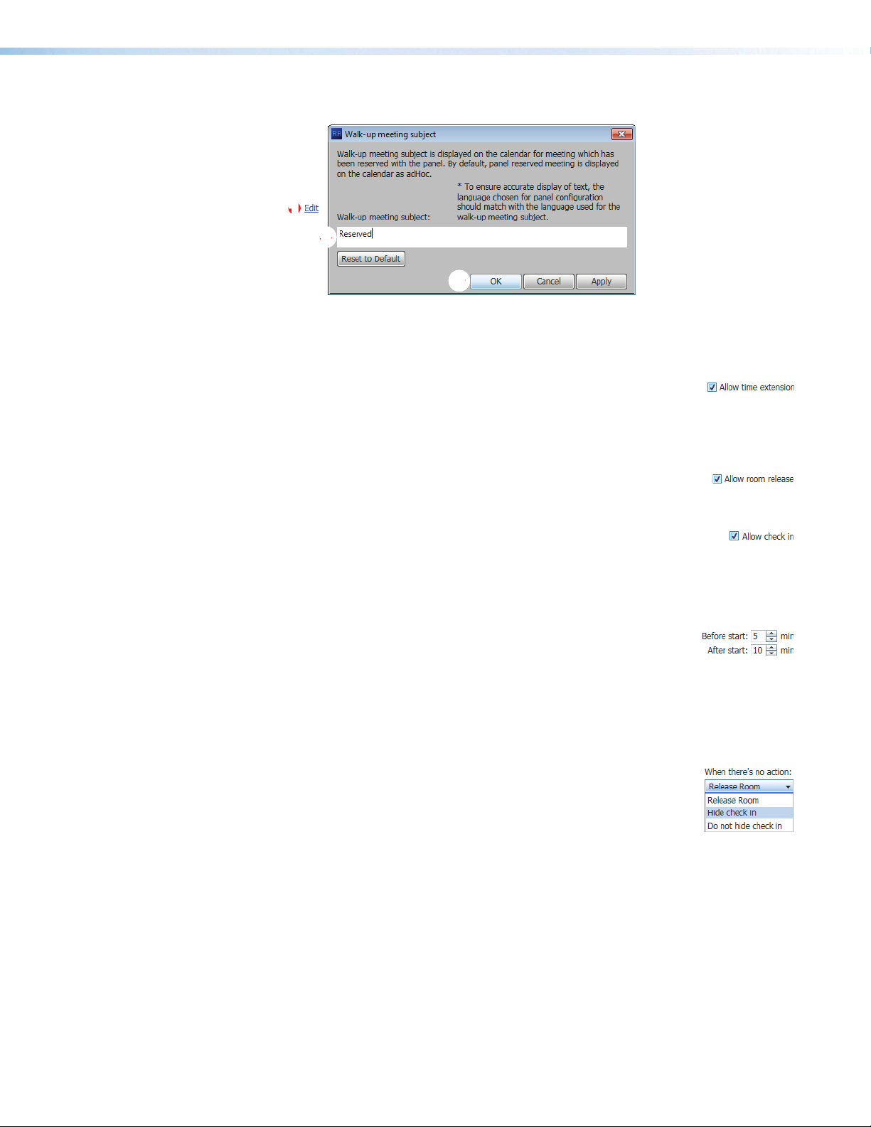
1. Click the Edit link (see figure 40, 1).
1111111111
22
22222222
33333333
33
Figure 40. Walk-up Meeting Subject Dialog Box
2. Type the new subject name in the
3. Click OK (3).
Allow time extension checkbox — Check and uncheck this
Ý
box to select whether the Extend until button appears on the
panel. Extend until extends the reservation of a room in half-hour increments IF
no previously scheduled reservation exists in the extension period. The Extend
until button does not appear if there is a conflict.
Allow room release checkbox — Check and uncheck this box to
4
select whether the Release button appears on the panel. Release
frees up a room, for example if the meeting ends early.
Allow check in checkbox — Check and uncheck this box to select
5
whether the Check in button appears on the panel for a scheduled
meeting. Check in disappears from a panel once it is pressed.
If checked, additional controls (ê and ë) appear on the panel to control how the
Check in button functions.
Before start and After start fields — Use the scroll buttons or
ê
type a value into these fields to define how long the Check in
button appears.
• Before start: controls how many minutes the Check in button displays
before the scheduled start of a meeting.
• After start: controls how many minutes the Check in button appears after
the scheduled start of the meeting.
When there’s no action drop-down list — Select among the
ë
options to choose how the Check in button and room reservation
behave when no action is taken.
• Release room — The scheduling software releases the room
when the After start: time has expired.
• Hide check in — The scheduling software hides the Check in button on the
panel and releases the room when the After start: time has expired.
• Do not hide check in — The panel continues to display the Check in button
until it is pressed.
Walk-up meeting subject: field (
2
).
Room Scheduling System • Room Agent Installation and Configuration 39
Page 46

4444444444
11111111
11
22222222
22
33333333
33
Background tab
If necessary, click the Background tab (see figure 41, 1) to make changes to the following:
• The color theme (dark or light) of the panel display:
• Any background image
• The opacity of any background image
Figure 41. Panel Design Pane, Background Tab and Preview Pane
Theme color: drop-down list — Use this drop-down list to
2
select either Light (black text on a light background) or Dark (white
text on a dark background).
Background image: —
3
• Change Image... button — Click to open a dialog box to assign a background
image (see figure 42 and the following procedure).
• Remove button — Click to clear any assigned background image.
1111111111
11111111
11
22222222
22
Figure 42. Open Dialog Box and Assign a Background Image
Room Scheduling System • Room Agent Installation and Configuration 40
Page 47
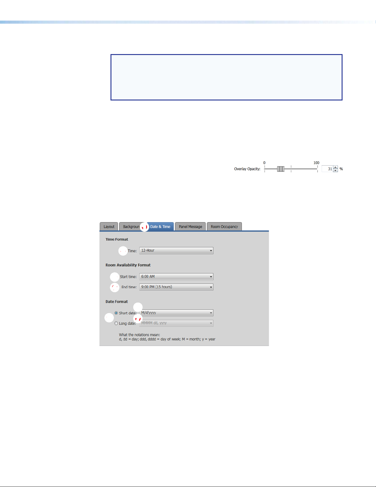
Assign or change a background image as follows:
NOTE: Room Agent software and the scheduling system support image files with
the following traits only:
•
JPEG or PNG format
800x480 r
•
8-bit color
•
1. Click the Change Image... button (see figure 41, 3 on the previous page). The
Open dialog box opens.
2. Navigate to the folder where you saved the background image file. Select the file
(see figure 42, 1 on the previous page).
3. Click Open (2). The Open dialog box closes and the newly assigned background
image is displayed in the preview pane (see figure 41).
Overlay Opacity (see figure 41) —Click
4
and drag this fader control or type a value
directly in the field to set the opacity of any displayed background image.
Date & Time tab
If necessary, click the Date & Time tab (see figure 43, 1) to make changes to the date and
time format.
esolution
11111111
11
22222222
22
33
33333333
44
44444444
66
66666666
5555555555
Figure 43. Panel Design Pane, Date & Time Tab
Time Format, Time: drop-down list — Use this drop-down list to select among
2
12-Hour (1:30 PM, for example), 24-Hour US (13:30),and 24-Hour International
(13.30).
Room Availability Format, Start time: drop-down list — Use this drop-down list to
3
select the start time of room availability display, in half-hour increments.
Room Availability Format, End time: drop-down list — Use this drop-down list to
4
select the end time of room availability display, in half-hour increments. The menu also
shows the quantity of time the room availability is displayed.
Date Format radio buttons — Use these radio buttons to select the format to display
5
on the panel. After you select either Short date or Long date, the associated dropdown list (see
77777777
77
and 7 on the next page) becomes available for selection.
6
Room Scheduling System • Room Agent Installation and Configuration 41
Page 48

Short date: drop-down list — Use this drop-down list, available when the Short
2222222222
33
333333334
6
date radio button is selected, to select among short date (in which the month is
represented by a numeral) display formats.
Long date: drop-down list — Use this drop-down list, available when the Long date
7
radio button is selected, to select among long date (in which the month is spelled out)
display formats, such as day month year or month day year and whether to include the
day of the week.
Panel Message tab
If necessary, click the Panel Message tab (see figure 44, 1) to make changes to the
message displayed when the panel has no connection to the calendar server.
1111111111
444444444
Figure 44. Panel Design Pane, Panel Message Tab
Panel message: field — Type in the panel message to be displayed.
2
Reset to Default button — Click to return the default panel message (displayed in
3
figure 44).
Clear All button — Click to clear the panel message.
4
Room Scheduling System • Room Agent Installation and Configuration 42
Page 49

Room Occupancy tab
2222222222
NOTES:
•
This scr
TLS 725M, and TLS 1025M scheduling panels, and TLP Pro 520M touchpanels
have the digital I/O connectors necessary to connect the OCS 100 Occupancy
Sensors.
•
See
the occupancy sensors to compatible panels.
een is always selectable and behaves as described, but only TLS 520M,
Occupancy Sensor Configuration on page 63 for an overview of connecting
If necessary, click the
rooms equipped with occupancy sensors.
Room Occupancy tab (see figure 45,
) to access the settings for
1
1111111111
ÕÕÕÕÕÕÕÕÕÕ
ÖÖÖÖÖÖÖÖ
ÖÖ
××
××××××××
33333333
33
Figure 45. Panel Design Pane, Room Occupancy Tab
Allow room occupancy sensor for meeting checkbox — Check and uncheck this
2
box to enable and disable the use of room occupancy sensors to determine if a meeting
has started.
If checked, additional controls (see Õ through ×) become available to control how the
sensors function.
Disable sensor field — Use the scroll buttons or type a value into this field to
Õ
disable the sensors for longer meetings.
When room is inactive field — Use the scroll buttons or type a value into this field
Ö
to set a time of room inactivity after the scheduled start time, after which the room
may be released for another meeting (as defined in ×). This field may not contain
0 minutes.
NOTE: This counter begins after the sensor has changed state to indicate the
room is unoccupied.
When room is inactive drop-down list — Use this drop-down list to select
×
between Take no action (leave the room reserved) and Release room (make the
room available for other users).
Room Scheduling System • Room Agent Installation and Configuration 43
Page 50

Sensor Output Type radio button (see figure 45 on the previous page) — Select one
2222222222
11
11111111
34
1111111111
3
of these radio buttons to denote how the occupancy sensor is wired to the TLS 520M,
TLS 725M, or TLS 1025M scheduling panel or TLP Pro 520M touchpanel:
• Control
•
Relay
- NC (Normally Closed)
•
Relay
- NO (Normally Open)
Preview pane
The preview pane (see figure 46, 1) shows the effects of changes that you make using the
controls within the panel design pane.
NOTE: The preview pane contains hardcoded, sample, entries. The layout and
appearance of this pane change to reflect your changes in the design pane, but,
other than the date and time, the content, such as “Main Conference Room”, do not
change.
Figure 46. Preview Pane and Drop-down list
Preview: drop-down list — The Preview:
2
drop-down list lets you select among various
display possibilities so that you can further refine the
appearance of panels in all of these circumstances.
Templates pane
Templates, such as the default DefaultTLPTemplate, which is the default that is installed
as part of the Room Agent installation, allow you to create a number of customized panel
appearances. Each panel in a system can have its own template, assigned on the Panel
Configuration window (see figure 21,
templates on the Templates pane (see figure 47).
333333333
2222222222
Figure 47. Templates Pane and Drop-down list
on page 22 for an example). Select the
7
444444444
Room Scheduling System • Room Agent Installation and Configuration 44
Page 51

• To assign the appearance of a displayed template to the panels, double-click a
42
23333333333
displayed template (1).
• To delete a template, click the (2).
• To add a new template:
• Type a name in the Panel Template: field (
• Click the Save button (
Show Available Network Adapters
Room Agent can show you all of the network interfaces available on the computer
for you to use in communications and allow you to select the active one. Type
<Ctrl>+<Shift>+<F2> to open a dialog box displaying the available controllers
(see figure 48).
1111111111
4
).
3
).
44
4444444
Figure 48. Available Network Controllers Dialog Box
Select a network controller as follows:
1. Click the desired controller (
2. Click OK (2).
To close the dialog box without selecting the controller, click Cancel (3). To refresh the
view, click Refresh (4).
1
).
22222222
Room Scheduling System • Room Agent Installation and Configuration 45
Page 52

Update Firmware
Room Agent reports Cannot connect to this device if the panel firmware version is:
• Older than 2.01.0000-b008
• TLP Pro touchpanel models only — Is the shipped-from-the-factory firmware
Update panel firmware for any reason as follows:
1. Click the Setup button for a panel to be updated.
(firmware for the panels as part of control systems.
NOTE: The latest firmware for all compatible panels is automatically downloaded onto
your PC when you install the Room Agent software. New versions of Room Agent
software may have new firmware that supports new features.
NOTE: Whenever you download a new version of Room Agent software, you should
update firmware to take advantage of the any new features the software provides.
NOTE: The button deletes a panel from the list.
The Panel Connection dialog box opens (see figure 49).
1111111111
22222222
22
Figure 49. Panel Connection Dialog Box
2. If applicable, enter a password in Password field (
NOTE: All panels ship with the default, case-sensitive, password “extron”.
3. Click the
NOTE: This step and this connection are necessary to send a firmware file to the
The Room Agent software connects to and synchronizes with the panel. Once synced,
Room Agent displays the Device Management window with either the Communication
Settings tab (see figure 15 on page 19) or General Settings tab (see figure 16 on
page 20) selected.
Connect button (
panel.
2
).
1
).
Room Scheduling System • Room Agent Installation and Configuration 46
Page 53
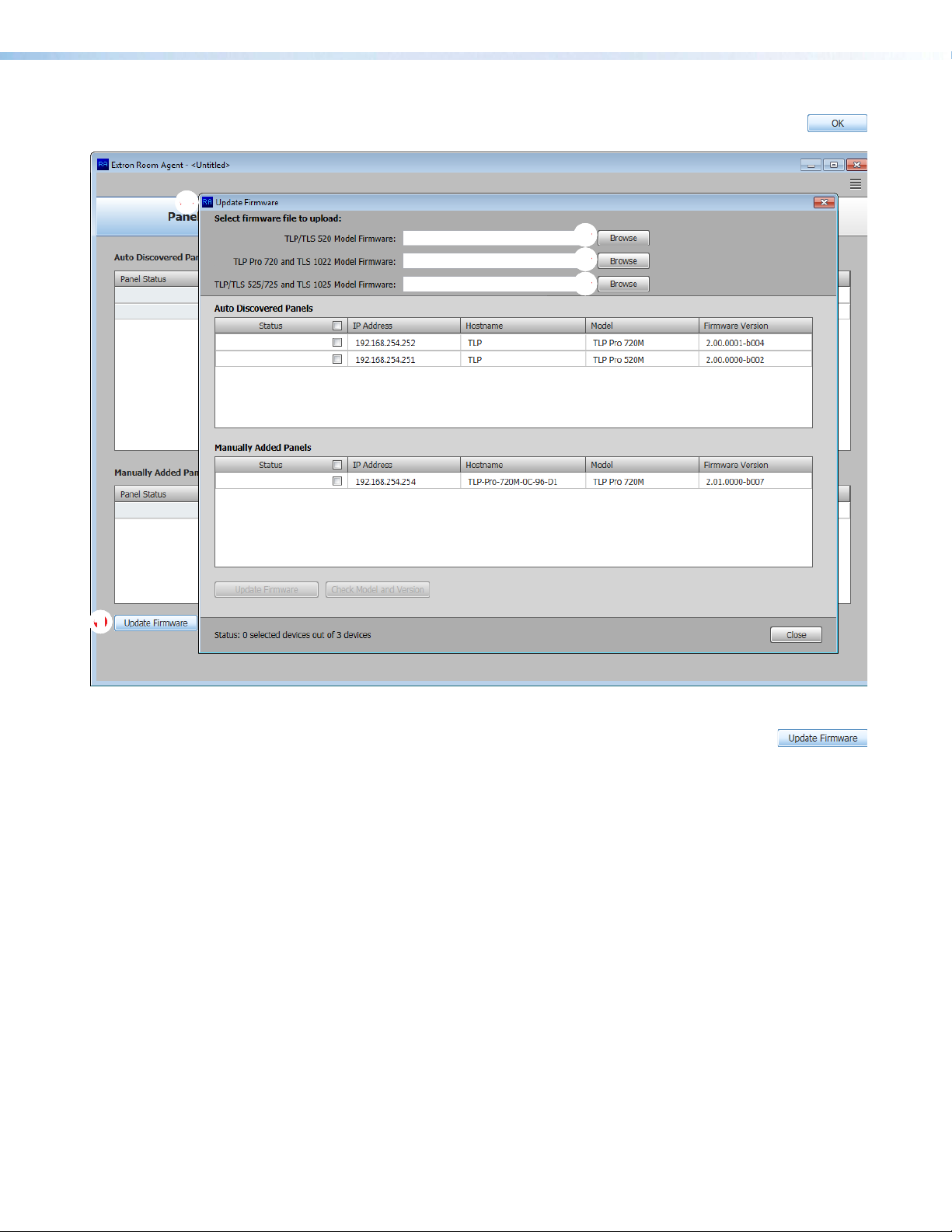
2222
2222222222
4. Click OK. The Device Management window closes and the Panel
Configuration window is displayed (see figure 50).
3333333333
3333
3333333333
3333
3333
3333333333
11111111111111
Figure 50. Firmware Update
5. Click the Update Firmware button (see figure 50,
Firmware window opens (
6. Click the Browse button for the desired model (3):
• TLP/TLS 520 Model Firmware
• TLP
• TLP/TLS
The Open Firmware File dialog box opens in the appropriate folder for the firmware
(see figure 51 on the next page).
Pro 720 and TLS 1022 Model Firmware
525/725 and TLS 1025 Model Firmware
2
).
). The Update
1
Room Scheduling System • Room Agent Installation and Configuration 47
Page 54

1111111111
Figure 51. Firmware File Selection
22222222
22
7. Select the file (see figure 51,
8. Click Open (2). The Update Firmware window returns to the top with the firmware file
selected (see figure 52, 1).
1
).
1111111111
22
22222222
22222222
22
44
44444444
33333333
33
44444444
44
55555555
55
Figure 52. Selecting Firmware Files and Panels
9. If desired, repeat steps 2 through 4, beginning on page 46 for other panel types. The
Update Firmware window returns to the top with the firmware file selected (
Room Scheduling System • Room Agent Installation and Configuration 48
2
).
Page 55

10. Select (click) one or more checkboxes for the panels that you want to update (see
figure 52, 3 and 4 on the previous page). Ensure that you have the correct firmware
file selected for the panels you select.
Once firmware files and panels are selected, the Update Firmware button becomes
available for selection (5).
11. Click the Update Firmware button (5). The Status column reports the status of the
update (see figure 53). When the Status is Updated, the update is complete.
Figure 53. Firmware Update Status Flow
12.
Click the Close button to return to the Panel Management view
(see figure 13 on page 17). Room Agent reports Panel Info
Updated in the Panel Status column.
Room Scheduling System • Room Agent Installation and Configuration 49
Page 56

Microsoft Environment Setup
This section provides guidance for an experienced IT person to set up the Room Scheduling
System in a Microsoft environment (Office 365 and Exchange). Topics include:
• Platform Versions
• Before You Begin
• Set up the Room Scheduling System in the Microsoft Environment
The Extron Room Scheduling System works within the Microsoft environment (Exchange
and Office 365) by tying compatible panels to room mailboxes. This tie allows Microsoft
Outlook users to view the availability of a room and reserve it. This section guides system
administrators through linking the Scheduling System to the Rooms.
Platform Versions
The Extron Room Scheduling System works with cloud-based Microsoft Office 365 as well
as the following Microsoft Exchange versions maintained on the premises of your facility:
• Exchange 2007, Service Pack 1
• Exchange 2010
• Exchange 2013
• Exchange 2016
In Exchange servers, the Room Scheduling System uses the Exchange Web Services (EWS)
protocol to tie in to the server room mailboxes; no plugins or additional software are required
on the server.
The Room Scheduling System subscribes to the room mailboxes. The EWS protocol
includes push notifications. The server pushes change notifications to the Room Scheduling
System whenever calendar changes occur.
Room Scheduling System • Microsoft Environment Setup 50
Page 57

Before You Begin
Complete all of the following steps before starting to set up the Room Scheduling System:
� Ensure all of the desired panels are installed in the appropriate locations (see Panel
�
�
Installation Overview, beginning on page 64).
e that all rooms are listed in the Exchange server (Exchange on premises) or
Ensur
Exchange online (Office 365).
Compile a list of the following for all panels designated as r
all rooms.
� Panel IP addr
The default address for all compatible panels is 192.168.254.251.
Visit www.extron.com and see the applicable panel user guides, to assign unique
IP addresses to each panel.
� Panel passwor
extron.” See the applicable manuals listed above to assign different passwords.
“
� Exchange User IDs — The Exchange User ID requires the User Principal Name
(UPN, the name of a Windows network user in an SMTP e-mail address format) for
the room resource user ID. The UPN must have an SMTP e-mail address assigned
to it.
• Abbreviated Exchange User IDs (aliases) will not work.
• See Verify the Exchange User ID is the UPN (Exchange) on page 52 or
Verify the Exchange User ID is the UPN (Office 365) on page 54 if you are
not certain that your Exchange User IDs are UPNs.
� Room passwords
esses — Each panel in the system requires a unique IP address.
ds — All panels ship with the default, case-sensitive, password
oom scheduling devices and
Room Scheduling System • Microsoft Environment Setup 51
Page 58

Verify the Exchange User ID is the UPN (Exchange)
NOTE: The guidelines in this section are intended for IT professionals only. Installers
or integrators attempting to follow these guidelines should do so only in close
coordination with the IT department of the organization where the Room Scheduling
System is to be installed.
Verify the UPN as follows:
1. Access the Exchange server Active Directory Users and Computers window
(see figure 54).
1111111111
Figure 54. Active Directory
2. Click the Find object ( ) icon (see figure 54,
Groups dialog box opens (see figure 55).
). The Find Users, Contacts, and
1
22
1111111111
33
333333334444444444
55
55555555
Figure 55. Find Users, Contacts, and Groups Dialog Box
22222222
3. Enter the name of the room to be verified in the
field (1).
4. Click Find Now (2). The Search results: pane displays the room (3).
5. <Right-click> the room in the Search results: pane (4) and click Properties (5).
Room Scheduling System • Microsoft Environment Setup 52
User, Contacts, and Groups Name
Page 59

The Properties dialog box opens (see figure 56).
11
11111111
2222222222
33333333
33
Figure 56. E-mail Address Displayed on the General Tab
6. If necessary, click the General tab (
displayed.
7. Note the room e-mail address shown (2). This value is the UPN, the value used as the
only valid Exchange User ID for this room in the Room Scheduling System.
8. Click Cancel to exit the display (3).
9. Repeat steps 3 through 8 for each desired room.
TIP: Write down the UPNs of all rooms for setting up the Room Scheduling
System.
). The general properties for the room are
1
Room Scheduling System • Microsoft Environment Setup 53
Page 60

Verify the Exchange User ID is the UPN (Office 365)
NOTES:
The guidelines in this section ar
•
or integrators attempting to follow these guidelines should do so only in close
coordination with the IT department of the organization where the Room Scheduling
System is to be installed.
This information is corr
•
Extron and may change.
Verify the UPN as follows:
Access the Of
1.
33
33333333
fice 365
ect as of June 2017. However, this site is not controlled by
Admin center page (see figure 57).
e intended for IT professionals only. Installers
22222222
22
1111111111
Figure 57. Active Directory
2. Click Resources > Rooms & equipment (see figure 57,
Equipment pane displays.
3. Enter the room name in the Room field (2) and type <Enter> on the keyboard. The
room information appears (3).
4. Click on the room information (3). The dialog box for the selected room opens (see
figure 58 on the next page).
). The Home > Rooms &
1
Room Scheduling System • Microsoft Environment Setup 54
Page 61

1111111111
22
22222222
Figure 58. Room Information Dialog Box
5.
Note the r
value used as the only valid Exchange User ID for this room in the Room Scheduling
System.
6. Click Close to exit the display (2).
7. Repeat steps 2 through 6 for each desired room.
TIP: Write down the UPNs of all rooms for setting up the Room Scheduling
oom e-mail address shown (see figure 58,
System.
). This value is the UPN, the
1
Set up the Room Scheduling System in the Microsoft Environment
Perform the following operations to set up the Room Scheduling System:
� Start the Room Agent software as an administrator (see Start the Program on
page 15).
� Discover any panels that are on the same subnet as the computer running Room Agent
software (see Automatically Discover Panels on page 16).
�
Manually add any panels fr
Room Agent software (see Manually Add Panels beginning on page 16).
� Perform the following for each panel in the system:
� Connect to the panel (see
� Verify or change settings (internet variables and password) on the Communication
Settings tab (see Communication Settings window on page 19).
om a different subnet than the computer that is running
Connect to the panel on page 18).
NOTE: If you change any settings but the Hostname, the panel disconnects
and you must rediscover or manually find it again. A better approach is to
set these values ahead of time using the on-screen menus of the panel (visit
www.extron.com and see the applicable panel user guides).
Room Scheduling System • Microsoft Environment Setup 55
Page 62

� Verify or change settings (panel appearance, time, and audio clicks) on the
General Settings tab (see General Settings window on page 20).
� Customize the appearance of your panels as desired. See the following:
• Layout tab on page 37
• Background tab on page 40
• Date and Time tab on page 41
• Panel Message tab on page 42
� Select the calendar server, Microsoft Exchange or Microsoft Office 365 (see Panel
Configuration Tab on page 21.
� If you selected Micr
software to connect with the panels through the Exchange server (see Exchange
configuration on page 22).
NOTE: For Microsoft Office 365, connection is made automatically through
the Office 365 server.
� Configure one or more panels (see Configure panels on page 23 [for Microsoft
Exchange] or Configure panels on page 28 [for Microsoft Office 365]).
NOTES:
• The two "Configure panels" procedures linked above are identical; you can refer
to either.
•
The IP Addr
add panels.
•
The only values that you must enter ar
Exchange User Password.
• The Panel Design menu includes the DefaultTLPTemplate, which is the
default that is installed as part of the Room Agent software, as well as any
templates that you have created and saved (see Templates pane on page 44).
osoft Exchange above, configure the Room Agent
ess and Hostname variables are set when you discover or manually
e the Exchange User ID and the
� Send the configuration to selected panels (see Send and retrieve the configuration
on page 35).
Room Scheduling System • Microsoft Environment Setup 56
Page 63

Google Calendar Environment Setup
This section provides guidance for an experienced IT person to set up the Room Scheduling
System in a Google Calendar environment. Topics include:
• Download the JSON File
• Set up the Room Scheduling System in the Google Environment
Download the JSON File
NOTE: The guidelines in this section are intended for IT professionals only. Installers
or integrators attempting to follow these guidelines should do so only in close
coordination with the IT department of the organization where the Room Scheduling
System is to be installed.
The Room Scheduling System integrates the Google Calendar of your organization into the
Room Scheduling System. To do this, you need to download the JSON file as follows:
NOTES:
The following pr
•
necessary administrative rights.
The scr
•
browser. Your screen images may appear different.
This information is corr
•
Extron and may change.
1. Open a browser on the computer where Room Agent is installed.
Log into your Google account.
2.
3. Access the Google Developers Console for a Google Calendar API (https://console.
developers.google.com/flows/enableapi?apiid=calendar).
4. From the
The Google Calendar API show the
5.
Click Go to
page).
een images in this procedure were created using the Google Chrome™
drop-down list , select
Credentials
ocedure assumes that you already have a Google account with the
ect as of June 2017; however, this site is not controlled by
Create a Project
Go to Credentials
. The
Credentials
and click
button.
page opens
Continue
(see figure 59 on the next
.
Room Scheduling System • Google Calendar Environment Setup 57
Page 64
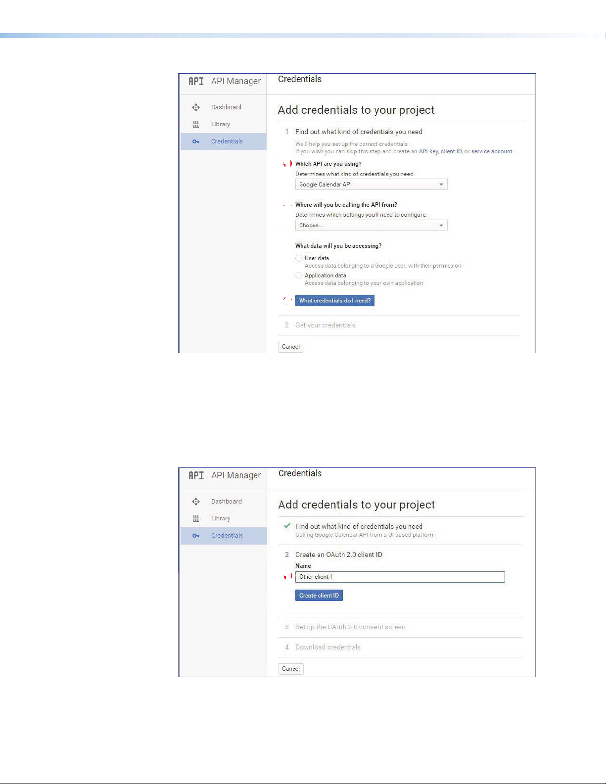
1111111111
22
22222222
33333333
33
44444444
44
Figure 59. Determine Credentials Needed
6. From the
7. From the
(e.g. Windows, CLI tool)
8. From the
9. Click
figure 60).
Which API are you using?
Where will you be calling the API from?
(2).
What data will you be accessing?
What Credentials do I need
drop-down list, select
drop-down list, select
(4). The
Add Credentials
Calendar API
drop-down list, select
User data
page opens (see
(1).
Other UI
(3).
1111111111
Figure 60. Add Credentials
Room Scheduling System • Google Calendar Environment Setup 58
Page 65
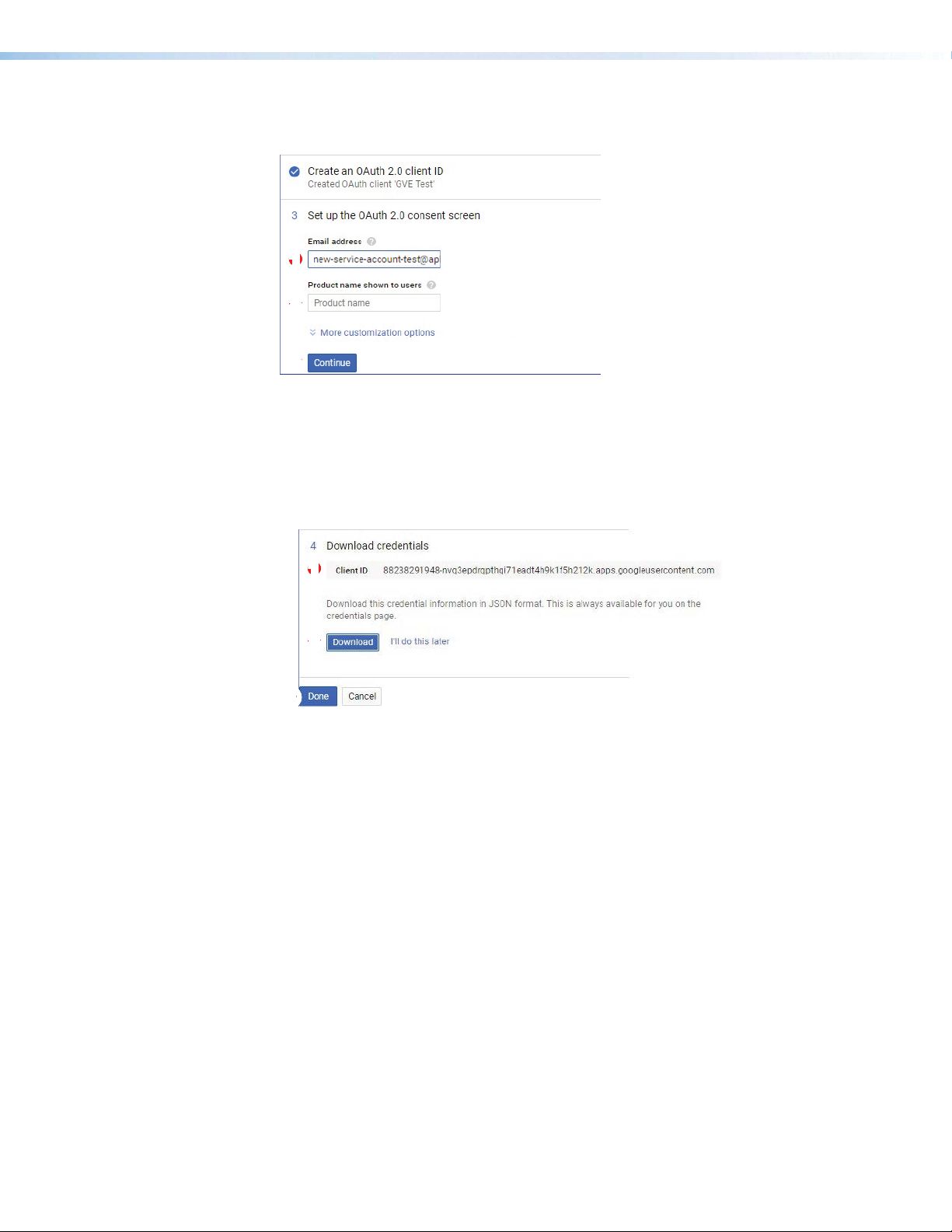
10. Enter a name and click
3333333333
The
OAuth 2.0 Consent
Create Client ID
fields open (see figure 61).
(see figure 60, 1, on the previous page).
1111111111
22222222
22
33
33333333
Figure 61. Set up OAuth fields
11.
Enter the
Enter a
12.
Device page during the Google Calendar setup (see step 9 on page 31).
13. Click
(see figure 62, 1).
Email address
Product Name shown to users
Continue
(3). Your Client ID is shown in the Download credentials area
used to access the Google Calendar (1).
(2). This name appears on the Google
1111111111
22222222
22
Figure 62. Download JSON file
14. Click
15. Click
Download
device during configuration (see Google Calendar configuration on page 29).
Done
(2) to save the JSON file. This file is required to authenticate the
(3).
Room Scheduling System • Google Calendar Environment Setup 59
Page 66
Set up the Room Scheduling System in the Google Environment
Perform the following operations to set up the Room Scheduling System:
� Start the Room Agent software as an administrator (see Start the Program on
page 15).
�
Discover any panels that ar
software (see Automatically Discover Panels on page 16).
�
Manually add any panels fr
Room Agent software (see Manually Add Panels beginning on page 16).
Perform the following for
�
� Connect to the panel (see
erify or change settings (internet variables and password) on the Communication
� V
Settings tab (see Communication Settings window on page 19).
NOTE: If you change any settings but the Hostname, the panel disconnects
and you must rediscover or manually find it again. A better approach is to
set these values ahead of time using the on-screen menus of the panel (visit
www.extron.com and see the applicable panel user guides).
� V
erify or change settings (panel appearance, time, and audio clicks) on the
General Settings tab (see General Settings window on page 20).
Customize the appearance of your panels as desir
�
• Layout tab on page 37
• Background tab on page 40
• Date and Time tab on page 41
• Panel Message tab on page 42
� Select the Google Calendar server, (see Panel Configuration Tab on page 21).
� Configur
Calendar server (see Google Calendar configuration on page 29).
Configur
�
� Authenticate the device to Google (identify the JSON cr
� Enter a valid Google account name.
e the Room Agent software to connect with the panels through the
e one or more panels (see Configure panels on page 29).
e on the same subnet as the computer running Room Agent
om a different subnet than the computer that is running
each panel in the system:
Connect to the panel on page 18).
ed. See the following:
edentials).
NOTES:
•
The IP Addr
add panels.
•
The Room Agent softwar
File to the end of the Google Account and displays the new value in the
Google Account field
• The
� Send the configuration to selected panels (see Send and retrieve the configuration
on page 35).
Panel Design menu includes the DefaultTLPTemplate, which is the
default that is installed as part of the Room Agent software, as well as any
templates that you have created and saved (see Templates pane on page 44).
ess and Hostname variables are set when you discover or manually
e appends the name of the
Room Scheduling System • Google Calendar Environment Setup 60
Import Credential JSON
Page 67

Reference Information
This section provides a central location for additional Room Scheduling System information,
including:
• System Communications Overview
• Supported Languages
• Occupancy Sensor Configuration
•
Panel Installation Overview
System Communications Overview
The following table is a summary of ports and protocols used by the Extron Room
Scheduling System.
Port Protocol Service Description
80 TCP HTTP Used by panel and redirects to TCP port 443
123 UDP NTP Used by panel for NTP Service
443 TCP HTTPS Bidirectional communication between the panel and
4502 UDP Discovery Used by Room Agent software to discover panels
4503 TCP SSH Internal system messaging between the panel and
4522 TCP SFTP Initiated from the Room Agent software; used
5353 UDP mDNS Multicast DNS
the calendar server
on the local subnet
the Room Agent software
when retrieving an activity file from the panel and
upgrading firmware
Room Scheduling System • Reference Information 61
Page 68
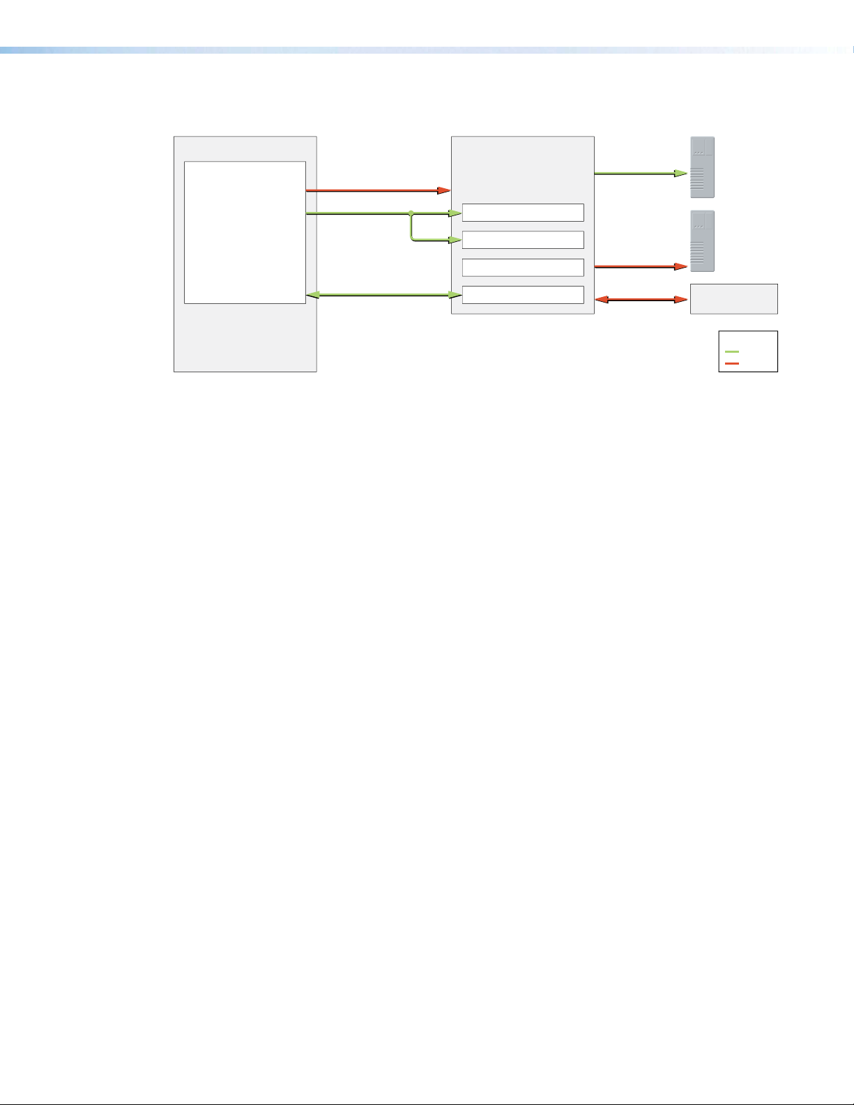
Figure 63 diagrams the general communications flow for the Extron Room Scheduling
System.
Windows PC / Laptop
Room Agent Software
Room Agent software is only used during
setup and conguration of TouchLink
Scheduling Panels
Figure 63. Room Scheduling Communication Flow Diagram
Supported Languages
As of Room Agent software release 1.3.0, the software supports scheduling panel displays
in the following languages:
4502
4522
4503
TouchLink Scheduling Panel
Activity File
Firmware Update
NTP Service
Internal System Messaging
80/443
123
5353
Calendar Server
NTP Server
Multicast DNS (mDNS)
Legend
TCP
UDP
•
English • Arabic • Chinese
(simplified)
•
Chinese
•
oatian
Cr
(traditional)
• Czech • Danish • Dutch • Finnish • French
•
German • Hebr
ew •
Italian • Japanese • Kor
ean
• Norwegian • Polish • Portuguese • Russian • Serbian
•
Slovenian • Spanish • Swedish • Thai • T
• Vietnamese
urkish
Room Scheduling System • Reference Information 62
Page 69
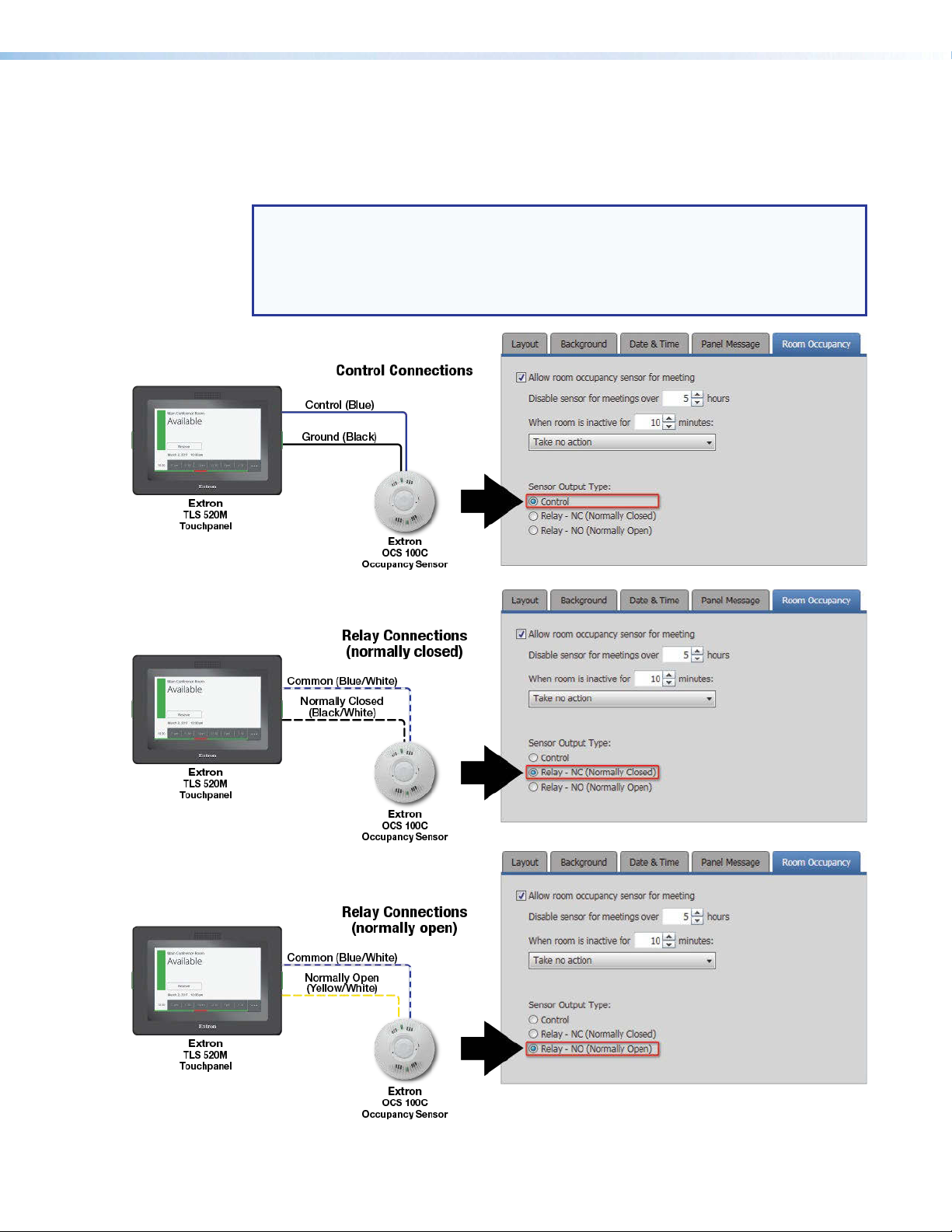
Occupancy Sensor Configuration
TLS 520M, TLS 525M, TLP Pro 520M, TLS 725M, and TLS 1025M panels have digital I/O
connectors necessary to connect room occupancy sensors. Figure 64 shows how to wire
the sensors to the panels and configure the panels.
NOTES:
•
•
e 64 shows the Extron OCS 100C (ceiling) Occupancy Sensors. OCS 100W
Figur
(wall) sensors are wired identically. If you use other sensors, check the connections
and wiring in the documentation for your sensors.
e 64 is a configuration drawing only and does not show power to the sensors.
Figur
Figure 64. Occupancy Sensor Connection and Panel Configuration
Room Scheduling System • Reference Information 63
Page 70

Panel Installation Overview
The Extron panel models have the following mounting capabilities:
• TLS 520M and TLP Pro 520M Panels —
• Mountable in a wall
• Mountable on a non-porous surface, such as a conference room window with the
• TLS 525M Scheduling Panel —
• Mountable in a wall with an optional RWM 1 Recessed Wall Mount Kit
• Mountable on a non-porous surface, such as a conference room window with the
• TLS 725M Scheduling Panel —
• Mountable in a wall with the optional RWM 2 Recessed Wall Mount Kit.
• Mounted on a non-porous surface, such as a conference room window with the
• TLS 1022M AND TLP Pro 720M Panels — Mountable in a wall
• TLS 1022T AND TLP Pro 720T Panels — Mountable to a two-gang, UL-certified
junction box; a two-gang mud ring; or directly into or onto any solid surface, such as
brick, wood, masonry, or drywall (with an optional Extron LPVM-1 Low Profile VESA
Mount)
• TLS 1025M Scheduling Panel —
• Mountable in a wall with the optional RWM 2 Recessed Wall Mount Kit.
• Mounted on a non-porous surface, such as a conference room window with the
All panels can receive power and communication over a single Ethernet cable. Power over
Ethernet (PoE) eliminates the need for a local power supply. PoE requires a PoE injector,
which is sold separately.
ATTENTION:
•
•
optional Extron SMB 1 Low Profile Surface Mount Box and GMK 1 Glass Mount Kit
optional Extron SMK 1 Surface Mount Kit
optional Extron SMK 2 Low Profile Surface Mount Kit
optional Extron SMK 3 Low Profile Surface Mount Kit
The following guidelines ar
instructions and safety guidelines, visit www.extron.com and see the applicable
panel user guides.
Les consignes suivantes n’of
consignes complètes d’installation et de sécurité des écrans tactiles, consultez les
manuels d’installation pertinents sur www.extron.com.
e overviews only. For complete panel installation
frent qu’une description succincte. Pour accéder aux
Room Scheduling System • Reference Information 64
Page 71

Wall Mounting
Mount the panel directly into drywall as follows:
ATTENTION:
�
�
� Use the cut-out template (available from www.extron.com) to mark the wall at a
�
�
�
�
Do not install the panel in a fir
•
• Veuillez ne pas installer les écrans tactiles dans un mur protégé par un dispositif
coupe-feu ou dans une cloison.
• All structural steps and electrical installation must be performed by qualified
personnel in accordance with local and national building codes and electrical
codes.
• Toute étape structurelle et installation électrique, doit être effectuée par un
personnel qualifié, conformément aux codes du bâtiment, aux codes incendie et
sécurité, et aux codes électriques, locaux et nationaux.
(TLS 525M)
(TLS 725M)
suitable location.
Use a drywall saw or jigsaw to cut away the hole.
Route the cables, leaving enough slack to connect them to the back of the panel.
Plug the cables into the r
Install the panel.
Obtain an optional Extron RWM 1 Recessed Wall Mount Kit.
Obtain an optional Extron RWM 2 Recessed Wall Mount Kit.
ear panel connectors.
e resistant rated wall or partition assembly.
Window Mounting (TLS 520M, TLS 525M, TLS 725M, TLP Pro 520M, and TLS 1025M)
Mount the panel to a conference room window or other non-porous surface as follows:
� (TLS 520M, TLP Pro 520M) Obtain an optional Extron SMB 1 Low Profile Surface
Mount Box and a GMK 1 Glass Mount Kit.
� (TLS 525M) Obtain an optional Extron SMK 1 Low Profile Surface Mount Kit.
�
(TLS 725M)
�
(TLS 1025M)
�
Decide wher
� Affix the adhesive patch included with the glass mount kit.
� Affix the glass mount kit plate to the adhesive patch.
�
Mount the surface mount box to the glass mount kit.
NOTE: If required, drill a hole in the side of the surface mount box to run cables and
raceway from the side of the mounting kit.
� (TLS 520M, TLP Pro 520M) Secure the surface mount box to the glass mount kit.
� Secure the wallplate adapter to the surface mount kit.
� Run cables through the cable cutout and connect them to the back panel of the panel.
NOTE: If required, mount an adhesive raceway (not provided) to run the cables.
Obtain an optional Extron SMK 2 Low Profile Surface Mount Kit.
Obtain an optional Extron SMK 3 Low Profile Surface Mount Kit.
e to place the panel and clean the glass surface.
� Press the panel onto the wallplate adapter. Four catches hold it in place.
Room Scheduling System • Reference Information 65
Page 72

VESA Mounting (TLS 1022T, TLP Pro 720T)
� Remove the back and base covers from the panel.
�
If necessary
the cables.
�
Remove the four spanner drive security scr
�
Lift the panel away fr
�
If necessary
panel.
� Secure a VESA D 75 mm mount kit to the back of the panel. Follow the instructions
provided with the mounting kit.
, cut the zip tie holding the twisted pair cables to the panel base and remove
om the base.
, connect the cables and use a zip tie to secure them to the back of the
ews holding the hinges to the panel.
Room Scheduling System • Reference Information 66
Page 73

Extron Warranty
Extron Electronics warrants this product against defects in materials and workmanship for a period of three years
from the date of purchase. In the event of malfunction during the warranty period attributable directly to faulty
workmanship and/or materials, Extron Electronics will, at its option, repair or replace said products or components,
to whatever extent it shall deem necessary to restore said product to proper operating condition, provided that it is
returned within the warranty period, with proof of purchase and description of malfunction to:
USA, Canada, South America,
and Central America:
Extron Electronics
1230 South Lewis Street
Anaheim, CA 92805
U.S.A.
Europe and Africa:
Extron Europe
Hanzeboulevard 10
3825 PH Amersfoort
The Netherlands
Asia:
Extron Asia Pte Ltd
135 Joo Seng Road, #04-01
PM Industrial Bldg.
Singapore 368363
Singapore
This Limited Warranty does not apply if the fault has been caused by misuse, improper handling care, electrical
or mechanical abuse, abnormal operating conditions, or if modifications were made to the product that were not
authorized by Extron.
Japan:
Extron Electronics, Japan
Kyodo Building, 16 Ichibancho
Chiyoda-ku, Tokyo 102-0082
Japan
China:
Extron China
686 Ronghua Road
Songjiang District
Shanghai 201611
China
Middle East:
Extron Middle East
Dubai Airport Free Zone
F13, PO Box 293666
United Arab Emirates, Dubai
NOTE: If a product is defective, please call Extron and ask for an Application Engineer to receive an RA (Return
Authorization) number. This will begin the repair process.
USA: 714.491.1500 or 800.633.9876 Europe: 31.33.453.4040
Asia: 65.6383.4400 Japan: 81.3.3511.7655
Units must be returned insured, with shipping charges prepaid. If not insured, you assume the risk of loss or damage
during shipment. Returned units must include the serial number and a description of the problem, as well as the
name of the person to contact in case there are any questions.
Extron Electronics makes no further warranties either expressed or implied with respect to the product and its quality,
performance, merchantability, or fitness for any particular use. In no event will Extron Electronics be liable for direct,
indirect, or consequential damages resulting from any defect in this product even if Extron Electronics has been
advised of such damage.
Please note that laws vary from state to state and country to country, and that some provisions of this warranty may
not apply to you.
Worldwide Headquarters: Extron USA West, 1025 E. Ball Road, Anaheim, CA 92905, 800.633.9876
 Loading...