

Page 1

Product Category
Pass-thru AAPs
TLP Pro 720C • Setup Guide
Overview
The Extron TLP Pro 720C is a 7 inch Cable Cubby touchpanel with a ip-up, 800x480 LCD touchscreen with 18-bit color depth.
It is ideal for any AV application requiring a full-size, Cable Cubby touchpanel with a customizable interface. This guide provides
instructions for experienced installers to mount and install a TLPPro 720C touchpanel. For more complete instructions, see the
TLPPro 720C User Guide, at www.extron.com.
Setup Checklist
Get Ready
Download and install the latest version of the following software:
Global Configurator Professional or Global Configurator Plus — for setting up and conguring the control processor and
touchpanel.
GUI Designer — for designing layouts for Extron TouchLink
Both software programs are available from www.extron.com.
Obtain the following network information from your network administrator:
DHCP status (on or off). If DHCP is off, you will also require
IP address Subnet mask Gateway
®
Pro touchpanels and third party touch interfaces.
User name — by default these are either admin or user.
Passwords — by default these are either extron (for admin) or the eld is left blank (for user).
Make a note of the touchpanel MAC address.
Make sure you are familiar with all the included parts and have all the necessary tools (see page 2) for installing the cable
cubby.
Included Parts
Table Clamps
With Power
Module
Without Power
Module
AC Power Module*
AC Power Module* 1 0
†
Pass-through AAPs
Blank AAPs 6 6
3 3
TLP Pro 720C
Zip Ties
Extron
Removal Tool
1-position bracket kit 0 1
2-position bracket kit 3 4
3-position bracket kit 1 1
NOTES:
* Inside the US, the TLP Pro 720C can be purchased with or without an AC power module. Outside the US, see
www.extron.com to nd an AC power module for your country.
†
Active or Passive AAPs must be purchased separately (see www.extron.com).
Blank AAPs
AAP Shelf Bracket Kits
Extron
Extron
2 Pos
(2 brackets/kit)
#4−40 Screws
and Nuts
3 Pos1 Pos
1
Page 2

TLP Pro 720C • Setup Guide (Continued)
Tools Required for Installation
Safety Glasses
Vacuum Cleaner
Square
Tape Measure
Marking Pen
Phillips Screw Driver
1/4" Hex Nut Driver
Mount and Cable All Devices
ATTENTION: Do not power on the touchpanels or control processors until you have read the Attention in the Power Supply
section of the TLP Pro 720C User Guide or the IPL Pro User Guide.
ATTENTION: Ne branchez pas les écrans tactiles ou les contrôleurs avant d’avoir lu la mise en garde dans la section
«sources d’alimentation» du TLP Pro 720C UserGuide ou du IPLProUserGuide.
Mount the units (see Mounting below).
Install power modules in the cable cubby.
Install AAPs and run cables to the cable cubby.
Connect cables to the touchpanels.
Connect the power cords and power on all devices.
Set up the Touchpanels for Network Communication
Connect the PC that you will use for setup, the control processor, and the touchpanel to the same Ethernet subnetwork.
Use the Setup Menu (see page 8) or the Toolbelt feature of Global Congurator Professional or Global Congurator Plus to
set the DHCP status and, if necessary, the IP address, subnet mask, gateway, and related settings for the touchpanel.
Configure the Touchpanels
The Global Configurator Professional Help File, the Global Configurator Plus Help File, and the GUI Designer Help File provide
step-by-step instructions and more detailed information. The Global Congurator Professional and Global Congurator Plus help
les include an introduction to the software and sections on how to start a project and conguration.
Mounting
Planning
Before making any cuts, select the best location for the TLPPro 720C.
Ensure that the edge that opens on the lid is oriented correctly.
Ensure there is enough space for all the system cables and components, including cable retractors, if they are to be installed.
Decide on the method for cutting a hole in the table:
z Hand router and template
z CNC wood router
z Jigsaw and paper template
Verify that you have the correct template or dimensions.
Check all relevant regulations.
z Ensure that the installation complies with local, state, and national building and electrical codes.
z Ensure that the installation complies with the Americans with Disabilities Act or other accessibility requirements.
2
Page 3
Product Category
P/N
P/
Step 1 — Obtain Cut-out Dimensions
ATTENTION:
• The opening in the table for the Cable Cubby should be cut only by licensed and bonded craftspeople. Exercise care
to prevent scarring or damaging the furniture.
• L’ouverture dans la table pour le CableCubby devrait être coupée seulement par des artisans autorisés et qualiés.
Faites attention à ne pas faire de marques sur le meuble et à ne pas l’endommager.
• Use the appropriate metal Extron routing template or refer to the surface cutout dimensions before cutting a hole in
the furniture or other surface. Pay special attention to the direction the unit will face. The connector access side is
underlined. Extron is not responsible for miscut mounting holes.
• Utilisez le gabarit de détourage métallique approprié ou reportez-vous aux dimensions de découpe de la surface
indiquées ci-après avant de découper le meuble ou la surface. Faites particulièrement attention à la directions dans
laquelle l’unité sera dirigée. Le côté pour accéder au connecteurs est souligné. Extron ne sera pas responsable des
erreurs de coupe.
• Ensure the table surface is at least 0.375 inches (0.95 cm) thick.
• Assurez vous que la surface de la table est au moins 0,95 cm (0,375") d’épaisseur.
If using a hand router, you should purchase the Extron TLP Pro 720C routing template.
If using a CNC wood router, use the exact cut-out dimensions (see Using a CNC wood cutter below).
If using a reciprocating saw or jigsaw use the paper cut-out template (available under the Downloads tab on the TLP Pro 720C
page at www.extron.com).
Step 2 — Cut the Surface
CAUTION: Risk of personal injury: Wear safety glasses when operating power equipment.
ATTENTION: Risque de blessure: Portez des lunettes de sécurité lorsque vous utilisez l’équipement électrique.
Be certain the cut is laid out in exactly the desired location and the edge that opens on the lid is correctly oriented. After verifying
and checking dimensions, cut a hole in the surface of the furniture where the enclosure will be installed (see “Preparing the Table”
in the TLP Pro 720C User Guide). There are three methods for cutting the hole in the table:
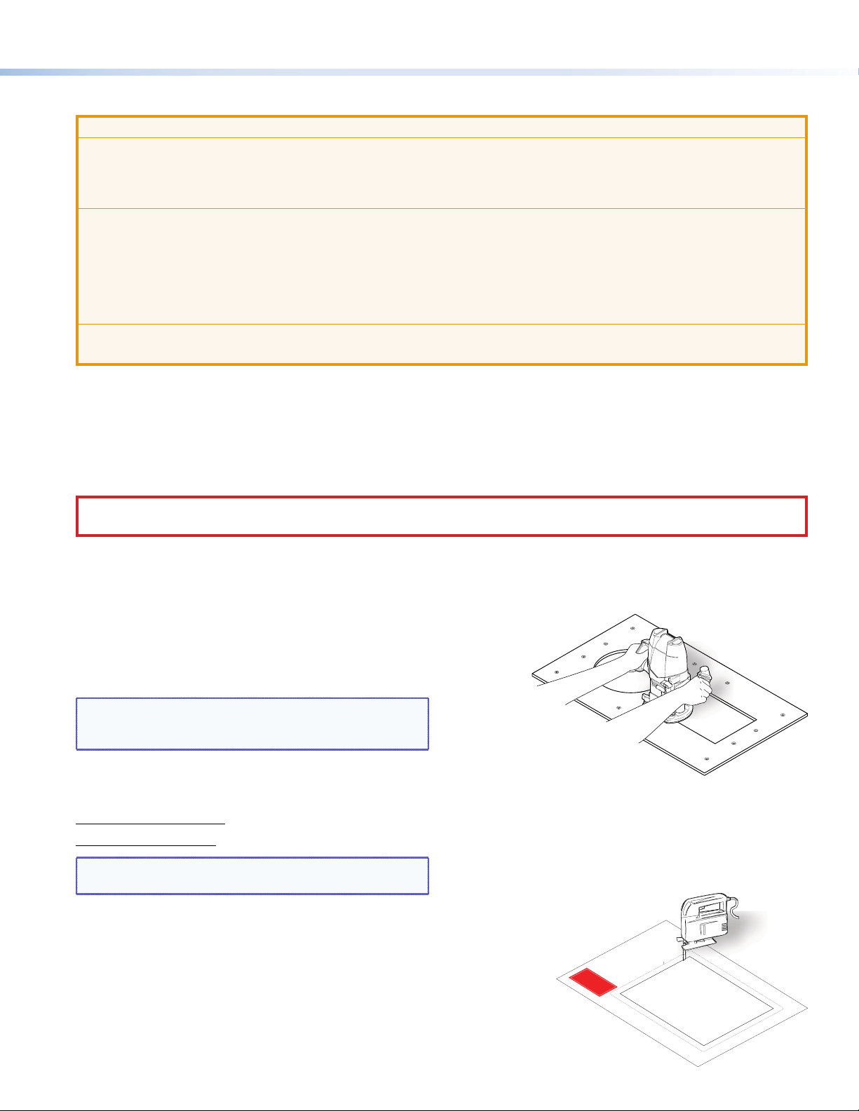
Using a hand router
Recommended method — Use the Extron TLP Pro 720C
routing template. Refer to the Routing Template User Guide,
available at www.extron.com, to prepare the template and
use the template to cut the hole.
NOTE: The metal router guide must be purchased
separately. It is reusable and should not be discarded
when the installation is complete.
Using a CNC wood cutter
Recommended method — Use the exact cut-out dimensions:
8.90 +0.00/-0.02 inches W x 7.10 +0.00/-0.02 inches D
(22.61 +0.00/-0.05 cm W x 18.03 +0.00/-0.05 cm D)
NOTE: The underlined dimension is the connector or AAP
access side for the unit.
CABLE CUBBY 300
HSA 200
USER ACCESS
HSA 200
CABLE CUBBY 300
USER ACCESS
Using a reciprocating saw or jigsaw
Acceptable method — Use the paper cut-out template (available
under the Downloads tab on the TLPPro 720C page at
www.extron.com).
1. Confirm the product to be installed.
Do not shrink.
Print scale 1:1
Page size: 11" x 17"
P/N 68-2046-01 Rev. B
(Do not cut this line.)
Outer Edge of Trim Ring
4. Cut the opening.
is being installed.
furniture where the TLP 710MV
3. Mark the position on the wall or
(gray) from the template.
2. Remove the surface cut-out area
TLP Pro 720C
Cut-Out Template for the Extron
3
Page 4

TLP Pro 720C • Setup Guide (Continued)
ts
Front Brackets
Secure the po
to the
with #4-40 Phillips head
scre
Extron
of mounting points
Step 3 — Run all Cables
Run all cables necessary to support the AC connector, the cables stored in the cubby, and all planned AAP connectors. Run the
cables below the table and through the hole that was cut in Step 2. Leave enough slack in the cables to connect or route them
before the cubby is installed in the table. Leave enough space under the enclosure for the external power supply and connection
of AV cables and the network connection for the TLPPro 720C.
Step 4 — Install Cable Retractors (Optional)
If required, Extron cable retractors should be installed in the enclosure at this stage. For complete information about retractors
and how to install them, see the Retractors User Guide, which is available from the Extron website (www.extron.com).
Step 5 — Install Power Module (Optional)
ATTENTION:
• For units that are used in North America, only
use AC power modules that are UL Listed Model
“Cable Cubby AC Power Module”.
•
• The unit is not UL Listed if it uses any AC power
module other than Model “Cable Cubby AC Power
Module”.
•
NOTE: For models that do not include a power module,
see the Extron website to select a power module that is
suitable for your location.
ws and star washers.
wer module
TLP Pro 720C frame
The power module takes up two or three AAP spaces, depending on
the model, and may be installed before or after the AAP assembly is installed. It may be installed with AAPs on either side.
1. Secure the power module into position with #4-40 Phillips head screws and star washers.
CAUTION: Risk of electric shock: To ensure proper electrical grounding, use the provided grounding screws and star
washers.
ATTENTION: Risque de choc électrique: An d’assurer une mise à la terre correcte, utilisez les xations de mise à la
terre et les rondelles en étoile fournies.
2. Run the cable or conduit to a convenient junction box. Extron recommends the circuit be attached to a junction box that is
directly wired to the main circuit.
Step 6 — AAP Assembly
Install all desired cables into the cable pass-through AAPs and
install the AAPs into the cable cubby.
The simplest way to install the cables and AAPs is to populate
the AAP brackets outside the cubby and then install the
populated AAP shelf assembly into the cubby.
Install cables in the pass-through holes as shown in the gure
to the right.
TIP: Hand tightening the #4-40 nuts makes it easier to
NOTE: An extra column of AAP bracket mounting points is
4
place and secure the assembly inside the enclosure.
available for use with TLP Single-space AAP mounting
brackets. Single-space brackets will not t in any other
location.
The extra column
is for installing
single-space
AAP brackets.
Rear Bracke
Page 5

Step 7 — Install the AAP Assembly
Phillips Head Scre
(secure AAP
assemb
ly through
1. From under the table, push the rst AAP assembly
through the bottom of the enclosure. The holes in the
rear bracket must align with the bottom row of holes on
the rear face of the enclosure.
TIP: Ensure there is enough space above the AAP
assembly for the lid to close completely without
cables or connectors contacting the touchpanel.
Product Category
Extron
2. Secure the AAP assembly into position with the
provided Phillips head screws.
3. Tighten the nuts that secure the AAPs to the brackets.
Step 8 — Mounting the Enclosure
Mount the cable cubby enclosure in the table.
CAUTION: The anged edges of the top of the surface enclosure are sharp. These edges are also soft and may be easily
nicked or bent. Exercise caution when handling the enclosure to prevent personal injury or damage to the enclosure.
ATTENTION: Les extrémités à brides du haut de la surface du boîtier sont aiguisées. Ces extrémités sont aussi lisses
et peuvent facilement être coupées ou pliées. Soyez prudents lorsque vous manipulez le boîtier an d’éviter de
l’endommager ou de vous blesser.
ws
ly)
2
Large slot
provides tool
access to fasten
rear brackets.
2
Push assemb
11
AUDIO
UTER
COMP
bottom of enclosure.
Tighten down
3
3
AAP nuts.
1. Remove the edge grommet protecting the edges of the trim ring
and the plastic lm on the nished surfaces.
ATTENTION: Do not use isopropyl alcohol or other solvents
to clean the Cable Cubby. Strong solvents will ruin some
nishes.
ATTENTION: Ne pas utiliser de l’alcool isoproprylique ou
d’autres solvants pour nettoyer le CableCubby. Les solvants
forts endommageront certaines nitions.
2. Carefully lower the enclosure into the hole cut in the table (see
Step2 — Cut the Surface on page 3). Ensure the trimring(5)
is ush with the top of the table.
3. Under the table, attach the table clamps (
each side of the enclosure. It may be necessary to loosen the
wingnuts (1) and the Phillips head screws (2).
4. When the clamps are properly seated on the pins, tighten the
Phillips head screws until the clamp faces (4) are tightly secured against the bottom of the table.
5. To prevent the screws from becoming loose, secure the wingnuts against the table clamp bodies.
) to the pins on
3
5
5
4
4
11
3
3
2
2
5
Page 6

TLP Pro 720C • Setup Guide (Continued)
Connecting the TLP Pro 720C
The cable connections are located in a panel on the bottom of the TLP Pro 720C:
AA
B
B
Power connector — Connect a 12 VDC, 1.0 A power supply (not provided) to this 2-pole, 3.5 mm captive screw connector.
A
ATTENTION: The TLP Pro 720C can use a 12 VDC desktop power supply and is also Power over Ethernet (PoE
802.3af, class3) compliant. Do not connect either power supply before reading the Attention in the Power Supply
section of the TLPPro720C User Guide.
ATTENTION: Le TLP Pro 720C peut utiliser une source d’alimentation externe 12 Vcc, et est également compatible
avec l’alimentation POE via Ethernet (PoE 802.3af, classe 3). Ne branchez pas de sources d’alimentation externes
avant d’avoir lu les mises en garde dans la section «PowerSupply» du TLPPro720C User Guide.
NOTES:
• The TLP Pro 720C ships without a power supply. Either the 12 VDC power supply or the PoE injector must be
purchased separately.
• If a 12 VDC and a PoE power supply are both connected to the TLP Pro 720C, the PoE injector takes precedence.
If a PoE power loss is detected, the touchpanel switches seamlessly to the 12 VDC supply without needing a
system reboot.
Network and Power over Ethernet (PoE) Connector — Connect the touchpanel to the LAN using a twisted pair cable,
B
terminated with an RJ-45 connector. The connector can also be used with a PoE power injector (not provided).
An Extron IP Link Pro control processor must also be connected to the same network as the TouchLink Pro touchpanel.
6
Page 7
Product Category
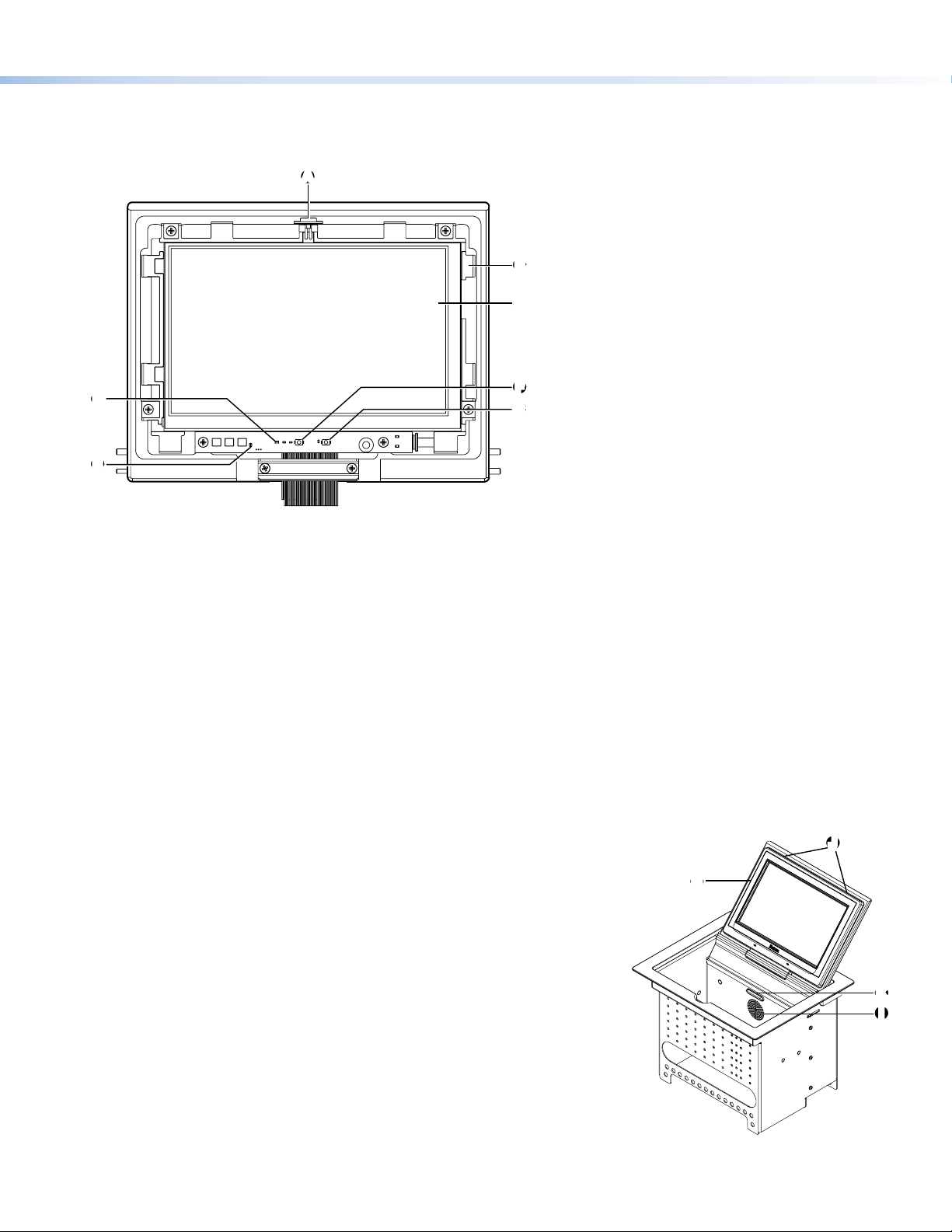
Front Panel Features
To see all the front panel features, remove the bezel, using the Extron Removal Tool. For a complete description of all these
features and their function, see the TLP Pro 720C User Guide.
AA
BB
C
C
F
D
D
F
G
G
EE
Ambient light sensor — monitors ambient light level and adjusts screen brightness, based on the settings congured using
A
the setup menu (see page 8).
Bezel attachment point — The TLP Pro 720C has eight attachment points (two on each side, two on the top edge, and two
B
on the bottom edge).
LCD screen — the TLP Pro 720C has a 7 inch screen with a 800x480 resolution
C
Reset LED— indicates power status and reset status of the device.
D
Communication LED — shows the conguration and connection status of the touchpanel:
E
z Unlit during normal operation (the touchpanel is congured and connected to an IP Link Pro control processor).
z Blinks red if the touchpanel has been congured but is not connected to an IP Link Pro control processor.
z Permanently lit if the touchpanel has not been congured and is not connected to an IP Link Pro control processor.
The indicator can be toggled between enabled and disabled, using the setup menu (see page 8).
Reset button — this button allows the unit to be reset. The TLP Pro 720C has three reset modes that are initiated by
F
pressing the reset button. For full information about these different modes, see the TLPPro 720C User Guide.
Menu button — activates the setup menu and calibration screen (see page8).
G
Bezel — use the included removal tool to detach the bezel.
H
Speaker — one, placed inside the cable cubby, provides audible feedback for
I
the user.
Bezel removal slots — allow removal of bezel, using Extron removal tool.
J
Illumination LED — provides light for cable cubby enclosure.
K
HH
J
J
K
K
I
I
7
Page 8

TLP Pro 720C • Setup Guide (Continued)
Setup Menu
The setup menu opens when the menu button is pressed (see Front
Panel Features, G on page 7). There are ve different screens: Status,
(shown in the gure to the right)
The screens can be selected by pressing the appropriate button in the
navigation bar at the top of the screen (for more information, see the
TLPPro 720C User Guide).
Press the menu button for at least 2 seconds to open the calibration
screen. Follow the on-screen instructions.
Network, Display, Audio, and Advanced.
Status
Model: TLP Pro 720C
Part Number: 60-1396-020A
Firmware
Version:
PoE Status:On
Network
Info
1.00
Display Audio Advanced Exit
Network
IP Address:
192.168.254.251
DHCP:
Off
Host Name:
TLP-AB-CD-EF
Audio
Master Volume:
Master Mute: Off
99
Display
Resolution:
Project:
Sleep Timer:
Advanced
Controller IP: N/A
Project Size: N/A
800x480
N/A
5 Minutes
Extron Headquarters
+1.800.633.9876 (Inside USA/Canada Only)
Extron USA - West Extron USA - East
+1.714.491.1500 +1.919.850.1000
+1.714.491.1517 FAX +1.919.850.1001 FAX
© 2014 Extron Electronics All rights reserved. All trademarks mentioned are the property of their respective owners. www.extron.com
8
Extron Europe
+800.3987.6673
(Inside Europe Only)
+31.33.453.4040
+31.33.453.4050 FAX
Extron Asia
+65.6383.4400
+65.6383.4664 FAX
Extron Japan
+81.3.3511.7655
+81.3.3511.7656 FAX
Extron China
+86.21.3760.1568
+86.21.3760.1566 FAX
Extron Middle East
+971.4.299.1800
+971.4.299.1880 FAX
Extron Korea
+82.2.3444.1571
+82.2.3444.1575 FAX
Extron India
1800.3070.3777
(Inside India Only)
+91.80.3055.3777
+91.80.3055.3737 FAX
68-2406-50 Rev. A
04 14
 Loading...