

Page 1
Product Category
TLP Pro 720T and TLP Pro 1020T • Setup Guide
Go to www.extron.com for the
complete user guide and installation
instructions before connecting the
product to the power source.
Overview
IMPORTANT:
The Extron TLP Pro 720T is a 7-inch tabletop touchpanel with a high resolution 800x480 LCD screen. The TLP Pro 1020T is
a 10-inch tabletop touchpanel with a high resolution 1024x600 LCD screen. They are ideal for any AV applications requiring
medium or large touchpanels with exible mounting options and fully customizable interfaces. This guide provides instructions for
experienced installers to mount and install a TLPPro 720T or TLP Pro 1020T touchpanel. For more complete instructions, see the
TLPPro 720 Series and TLPPro 1020 Series User Guide, at www.extron.com.
Setup Checklist
Get Ready
Download and install the latest version of the following software:
Global Configurator Professional or Global Configurator Plus — for setting up and conguring the control processor and
touchpanel.
GUI Designer — for designing layouts for Extron TouchLink® Pro touchpanels and third party touch interfaces.
Both software programs are available from www.extron.com.
Obtain the following network information from your network administrator:
DHCP status (on or off). If DHCP is off, you will also require
IP address Subnet mask Gateway
User name — by default these are either admin or user.
Passwords — by default these are either extron (for admin) or the eld is left blank (for user).
Make a note of the touchpanel MAC address.
Mount and Cable All Devices
ATTENTION:
• Do not power on the touchpanels or control processors until you have read the Attention in the Power Supply section
of the TLP Pro 720 Series and TLP Pro 1020 Series User Guide or the IPL Pro User Guide.
• Ne branchez pas les écrans tactiles ou les contrôleurs avant d’avoir lu la mise en garde dans la section «sources
d’alimentation» du TLP Pro 720 Series and TLP Pro 1020 Series UserGuide ou du IPLProUserGuide.
Mount the units. There are several mounting options for TouchLink Pro touchpanels (see Mounting on the following page).
Connect cables to the touchpanels.
Connect the power cords and power on all devices.
Set up the Touchpanels for Network Communication
Connect the PC that you will use for setup, the control processor, and touchpanel to the same Ethernet subnetwork.
Use the Setup Menu (see page 4) or the Toolbelt feature of Global Congurator Professional or Global Congurator Plus to
set the DHCP status and, if necessary, the IP address, subnet mask, gateway, and related settings for the touchpanel.
Configure the Touchpanels
The Global Configurator Professional Help File, the Global Configurator Plus Help File, and the GUI Designer Help File provide
step-by-step instructions and more detailed information. The Global Congurator Professional and Global Congurator Plus help
les include an introduction to the software and sections on how to start a project and conguration.
1
Page 2
TLP PRO 720T and TLP PRO 1020T • Setup Guide (Continued)
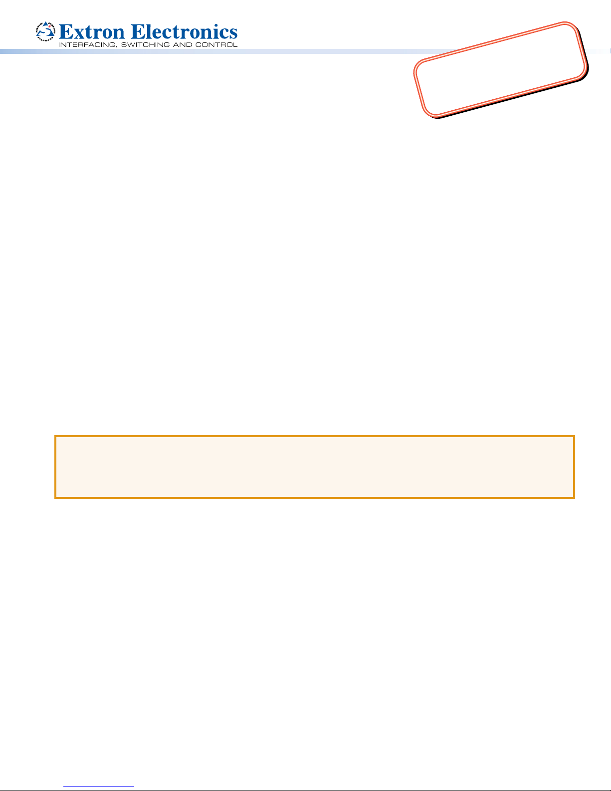
Kensington Security Slot
ve
Mounting Holes (2)
Locking Screw
Locking Plate
Mounting
The TLP Pro 720T and TLP Pro 1020T come assembled with stands that allow the units to be placed on any suitable surface.
A range of optional mounting kits are available for both the TLP Pro 720T and the TLP Pro 1020T. The kits must be purchased
separately. Follow the installation instructions provided with the kit.
Securing the Touchpanel with Screws
The bases of the units also have two mounting holes that allow the
units to be secured to the desktop. Figure 1 shows the base of the
TLPPro720T, but the TLP Pro 1020T is very similar.
1. Mark the location of two holes, 3.07inches (78 mm) apart.
This dimension is the same for both the TLP Pro 720T and the
TLPPro1020T.
2. Drill two holes through the desktop from underneath.
3. Attach the touchpanel, using two #8 wood screws through
the desktop from underneath into the two holes in the
base.
Kensington Security Lock
For added security, attach a Kensington Security Lock (not
provided) to the metal-reinforced slot on the rear edge of the
base. Figure 2 shows the rear edge of the TLP Pro 720T base,
but the TLP Pro 1020T base is very similar.
Follow the instructions that are provided by the manufacturer
to install the lock.
Figure 1. TLP Pro 720T Base to Show Mounting Holes
Figure 2. Slot for Kensington Security Lock
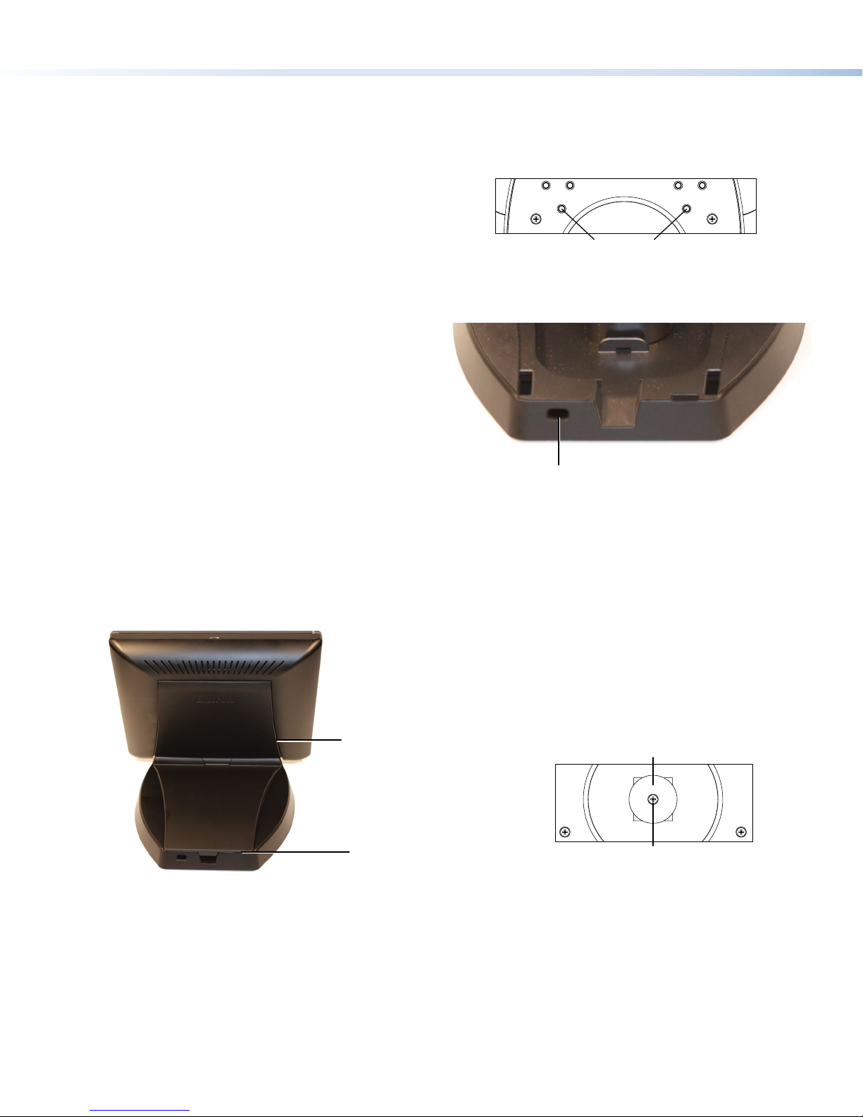
SMA-1 Swivel Mount Adapter
Both touchpanels can also be mounted with the optional Extron SMA-1 swivel mount adapter, which allows them to be mounted
permanently and swivel up to 180° in either direction.
1. Remove the back cover and base cover, using the provided Extron removal tool. There are two notches on each side of the
back cover and two notches on the back edge of the base cover. You must remove the back cover before you can remove
the base cover.
Notches to Remo
Back Cover (4)
Notch to Remove
Base Cover (2)
Figure 3.
Remove the Back and Base Covers
Figure 4. Locking Plate and Locking Screw
2. Remove the screw holding the locking plate at the bottom of the base. This releases the weight, which can be removed from
the top of the base, leaving the mounting hole that will t over the conduit of the SMA-1.
3. Attach the conduit, insulation disk, and swivel disk and congure the set screws to allow for the degree of swivel that is
required (see the SMA-1 Swivel Mount Adapter Kit User Guide, available at www.extron.com).
4. Place the mounting hole in the base over the conduit of the SMA-1.
5. Secure the unit with the backing plate and locking nut as described in the SMA-1 Swivel Mount Adapter Kit User Guide.
VESA mounting
Use an Extron LPVM-1 kit D-type with 75 x 75 mm mounting pattern. Follow the instructions provided with the kit.
2
Page 3

Front Panel Features
C
D
E
B
C
C
D
E
A
C
D
E
F
Product Category
F
C
D
A
E
B
Figure 5. TLP Pro 720T (left) and TLP Pro 1020T (right) Front Panels
Motion Sensor — detects motion between three to ve feet from the touchpanel, and at least 15° from the center axis.
A
z When no motion has been detected for a user-dened period of time, the touchpanel enters into sleep mode.
z When motion is detected by the sensor, the screen display is restored and active.
Speakers — the TLP Pro 720T has one, placed under the screen, on the left side of the panel. The TLP Pro 1020T has two,
B
placed under the screen, one on each side. They provide audible feedback for the user.
Status Lights — one on each top corner can be congured to provide system feedback.
C
z Light red or green
z Blink or light continuously
LCD screen — the TLP Pro 720T has a 7-inch screen with a 800x480 resolution. The TLP Pro 1020T has a 10-inch screen
D
with 1024x600 resolution.
Communication LED — shows the conguration and connection status of the touchpanel:
E
z Unlit during normal operation (the touchpanel is congured and connected to an IP Link Pro control processor).
z Blinks red if the touchpanel has been congured but is not connected to an IP Link Pro control processor.
z Permanently lit if the touchpanel has not been congured and is not connected to an IP Link Pro control processor.
The indicator can be toggled between enabled and disabled, using the setup menu (see page 4).
Ambient light sensor — monitors ambient light level and adjusts screen brightness, based on the settings congured using
F
the setup menu.
F
C
A
B
Rear Panel Features
TLP Pro 720T
N15779
I.T.E.
1T23
33-2455-01 A
Patent(s) www.extron.com/patents
POWER
12 V
1.0 A MAX
LAN / PoE
Figure 6. TLP Pro 720T (left) and TLP Pro 1020T (right) Rear Panels
Power Connector
A
Network and Power over Ethernet (PoE) Connector
B
Menu Button
C
B
F
A
B
TLP Pro 1020T
POWER
12 V
1.0 A MAX
Reset Button
D
Reset LED
E
VESA Mounting Holes
F
I.T.E.
1T23
Patent(s) www.extron.com/patents
LAN / PoE
N15779
33-2453-01 A
3
Page 4

TLP PRO 720T and TLP PRO 1020T • Setup Guide (Continued)
Power connector — connect a 12 VDC, 1.0 A power supply (not provided) to this DC plug connector.
A
ATTENTION:
• The TLP Pro 720T and TLP Pro 1020T can use a 12 VDC power supply and are also Power over Ethernet (PoE
802.3af, class 3) compliant. Do not connect either power supply before reading the Attention in the Power section
of the TLP Pro 720 Series and TLP Pro 1020 Series User Guide.
• Le TLP Pro 720T et le TLP Pro 1020T peut utiliser une source d’alimentation externe 12 Vcc, et est également
compatible avec l’alimentation POE via Ethernet (PoE 802.3af, classe 3). Ne branchez pas de sources
d’alimentation externes avant d’avoir lu les mises en garde dans la section «PowerSupply» du TLP Pro 720 and
TLPPro 1020 Series User Guide.
NOTES:
• The TLP Pro 720T and TLP Pro 1020T are shipped without a power supply. Either the 12 VDC, 1.0 A power supply
or the power injector must be purchased separately.
• If a 12 VDC and a PoE power injector are both connected to the TLP Pro 720T or TLP Pro 1020T, the power
injector takes precedence. If a PoE power loss is detected, the touchpanel switches seamlessly to the 12 VDC
supply without needing a system reboot.
Network and Power over Ethernet Connector — is in the top of the recessed area (see the arrows in gure 6). Connect
B
the touchpanel to the LAN using a twisted pair cable, terminated with an RJ-45 connector. The connector can be used with a
PoE power injector (not provided).
An Extron IP Link Pro control processor must also be connected to the same network as the TouchLink Pro touchpanel.
Menu button — activates the setup menu and calibration screen (see below).
C
Reset button — pressing the reset button allows the unit to be reset in any of three different modes. For full information
D
about the modes, see the TLPPro 720 Series and TLPPro 1020 Series User Guide.
Reset LED — provides feedback about the reset status when the user presses the reset button.
E
VESA mounting holes (4) — for use with the Extron LPVM-1 (see VESA Mounting on page 2).
F
Reset Modes: a Brief Summary
The TLP Pro 720T and TLP Pro 1020T offer the following reset modes:
• Use factory firmware:
• Reset All IP Settings:
• Reset to Factory Defaults: Press and hold the Reset button for 9 seconds. After the Reset LED ashes three times,
Setup Menu
Press the menu button (C in gure 6, on the previous page) to open the
setup menu. Select any of the ve available screens (
Display, Audio, and Advanced) by pressing the appropriate button in
the navigation bar at the top of the screen (for more information, see the
TLPPro 720 and TLP Pro 1020 Series User Guide).
Figure 7 shows the setup menu for the TLP Pro 720T. The setup menu for
the TLP Pro 1020T is identical.
Press the menu button for at least 3 seconds to open the calibration
screen. Follow the on-screen instructions.
Press and hold the Reset button (gure 6,
) while applying power to the unit. Use this
D
mode to replace rmware in the event of rmware failure.
Press and hold the Reset button for 6 seconds. After the Reset LED (gure6,
E
twice, release and momentarily press the Reset button. Use this mode to reset all network
settings without affecting user-loaded les.
release and momentarily press the Reset button. Use this mode to return the interface to
factory default settings.
Display Audio Advanced Exit
Network
IP Address:
192.168.254.251
DHCP:
Off
Host Name:
TLP-AB-CD-EF
Audio
Master Volume:
Master Mute: Off
99
Status, Network,
Status
Model: TLP Pro 720T
Part Number: 60-1395-02
Firmware
Version:
PoE Status:On
Network
Info
1.00
) ashes
Display
Resolution:
Project:
Sleep Timer:
Advanced
Controller IP: N/A
Project Size: N/A
800x480
N/A
5 Minutes
Extron Headquarters
+1.800.633.9876 (Inside USA/Canada Only)
Extron USA - West Extron USA - East
+1.714.491.1500 +1.919.850.1000
+1.714.491.1517 FAX +1.919.850.1001 FAX
© 2014 Extron Electronics All rights reserved. All trademarks mentioned are the property of their respective owners. www.extron.com
4
Extron Europe
+800.3987.6673
(Inside Europe Only)
+31.33.453.4040
+31.33.453.4050 FAX
Extron Asia
+65.6383.4400
+65.6383.4664 FAX
Extron Japan
+81.3.3511.7655
+81.3.3511.7656 FAX
Figure 7. Setup Menu: Status page for TLP Pro 720T
Extron China
+86.21.3760.1568
+86.21.3760.1566 FAX
Extron Middle East
+971.4.299.1800
+971.4.299.1880 FAX
Extron Korea
+82.2.3444.1571
+82.2.3444.1575 FAX
Extron India
1800.3070.3777
(Inside India Only)
+91.80.3055.3777
+91.80.3055.3737 FAX
68-2405-50 Rev. B
05 14
 Loading...