

Page 1
Product Category
TLI Pro 101 • Setup Guide
Overview
The Extron TLI Pro 101 is a TouchLink® Interface that works with any Extron IP Link® Pro control processor, to allow a third party
touchscreen display to be used as a point of control within an Extron Pro Series control system. The scaled output supports
displays from 800x600 to 1920x1200, as well as HDTV 1080p/60. This guide provides instructions for experienced installers to
mount and install a TLIPro 101 and to create a basic conguration. For more complete instructions, see the TLIPro 101 User
Guide, at www.extron.com.
Setup Checklist
Get Ready
Download and install the latest version of the following software:
Global Configurator Professional or Global Configurator Plus — for setting up and conguring the control processor and
touchpanel.
GUI Designer — for designing layouts for Extron TouchLink® Pro touchpanels and third party touch interfaces.
Both software programs are available from www.extron.com.
Obtain the following network information from your network administrator:
DHCP status (on or off). If DHCP is off, you will also require
IP address Subnet mask Gateway
User name — by default these are either admin or user.
Passwords — by default these are either extron (for admin) or the eld is left blank (for user).
Make a note of the interface MAC address.
Mount and Cable All Devices
ATTENTION: Do not power on the TLI Pro 101 or control processors until you have read the Attention in the Power Supply
section of the TLI Pro 101 User Guide or the IPL Pro User Guide.
ATTENTION: Ne branchez pas le TLI Pro 101 ou les contrôleurs avant d’avoir lu la mise en garde dans la section «sources
d’alimentation» du TLI Pro 101 UserGuide ou du IPLProUserGuide.
Mount the units. Stand the TLI Pro 101 on a convenient surface, mount it in a standard rack, or use an under-table mounting
kit (see the TLIPro 101 User Guide, at www.extron.com). To mount the third-party touchpanel follow the instructions
provided by the manufacturer.
Connect cables to the TLI Pro 101.
Connect the HDMI output from the TLI Pro 101 to the third-party touchpanel.
Connect the USB port from the TLI Pro 101 to the third-party touchpanel.
NOTE: The USB connection passes information to the TLI Pro 101 about where on the screen the touchpanel was
pressed. To use a normal monitor, instead of a touchscreen, connect a mouse to the TLI Pro 101 USB connection.
Use the mouse to click on screen icons.
Connect power cords and power on all devices.
Set up the TLI Pro 101 for Network Communication
Connect the PC that you will use for setup, the control processor, and TLI Pro 101 on the same Ethernet subnetwork.
Use the Setup Menu (see page 3) or the Toolbelt feature of Global Congurator Professional or Global Congurator Plus to
set the DHCP status and, if necessary, the IP address, subnet mask, gateway, and related settings for the interface.
1
Page 2
TLI Pro 101 • Setup Guide (Continued)
AB GFECD
Configure the Interface
The Global Configurator Professional Help File, the Global Configurator Plus Help File, and the GUI Designer Help File provide
step-by-step instructions and more detailed information. The Global Congurator Professional and Global Congurator Plus help
les include an introduction to the software and sections on how to start a project and conguration.
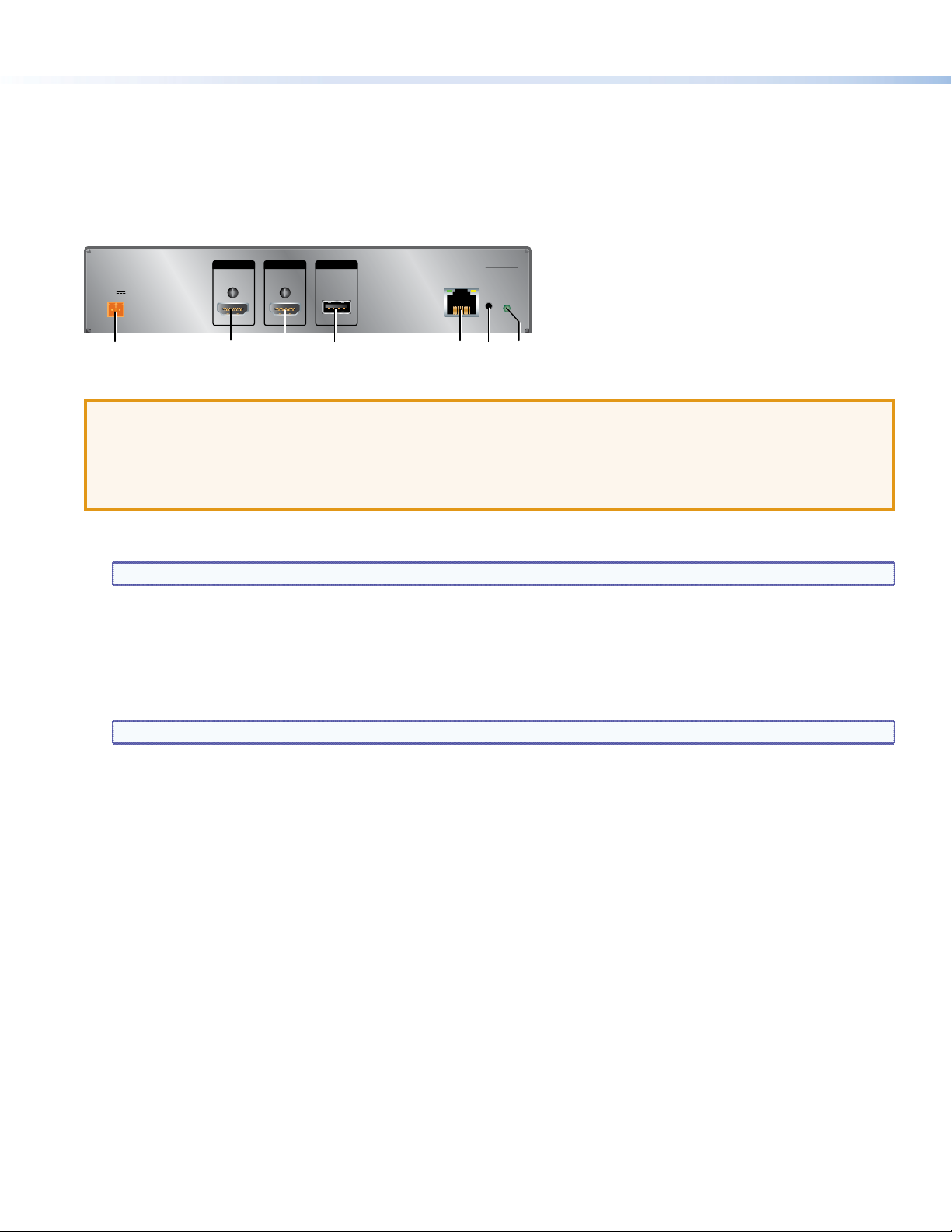
Rear Panel Connectors and Features
For complete information about the TLI Pro 101 rear-panel connectors and features, see the TLI Pro 101 User Guide.
INPUT
POWER
12 V
1.0A MAX
+
-
Figure 1. TLI Pro 101 Rear Panel
HDMIHDMI
CONTROLOUTPUT
USB
TLI PRO 101
LAN/PoE
RESET
ATTENTION: The TLP Pro 720C can use a 12 VDC desktop power supply and is also Power over Ethernet (PoE 802.3af,
class3) compliant. Do not connect either power supply before reading the Attention in the Power Supply section of the
TLPPro720C User Guide.
ATTENTION: Le TLP Pro 720C peut utiliser une source d’alimentation externe 12 Vcc, et est également compatible avec
l’alimentation POE via Ethernet (PoE 802.3af, classe 3). Ne branchez pas de sources d’alimentation externes avant d’avoir
lu les mises en garde dans la section «PowerSupply» du TLPPro720C User Guide.
Power connector — Connect the 2-pole, 3.5 mm captive screw connector from the provided 12 VDC, 1.0 A power supply to
A
this socket.
NOTE: The TLI Pro 101 also complies with Power over Ethernet standards (PoE 802.3af, class 3).
HDMI input — Plug the cable from the input source device into this female HDMI type A connector. Use the provided LockIt
B
brackets to secure the connector to the TLI Pro 101 unit.
HDMI output — Connect this female HDMI type A connector to a third-party touch screen. Use the provided LockIt brackets
C
to secure the connector to the TLI Pro 101 unit. A full list of compatible resolutions is provided in the TLI Pro 101 User Guide.
USB connector — supports High-speed USB 2.0 control. Plug a USB cable from the third-party touchpanel into this female
D
typeB connector.
NOTE: To use a monitor that is not a touchpanel, connect a mouse to this port.
Network and Power over Ethernet connector — Connect the interface to the LAN using a twisted pair cable, terminated
E
with an RJ-45 connector. The connector can also be used with a PoE power injector (not provided).
An Extron IP Link Pro control processor must also be connected to the same network as the TouchLink Pro touchpanel.
Reset button (recessed) — allows the unit to be reset in any of three different modes. For more information about Reset
F
modes see the TLI Pro 101 User Guide.
Reset mode LED — indicates power status and reset status of the device.
G
2
Page 3

Front Panel Features
ABED
C
MENU
Figure 2. TLI Pro 101 Front Panel
Power LED — Lights green when the unit is powered on.
A
Menu button (recessed) — opens the setup menu and calibration screen for the interface:
B
z Press the button briey (less than 2 seconds) to open the internal menu screens.
z Press and hold the button (at least 2 seconds) to open the calibration screen. Follow the on-screen instructions to
calibrate the touchpanel.
z Press the button briey (less than 2 seconds) for a second time to close the current screen without saving any changes.
100 Mb network LED — Lights green when the unit is connected to a 100 Mb network.
C
Network link LED — Lights green when the unit is connected to any network.
D
Network activity LED — Blinks amber when there is activity on the network connection.
E
Setup Menu
The setup menu opens when the menu button is pressed (see Front
Panel Features, B above). There are six different screens: Status,
(shown in gure3) Network, Output, Audio, Input, and Advanced.
The screens can be selected by pressing the appropriate button in the
navigation bar at the top of the screen.
Press the menu button for at least 2 seconds to open the calibration
screen. Follow the on-screen instructions.
TLI PRO 101
TOUCHLINK INTERFACE
100
LINK
ACT
Status
Network
Info
Model: TLI Pro 101
Part Number: 60-1083-01
Firmware
Version:
1.00
PoE Status:On
Output
Network
IP Address:
192.168.254.251
DHCP:
Off
Host Name:
TLI-AB-CD-EF
Audio
Master Volume:
Master Mute: Off
Advanced
Controller IP: N/A
Project Size: N/A
Audio
99
Advanced
Input
Resolution:
Project:
Sleep Timer:
Input
HDMI Port: No Signal
Output
800x600
N/A
5 Minutes
Exit
Extron Headquarters
+1.800.633.9876 (Inside USA/Canada Only)
Extron USA - West Extron USA - East
+1.714.491.1500 +1.919.850.1000
+1.714.491.1517 FAX +1.919.850.1001 FAX
© 2014 Extron Electronics All rights reserved. All trademarks mentioned are the property of their respective owners. www.extron.com
3
Extron Europe
+800.3987.6673
(Inside Europe Only)
+31.33.453.4040
+31.33.453.4050 FAX
Extron Asia
+65.6383.4400
+65.6383.4664 FAX
Extron Japan
+81.3.3511.7655
+81.3.3511.7656 FAX
Figure 3. Setup Menu
Extron China
+86.21.3760.1568
+86.21.3760.1566 FAX
Extron Middle East
+971.4.299.1800
+971.4.299.1880 FAX
Extron Korea
+82.2.3444.1571
+82.2.3444.1575 FAX
Extron India
1800.3070.3777
(Inside India Only)
+91.80.3055.3777
+91.80.3055.3737 FAX
68-1817-50 A
04 14
 Loading...