

Page 1
TeamWork® • Installation Guide
VGA
TeamWork
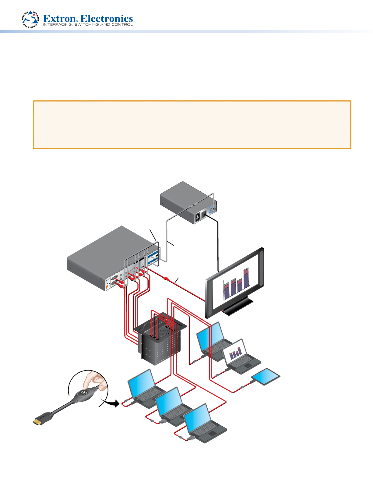
Extron TeamWork is a fully customizable collaboration system comprised of an Extron switcher, “Show Me” cables, a control
processor, and a Cable Cubby® enclosure. This installation guide provides the information needed for an experienced installer to
set up these systems.
ATTENTION:
• The information in this guide refers to a typical TeamWork system. The devices provided in your kit may differ from those
shown in the illustrations.
• If your system uses a different IPLcontroller, switcher, or Cable Cubby from the ones shown in this guide consult the user
guide for your model before connecting or conguring that device. The user guides are available on line at
www.extron.com.
In a typical TeamWork application, shown below, digital or analog input devices (laptops and a tablet) connect to the switcher,
using “Show Me” cables. The “Show Me” cables allow the user to select the input on the switcher.
US
®
7TT
1
EO
TED
ID
V
LIS
DIO/
AU
RATUS
PA
A
COM
LAN
+5VRX
TX
IR
T
INPU
IN S G
100-120V 50/60Hz
Contact Closure
& Tally
Extron
IPL T PC1
System Controller
12A MAX POWER OUTPUT 12A MAX
Flat Panel
AC Cord
1
MPS 601
RGBHV
2
POWER
AX
12V
0.5A M
Extron
MPS 601
Switcher
Extron
Cable Cubby 800
Cable Access Enclosure
SHARE
Extron
Extron “Show Me” Cables
RS-232
Control Cable
+V
C G
REMOTE
G T
RS-232
G
C T TC
1 3 5
OUTPUT
TxRx G
CONTACT IN / TALLY OUT
HDMI
2 4 6
INPUTS
C G TC G
T T
GC
5
HDMI
6
3
A
HDMI
4
B
Extron
HDMI Pro Cable
HDMI Video
X
5A MA
240V/
010
1
00-240
X
MA
V
/
5A
5A
/
M
A
X
00-240V
1
SOUTH
Regional Sales
EAST
NORTH
150
WEST
120
90
60
30
0
Flat Panel
Display w/ Integrated
Speakers
les
SOUTH
Regional Sa
NORTH
EAST
150
WEST
120
90
60
30
0
HDMI
HDMI
HDMI
HDMI
VGA
1
Page 2
TeamWork • Installation Guide (Continued)
Top of Cable Cubby
(to switcher)
Cable Cubby
closure and tally
Top of Cable Cubby
(to switcher)
y
closure and tally
INPUT
Top of Cable Cubby
Cable Cubby
closure and tally
INPUT
y
closure and tally
Mounting and Installation
Assembling the Cable Cubby
1. Install the power modules in the Cable Cubby. The power modules that you use depend on the country you are in and the
Cable Cubby model that you are using. For complete installation instructions for your Cable Cubby, see the installation guide
for that Cable Cubby, which is available at www.extron.com.
WARNING: Possible electric shock: To ensure good electric grounding, you must secure the power modules to the
Cable Cubby using screws with star washers.
2. Assemble the AAP shelf assembly and “Show Me” cables.
The AAP shelf assembly components will depend on the Cable Cubby you are using. Follow the instructions in the
CableCubby installation guide.
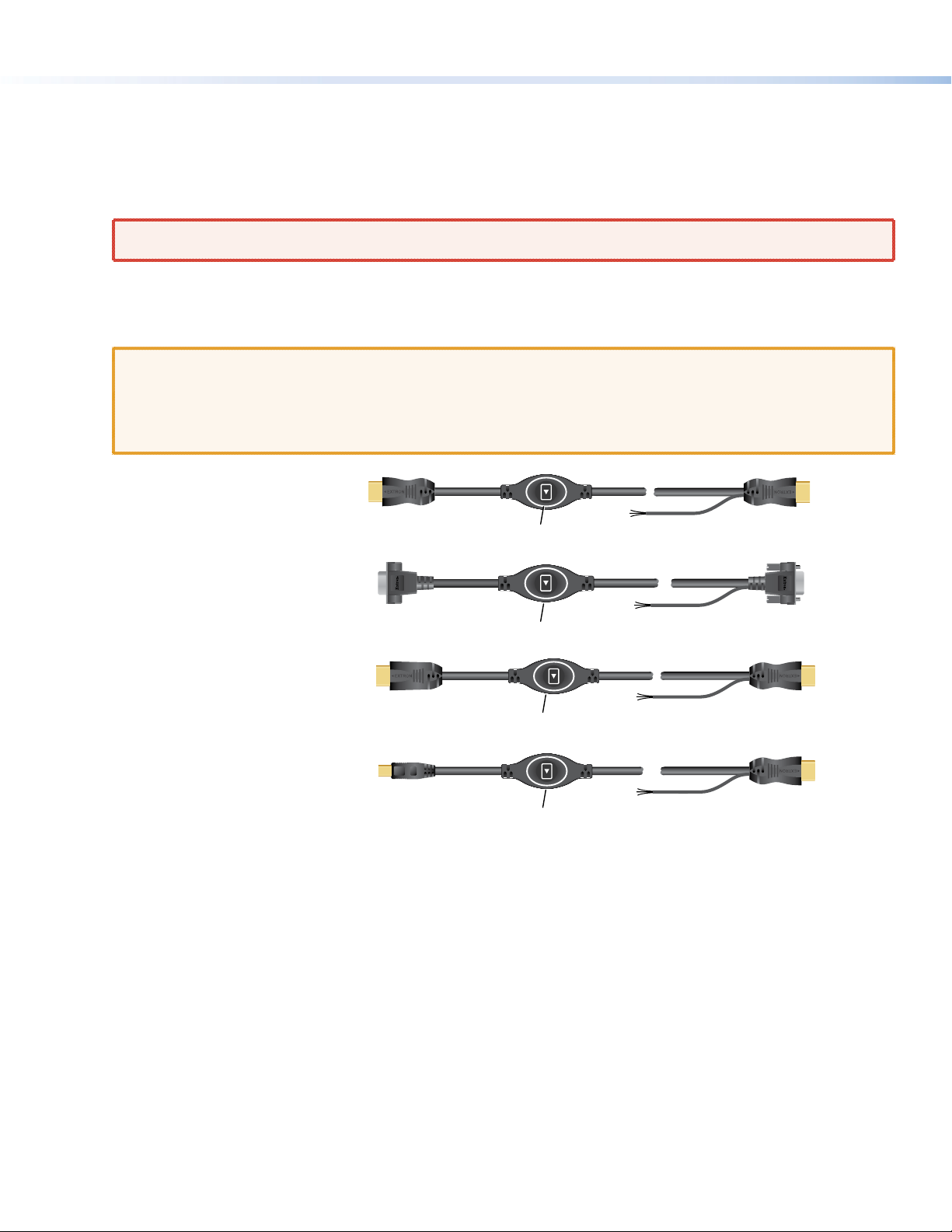
ATTENTION: The “Show Me” cables must be integrated into the AAP shelf assembly as it is being put together. Ensure
that they are installed in the correct orientation:
• The end with the button and LED connects to the input devices and must come out of the top of the Cable Cubby.
• The end with the three-conductor pigtail connects to the switcher and must come out of the bottom of the Cable
Cubby.
HDMI “Show Me” cable
VGA “Show Me” cable
Display Port
“Show Me” cable
Mini Display Port
“Show Me” cable
INPUT
(to source device)
INPUT
(to source device)
(to source device)
(to source device)
Top of Cable Cubby
Share Button
SHARE
Share Button
SHARE
Share Button
SHARE
Share Button
Three-conductor
pigtail for contact
Three-conductor
pigtail for contact
Three-conductor
pigtail for contact
Three-conductor
pigtail for contact
3. Insert the AAP assemblies into the Cable Cubby from underneath and secure them in position with the provided #4-40
Phillips head screws and star washers.
OUTPUT
Bottom of
OUTPUT
Bottom of
Cable Cubb
OUTPUT
(to switcher)
Bottom of
OUTPUT
(to switcher)
Bottom of
Cable Cubb
2
Page 3
Mounting and Placement of System Components
Decide where you will install your TeamWork system and where the individual components will be placed.
z The Cable Cubby should provide easy access for as many users as possible. Ensure that there is ample space for cables
under the table. Ensure that the edge on which the lid opens is correctly oriented.
z The system controller should be placed close to the display.
z The switcher should be placed close to the Cable Cubby.
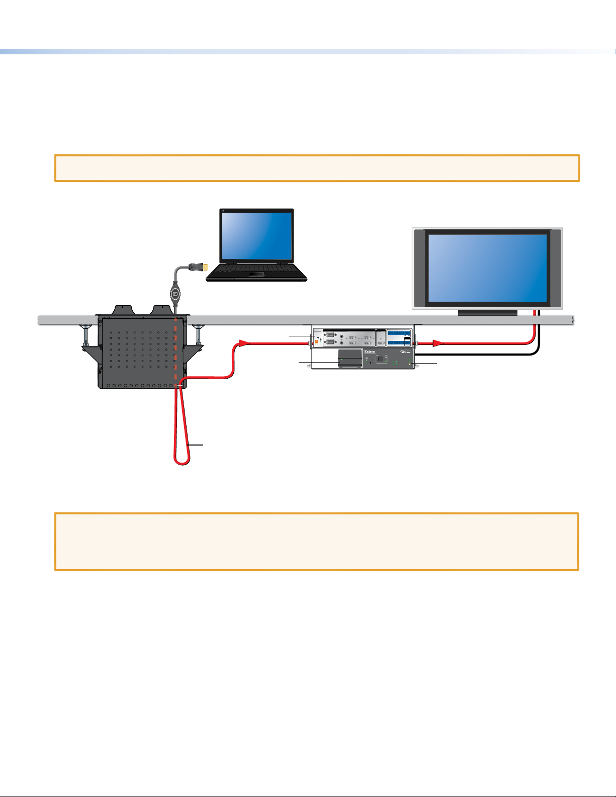
ATTENTION: The illustration below shows the devices mounted with the optional Extron UTS 100 and UTS 150 under-table
shelf system. This is not a mounting option for all TeamWork kits, as some components are too wide to t in the shelves.
1080p Native
Resolution Display
HDMI ”Show Me”
Cable
Extron
Cable Cubby
Cable Access Enclosure
Switcher
Power
Supply
Secure “Show Me” Cable
to Cable Cubby and create a
loop.
MPS 601
POWER
12V
0.5 A MAX
Shown mounted with
optional Extron UTS 100/UTS 150
Under Table Shelf System.
INPUTS
1
A
RGBHV
2
B
345
HDMI
OUTPUT
HDMI
GCT TCG T+VCG
135
CONTACT IN / TALLY OUT
REMOTE
HDMI
6
IPL T PC1
R
RS-232
246
GC
TTCG TCG
TxRx G
POWER
100
TXRXINPUT
LINK
IR
ACT
HDMI Video to Display
AC Power To Display
System Controller
Installing the Cable Cubby in the Table
Before cutting the table and installing the Cable Cubby, see the Cable Cubby Setup Guide (see www.extron.com).
ATTENTION:
• Use the provided cut-out template and ensure that the orientation of the Cable Cubby and the hole dimensions are
correct before cutting the table.
• After installation, secure the cables to avoid them becoming tangled (see the gure above).
3
Page 4
TeamWork • Installation Guide (Continued)
VGA
Cabling
100-120V 50/60Hz
12A MAX POWER OUTPUT 12A MAX
13
Extron
MPS 601
Switcher
5
+V
REMOTE
RS-232
TxRx G
Extron
HDMI Pro Cable
HDMI Video
X
5A MA
240V/
010
X
MA
V
/
5A
5A
/
M
A
X
00-240V
1
Extron
IPL T PC1
System Controller
RS-232
Control Cable
1
00-240
Contact Closure
& Tally
C G
G T
G
C T TC
1 3 5
OUTPUT
CONTACT IN / TALLY OUT
HDMI
2 4 6
INPUTS
C G TC G
T T
GC
5
HDMI
6
3
A
HDMI
4
1
MPS 601
RGBHV
B
2
POWER
AX
12V
0.5A M
2
6
US
®
7TT
1
EO
TED
ID
V
LIS
DIO/
AU
RATUS
PA
A
COM
LAN
+5VRX
TX
IR
T
INPU
IN S G
6
Flat Panel
AC Cord
4
SOUTH
Regional Sales
EAST
NORTH
150
WEST
120
90
60
30
0
Flat Panel
Display w/ Integrated
Speakers
Extron
Cable Cubby 800
Cable Access Enclosure
SHARE
Extron
Extron “Show Me” Cables
HDMI
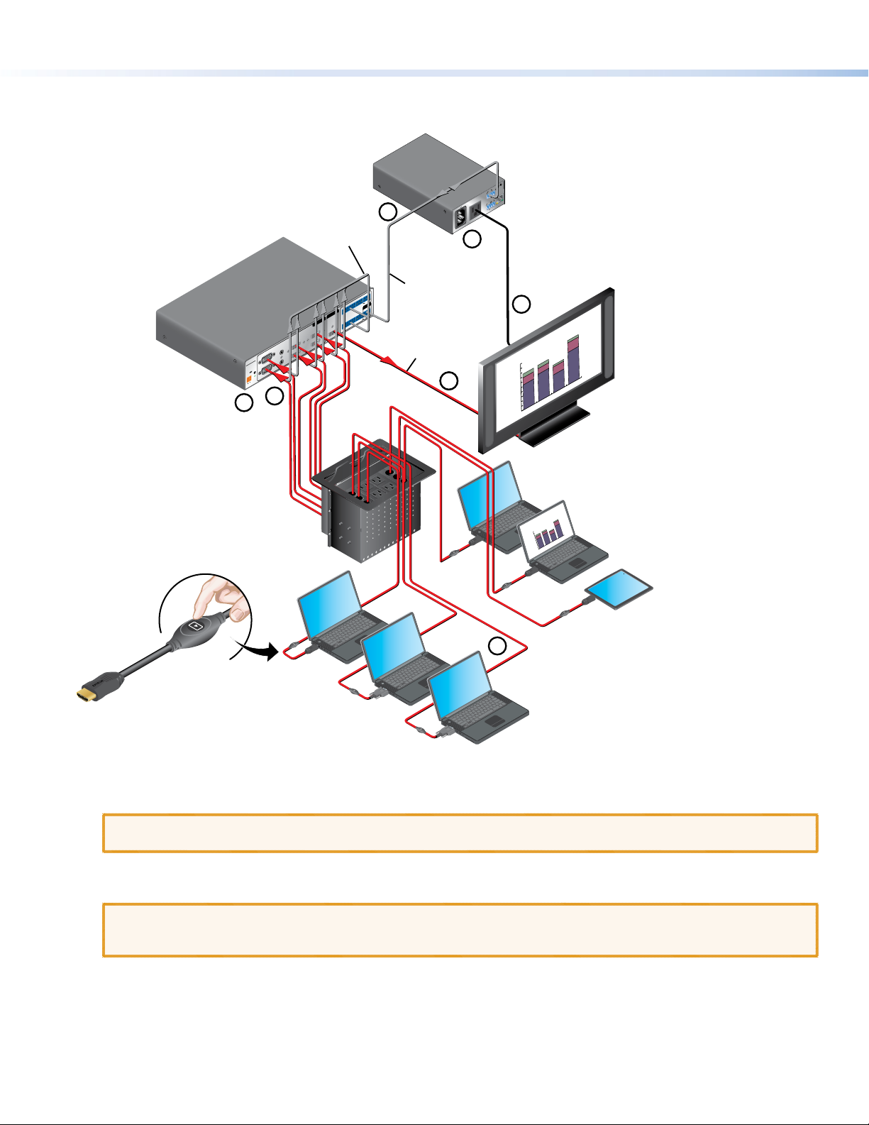
a Connect the “Show Me” cables to the source devices.
b Connect the “Show Me” cables to the switcher.
ATTENTION: If you have analog and digital video inputs, ensure that your TeamWork switcher can accept both types of
signal. If not, you need the VGA TeamWork kit to convert the analog signal.
c Connect the switcher to the display.
d Connect the display to the system controller.
ATTENTION: The illustration above shows the IPL T PC1, which controls AC power to the display. The controller in your
TeamWork kit may control the display by IR or RS-232 and connections between the controller and the display will
differ from those shown above.
VGA
HDMI
1
HDMI
les
SOUTH
Regional Sa
NORTH
EAST
150
WEST
120
90
60
30
0
HDMI
e Connect the system controller to the switcher.
f Connect power to the switcher and system controller.
4
Page 5

“Show Me” Cables
Top of Cable Cubby
(to switcher)
Cable Cubby
closure and tally
“Show Me” Cable
Switcher End
(Output)
Extron MPS 601 Switcher
The Extron “Show Me” cables are for use with Extron TeamWork systems. They feature a Share button for remote input source
selection and a control pigtail, which may be wired directly into Extron switchers with contact closure and tally outputs. The gure
below shows the HDMI “Show Me” cable, but all the “Show Me” cables have these same features (see the gure on page 2)
INPUT
(to source device)
Share Button
Three-conductor
pigtail for contact
Connecting “Show Me” Cables
1. Connect the input end of the “Show Me” cable to the source device.
2. Connect the video output to the Extron switcher.
OUTPUT
Bottom of
MPS 601
1
POWER
12V
0.5 A MAX
2
Male VGA Connector
RGBHV
INPUTS
A
3
HDMI
4
B
Male HDMI Connector
5
6
OUTPUT
HDMI
Three-conductor
pigtail for contact
closure and tally
HDMI
GCT TCG T+VCG
135
CONTACT IN / TALLY OUT
246
GC
TTCG TCG
REMOTE
RS-232
Tx Rx G
Red
(C)
3. Connect the black (Tally Out), red (Contact In), and drain wire (ground) pigtail wires.
ATTENTION:
• The gure above illustrates how “Show Me” cables connect to the Extron MPS 601 switcher. The contact, tally out,
and ground connectors may be organized differently on your switcher. Ensure the port number for the contact, tally
out, and ground wires matches the video input port number. In the example above, the VGA connector is inserted into
Video Input 2 and the pigtail connectors are also connected to port 2.
• The video input must be grounded. For some switchers, the “Show Me” cables are grounded via the video
connectors. If this is not the case, it is necessary to connect the drain wire to the ground (G) connector.
• Do not connect the “Show Me” cable to the +V pin on the Extron switcher.
GCT TCG TCG
135
CONTACT IN / TALLY OUT
246
GC
TTCG TCG
Drain wire (G)
Black
(T)
Pigtail
Connect the Switcher to the Display Device
Connect the switcher HDMI output to the HDMI input of the display device, using the provided cable. Do not use HDMI to DVI
adapters. If necessary, see the user guide for the display device.
Press the Share button to switch the connected source to the main presentation display.
Pressing the Share button creates a momentary contact closure, which triggers the switcher to select the connected source
device. If a tally output is available, the button will light up blue.
NOTES:
• The source device provides the +5 VDC supply voltage needed to illuminate the Share button. If the source device
does not supply this +5VDC, the Share button will not illuminate. Some mobile devices do not provide the required
voltage to light up the button.
• Digital “Show Me” cables support embedded audio and CEC signals.
5
Page 6

TeamWork • Installation Guide (Continued)
COM
4-pole connector
(to system contr
System Cont
(IPL T PC1)
Switcher
3-pole connector
Switcher Control Cable
System Controller
The display and switcher in your system may be controlled by RS-232, Ethernet, or IR, depending on the models. The IPLink
control processor must be congured to communicate correctly with the display and switcher. See the user guide for the
controller for complete instructions about conguration. The guide is available at www.extron.com.
Connect the Display to the System Controller
Before connecting the controller to the display, see the user guide for that device. The guide is available at www.extron.com.
ATTENTION: If you are using the IPL T PC1i (International TeamWork kits) you must replace the power plug on the display
with the provided adapter (see IEC C14 Male Power Cord Plug Installation on page 8).
Connect the System Controller to the Switcher
To connect the system controller to the switcher, you may need to make your own control cable.
The required captive screw connector is provided with each unit. The exact size (3-pole, 4-pole, or 5-pole) depends on the unit.
Although the number of wires that the connector can take varies, only three poles are required in each case: Tx, Rx, and ground.
In the gure below, the 4-pole COM port of the IPL T PC1 controller connects to the 3-pole RS-232 port of the MPS 601 switcher.
(MPS 601)
REMOTE
RS-232
Tx Rx G
3/16" (5 mm)
Max.
oller)
TX +5VRX
roller
COM
TX +5VRX
4-pole connector
(to system controller)
To make a control cable:
1. Strip the outer sheath from each end of the control cable to expose about 1 inch of the three wires.
2. Strip 3/16 inch of the sheath from each individual wire.
3. On the captive screw connector provided with the controller, identify which pins correspond to Tx, Rx, and ground on the
controller COM port.
4. Connect the three wires from one end of the control cable to the Tx, Rx, and ground pins of the captive screw connector.
5. On the captive screw connector provided with the switcher, identify which pins correspond to Tx, Rx, and ground on the
RS-232 port of the switcher.
6. Connect the three wires from the other end of the control cable as follows:
z Controller Tx connects to switcher Rx
z Controller Rx connects to switcher Tx
z Controller ground connects to switcher ground
7. Secure the control cable to the captive screw connectors at both ends using the cable tie provided.
(to switcher)
Connect Power
6
If the device has an internal power supply, connect the power cord to a wall outlet.
If the device requires a power supply, connect the power supply provided to the device.
ATTENTION: Do not connect any external power supplies until you have read the Attention notications in the “Power
Supply” section of the user guide for that device.
Page 7

Addendum
Ext
V
Resolution Display
.
This section provides additional information about the specic requirements of the IPL T PC1 and IPL T PC1i controllers.
TeamWork systems require a display that
When using the IPL T PC1i system controller
(International TeamWork kits) you must replace
the power plug on the display with the
provided
IEC C14 male power cord plug
(see page 8).
Extron
100-120VAC 50/60Hz
IPL T PC1 or
IPL T PC1i
12A MAX
ron
GA and HDMI Switcher
MPS 601
1
POWER
12V
0.5 A MAX
2
INPUTS
A
RGBHV
3
HDMI
4
B
OUTPUT
5
HDMI
HDMI
6
POWER OUTPUT 12A MAX
GCT TCG T+VCG
135
CONTACT IN / TALLY OUT
246
GC
TTCG TCG
Teamwork Systems work
by controlling AC power
to the display.
®
US
LISTED 17TT
COM
AUDIO/VIDEO
APARATUS
Tx
Rx +5V
LAN
INPUT IR
IN SG
RS-232
Switcher Control
REMOTE
RS-232
Tx Rx G
AC Power
returns to the previous state when the power
cord is disconnected and then plugged back
in.
How to check if a display is compatible:
1. Apply AC power to the display.
2. Turn the display on.
3. Select the video input.
4. Adjust the volume.
5. Unplug the display (remove AC power).
6. Re-apply AC power to the display.
If the display powers back up (to the on state)
and to the same input and volume level, the
display will work with the TeamWork system.
For audio playback,
display should have
integrated speakers
Display should have an HDMI
input and support embedded
audio.
Display Requirements for the IPL T PC1 and IPL T PC1i
1080p Native
ATTENTION: This section applies to the IPL T PC1 and the IPL T PC1i, which controls the AC power to the display. If a
different controller is used, it needs to be congured differently (see the user guide for the controller at www.extron.com).
The TeamWork system works with most brands and models of at panel displays available worldwide. For optimum performance,
consider the following when selecting the displays for your TeamWork installation. The display should be tested thoroughly prior
to installation or mass deployment of TeamWork systems.
Power attributes — The IPL T PC1 works by controlling AC power to the display. When the display is in the on state with
an HDMI input selected, it must be able to power back on to the same HDMI input when AC power is disconnected and
reconnected. If the display doesn’t behave this way, an alternate display should be used. Alternatively, you may need to control
the display a different way (for example RS-232, infrared, or via Ethernet) using a different type of Extron control processor.
Sleep mode — if the display has a sleep mode feature (sometimes called ‘auto sleep’), it must be disabled. Many displays have
an option to disable this within the menu settings.
Resolution — The TeamWork systems were designed for use with at panels having an HDMI input connector and having a
native resolution of 1080p. Many of the readily available consumer and professional displays support 1080p natively.
Audio — Audio from source devices is supported in the TeamWork system by routing it as an embedded audio signal to the
display for playback via integrated speakers. Most displays with HDMI inputs and integrated speakers work this way. Some
professional or commercial grade displays do not have integrated speakers and will not support audio playback. Typically, source
devices with HDMI output connectors embed audio onto the HDMI connector.
7
Page 8

TeamWork • Installation Guide (Continued)
NOTES:
• Always check and test compatibility before installation. Some systems may require advanced conguration of the system
controller and require the display to be controlled by RS-232, Ethernet, or infrared.
• Some displays support a lockout of local buttons. Extron recommends that, after setup, user accessible controls are
locked whenever possible. This ensures the display remains optimized for the TeamWork system.
IEC C14 Male Power Cord Plug Installation
When using the IPL T PC1i system controller (International TeamWork kits) you must replace the power plug on the display with
the provided IEC C14 male power cord plug. This plug has a maximum current rating of 10 A and a maximum voltage of 250 VAC.
WARNING: High Voltage. Failure to follow these instructions may result in serious injury.
• Installation and service of the power cord plug must be performed by authorized personnel only.
• Observe the correct wire polarity.
• Before installation, disconnect the display from the power source or any other device.
NOTE: The power cord plug shown in the gure is for illustration only. The plug provided may not look exactly the same.
1. Cut the existing plug from the
LGN
power cord.
4. Loosen the screw and remove the top
plate.
2. Remove a suitable amount of
the outer sheath from the
power cord.
Individual wires should not
extend from the back of the
strain relief after the plug is
installed.
3. Strip a suitable amount of the
5. If required, loosen the white plastic wire
clamp.
jacket from the three wires.
There should be just enough
bare metal to wrap around
the screw in step 7.
Ground
(Earth)
Live
(Hot)
Neutral
6. Thread the cord through the strain relief.
7. Use a at head screwdriver to secure the
individual wires to the correct connector.
WARNING: Observe the correct wire
polarity (see the diagram to the left).
8. Secure the wires by tightening the white
plastic wire clamp.
9. Reattach the top plate and screw that were
removed in step 4.
Extron Headquarters
+1.800.633.9876 (Inside USA/Canada Only)
Extron USA - West Extron USA - East
+1.714.491.1500 +1.919.850.1000
+1.714.491.1517 FAX +1.919.850.1001 FAX
8
Extron Europe
+800.3987.6673
(Inside Europe Only)
+31.33.453.4040
+31.33.453.4050 FAX
© 2014 Extron Electronics All rights reserved. www.extron.com
Extron Asia
+65.6383.4400
+65.6383.4664 FAX
Extron Japan
+81.3.3511.7655
+81.3.3511.7656 FAX
Extron China
+86.21.3760.1568
+86.21.3760.1566 FAX
Extron Middle East
+971.4.299.1800
+971.4.299.1880 FAX
Extron Korea
+82.2.3444.1571
+82.2.3444.1575 FAX
Extron India
1800.3070.3777
(Inside India Only)
+91.80.3055.3777
+91.80.3055.3737 FAX
68-2615-50 Rev. A
02 14
 Loading...