

Page 1

SW4 12G HD-SDI
HD-SDI Switcher
User Guide
HD-SDI Switchers
68-3187-01 Rev. A
02 19
Page 2

Safety Instructions
Safety Instructions • English
WARNING: This symbol, , when used on the product, is intended to
alert the user of the presence of uninsulated dangerous voltage within the
product’s enclosure that may present a risk of electric shock.
ATTENTION: This symbol, , when used on the product, is intended
to alert the user of important operating and maintenance (servicing)
instructions in the literature provided with the equipment.
For information on safety guidelines, regulatory compliances, EMI/EMF
compatibility, accessibility, and related topics, see the Extron Safety and
Regulatory Compliance Guide, part number 68-290-01, on the Extron
website, www.extron.com.
Sicherheitsanweisungen • Deutsch
WARNUNG: Dieses Symbol auf dem Produkt soll den Benutzer darauf
aufmerksam machen, dass im Inneren des Gehäuses dieses Produktes
gefährliche Spannungen herrschen, die nicht isoliert sind und die einen
elektrischen Schlag verursachen können.
VORSICHT: Dieses Symbol auf dem Produkt soll dem Benutzer in
der im Lieferumfang enthaltenen Dokumentation besonders wichtige
Hinweise zur Bedienung und Wartung (Instandhaltung) geben.
Weitere Informationen über die Sicherheitsrichtlinien, Produkthandhabung,
EMI/EMF-Kompatibilität, Zugänglichkeit und verwandte Themen finden Sie in
den Extron-Richtlinien für Sicherheit und Handhabung (Artikelnummer
68-290-01) auf der Extron-Website, www.extron.com.
Instrucciones de seguridad • Español
ADVERTENCIA: Este símbolo, , cuando se utiliza en el producto,
avisa al usuario de la presencia de voltaje peligroso sin aislar dentro del
producto, lo que puede representar un riesgo de descarga eléctrica.
ATENCIÓN: Este símbolo, , cuando se utiliza en el producto, avisa
al usuario de la presencia de importantes instrucciones de uso y
mantenimiento recogidas en la documentación proporcionada con el
equipo.
Para obtener información sobre directrices de seguridad, cumplimiento
de normativas, compatibilidad electromagnética, accesibilidad y temas
relacionados, consulte la Guía de cumplimiento de normativas y seguridad
de Extron, referencia 68-290-01, en el sitio Web de Extron, www.extron.com.
Instructions de sécurité • Français
AVERTISSEMENT : Ce pictogramme, , lorsqu’il est utilisé sur le
produit, signale à l’utilisateur la présence à l’intérieur du boîtier du
produit d’une tension électrique dangereuse susceptible de provoquer
un choc électrique.
Istruzioni di sicurezza • Italiano
AVVERTENZA: Il simbolo, , se usato sul prodotto, serve ad
avvertire l’utente della presenza di tensione non isolata pericolosa
all’interno del contenitore del prodotto che può costituire un rischio di
scosse elettriche.
ATTENTZIONE: Il simbolo, , se usato sul prodotto, serve ad avvertire
l’utente della presenza di importanti istruzioni di funzionamento e
manutenzione nella documentazione fornita con l’apparecchio.
Per informazioni su parametri di sicurezza, conformità alle normative,
compatibilità EMI/EMF, accessibilità e argomenti simili, fare riferimento
alla Guida alla conformità normativa e di sicurezza di Extron, cod. articolo
68-290-01, sul sito web di Extron, www.extron.com.
Instrukcje bezpieczeństwa • Polska
OSTRZEŻENIE: Ten symbol, , gdy używany na produkt, ma na celu
poinformować użytkownika o obecności izolowanego i niebezpiecznego
napięcia wewnątrz obudowy produktu, który może stanowić zagrożenie
porażenia prądem elektrycznym.
UWAGI: Ten symbol, , gdy używany na produkt, jest przeznaczony do
ostrzegania użytkownika ważne operacyjne oraz instrukcje konserwacji
(obsługi) w literaturze, wyposażone w sprzęt.
Informacji na temat wytycznych w sprawie bezpieczeństwa, regulacji
wzajemnej zgodności, zgodność EMI/EMF, dostępności i Tematy pokrewne,
zobacz Extron bezpieczeństwa i regulacyjnego zgodności przewodnik, część
numer 68-290-01, na stronie internetowej Extron, www.extron.com.
Инструкция по технике безопасности • Русский
ПРЕДУПРЕЖДЕНИЕ: Данныйсимвол, ,еслиуказан
напродукте,предупреждаетпользователяоналичии
неизолированногоопасногонапряжениявнутрикорпусапродукта,
котороеможетпривестикпоражениюэлектрическимтоком.
ВНИМАНИЕ: Данныйсимвол, ,еслиуказаннапродукте,
предупреждаетпользователяоналичииважныхинструкцийпо
эксплуатациииобслуживаниювруководстве,прилагаемомк
данномуоборудованию.
Дляполученияинформацииоправилахтехникибезопасности,
соблюдениинормативныхтребований,электромагнитнойсовместимости
(ЭМП/ЭДС),возможностидоступаидругихвопросахсм.руководствопо
безопасностиисоблюдениюнормативныхтребованийExtronнасайте
Extron:,www.extron.com, номерпокаталогу - 68-290-01.
安全说明 • 简体中文
警告: 产品上的这个标志意在警告用户该产品机壳内有暴露的危险 电压,
有触电危险。
ATTENTION : Ce pictogramme, , lorsqu’il est utilisé sur le produit,
signale à l’utilisateur des instructions d’utilisation ou de maintenance
importantes qui se trouvent dans la documentation fournie avec le
matériel.
Pour en savoir plus sur les règles de sécurité, la conformité à la
réglementation, la compatibilité EMI/EMF, l’accessibilité, et autres sujets
connexes, lisez les informations de sécurité et de conformité Extron, réf.
68-290-01, sur le site Extron, www.extron.com.
注意: 产品上的这个标志意在提示用户设备随附的用户手册中有
重要的操作和维护(维修)说明。
关于我们产品的安全指南、遵循的规范、EMI/EMF 的兼容性、无障碍
使用的特性等相关内容,敬请访问 Extron 网站 , www.extron.com,参见
Extron 安全规范指南,产品编号 68-290-01。
Page 3

安全記事 • 繁體中文
警告: 若產品上使用此符 號,是為了提醒使用者,產品機殼內存在著
可能會導致觸電之風險的未絕緣危險電壓。
注意 若產品上使用此符號,是為了提醒使用者,設備隨附的用戶手冊中有
重要的操作和維護(維修)説明。
有關安全性指導方針、法規遵守、EMI/EMF 相容性、存取範圍和相關主題的詳細資
訊,請瀏覽 Extron 網站:www.extron.com,然後參閱《Extron 安全性與法規
遵守手冊》,準則編號 68-290-01。
安全上のご注意 • 日本語
警告: この記 号 が製品上に表示されている場合は、筐体内に絶縁されて
いない高電圧が流れ、感電の危険があることを示しています。
注意:この記号 が製品上に表示されている場合は、本機の取扱説明書に
記載されている重要な操作と保守( 整備)の 指示についてユーザーの注 意
を喚起するものです。
安全上のご注意、法規厳守、EMI/EMF適合性、その他の関連項目に
つ い て は 、エ ク ストロ ン の ウ ェブ サ イト www.extron.com よ り 『 Extron Safety
and Regulatory Compliance Guide』 ( P/N 68-290-01) をご覧ください。
안전 지침 • 한국어
경고: 이기호 가제품에사용될경우,제품의인클로저내에있는
접지되지않은위험한전류로인해사용자가감전될위험이있음을
경고합니다.
주의: 이기호 가제품에사용될경우,장비와함께제공된책자에나와
있는주요운영및유지보수(정비)지침을경고합니다.
안전가이드라인,규제준수,EMI/EMF호환성,접근성,그리고관련항목에
대한자세한내용은Extron웹사이트(www.extron.com)의Extron안전및
규제준수안내서,68-290-01조항을참조하십시오.
Copyright
© 2019 Extron Electronics. All rights reserved. www.extron.com
Trademarks
All trademarks mentioned in this guide are the properties of their respective owners.
The following registered trademarks (®), registered service marks (SM), and trademarks (TM) are the property of RGBSystems, Inc. or
ExtronElectronics (see the current list of trademarks on the Terms of Use page at www.extron.com):
Registered Trademarks (
®
)
Extron, Cable Cubby, ControlScript, CrossPoint, DTP, eBUS, EDID Manager, EDID Minder, Flat Field, FlexOS, Glitch Free. Global
Configurator, GlobalScripter, GlobalViewer, Hideaway, HyperLane, IPIntercom, IPLink, KeyMinder, LinkLicense, LockIt, MediaLink,
MediaPort, NetPA, PlenumVault, PoleVault, PowerCage, PURE3, Quantum, Show Me, SoundField, SpeedMount, SpeedSwitch,
StudioStation, SystemINTEGRATOR, TeamWork, TouchLink, V-Lock, VideoLounge, VN-Matrix, VoiceLift, WallVault, WindoWall, XTP,
XTPSystems, and ZipClip
Registered Service Mark
(SM)
: S3 Service Support Solutions
Trademarks (™
)
AAP, AFL (Accu-RateFrameLock), ADSP(Advanced Digital Sync Processing), Auto-Image, AVEdge, CableCover, CDRS(ClassD
Ripple Suppression), Codec Connect, DDSP(Digital Display Sync Processing), DMI (DynamicMotionInterpolation), DriverConfigurator,
DSPConfigurator, DSVP(Digital Sync Validation Processing), eLink, EQIP, Everlast, FastBite, FOX, FOXBOX,
IP Intercom HelpDesk, MAAP, MicroDigital, Opti-Torque, PendantConnect, ProDSP, QS-FPC(QuickSwitch Front Panel Controller),
RoomAgent, Scope-Trigger, ShareLink, SIS, SimpleInstructionSet, Skew-Free, SpeedNav, Triple-Action Switching, True4K, Vector™ 4K ,
WebShare, XTRA, and ZipCaddy
Page 4

FCC Class A Notice
This equipment has been tested and found to comply with the limits for a Class A digital
device, pursuant to part15 of the FCC rules. The ClassA limits provide reasonable
protection against harmful interference when the equipment is operated in a commercial
environment. This equipment generates, uses, and can radiate radio frequency energy and,
if not installed and used in accordance with the instruction manual, may cause harmful
interference to radio communications. Operation of this equipment in a residential area is
likely to cause interference. This interference must be corrected at the expense of the user.
NOTE: For more information on safety guidelines, regulatory compliances, EMI/EMF
compatibility, accessibility, and related topics, see the Extron Safety and Regulatory
Compliance Guide on the Extron website.
VCCI-A Notice
この装置は、クラスA情報技術装置です。 この装置を家庭環境で使用すると、電波妨害を引き
起こすことがあります。 その場合には使用者が適切な対策を講ずるよう要求されることがあります。
VCCI -A
Battery Notice
This product contains a battery. Do not open the unit to replace the battery. If the
battery needs replacing, return the entire unit to Extron (for the correct address, see the
Extron Warranty section on the last page of this guide).
CAUTION: Risk of explosion. Do not replace the battery with an incorrect type. Dispose
of used batteries according to the instructions.
ATTENTION : Risque d’explosion. Ne pas remplacer la pile par le mauvais type de pile.
Débarrassez-vous des piles usagées selon le mode d’emploi.
Page 5

Conventions Used in this Guide
Notifications
The following notifications are used in this guide:
CAUTION: Risk of minor personal injury.
ATTENTION : Risque de blessuremineure.
ATTENTION:
• Risk of property damage.
• Risque de dommages matériels.
NOTE: A note draws attention to important information.
Software Commands
Commands are written in the fonts shown here:
^AR Merge Scene,,0p1 scene 1,1 ^B 51 ^W^C.0
[01] R 0004 00300 00400 00800 00600 [02] 35 [17] [03]
E X! *X1&* X2)* X2#* X2! CE}
NOTE: For commands and examples of computer or device responses used in this
guide, the character “0” is used for the number zero and “O” is the capital letter
“o.”
Computer responses and directory paths that do not have variables are written in the font
shown here:
Reply from 208.132.180.48: bytes=32 times=2ms TTL=32
C:\Program Files\Extron
Variables are written in slanted form as shown here:
ping xxx.xxx.xxx.xxx —t
SOH R Data STX Command ETB ETX
Selectable items, such as menu names, menu options, buttons, tabs, and field names are
written in the font shown here:
From the File menu, select New.
Click the OK button.
Specifications Availability
Product specifications are available on the Extron website, www.extron.com.
Extron Glossary of Terms
A glossary of terms is available at: http://www.extron.com/technology/glossary.aspx.
Page 6

Page 7

Contents
Introduction ...............................................1
About this Guide .................................................. 1
About the SW4 12G HD-SDI Switcher ................. 1
Features .............................................................. 1
Application Diagram ............................................ 2
Installation ................................................. 3
Installation Overview ............................................ 3
Rear Panel Features ............................................ 4
Wiring for RS-232 Control ................................... 5
Operation ................................................... 6
Front Panel Features ............................................ 6
Operations........................................................... 7
Selecting an Input ............................................ 7
Auto-input Switching ....................................... 7
Resetting ......................................................... 7
Locking the Front Panel (Executive Mode)........ 8
SIS Configuration and Control ...................9
Using Simple Instruction Set (SIS) Commands ..... 9
Host-to-switcher Communications .................. 9
Switcher-initiated Messages ............................ 9
Error Responses ............................................ 10
Using the Command and Response Table ..... 10
Symbol Definitions ......................................... 11
Command and Response Table for SIS
Commands ...................................................... 12
Software Configuration and Control ........15
Downloading and Installing PCS ........................ 15
Downloading PCS from the Download
Center Page ................................................. 15
Installing Using the PCS Product Page .......... 17
Starting PCS ..................................................... 19
Using PCS ......................................................... 20
Main Window Overview ................................. 20
Menus ........................................................... 21
AV Controls ................................................... 23
General Settings ............................................ 23
Resetting the Unit .......................................... 26
Updating Firmware using PCS ....................... 27
Reference Information ............................. 31
Mounting the SW4 12G HD-SDI Switchers ........ 31
Tabletop Use ................................................. 31
Rack Mounting .............................................. 31
Furniture Mounting......................................... 32
Updating Firmware using Firmware Loader ........ 32
Downloading Firmware Loader ...................... 32
Updating Firmware Using Firmware
Loader .......................................................... 34
viiSW4 12G HD-SDI • Contents
Page 8

SW4 12G HD_SDI • Contents viii
Page 9

Introduction
This section gives an overview of the Extron SW4 12G HD-SDI switcher. Topics include:
• About this Guide
• About the SW4 12G HD-SDI Switcher
• Features
• Application Diagram
About this Guide
This guide describes the SW4 12G HD-SDI switcher and discusses how to install, configure,
and operate it.
In this guide, the terms “SW4 12G HD-SDI” and “switcher” are used interchangeably to refer
to the SW4 12G HD-SDI switcher.
About the SW4 12G HD-SDI Switcher
Features
The Extron SW4 12G HD-SDI is a four-input, two-output 12G-SDI switcher. It switches
multi-rate SDI video, embedded audio, and other ancillary data between four source devices
and delivers simultaneous output signals to a pair of SDI displays or sink devices. The
SW4 12G HD-SDI supports video resolutions up to 4K @ 60 Hz, HDR, and data rates up
to 11.88 Gbps, including all common serial digital video data rates specified by SMPTE
and ITU standards. To ensure signal integrity over long cable runs, the switcher features
automatic input cable equalization and output reclocking. The SW4 12G HD-SDI provides
RS-232, front panel, and auto-input switching control options.
• Inputs — Four female BNC connectors.
• Outputs — Two female BNC connectors.
• Automatically adapts to SMPTE and ITU digital video standards for SDI signals
up to a 12G-SDI data rate.
• Supports data rates from 270 Mbps to 11.88 Gbps.
• Supports video resolutions up to 4K @ 60 Hz — The SW4 12G HD-SDI supports
resolutions up to 4096x2160 @ 60 Hz with 4:2:2 or 4:2:0 chroma sampling at 10 bits
per color.
• Support for High Dynamic Range (HDR) video — Enables greater contrast range
and wider color gamut by providing the necessary video bandwidth, color depth, and
metadata interchange capability for HDR video.
• Dual buffered output — Allows for simultaneous viewing and recording of the selected
input signal, eliminating the cost of a separate distribution amplifier.
• Automatic input cable equalization — Compensates for attenuation on the selected
signal and automatically equalizes cables at distances up to 230 feet (70 meters) for
12G-SDI signals, 787 feet (240 meters) for HD-SDI, and 984 feet (300 meters) for SDI.
SW4 12G HD-SDI • Introduction 1
Page 10
• Automatic output reclocking — Reshapes and restores timing of digital video signals
k
at each output for recognized input data rates, eliminating high frequency jitter and
provides AV system designers with additional headroom when connecting multiple
devices.
• Passes ancillary data including HDR, embedded audio, closed captioning, and
time code — Up to 16 channels of embedded audio at 48 kHz, 24-bit audio, closed
captions, and time code are passed through to both outputs.
• Video output muting — The dual buffered output can be muted via SIS commands,
allowing the user to control when video is displayed.
• Input rate LEDs — Convenient front panel indicators allow visual confirmation
of 12G-SDI, 6G-SDI, 3G-SDI, HD-SDI, and SDI input data rates for quick, visual
identification of the selected digital video signal.
• Extron Product Configuration Software (PCS) — Provides a convenient method of
configuring multiple products using a single software application.
• Multiple control options including RS-232, front panel, and auto-input switching.
• Auto-input switching — Automatically switches to highest or lowest numbered input
with an active video signal, based on configured priority.
• Front panel security lockout — Prevents unauthorized use in non-secure
environments.
• Front panel USB configuration port — Provides convenient access for setup,
configuration, and firmware updates.
• Rack mountable, 1U half rack width metal enclosure
• Internal Extron Everlast™ power supply — Provides worldwide power compatibility,
with high demonstrated reliability and low power consumption for reduced operating
cost.
• Extron Everlast Power Supply is covered by a 7-year parts and labor warranty.
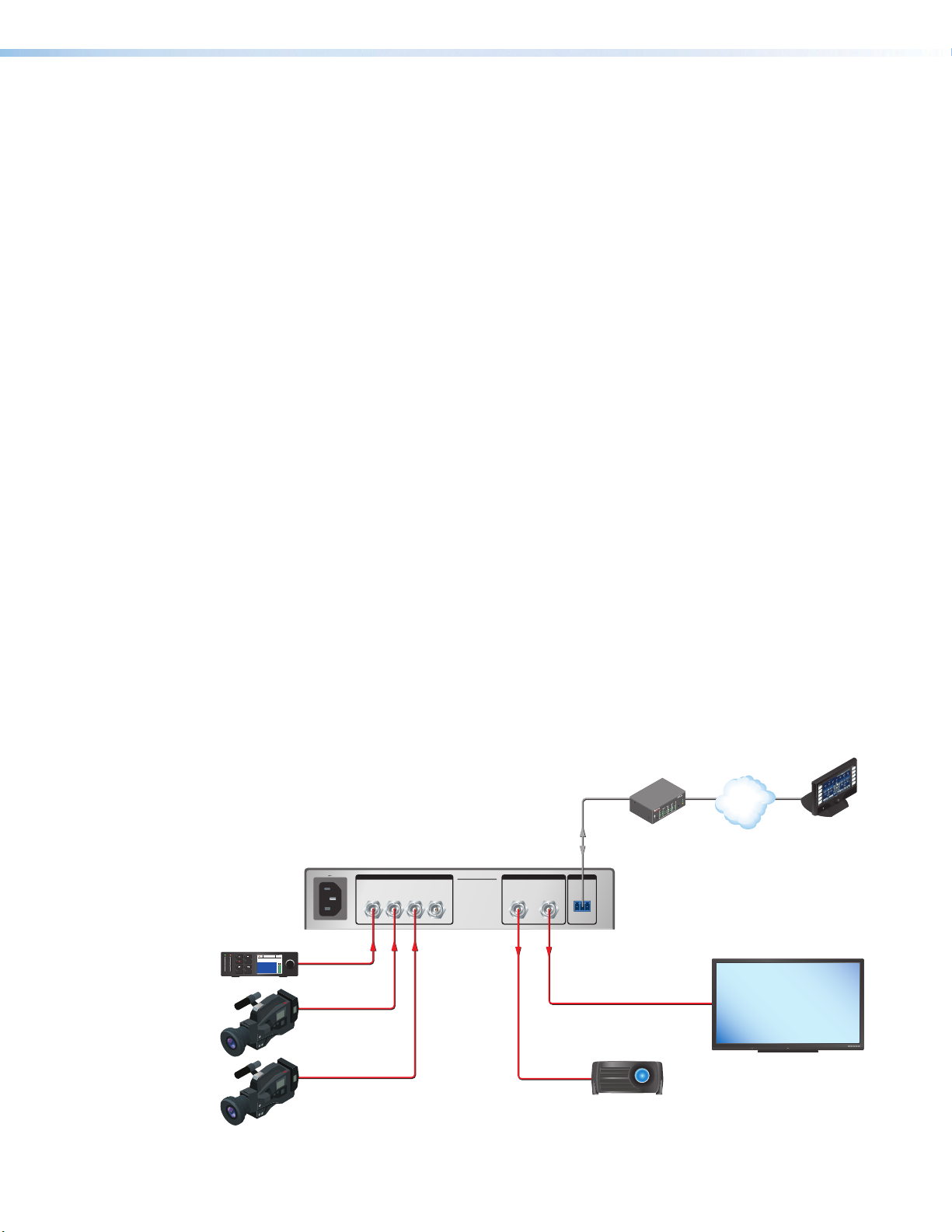
Application Diagram
The following diagram shows a typical application for a SW4 12G HD-SDI.
LAY
RE
31
NPUT
I
R
I
31
42
3
COM
RX
1
42
X
T
IPL 250
1
42
2
R
3
RS-232
Tx Rx G
IPL 250
IP Link Control
Processor
Extron
SW4 12G HD-SDI
Four Input 12G-SDI Switcher
12G-SDI
Projector
12
JOG
SETMENU
2160p30
00 : 00 : 00 : 00
1:45:24
100-240V 0.1A MAX
50-60Hz
HD-SDI
Player
12G-SDI
Cameras
RS-232
INPUTS REMOTEOUTPUTS
1234 AB
SW4 12G HD-SDI
Figure 1. SW4 HD 4K PLUS Application Diagram
VCR
DVD
OC
D
M
A
C
P
TO
LAP
PC
ON
F
F
O
SPLAY
FLAT PANEL
I
D
MUTE
N
EE
R
SC
P
U
N
EE
R
N
SC
OW
D
TouchLin
Control
System
®
100
LINK
ACT
TCP/IP
MODEL 80
12G-SDI Display
SW4 12G HD-SDI • Introduction 2
Page 11

Installation
Switcher
Receive
Transmit
Ground
RS-232
Tx Rx
DB9 connector (female)
pinout to control equipment
Computer
51
96
Pin RS-232 Function
1 —
2 Rx Receive data (+)
3 Tx Transmit data (–)
4 —
5 Gnd Signal ground
6 —
7 ——
8 ——
9 ——
—
—
—
This section describes the installation and setup of the SW4 12G HD-SDI switchers. Topics
include:
• Installation Overview
• Rear Panel Features
• Wiring for RS-232 Control
Installation Overview
To install and set up the SW4 12G HD-SDI switcher:
1. Turn off all equipment and disconnect it from the power source.
2. (Optional) Mount the switcher on a rack shelf or furniture (see Mounting the
SW4 12G HD-SDI Switcher on page 31).
3. Connect video inputs to the BNC input connectors 1 through 4 (see figure 2, B, on
the next page).
NOTE: Each input is equalized regardless of the rate.
4. Connect one or two video output devices to the BNC output connectors (C).
5. If the switcher will be connected to a computer or host controller for remote
6. Power on the input and output devices, then connect power to the switcher by
NOTE: Mirrored outputs 1 and 2 output identical signals.
configuration and control, do either of the following:
• Wire the provided 3-pole captive screw connector to an RS-232 cable. Connect
the RS-232 cable to the RS-232 port on the rear panel of the switcher and to the
host RS-232 port (see the illustration at right). Protocol for the RS-232 port is 9600
baud, 8 data bits, 1 stop bit, no parity.
• Connect a USB A to mini B cable from the computer to the front panel USB Config
port (see figure 4, B, on page 6).
connecting the provided IEC power cord to the switcher power connector (see figure 2,
) and to an AC outlet.
A
SW4 12G HD-SDI • Installation 3
Page 12
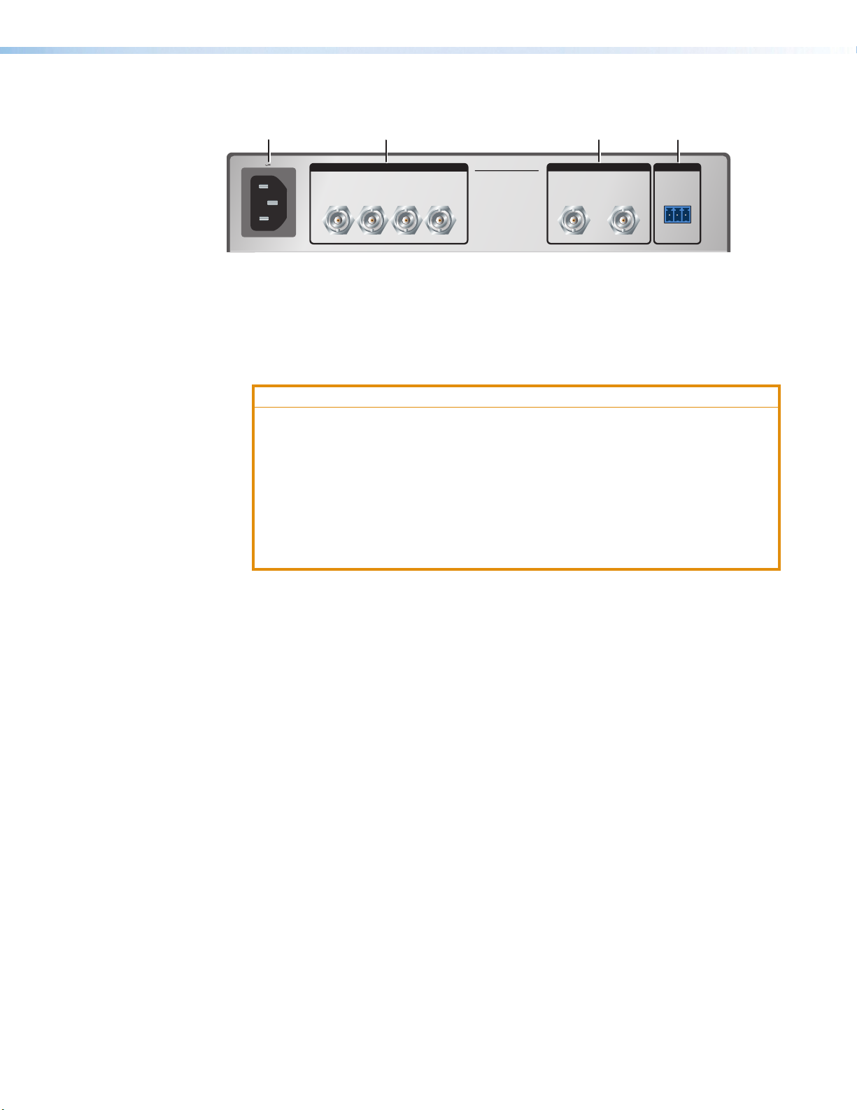
Rear Panel Features
A
100-240V 0.1A MAX
1234 AB
50-60Hz
Power connector
A
SDI input connectors
B
B
INPUTS REMOTEOUTPUTS
SW4 12G HD-SDI
Output connectors
C
RS-232 control connector
D
C
D
RS-232
Tx Rx G
Figure 2. SW4 12G HD-SDI Rear Panel
Power connector — Connect this male IEC connector to an AC power source. The
A
switcher powers on when the power cable is connected.
ATTENTION:
• The installation must always be in accordance with the applicable provisions of
National Electrical Code ANSI/NFPA 70, article 725 and the Canadian Electrical
Code part 1, section 16. The power supply shall not be permanently fixed to
building structure or similar structure.
• Cette installation doit toujours être en accord avec les mesures qui s’applique
au National Electrical Code ANSI/NFPA70, article725, et au Canadian
Electrical Code, partie1, section16. La source d’alimentation ne devra pas
être fixée de façon permanente à une structure de bâtiment ou à une structure
similaire.
SDI input connectors 1 through 4 — Connect up to four SDI video inputs to these
B
female 75 ohm BNC connectors.
Each input is equalized, regardless of the rate. The SW4 12G HD-SDI equalizes
incoming input signals with the following distances:
• Up to 230 feet (70 meters) at 11.88 Gbps
• Up to 295 feet (90 meters) at 5.94 Gbps
• Up to 590 feet (180 meters) at 2.97 Gbps
• Up to 787 feet (240 meters) at 1.485 Gbps
• Up to 300 meters (984 feet) at 270 mbps
SDI output connectors A and B — Connect one or two SDI output devices to these
C
female BNC buffered output connectors. These connectors output identical SDI signals,
buffered and reclocked.
The outputs receive and pass all ancillary data (HDR, embedded audio, closed caption,
and time code). Unknown rates are buffered but not reclocked.
The SW4 12G HD-SDI passes and distributes up to 16 channels of embedded audio at
48 kHz, 24-bit audio with video.
RS-232 connector — Use this 3-pole, 3.5 mm captive screw connector for RS-232
D
communication between the switcher and the computer.
To enable RS-232 control, connect the Tx (transmit), Rx (receive) and G (ground) pins
to the serial port of your computer (see Wiring for RS-232 Control on the next page).
The default RS-232 protocol for this port is 9600 baud, 8 data bits, 1 stop bit, and no
parity.
SW4 12G HD-SDI • Installation 4
Page 13
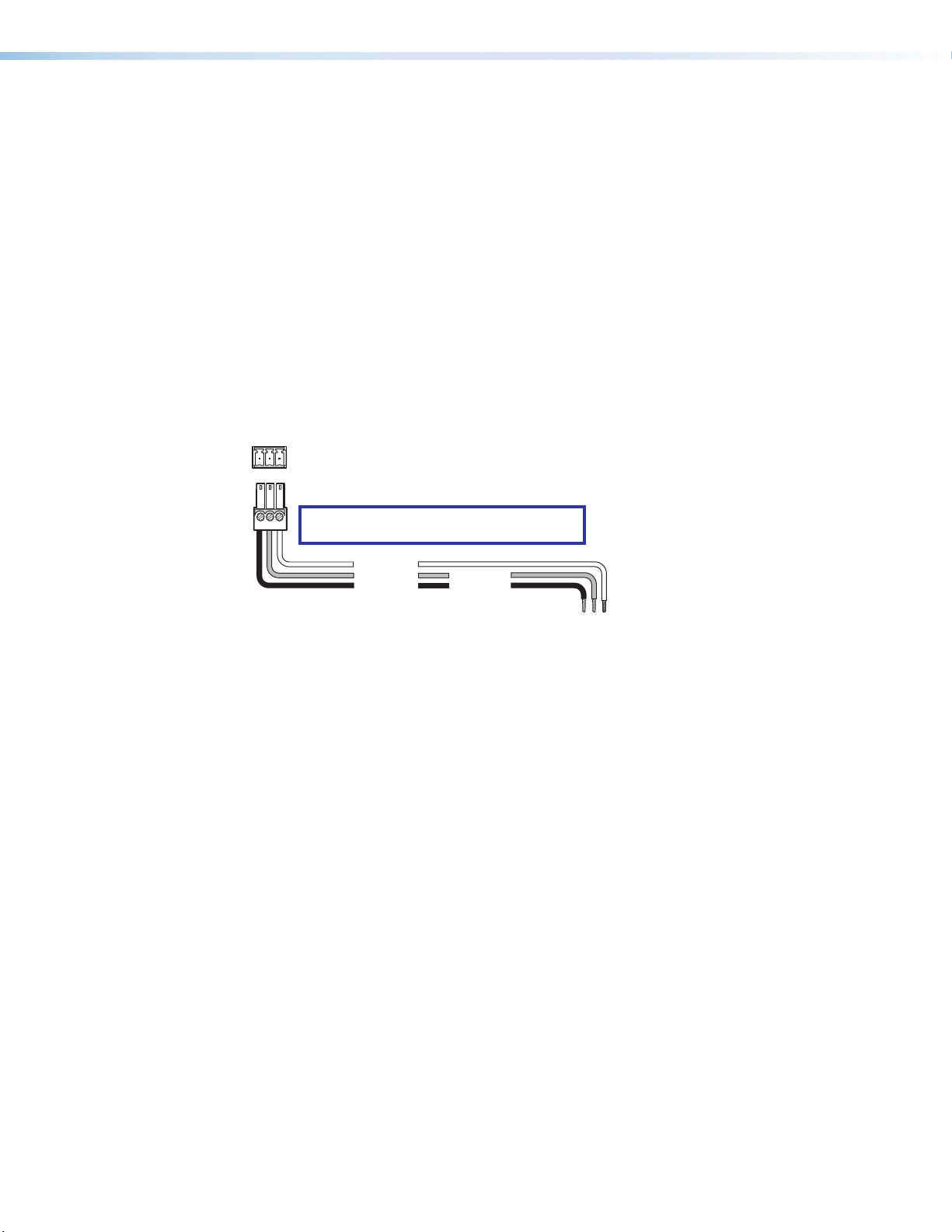
Wiring for RS-232 Control
m
RS-232 Port
RS-232
Use a female 9-pin D-to-bare wire RS-232 cable or a universal control cable (UC50' or
UC100') to connect your computer or control system to the RS-232 pins of the Remote
connector.
1. Wire the unterminated end of the RS-232 cable to the provided 3-pole captive screw
plug as described below. Connect the transmit, receive, and ground wires of the cable
to the three pins of the connector, starting at the left:
• Connect the transmit wire to pin 1 which plugs into the Tx (transmit) port.
• Connect the receive wire to pin 2 which plugs into the Rx (receive) port.
• Connect the ground wire to pin 3 which plugs into the G (ground) port.
2. Plug the 3-pole connector into the Remote receptacle on the rear panel of the switcher.
3. Connect the other end of the cable to the appropriate computer or control system
connector.
Figure 3 shows how to wire this connector for RS-232.
SW4 12G HD-SDI Switcher
Rear Panel
Tx Rx G
Remote Port
NOTE: If you use cable that has a drain wire,
tie the drain wire to ground at both ends.
Ground (G)
Receive (Rx)
Transmit (Tx)
Transmit (Tx)
Receive (Rx)
Computer or
Control Syste
Figure 3. Remote Connector Pin Assignments
SW4 12G HD-SDI • Installation 5
Page 14
Operation
This section describes the operation of the SW4 12G HD-SDI switchers. Topics include:
• Front Panel Features
• Operations
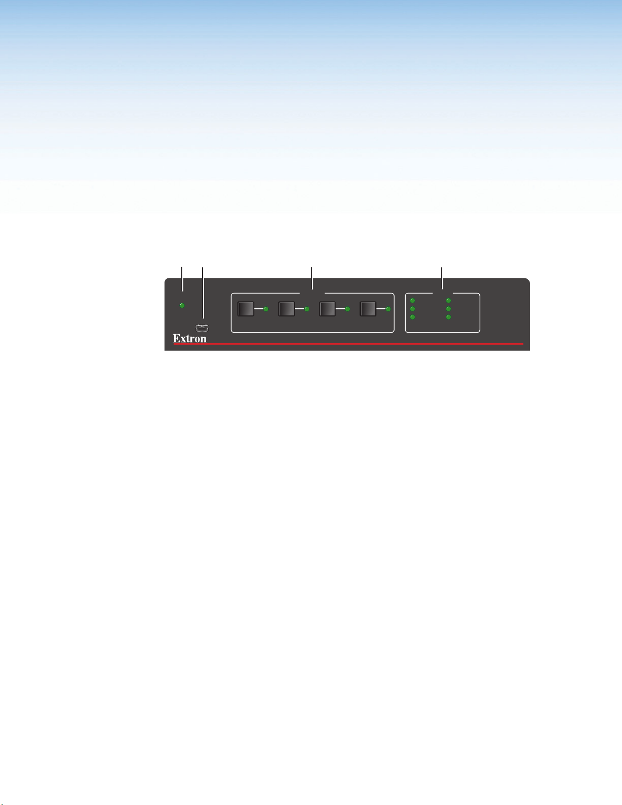
Front Panel Features
A
AUTO
SWITCH
B
CONFIG
C
1
INPUTS RATE
2 3 4
D
270 Mbps 5.94 Gbps
1.485 Gbps 11.88 Gbps
2.97 Gbps OTHER
SW4 12G HD-SDI
SDI SWITCHER
Figure 4. SW4 12G HD-SDI Front Panel
AUTO SWITCH LED — This LED lights when auto-input switching is enabled (see
A
Auto-Input Switching on page 7 for more information).
CONFIG port — Connect a USB cable (USB A to mini-B) between your computer
B
and this female USB mini-B port to configure and control the switcher via PCS or SIS
commands, and to update the firmware.
Input selection buttons and LEDs — Press one of these buttons to select an input
C
to switch to the outputs. The green LED at the right of each button lights when the
corresponding input is selected. If auto-input switching is in effect, these buttons are
disabled, but the LEDs continue to light to indicate the selected input.
Rate indicator LEDs — These six LEDs light to indicate the incoming SDI rate:
D
270 Mbps, 1.485 Gbps, 2.97 Gbps, 5.94 Gbps, 11.88 Gbps, or other. If the switcher
detects a rate other than those represented by the other five LEDs, the Other LED
lights.
When the switcher detects a valid rate on the input, the signal is equalized and
reclocked to that rate on the output. If the rate is not a valid one, the input is equalized,
but is not reclocked.
SW4 12G HD-SDI • Operation 6
Page 15

Operations
Selecting an Input
Auto-input Switching
To switch an input to the outputs, use any of the following methods:
• Front panel — Select an input by pressing the desired front input button. The LED of
the selected input lights.
NOTE: Outputs 1 and 2 output identical signals.
• PCS — See AV Controls on page 23.
• SIS commands — See the Input Selection commands on page 12.
If you are using auto-input switching, no action is necessary. The switcher automatically
switches to the highest or lowest numbered active input, depending on the configuration
(see “Auto-input Switching”).
Auto-input switching allows the SW4 12G HD-SDI to automatically select the active,
connected input based on detection of an active video signal. Using PCS or SIS commands,
you can enable or disable auto-input switching, and select the auto-input switch mode.
When auto-input switching is in effect, the green Auto Switch LED on the front panel lights
and the front panel input buttons are disabled. (The button LED for the selected input lights.)
Auto-input switch modes
By default, auto-input switching is off. To enable it, select one of the auto switch modes
using PCS (see Configuring auto-input switching on page 26) or SIS commands (see
the Auto-input Switch Mode commands on page 12). The switcher switches to the
highest- or lowest-numbered input that has an active signal.
• Highest active input — The switcher selects the active input with the highest number
(priority order 4, 3, 2, 1).
• Lowest active input — The switcher selects the active input with the lowest number
(priority order 1, 2, 3, 4).
Resetting
Resetting returns the unit to its factory-set values. To reset the switcher, use either of these
methods:
• PCS — See Resetting the Unit on page 26.
• SIS commands — Enter the
on page 14).
E
ZXXX
}
SIS command (see the Resetting command
SW4 12G HD-SDI • Operation 7
Page 16

Locking the Front Panel (Executive Mode)
To prevent front panel input buttons being pressed accidentally or by unauthorized users,
you can place the switcher in front panel lock mode.
To toggle lock mode on and off, use any of the following methods:
• Press and hold the Input 1 and Input 2 buttons simultaneously, until all front panel LEDs
blink three times (approximately 5 seconds).
• PCS — See Enabling and disabling front panel lockout on page 26.
• SIS commands — See the Front Panel Lockout (Executive Mode) commands on
page 12.
If an input button is pressed while the switcher is in front panel lock mode, all front panel
LEDs blink once, then the switcher reverts to the currently selected input.
NOTE: RS-232 and USB communication remain enabled while the switcher is in lock
mode.
SW4 12G HD-SDI • Operation 8
Page 17

SIS Configuration and Control
This section describes remote operation of the SW4 12G HD-SDI switchers. Topics include:
• Using Simple Instruction Set (SIS) Commands
• Command and Response Table for SIS Commands
Using Simple Instruction Set (SIS) Commands
The SW4 12G HD-SDI can be remotely set up and controlled via Extron SIS commands that
are issued from a host computer or other device, such as a control system. SIS commands
can be issued via RS-232 from the computer serial port to the switcher rear panel Remote
port (see Wiring for RS-232 Control on page5) or USB from a computer USB port to the
switcher front panel Config port.
Host-to-switcher Communications
SIS commands consist of one or more characters per field. No special characters are
required to begin or end a command sequence. You can enter these commands from your
computer using a communication software program such as Extron DataViewer. When
the switcher determines that a command is valid, it executes the command and sends a
response to the host device.
Responses from the SW4 12G HD-SDI to the host computer end with a carriage return and
a line feed (CR/LF = ]), which signals the end of the response character string. A string is
one or more characters.
Switcher-initiated Messages
When a local event such as a front panel selection or change in signal status takes place,
the switcher responds by sending a message to the host, indicating what change has
occurred. No response is required from the host.
The switcher sends the following message when it is first powered on:
(C) Copyright 20nn, Extron Electronics, SW4 12G HD-SDI, Vn.nn, 60-1683-01
20nn is the year in which the copyright for the firmware was registered, and Vn.nn is the
firmware version number
SW4 12G HD-SDI • SIS Configuration and Control 9
Page 18

Error Responses
Space
If the switcher is unable to execute a command it receives because the command is invalid
or contains invalid parameters, the switcher returns an error response to the host. The
following error response codes can be sent:
E01 – Invalid input channel (out of range)
E06 – Invalid input during auto-input switching
E10 – Invalid command
E13 – Invalid value (out of range)
Using the Command and Response Table
The Command and Response Table for SIS Commands, starting on page 12, lists
valid ASCII and hexadecimal command codes, the switcher responses to the host, and a
description of the command function or the results of executing the command.
The conversion table below is for use with the command and response table.
ASCII to Hex Conversion Table
•
Figure 5. ASCII to Hex Conversion Table
SW4 12G HD-SDI • SIS Configuration and Control 10
Page 19

Symbol Definitions
]
= CR/LF (carriage return with line feed) (hex 0D 0A)
}
or | = Soft carriage return (no line feed)
•
= Space
E
or W = Escape
NOTE: Unless otherwise indicated, commands are not case-sensitive.
X!
= Input number
0 through 4
0 = Deselect (mute) all inputs (disable outputs)
X@
= Video mute
0 = Unmute video (default)
1 = Mute video
X#
= Auto-input switch mode
0 = Disabled — Manual switching (default)
1 = Enabled —
2 = Enabled —
X$
= Front panel lock (executive mode)
0 = Off or disabled (default)
1 = On or enabled
X%
= Unit name. The name can have up to 24 alphanumeric characters including hyphens (-),
with no spaces. The first character must be a letter, and the last character cannot be a
hyphen. The default is SW4-12G-HD-SDI.
X^
= Verbose mode
0 = None
1 = Verbose mode (default)
2 = Tagged responses for queries
3 = Verbose mode and tagged responses for queries
NOTES:
• In verbose response mode, the switcher responds with unsolicited responses
for value and setting changes that may result from a signal change, or a setting
adjustment made via another interface.
• For example, the switcher can send out a notice of a change in some setting without
receiving a query via a PC or a control system. That change could have been a result
of an internal process, a selection made from the front panel, or a selection made via
PCS. This is an example of a verbose (wordy) relationship between the controller and a
connected device.
• If tagged responses are enabled, all View type commands return the command
string plus the data, the same as in responses for setting a value. For example:
Command: E CN
Response: Ipn • X% ] (tagged response)
or X% ] (untagged response)
The switcher selects the active input with the highest number.
The switcher selects the active input with the lowest number.
}
X&
= Input signal presence
0 = No signal present
1 = Signal present
X*
= Reclocker rate
0 = Automatic mode
1 = 11.88 Gbps
2 = 5.94 Gbps
3 = 2.97 Gbps
4 = 1.485 Gbps
5 = 270 Mbps
X(
= Firmware version numer, expressed to the second decimal place
SW4 12G HD-SDI • SIS Configuration and Control 11
Page 20

Command and Response Table for SIS Commands
Command
ASCII Command
(Host to Switcher)
Response
(Switcher to Host)
Input Selection
Select input (audio and
video)
View input
KEY:
X!
= Input number 0 through 4
0 = Deselect all inputs (disable output)
X!
! InX!•All
!
X!]
]
Muting
Video mute
View video mute status
KEY:
X@
= Video mute setting 0 = Unmute (default), 1 = mute
X@
B Vmt
B
X@]
X@]
Reclocking
Set output reclocker rate
Query output reclocker =
KEY:
X*
= Reclocker rate 0 = Automatic mode, 1 = 11.88 Gbps, 2 = 5.94 Gbps, 3 = 2.97 Gbps,
4 = 1.485 Gbps, 5 = 270 Mbps
X*
= Rte
X*]
X*]
Auto-input Switch Mode
Set the auto-input switch
mode
View auto-input switch mode
EX#
E
AUSW
}
AUSW
} X#]
Ausw
X#]
Additional Description
Select input X!.
View the selected input (X!).
Mute the video signal.
Show video mute status X@.
Set the reclocker rate to X*.
View the reclocker rate.
Set the auto-input switch mode
to X#.
View current auto-input switch
mode X#.
KEY:
X#
= Auto-input switch mode 0 = Disabled — Manual switching (default)
1 = Enabled — The switcher selects the active input with the highest
number.
2 = Enabled — The switcher selects the active input with the lowest
number.
Signal Presence
1
2
3
Request status and
reclocker rate of all signals
KEY:
X&
= Input and output signal status 0 = No signal detected (default), 1 = Signal detected
X*
4 = 1.485 Gbps, 5 = 270 Mbps
= Reclocker rate 0 = Automatic mode, 1 = 11.88 Gbps, 2 = 5.94 Gbps, 3 = 2.97 Gbps,
E
} X&
LS
X&
•
•
In verbose modes 2 and 3:
1
X&
Sig
•
X&
X&
4
X&
X*]
•
*
2
3
4
X&
X&
•
X*]
•
*
View the signal presence X& and
reclocker rate X* of all inputs.
Front Panel Lockout (Executive Mode)
Enable or disable lock mode
View lockout status
KEY:
X$
= Front panel lock mode 0 = Lock mode off (default), 1 = Lock mode on
X$
X Exe
X
X$]
X$]
Select front panel lock mode X$.
Show lock mode status X$.
SW4 12G HD-SDI • SIS Configuration and Control 12
Page 21

Command
Unit Name
Set unit name
Set name to factory default
View unit name
ASCII Command
(Host to Switcher)
EX%CN}
E
}
•CN
Response
(Switcher to Host)
Ipn•
Ipn•SW4-12G-HD-SDI
ECN} X%]
X%]
Additional Description
Assign name X% for the switcher.
]
Show the current switcher name
X%
KEY:
X%
= Unit name Consists of up to 24 alphanumeric characters, including the hyphen (-).
Information Requests
Request information
Query model name
Query model description
Query part number
Query firmware version
Example:
Query firmware version and
build
Query detailed firmware
version
I
1I
2I
N
Q
Q
*Q
0Q
InX!•VmtX@•AuswX#•Rte
SW4-12G-HD-SDI
In verbose modes 2 and 3:
Inf01*SW4-12G-HD-SDI
12G•SDI•SWITCHER
In verbose modes 2 and 3:
Inf02*12G•SDI•SWITCHER
60-1683-01
In verbose modes 2 and 3:
Pno•60-1683-01
]
]
]
X*]
]
]
X(]
In verbose modes 2 and 3:
X(]
Ver
]
1.01
n.nn.nnnn
In verbose modes 2 and 3:
Bldn.nn.nnnn
n.nn.nnnn
In verbose modes 2 and 3:
Vern.nn.nnnn
]
]
]
]
View selected input X!, video
mute status X@, auto-input switch
mode X#, and reclocker rate X*.
Show the switcher model name.
]
Show the switcher model and
signal type.
Show the part number of the
switcher.
Show firmware version number X(,
to the second decimal place.
Show the firmware version and
build number.
Show complete firmware version
number.
KEY:
X!
= Input number 0 through 4. 0 = no input selected.
X@
1 = Enabled — The switcher selects the active input with the highest
number.
2 = Enabled — The switcher selects the active input with the lowest
number.
3 = 2.97, Gbps, 4 = 1.485 Gbps, 5 = 270 Mbps
= Video mute setting 0 = Unmute (default), 1 = mute
X#
= Auto-input switch mode 0 = Disabled — Manual switching (default)
X&
= Input and output signal status 0 = No signal detected (default), 1 = Signal detected
X*
= Reclocker rate 0 = Automatic mode, 1 = 11.88 Gbps, 2 = 5.94 Gbps,
X(
= Firmware version Displayed to the second decimal place.
SW4 12G HD-SDI • SIS Configuration and Control 13
Page 22

Command
Verbose Mode
Set verbose mode
View verbose mode
ASCII Command
(Host to Switcher)
EX^CV}
Response
(Switcher to Host)
Vrb
ECV} X^]
In verbose modes 2 and 3:
Vrb
X^]
X^]
Additional Description
Set the verbose mode to X^
View current verbose mode X^.
KEY:
X^
= Verbose mode 0 = None
1 = Verbose mode (default for USB and RS-232 connections)
2 = Tagged responses for queries
3 = Verbose mode and tagged responses for queries
See the Verbose mode symbol definition for details on these modes.
Resetting
Reset all device settings to
factory defaults
E
ZXXX
}
Zpx
]
Reset product-specific settings to
factory default values. Does not
affect IP settings or user files.
SW4 12G HD-SDI • SIS Configuration and Control 14
Page 23

Software Configuration and Control
The Extron Product Configuration Software offers another way to control the switcher via
USB. The graphical interface includes some of the same functions as those available via the
device front panel and SIS commands. PCS is compatible with most Microsoft® Windows
operating systems. The software is available at www.extron.com.
This section provides instructions for obtaining and using PCS. The following topics are
included:
• Downloading and Installing PCS
• Starting PCS
• Using PCS
Downloading and Installing PCS
To download PCS from the Extron website, locate it on the Download Center page or go
to the PCS product page.
Downloading PCS from the Download Center Page
Figure 6. Download Tab and Software Button on the Download Screen
SW4 12G HD-SDI • Software Configuration and Control 15
Page 24

1. On the Extron website, select the Download tab (see figure 6, 1, on the previous
page), then click the Software button (2).
Alternatively, hover the mouse pointer over the Download tab, then move the pointer to
the Software link in the Downloads column and click it.
2. Click the P link (see figure7, 1).
Figure 7. PCS Link on Download Center Screen
3. Locate PCS on the list of available software programs and click the Download link (2)
to the far right of the name.
4. If a login page appears, fill in the required information to log into the www.extron.com
website (if you need an ID number, see your Extron representative).
If no login page appears, skip to step 7.
5. Follow the instructions on the subsequent screens to complete the software program
installation.
6. Submit any required information to start the download.
7. Double-click on the icon for the executable (.exe) file at the bottom of the page.
8. Follow the instructions that appear on the screen to install the program.
NOTE: By default, the installation creates a folder on your computer at:
C:\Program Files (x86)\Extron\Extron PCS
SW4 12G HD-SDI • Software Configuration and Control 16
Page 25

Installing Using the PCS Product Page
To install PCS using the Extron website PCS product page:
1. From the Product Shortcuts dropdown menu, select PCS.
Figure 8. Product Shortcuts Menu on the Extron Website
The PCS product page opens (see figure 9 on the next page).
SW4 12G HD-SDI • Software Configuration and Control 17
Page 26

Figure 9. PCS Product Page
1. In the Power Search field (see figure9, 1), type PCS. A drop-down menu of selected
search results appears under the field.
2. Press <Enter> on the keyboard or select PCS from the drop-down menu.
3. Click the Download button (2).
4. If a login page appears, fill in the required information to log into the www.extron.com
website (if you need an ID number, see your Extron representative).
If no login page appears, skip to step 7.
5. Follow the instructions on the subsequent screens to complete the software program
installation.
NOTE: By default, the installation creates a folder on your computer at:
C:\Program Files (x86)\Extron\Extron PCS
SW4 12G HD-SDI • Software Configuration and Control 18
Page 27

Starting PCS
Start PCS as follows:
1. Ensure the computer is connected to the USB port on the switcher front panel.
2. Click Start > Programs > Extron Electronics > Extron Product Configuration
Software > Extron Product Configuration Software. The Product Configuration
Software opens with the Device Discovery window (see figure10).
Figure 10. Device Discovery Window
3. Select your SW4 12G HD-SDI device USB port (see figure10, 1)
4. Click Connect (2). The Product Configuration Software main window opens (see
figure 11 on the next page).
SW4 12G HD-SDI • Software Configuration and Control 19
Page 28

Using PCS
Main Window Overview
PCS enables you to perform configuration tasks, such as selecting and muting inputs,
enabling and disabling auto-input switching and front panel lockout, and updating firmware.
When a connection is established between PCS on the computer and the switcher, the
main window opens.
Main Device tab
1
Device tab
2
Figure 11. Main Window
The main window has the following components:
Main device tab — Contains a plus (+) button, which displays the Device Discovery
1
screen when another device screen is already displayed. It also has a down arrow
button, which displays a configuration drop-down menu. For more information about
this tab, see the main PCS Help File, accessible from the PCS menu (see figure 11, 5).
Device tabs — (More than one tab can be displayed) These tabs contain the names
2
of devices that are either connected to the computer (via USB or TCP/IP) or have been
selected for viewing offline.
• If a device is online, connected to the computer, the circle in front of the name on its
tab is green. If a device is offline, the circle is gray.
• Each device tab contains a down arrow button, which opens the Device menu.
From this menu, you can disconnect from the switcher, view certain hardware
settings, reset the switcher to factory defaults, rename the switcher, update
firmware, and view information about the SW4 12G HD-SDI PCS module. See
Device menu on the next page for explanations of these items.
• When you hover the mouse pointer over a tab, an X in a circle appears on the tab.
Click the X to disconnect from the device and close its window.
AV Controls panel
3
General Settings panel
4
SW4 12G HD-SDI • Software Configuration and Control 20
PCS menu icon
5
Page 29

AV Controls panel — In this panel you can select (switch) an input, and mute and
3
unmute the audio and video signal. To collapse and hide this panel, click the arrow
button in the upper-right corner of the panel.
For a description of the components of this panel, see AV Controls on page 23.
General Settings panel — This panel contains a Hardware Settings button, which
4
you can click to view information about your SW4 12G HD-SDI unit and to change its
device name. It also contains the controls that enable you to select the reclocker rate,
lock or unlock the front panel, and enable and set priorities for auto-input switching.
PCS menu icon — Click this icon to display the PCS menu, from which you can open
5
the general PCS help file, open the PCS introductory tutorial, expand or collapse the
text on the device tabs to display or hide the device IP addresses (TCP/IP connection
only), enable and disable certain dialog boxes that appear in response to actions, check
the software version number, and exit the PCS program (see PCS menu on the next
page for a description of these items).
Menus
The main window contains two drop-down menus: the Device menu and the PCS menu.
You can access these menus by clicking the appropriate icons.
Device menu
To display the Device drop-down menu for your
switcher, click the down arrow on its device tab. The
menu contains the following items:
• Disconnect — Disconnects the switcher from the
computer. You can still click the configuration buttons
to display the pages, but all interactive fields are
disabled.
• Settings — Displays the Hardware Settings submenu, which opens the Hardware
Settings dialog box. This screen enables you to view information about the unit,
including the part number, model name, model description, and firmware version. You
can also edit the device name (see Viewing and configuring hardware settings on
page 24 for details).
• Reset Device — Opens a Reset Device screen on which you can initiate a switcher
reset to factory defaults (see Resetting the Unit on page 26 for more information).
• Update Firmware — Displays the Update Firmware to this Device submenu, from
which you can select to upload a new firmware version to the switcher (see Updating
Firmware using PCS on page 27 for the procedure).
• About This Module — Opens the
dialog box shown at right, which
displays the part number and
version of the switcher module of
PCS.
SW4 12G HD-SDI • Software Configuration and Control 21
Page 30

PCS menu
To display the PCS drop-down menu, click the PCS menu
icon in the upper-right corner of the main window (see
figure 11, 5, on page 20).
The PCS menu contains items that provide information
about PCS, of which the SW4 12G HD-SDI module is a
part. It contains the following items:
• Show Expanded Device Tabs — Expands or
collapses the text on the device tabs to show or hide
the switcher USB connection.
• Software Settings — Opens a screen that allows you to enable all confirmation dialog
boxes (see the Extron PCS Help File for more information).
• Tutorial — Opens a screen that shows what the items on the menu bar are used for.
This screen appears when PCS is opened, unless you click the OK button to disable it.
• Extron PCS Help — Opens the general PCS help file, which provides information on
the basic PCS program. It does not discuss specific devices such as SW4 12G HD-SDI.
• About Extron PCS — Opens the About - Extron PCS window, which provides
information about the current PCS software, including version number and part number.
Figure 12. About PCS Window
At the bottom of this window, you can click the Details button to view all the modules
within the software, and the Licenses button to view the PCS licenses. To close this
window, click OK.
• Exit — Closes PCS.
SW4 12G HD-SDI • Software Configuration and Control 22
Page 31

AV Controls
The AV Controls panel of the main window enables
you to switch inputs and mute or unmute video and
audio signals. The buttons in this panel are not available
if the computer is not connected to a switcher (see
Starting PCS on page 19).
The AV Controls panel contains the following:
AV Inputs buttons — Click these buttons to select
1
or switch inputs. The buttons also show input
connection status: selected or source connected
(see Selecting an Input for details).
AV Mute button — Click this button to mute and
2
unmute the audio and video signals.
Expand and Collapse button — Click this left arrow button to expand or hide the AV
3
Controls panel. The panel is reduced to a bar at the left edge of the main window.
When the panel is collapsed, the arrow at the top of the bar points right. To redisplay
the panel, click the right arrow button.
General Settings
The General Settings panel provides configurable settings for the front panel lock mode
(executive mode), auto-input switching, and reclocking. It also contains the Hardware
Settings button, which lets you open the Hardware Settings screen.
Figure 13. General Settings Panel
SW4 12G HD-SDI • Software Configuration and Control 23
Page 32

The following functions are available from the General Settings panel:
Viewing and configuring hardware settings
To access the hardware settings screen, click the Hardware Settings button (see
figure 13, 1, on the previous page) to open the Hardware Settings screen (you can also
access this screen by selecting Settings>Hardware Settings from the Device menu).
This screen has two side tabs. It opens with the Unit Information tab (see figure 14, 1)
selected.
Figure 14. Hardware Settings Screen
• Unit Information —This screen contains view-only information about the
SW4 12G HD-SDI: part number, model name, model description, and the firmware
version.
SW4 12G HD-SDI • Software Configuration and Control 24
Page 33

• Device Name — Select the Device Name tab (see figure 15, 1) to view and edit the
name of the connected SW4 12G HD-SDI switcher.
Figure 15. Device Name Screen
• To edit the device name, click in the Enter a Device Name field (2) and type the
new name (only letters, numbers, and the hyphen (-) can be used in this field).
When finished, click Apply (4).
• To reset the device name to its factory default (SW4-12G-HD-SDI) click Reset to
Default (
• Click Cancel to close the window without making any changes.
3
).
Selecting the reclocker rate
To set the reclocker rate, select the desired rate from the drop-down menu. The default is
Other.
Figure 16. Reclocker Rate Menu
SW4 12G HD-SDI • Software Configuration and Control 25
Page 34

Enabling and disabling front panel lockout
In the Front Panel Lockout (Exec Mode) panel, select the desired radio button:
Figure 17. Front Panel Lockout Panel
• Unlock Front Panel (default) — The front panel input buttons are available to any user
for input selection.
• Lock Front Panel — The front panel input selection buttons are disabled.
When a lock mode button is selected (changing the mode), all LEDs on the front panel blink
three times.
Configuring auto-input switching
To enable auto-input switching, select the Enable Auto Switch checkbox in the Auto
Switch panel.
Figure 18. Auto Switch Panel
To select the auto-input switching priority, select one of the following radio buttons:
• Priority to Highest Active Input Number — The switcher selects the active input
with the highest number.
• Priority to Lowest Active Input Number — The switcher selects the active input
with the lowest number.
Resetting the Unit
To reset the SW4 12G HD-SDI to its factory defaults while retaining the current firmware
version:
1. From the Device menu, select Reset Device. The following window opens.
Figure 19. Reset Device Screen
SW4 12G HD-SDI • Software Configuration and Control 26
Page 35

2. On the Reset Device screen, click the Reset button (see figure 19, 1, on the
previous page), to continue the reset.
When the reset is complete, a Settings Reset message appears at the top of the
General Settings screen and the Reset Device screen closes.
Updating Firmware using PCS
If you are notified that new firmware is available for your switcher, download the firmware
file from the Extron website and install it on your computer. You can then upload the new
version of firmware to the switcher using PCS.
To find out the version of firmware currently loaded on your SW4 12G HD-SDI, select
Settings>Hardware Settings from the Device menu to display the Unit Information
screen (see figure 20, 1).
Figure 20. Firmware Version on Unit Information Screen
Alternatively, select the General Settings tab and click the Hardware Settings button.
If a newer firmware version is available, download the latest firmware file for the switcher to
your computer (see Downloading the SW4 12G HD-SDI firmware on the next page).
SW4 12G HD-SDI • Software Configuration and Control 27
Page 36

Downloading the SW4 12G HD-SDI firmware
To obtain the latest version of firmware for the SW4 12G HD-SDI:
1. Go to www.extron.com, hover the mouse pointer over the Download tab at the top of
the page (see figure 21, 1), then slide the pointer to the Downloads column, and click
the Firmware link (2).
Figure 21. Firmware Link on the Download Tab
2. On the Download Center screen, click one of the S links (see figure 22, 1).
Figure 22. Download Center Page for Firmware
SW4 12G HD-SDI • Software Configuration and Control 28
Page 37

3. Scroll to locate the SW4 12G HD-SDI firmware, and click the Download link at the right.
4. On the login page that appears next, fill in the required information to log into the
www.extron.com website (if you need an Extron Insider ID number, see your Extron
representative).
5. Follow the instructions on the subsequent screens to complete the firmware installation.
6. Follow the instructions on the rest of the download screens to save the executable
firmware file to your computer. Note the folder to which the file was saved.
NOTE: When downloaded from the Extron website, by default the firmware file is
placed at C:\Program Files (x86)\Extron\Firmware\SW4 12G HD-SDI.
Uploading the firmware file
1. From the PCS device tab drop-down menu, select Update Firmware>Update
Firmware to this Device.
Figure 23. Selecting Update Firmware from the Device Menu
The following prompt appears:
Figure 24. Update Firmware Confirmation Prompt
2. Click Continue. The Update Firmware to this Device dialog box opens. Click Open
Firmware File (see figure 25,
1
).
Figure 25. Open Firmware File Button
SW4 12G HD-SDI • Software Configuration and Control 29
Page 38

3. In the Firmware Files window, locate and select the desired firmware file, and click
Open.
NOTE: Only valid SW4 12G HD-SDI firmware files with an .s19 extension are
accepted.
Figure 26. Firmware Files Window
4. The Firmware File window closes and the path to the selected firmware file appears
in the Update Firmware to this Device window (see figure 27, 1).
Figure 27. Update Button
5. Click Update (2). The Update Firmware to this Device window displays a progress
bar showing the percent of the upload completed.
6. When the firmware update is complete, the SW4 12G HD-SDI main window closes and
following window appears in front of the Device Discovery window. Click Close on
the prompt.
Figure 28. Update Successful Window
7. The next prompt tells you to reconnect with the SW4 12G HD-SDI using the Device
Discovery window. Click Close on this prompt and reconnect PCS to the switcher.
SW4 12G HD-SDI • Software Configuration and Control 30
Page 39

Reference Information
Mounting the SW4 12G HD-SDI Switchers
The SW4 12G HD-SDI switchers can be set on a table, mounted on a rack shelf, or
mounted under a desk, podium, or table.
ATTENTION:
• Installation and service must be performed by authorized personnel only.
• L’installation et l’entretien doivent être effectués uniquement par un technicien
qualifié.
Tabletop Use
Four self-adhesive rubber feet are included with the SW4 12G HD-SDI units. For tabletop
use, attach one foot at each corner on the bottom of the unit, and place the switcher where
desired.
Rack Mounting
The SW4 12G HD-SDI units can be mounted on a 9.5-inch, 6-inch, or 3.5-inch deep rack
shelf. They can also be mounted vertically to the front or back rack support. For mounting
procedures, see the instructions provided with the mounting option.
UL rack mounting guidelines
The following Underwriters Laboratories (UL) guidelines pertain to the safe installation of the
equipment in a rack.
1. Elevated operating ambient temperature — If the equipment is installed in a closed
2. Reduced air flow — Install the equipment in a rack so the amount of air flow required
3. Mechanical loading — When mounting the equipment in the rack, ensure that uneven
4. Circuit overloading — When connecting the equipment to the supply circuit, consider
5. Reliable earthing (grounding) — Maintain reliable grounding of rack-mounted
or multi-unit rack assembly, the operating ambient temperature of the rack environment
may be greater than room ambient temperature. Therefore, install the equipment in
an environment compatible with the maximum ambient temperature (TMA = +122 °F,
+50°C) specified by Extron.
for safe operation of the equipment is not compromised.
mechanical loading does not cause a hazardous condition.
the effect that circuit overloading might have on overcurrent protection and supply
wiring. Consider equipment nameplate ratings when addressing this concern.
equipment. Pay particular attention to supply connections other than direct connections
to the branch circuit (for example, use of power strips).
SW4 12G HD-SDI • Reference Information 31
Page 40

Furniture Mounting
The SW4 12G HD-SDI switchers can be mounted under a desk, table, or podium using an
under-desk mounting kit (see the mounting instructions provided with the kit).
Updating Firmware using Firmware Loader
The Firmware Loader program enables you to upload new versions of firmware to your
SW4 12G HD-SDI. The program also provides a means of uploading firmware files to
multiple devices simultaneously. When you are notified that new firmware is available for
your switcher, download the firmware file from the Extron website and install it on your
computer (see Downloading the SW4 12G HD-SDI Firmware on page 28). You can then
upload the new version of firmware to the switcher.
Before updating any Extron product to the latest revision level, be sure to read the supplied
release notes or contact Extron Technical Support to determine if your product requires a
firmware update.
Downloading Firmware Loader
To obtain this software from the Extron website:
1. On the Extron website, select the Download tab (see figure 29, 1).
Figure 29. Software Link on the Download Page
2. Click the Software link (2) in the Downloads column.
SW4 12G HD-SDI • Reference Information 32
Page 41

3. On the Download Center page, click the F link (see figure 30, 1) at the top or bottom
of the screen.
Figure 30. Firmware Loader Link on Download Center Page
4. Locate Firmware Loader on the software products list, and click the Download link
(2) at the far right.
5. If a login page that appears next, fill in the required information to log into the
www.extron.com website (if you need an Extron Insider ID number, see your Extron
representative).
If you have previously logged in to this website and entered your ID, the login screen
does not appear. The executable Firmware Loader installer icon appears at the bottom
of the screen.
6. Click the installer icon and follow the instructions on the subsequent screens to install
Firmware Loader on your PC.
NOTE: When downloaded from the Extron website, by default the Firmware Loader
files are placed at C:\Program Files (x86)\Extron\FWLoader.
SW4 12G HD-SDI • Reference Information 33
Page 42

Updating Firmware Using Firmware Loader
To use Firmware Loader to upload a new firmware file to your unit:
1. Open the Firmware Loader via your desktop Start menu by making the following
selections:
Start>All Programs>Extron Electronics>Firmware Loader>Firmware Loader
2. The Firmware Loader window opens, with the Add Device dialog box displayed in
front of it.
3. From the Device Name drop-down menu (see figure 31, 1), select SW4 12G HD-SDI.
4. Click Connect (2). If the connection is successful, SW4 12G HD-SDI √ is displayed in
green in the Connected Device panel (3).
Figure 31. Successful Connection to SW4 12G HD-SDI via Firmware Loader
5. Click Add (4) at the bottom of the dialog box. The Add Device window closes, and the
SW4 12G HD-SDI information is added to the Device panel of the Firmware Loader
dialog box.
6. Double click on <double click to set> in the New Firmware File column.
SW4 12G HD-SDI • Reference Information 34
Page 43

7. In the Choose Firmware File window, browse to locate the new firmware file, select it
(see figure 32, 1), and click Open (2).
NOTES:
• When downloaded from the Extron website, by default the firmware is placed at
C:\Program Files (x86)\Extron\Firmware\SW4 12G HD-SDI.
• The firmware file must have a .s19 extension. Attempting to upload a file with a
different extension could cause the device to stop functioning.
Figure 32. Choose Firmware File Window
8. In the Firmware Loader dialog box, click Begin (see figure 33, 1).
Figure 33. Firmware Upload in Progress
The following indicators show the progress of the update:
• The Transfer Time panel shows the amounts of remaining and elapsed time for
the update (2).
• The Total Progress panel (3) displays a progress bar with Uploading above it.
• In the Devices panel (4), the Progress column displays an incrementing
percentage and another progress bar. The Status column displays Uploading.
9. The upload is complete when the Remaining Time panel shows 00.00.00, the
Progress column shows 100%, and Completed is displayed above the progress bar
and in the Status column. Close the Firmware Loader dialog box.
SW4 12G HD-SDI • Reference Information 35
Page 44

Extron Warranty
Extron Electronics warrants this product against defects in materials and workmanship for a period of three years
from the date of purchase. In the event of malfunction during the warranty period attributable directly to faulty
workmanship and/or materials, Extron Electronics will, at its option, repair or replace said products or components,
to whatever extent it shall deem necessary to restore said product to proper operating condition, provided that it is
returned within the warranty period, with proof of purchase and description of malfunction to:
USA, Canada, South America,
and Central America:
Extron Electronics
1230 South Lewis Street
Anaheim, CA 92805
U.S.A.
Europe and Africa:
Extron Europe
Hanzeboulevard 10
3825 PH Amersfoort
The Netherlands
Asia:
Extron Asia Pte Ltd
135 Joo Seng Road, #04-01
PM Industrial Bldg.
Singapore 368363
Singapore
This Limited Warranty does not apply if the fault has been caused by misuse, improper handling care, electrical
or mechanical abuse, abnormal operating conditions, or if modifications were made to the product that were not
authorized by Extron.
NOTE: If a product is defective, please call Extron and ask for an Application Engineer to receive an RA (Return
Authorization) number. This will begin the repair process.
USA: 714.491.1500 or 800.633.9876 Europe: 31.33.453.4040
Asia: 65.6383.4400 Japan: 81.3.3511.7655
Japan:
Extron Electronics, Japan
Kyodo Building, 16 Ichibancho
Chiyoda-ku, Tokyo 102-0082
Japan
China:
Extron China
686 Ronghua Road
Songjiang District
Shanghai 201611
China
Middle East:
Extron Middle East
Dubai Airport Free Zone
F13, PO Box 293666
United Arab Emirates, Dubai
Units must be returned insured, with shipping charges prepaid. If not insured, you assume the risk of loss or damage
during shipment. Returned units must include the serial number and a description of the problem, as well as the
name of the person to contact in case there are any questions.
Extron Electronics makes no further warranties either expressed or implied with respect to the product and its quality,
performance, merchantability, or fitness for any particular use. In no event will Extron Electronics be liable for direct,
indirect, or consequential damages resulting from any defect in this product even if Extron Electronics has been
advised of such damage.
Please note that laws vary from state to state and country to country, and that some provisions of this warranty may
not apply to you.
Contact Information
Worldwide Headquarters: Extron USA West, 1025 E. Ball Road, Anaheim, CA 92905, 800.633.9876
 Loading...