

Page 1

SW2 DP
DisplayPort Switcher
User Guide
DisplayPort Switchers
68-2245-01 Rev. B
10 17
Page 2

Safety Instructions
Safety Instructions • English
WARNING: This symbol, , when used on the product, is intended to
alert the user of the presence of uninsulated dangerous voltage within
the product’s enclosure that may present a risk of electric shock.
ATTENTION: This symbol, , when used on the product, is intended
to alert the user of important operating and maintenance (servicing)
instructions in the literature provided with the equipment.
For information on safety guidelines, regulatory compliances, EMI/EMF
compatibility, accessibility, and related topics, see the Extron Safety and
Regulatory Compliance Guide, part number 68-290-01, on the Extron
website, www.extron.com.
Sicherheitsanweisungen • Deutsch
WARNUNG: Dieses Symbol auf dem Produkt soll den Benutzer
darauf aufmerksam machen, dass im Inneren des Gehäuses dieses
Produktes gefährliche Spannungen herrschen, die nicht isoliert sind und
die einen elektrischen Schlag verursachen können.
VORSICHT: Dieses Symbol auf dem Produkt soll dem Benutzer in
der im Lieferumfang enthaltenen Dokumentation besonders wichtige
Hinweise zur Bedienung und Wartung (Instandhaltung) geben.
Weitere Informationen über die Sicherheitsrichtlinien, Produkthandhabung,
EMI/EMF-Kompatibilität, Zugänglichkeit und verwandte Themen finden Sie in
den Extron-Richtlinien für Sicherheit und Handhabung (Artikelnummer
68-290-01) auf der Extron-Website, www.extron.com.
Instrucciones de seguridad • Español
ADVERTENCIA: Este símbolo, , cuando se utiliza en el producto,
avisa al usuario de la presencia de voltaje peligroso sin aislar dentro del
producto, lo que puede representar un riesgo de descarga eléctrica.
ATENCIÓN: Este símbolo, , cuando se utiliza en el producto, avisa
al usuario de la presencia de importantes instrucciones de uso y
mantenimiento recogidas en la documentación proporcionada con el
equipo.
Para obtener información sobre directrices de seguridad, cumplimiento
de normativas, compatibilidad electromagnética, accesibilidad y temas
relacionados, consulte la Guía de cumplimiento de normativas y seguridad
de Extron, referencia 68-290-01, en el sitio Web de Extron, www.extron.com.
Instructions de sécurité • Français
AVERTISSEMENT : Ce pictogramme, , lorsqu’il est utilisé sur le
produit, signale à l’utilisateur la présence à l’intérieur du boîtier du
produit d’une tension électrique dangereuse susceptible de provoquer
un choc électrique.
ATTENTION : Ce pictogramme, , lorsqu’il est utilisé sur le produit,
signale à l’utilisateur des instructions d’utilisation ou de maintenance
importantes qui se trouvent dans la documentation fournie avec le
matériel.
Pour en savoir plus sur les règles de sécurité, la conformité à la
réglementation, la compatibilité EMI/EMF, l’accessibilité, et autres sujets
connexes, lisez les informations de sécurité et de conformité Extron, réf.
68-290-01, sur le site Extron, www.extron.com.
Istruzioni di sicurezza • Italiano
AVVERTENZA: Il simbolo, , se usato sul prodotto, serve ad
avvertire l’utente della presenza di tensione non isolata pericolosa
all’interno del contenitore del prodotto che può costituire un rischio di
scosse elettriche.
ATTENTZIONE: Il simbolo, , se usato sul prodotto, serve ad
avvertire l’utente della presenza di importanti istruzioni di funzionamento
e manutenzione nella documentazione fornita con l’apparecchio.
Per informazioni su parametri di sicurezza, conformità alle normative,
compatibilità EMI/EMF, accessibilità e argomenti simili, fare riferimento
alla Guida alla conformità normativa e di sicurezza di Extron, cod. articolo
68-290-01, sul sito web di Extron, www.extron.com.
Instrukcje bezpieczeństwa • Polska
OSTRZEŻENIE: Ten symbol, , gdy używany na produkt, ma na celu
poinformować użytkownika o obecności izolowanego i niebezpiecznego
napięcia wewnątrz obudowy produktu, który może stanowić zagrożenie
porażenia prądem elektrycznym.
UWAGI: Ten symbol, , gdy używany na produkt, jest przeznaczony do
ostrzegania użytkownika ważne operacyjne oraz instrukcje konserwacji
(obsługi) w literaturze, wyposażone w sprzęt.
Informacji na temat wytycznych w sprawie bezpieczeństwa, regulacji
wzajemnej zgodności, zgodność EMI/EMF, dostępności i Tematy pokrewne,
zobacz Extron bezpieczeństwa i regulacyjnego zgodności przewodnik, część
numer 68-290-01, na stronie internetowej Extron, www.extron.com.
Инструкция по технике безопасности • Русский
ПРЕДУПРЕЖДЕНИЕ: Данный символ, , если указан
на продукте, предупреждает пользователя о наличии
неизолированного опасного напряжения внутри корпуса
продукта, которое может привести к поражению
электрическим током.
ВНИМАНИЕ: Данный символ, , если указан на продукте,
предупреждает пользователя о наличии важных инструкций
по эксплуатации и обслуживанию в руководстве,
прилагаемом к данному оборудованию.
Для получения информации о правилах техники безопасности,
соблюдении нормативных требований, электромагнитной
совместимости (ЭМП/ЭДС), возможности доступа и других
вопросах см. руководство по безопасности и соблюдению
нормативных требований Extron на сайте Extron: ,
www.extron.com, номер по каталогу - 68-290-01.
安全说明 • 简体中文
警告: 产品上的这个标志意在警告用户该产品机壳内有暴露的危险 电压,
有触电危险。
注意: 产品上的这个标志意在提示用户设备随附的用户手册中有
重要的操作和维护(维修)说明。
关于我们产品的安全指南、遵循的规范、EMI/EMF 的兼容性、无障碍
使用的特性等相关内容,敬请访问 Extron 网站 , www.extron.com,参见
Extron 安全规范指南,产品编号 68-290-01。
Page 3

安全記事 • 繁體中文
警告: 若產品上使用此 符號,是為了提醒使用者,產品機殼內存在著
可能會導致觸電之風險的未絕緣危險電壓。
注意 若產品上使用此符號,是為了提醒使用者,設備隨附的用戶手冊中有
重要的操作和維護(維修)説明。
有關安全性指導方針、法規遵守、EMI/EMF 相容性、存取範圍和相關主題的詳細資
訊,請瀏覽 Extron 網站:www.extron.com,然後參閱《Extron 安全性與法規
遵守手冊》,準則編號 68-290-01。
安全上のご注意 • 日本語
警告: この記 号 が製品上に表示されている場合は、筐体内に絶縁されて
いない高電圧が流れ、感電の危険があることを示しています。
注意:この記号 が製品上に表示されている場合は、本機の取扱説明書に
記載されている重要な操作と保守( 整備)の 指示についてユーザーの注 意
を喚起するものです。
安全上のご注意、法規厳守、EMI/EMF適合性、その他の関連項目に
つ い て は 、エ ク スト ロ ンの ウェブ サ イト www.extron.com よ り 『 Extron Safety
and Regulatory Compliance Guide』 ( P/N 68-290-01) をご覧ください。
안전 지침 • 한국어
경고: 이 기호 가 제품에 사용될 경우, 제품의 인클로저 내에 있는
접지되지 않은 위험한 전류로 인해 사용자가 감전될 위험이 있음을
경고합니다.
주의: 이 기호 가 제품에 사용될 경우, 장비와 함께 제공된 책자에 나와
있는 주요 운영 및 유지보수(정비) 지침을 경고합니다.
안전 가이드라인, 규제 준수, EMI/EMF 호환성, 접근성, 그리고 관련 항목에
대한 자세한 내용은 Extron 웹 사이트(www.extron.com)의 Extron 안전 및
규제 준수 안내서, 68-290-01 조항을 참조하십시오.
Copyright
© 2017 Extron Electronics. All rights reserved.
Trademarks
All trademarks mentioned in this guide are the properties of their respective owners.
The following registered trademarks(
®
), registered service marks(
ExtronElectronics (see the current list of trademarks on the Terms of Use page at www.extron.com):
Extron, Cable Cubby, ControlScript, CrossPoint, DTP, eBUS, EDID Manager, EDID Minder, Flat Field, FlexOS, Global Configurator,
GlobalScripter, GlobalViewer, Hideaway, HyperLane, IPIntercom, IPLink, KeyMinder, LinkLicense, LockIt, MediaLink, MediaPort, NetPA,
PlenumVault, PoleVault, PowerCage, PURE3, Quantum, SoundField, SpeedMount, SpeedSwitch, SystemINTEGRATOR, TeamWork,
TouchLink, V-Lock, VideoLounge, VN-Matrix, VoiceLift, WallVault, WindoWall, XTP, and XTPSystems
Registered Service Mark
(SM)
: S3 Service Support Solutions
AAP, AFL (Accu-RateFrameLock), ADSP(Advanced Digital Sync Processing), Auto-Image, CableCover, CDRS(ClassD Ripple
Suppression), Codec Connect, DDSP(Digital Display Sync Processing), DMI (DynamicMotionInterpolation), DriverConfigurator,
DSPConfigurator, DSVP(Digital Sync Validation Processing), eLink, Entwine, EQIP, EverLast, FastBite, FOX, FOXBOX,
IP Intercom HelpDesk, MAAP, MicroDigital, Opti-Torque, ProDSP, QS-FPC(QuickSwitch Front Panel Controller), Room Agent,
Scope-Trigger, ShareLink, Show Me, SIS, SimpleInstructionSet, Skew-Free, SpeedNav, StudioStation, Triple-Action Switching, True4K,
Vector™ 4K , WebShare, XTRA, ZipCaddy, and ZipClip
SM
), and trademarks(TM) are the property of RGBSystems, Inc. or
Registered Trademarks (
Trademarks (™
)
®
)
Page 4

FCC Class A Notice
This equipment has been tested and found to comply with the limits for a Class A digital
device, pursuant to part15 of the FCC rules. The ClassA limits provide reasonable
protection against harmful interference when the equipment is operated in a commercial
environment. This equipment generates, uses, and can radiate radio frequency energy
and, if not installed and used in accordance with the instruction manual, may cause
harmful interference to radio communications. Operation of this equipment in a
residential area is likely to cause interference. This interference must be corrected at the
expense of the user.
ATTENTION: The Twisted Pair Extension technology works with unshielded twisted
NOTES:
pair (UTP) or shielded twisted pair (STP) cables; but to ensure FCC Class A and
CE compliance, STP cables and STP Connectors are required.
For more information on safety guidelines, regulatory compliances, EMI/EMF
compatibility, accessibility, and related topics, see the Extron Safety and
Regulatory Compliance Guide on the Extron website.
• (This 1st paragraph is for TP ONLY, delete for all others products) This unit was
tested with shielded I/O cables on the peripheral devices. Shielded cables must
be used to ensure compliance with FCC emissions limits.
• (if only this paragraph is used, reformat to single NOTE format.) For
more information on safety guidelines, regulatory compliances, EMI/EMF
compatibility, accessibility, and related topics, see the Extron Safety and
Regulatory Compliance Guide on the Extron website.
Battery Notice
VCCI-A Notice
This product contains a battery. Do not open the unit to replace the battery. If the
battery needs replacing, return the entire unit to Extron (for the correct address, see the
Extron Warranty section on the last page of this guide).
CAUTION: Risk of explosion. Do not replace the battery with an incorrect type.
Dispose of used batteries according to the instructions.
ATTENTION : Risque d’explosion. Ne pas remplacer la pile par le mauvais type de
pile. Débarrassez-vous des piles usagées selon le mode d’emploi.
この装置は、クラスA情報技術装置です。 この装置を家庭環境で使用すると、電波妨害を引き
起こすことがあります。 その場合には使用者が適切な対策を講ずるよう要求されることがあります。
VCCI-A
Page 5

Conventions Used in this Guide
Notifications
The following notifications are used in this guide:
WARNING: Potential risk of severe injury or death.
AVERTISSEMENT : Risque potentiel de blessure grave ou de mort.
CAUTION: Risk of minor personal injury.
ATTENTION : Risque de blessuremineure.
ATTENTION:
• Risk of property damage.
• Risque de dommages matériels.
NOTE: A note draws attention to important information.
Software Commands
Commands are written in the fonts shown here:
^AR Merge Scene,,0p1 scene 1,1 ^B 51 ^W^C.0
[01] R 0004 00300 00400 00800 00600 [02] 35 [17] [03]
E X! *X1&* X2)* X2#* X2! CE}
Computer responses and directory paths that do not have variables are written in the
font shown here:
Variables are written in slanted form as shown here:
Selectable items, such as menu names, menu options, buttons, tabs, and field names
are written in the font shown here:
Specifications Availability
Product specifications are available on the Extron website, www.extron.com.
Extron Glossary of Terms
A glossary of terms is available at http://www.extron.com/technology/glossary.aspx.
NOTE: For commands and examples of computer or device responses used in
this guide, the character “0” is used for the number zero and “O” is the capital
letter “o.”
Reply from 208.132.180.48: bytes=32 times=2ms TTL=32
C:\Program Files\Extron
ping xxx.xxx.xxx.xxx —t
SOH R Data STX Command ETB ETX
From the File menu, select New.
Click the OK button.
Page 6

Page 7

Contents
Introduction ...............................................1
About this Guide .................................................. 1
About the SW2 DP .............................................. 1
Features .............................................................. 1
Application Diagram ............................................ 2
Installation ................................................ 3
Installation Overview ............................................ 3
Rear Panel Features ............................................ 4
Wiring for RS-232 Control ................................... 5
Connecting to the USB Port ................................ 6
Enabling Auto-input Switching ............................. 8
Wiring the DisplayPort Connectors ...................... 9
Wiring the Power Connector (Optional) .............. 10
Operations........................................................ 13
Powering On the Switcher ............................. 13
Selecting an Input .............................................. 13
Enabling Front Panel Lockout (Executive
Mode) ............................................................... 14
Resetting ........................................................... 14
EDID Minder ...................................................... 15
Storing the Display EDID .................................... 15
Remote Configuration and Control ..........17
Using SIS Commands ....................................... 17
Host-to-switcher Communications ................ 17
Switcher-initiated Messages .......................... 17
Error Responses ............................................ 18
Using the Command and Response Table ..... 18
Symbol Definitions ......................................... 18
Updating Firmware Using Firmware Loader ....... 21
Downloading and Installing Firmware
Loader .......................................................... 21
Downloading the SW2 DP Firmware .............. 22
Loading the Firmware to the Switcher ............ 22
Mounting the SW2 DP Switcher ........................ 28
Tabletop Use ................................................. 28
Rack Mounting .............................................. 28
Furniture Mounting......................................... 30
Extron Warranty ....................................... 32
viiTechnical Publications Standards and Styles • Contents
Page 8

Technical Publications Standards and Styles • Contents viii
Page 9

Introduction
This section gives an overview of the Extron SW2 DP switcher, describes its significant
features, and provides an example of an application diagram. The following topics are
covered:
• About this Guide
• About the SW2 DP
• Features
• Application Diagram
About this Guide
This guide describes the SW2 DP switcher and discusses how to install, configure, and
operate it. The terms “switcher” and “SW2 DP” are used interchangeably to refer to the
SW2 DP switcher.
About the SW2 DP
The Extron SW2 DP is a two input, one output, DisplayPort switcher that switches
DisplayPort video and embedded multi-channel digital audio signals. The SW2 DP is
HDCP compliant and supports data rates up to 10.8 Gbps and computer resolutions up to
2560x1600 W 60 Hz.
The SW2 DP switcher can be controlled via the front panel or the RS-232 interface. You can
select inputs by pressing the front panel buttons, enabling auto-input switching, or entering
Simple Instruction Set (SIS) commands via RS-232.
Features
• HDCP — The SW2 DP checks the sources and display for HDCP compliance. HDCP
LEDs for the inputs and output indicate whether HDCP authentication was successful.
• Thunderbolt™ source support — Thunderbolt sources are backwards-compatible
with the SW2 DP inputs for DisplayPort audio and video (Thunderbolt devices are not
supported on the SW2 DP output).
• Auto-input switching — The SW2 DP can be configured to automatically switch to
the active input when the switcher detects a signal. If both input signals are present, the
switcher switches to input 1.
• Signal detection LEDs — Both inputs and the output are represented by LEDs on the
front panel. Each LED lights if a signal is present for its input or output.
• Input cable equalization — Automatic input cable equalization compensates for
signal loss up to 25 feet (7.6 m).
• RS-232 control — The switcher can be controlled via SIS commands issued through
an RS-232 computer interface.
• Front panel security lockout (executive mode) — To prevent unauthorized access
to the switchers, front panel lock mode can be enabled via the front panel or SIS
commands. When the switcher is in lock mode, all front panel controls are disabled
(RS-232 control remains available).
SW2 DP • Introduction 1
Page 10
• EDID Minder — EDID (Extended Display Identification Data) consists of the resolution,
with DisplayPort Input
TouchLink
Ext
SW2 DP
Displ
refresh rate, and pixel clock information of a display device. The EDID Minder manages
this information between the digital output device and the inputs. By maintaining
continuous EDID communication with the sources, the EDID Minder ensures that all
DisplayPort sources power up properly and maintain their video outputs, whether or not
an active signal is displayed.
• A rear panel DIP switch enables you to either keep the default EDID of 1920x1080 @
60 Hz with 2-channel audio or store the EDID of the connected display at the output so
that connection with the display is made quickly and smoothly at each power-up.
• Power supply — An external 12 VDC power supply with a 2-pole captive screw
connector accepts 100 to 240 VAC.
• Rack and furniture mounting — The SW2 DP can be mounted on a rack shelf or
under a desk or podium with an optional mounting kit.
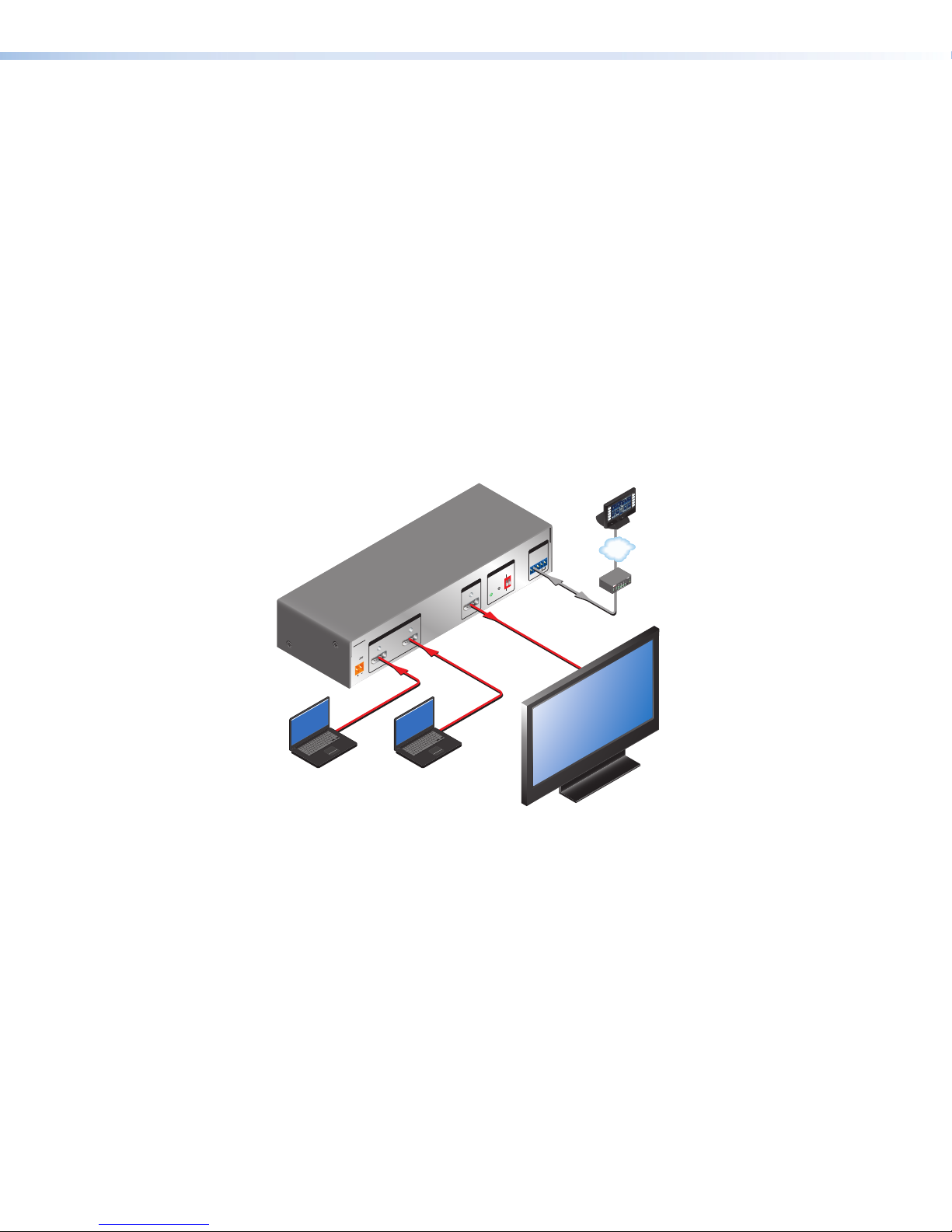
Application Diagram
The following diagram provides an example of how an SW2 DP switcher can be connected.
ron
ayPort Switcher
SW2 DP
Control
System
REMOTE
RS-232 AUTO
EDID
Rx GTx
DEFAULT
EDID
STORE
OUTPUT
STORED
INPUTS
21
POWER
12V
0.6A MAX
ON
OFF
DISPLAY
MUTE
SCREEN
UP
SCREEN
DOWN
TCP/IP
COM
TXRX
IPL 250
1
2
R
3
VCR
DVD
DOC
CAM
LAPTOP
PC
®
100
RELAY
LINK
ACT
3
INPUT
1
IR
31
4
31
2
42
42
Laptop with
DisplayPort Output
Laptop with
DisplayPort Output
Flat Panel Display
Figure 1. Connection Diagram for an SW2 DP DisplayPort Switcher
SW2 DP • Introduction 2
Page 11

Installation
This section gives an overview of the steps to install the SW2 DP switcher and detailed
instructions for cabling. It also provides a description of the rear panel connectors. The
following topics are covered:
• Installation Overview
• Rear Panel Features
• Wiring for RS-232 Control
• Connecting to the USB Port
• Enabling Auto-input Switching
• Wiring the DisplayPort Connectors
• Wiring the Power Connector (Optional)
Installation Overview
To install and set up the SW2 DP switcher:
1. Turn off all of the equipment and disconnect it from the power source.
2. (Optional) Mount the switcher on a rack shelf or furniture (see Mounting the SW2 DP
Switcher on page 28).
3. Connect DisplayPort input sources to one or both SW2 DP input connectors.
4. Connect a DisplayPort output device to the switcher output connector.
5. Connect your computer to one of the following control ports to configure and control
the switcher via SIS commands:
• RS-232 port — Pins 1, 2, and 3 of the Remote port for Serial RS-232 control (See
Wiring for RS-232 Control on page 5 for connection procedures.)
• Config port — USB mini-B connector for USB control (See Connecting to the
USB Port on page 6 for connection procedures.)
6. (Optional) To enable auto-input switching, use a jumper to short pins 4 and 5 of the
Remote connector together (see Enabling Auto-input Switching on page 8).
7. If necessary, wire a 2-pole captive screw connector to your external power supply (see
Wiring the Power Connector [Optional] on page 10).
8. Power on the output device.
9. Connect power to the switcher.
10. Power on the input devices.
SW2 DP • Installation 33
Page 12

Rear Panel Features
12
3
4
56
7
SW2 DP
POWER
12V
0.6A MAX
INPUTS OUTPUT EDID REMOTE
21
EDID
STORE
DEFAULT
STORED
RS-232 AUTO
Rx GTx
Figure 2. SW2 DisplayPort Rear Panel
Power connector — Plug the provided external 12 VDC power supply into this 2-pole,
1
3.5 mm captive screw connector.
ATTENTION:
• If not provided with a power supply, this product is intended to be supplied by a
power source marked “Class 2” or “LPS” and rated 12 VDC, minimum 1.0 A.
• Si le produit n’est pas fourni avec une source d’alimentation, il doit être
alimenté par une source d’alimentation de classe 2 ou LPS, avec une tension
nominale 12 Vcc, 1,0 A minimum.
Input connectors — Connect DisplayPort input devices to these female DisplayPort
2
connectors. Equalizers on the inputs compensate for a poor source signal and allow
cable runs of up to 25 feet (7.6 m). Mini DisplayPort devices are supported with
the appropriate adaptors and cables (not provided). See Wiring the DisplayPort
Connectors on page 9 for the connector pin assignments.
Output connector — Connect a DisplayPort output device to this female DisplayPort
3
connector. See Wiring the DisplayPort Connectors for the pin assignments.
EDID Store LED — This tri-colored LED lights to indicate EDID storing status:
4
• Red — EDID storing has been enabled (DIP switch 1 is set to Stored [down]) but
external EDID has not been stored and the factory default EDID is still present.
• Green — EDID storing has been enabled and the switcher is using external EDID.
• Amber — The EDID Store button has been pressed and the switcher is currently
storing EDID. (After the EDID is stored, the LED turns green.)
EDID Store button — Press this recessed button (using a pointed stylus or a small
5
screwdriver) to store the EDID of the connected display device (see Storing the
display EDID on page 15).
EDID DIP switch (switch 1, on the left) — Set this DIP switch to Stored (down) to
6
enable EDID storing. This is the default position (see Storing the display EDID).
Set the switch to Default (up) to use the SW DP2 default EDID of 1920x1080 @ 60 Hz
with 2-channel audio.
DIP switch 2 (on the right) is not used.
Remote connector — This 5-pole, 3.5 mm captive screw connector can be used for
7
RS-232 communication with the switcher and to enable auto-input switching.
• For RS-232 control, connect the Tx (transmit), Rx (receive) and G (ground) pins to
your computer serial port (see Wiring for RS-232 Control on the next page).
• To enable auto-input switching, short pins 4 and 5 of this connector together. In
auto-input switch mode, the switcher automatically switches to the active input (see
Enabling Auto-input Switching on page 8).
SW2 DP • Installation 4
Page 13

Wiring for RS-232 Control
The 5-pole, 3.5 mm captive screw Remote connector is used for RS-232 communication
and to enable auto-input switching between inputs connected to the switcher.
Use a female 9-pin D-to-bare wire RS-232 cable or a universal control cable to connect
your computer or control system to the Remote connector.
1. Wire the unterminated end of the RS-232 cable to the provided 5-pole captive screw
plug as described below. Connect the transmit, receive, and ground wires of the cable
to the first three pins on the connector, starting at the left:
• Connect the transmit wire to pin 1, which plugs into the Tx (transmit) port.
• Connect the receive wire to pin 2, which plugs into the Rx (receive) port.
• Connect the ground wire to pin 3, which plugs into the G (ground) port.
2. Plug the 5-pole connector into the Remote receptacle on the rear panel.
Figure 3 shows how to wire this shared connector for RS-232.
RS-232 Auto
Tx Rx
G
SW2 DP Switcher
Rear Panel
Remote Port
NOTE: If you use cable that has a drain
wire, tie the drain wire to ground
at both ends.
Ground (G)
Receive (Rx)
Transmit (Tx)
Transmit (Tx)
Receive (Rx)
9-pin HD
Connector
Computer or
Control System
RS-232 Port
Figure 3. Remote Connector Pin Assignments for RS-232
SW2 DP • Installation 5
Page 14

Connecting to the USB Port
SW2 DP Front Panel
The mini Type B USB port is located on the SW2 DP front panel. It can be used to configure
the switcher via SIS commands as an alternative to the RS-232 connector.
To set up a USB connection:
1. Connect a USB A to mini B cable between the USB Config port on the switcher front
panel and a USB port on your computer.
Mini Type B
USB
Type A
USB
USB 1
USB
Ports
USB Cable
AUTO
SWITCH
CONFIG
INPUTS
1 2
INPUTS OUTPUT
SIGNAL
12
HDCP
DISPLAYPORT SWITCHER
SW2 DP
Computer
Figure 4. USB Port Connection
2. If this is the first time you have connected an SW2 DP to this USB port on your
computer, the Found New Hardware Wizard opens. On the first screen, specify whether
you want the computer to connect to Windows Update in order to search the web for
the driver that it needs to communicate with the switcher via the USB port. This is not
necessary if the USB driver already exists on your computer.
• Select the Yes, this time only radio button if you want your computer to
connect to Windows Update only this one time.
• Select Yes, now and every time I connect a device if you want the computer
to automatically connect to Windows Update to search the web every time the
switcher is connected to this USB port.
• Select No, not this time if you do not want the computer to connect to Windows
Update to search the web at this time (for example, if the driver is already on your
computer).
See figure 5 on the next page.
SW2 DP • Installation 6
Page 15

Figure 5. Found New Hardware Wizard Opening Screen
3. Click Next. On the next screen, select the Install the software automatically
(Recommended) radio button, then click Next (you do not need to insert a disc).
Figure 6. Selecting the Radio Button to Install the USB Driver Automatically
Your computer locates the driver needed for it to communicate with the SW2 DP via the
USB port and loads it to its hard drive.
4. When the Completed screen appears, click Finish to close the wizard.
NOTE: This wizard appears only the first time you connect the SW2 DP to each
USB port. You do not see the wizard again unless you connect the switcher to a
different USB port on your computer.
5. Configure the switcher as desired using SIS commands (see the Remote
Configuration and Control section, beginning on page 17, for information on available
commands).
SW2 DP • Installation 7
Page 16

Enabling Auto-input Switching
You can set up the SW2 DP to automatically select the active connected input based on
the active Main Link signal. If both inputs are active, input 1 is selected. When auto-input
switching is in effect, the green Auto Switch LED on the front panel lights and the front panel
input selection buttons are disabled.
To enable auto-input switching:
1. Insert the provided 5-pole captive screw plug into the Remote connector on the
switcher rear panel.
2. Cut a small piece of wire to use as a jumper.
3. Insert the ends of the wire into slots 4 and 5 of the captive screw plug, shorting pins 4
and 5 together.
OUTPUT
EDID
EDID
STORE
DEFAULT
STORED
REMOTE
RS-232 AUTO
RX GTX
Figure 7. Remote Connector with Jumper
4. Use a small screwdriver to tighten the two screws above pin slots 4 and 5 of the plug,
so that the jumper wire ends remain securely in place.
Auto-input switching remains in effect as long as the jumper wire connects the two pins and
the 5-pole captive screw plug is attached to the Remote connector.
SW2 DP • Installation 8
Page 17

Wiring the DisplayPort Connectors
119
The DisplayPort connectors support data rates of either 1.62 Gbps (reduced bit rate) or
2.7Gbps (high bit rate), using either one, two, or four lanes. The SW2 DP supports mini
DisplayPort through the use of the appropriate adapters and cables (not provided). The
SW2 DP supports resolutions up to 2560x1600. If audio is available from the sources, it is
also available to the output device.
The figure on the right and the following table show pin assignments
for the DisplayPort connectors.
Pin Function Notes
1 ML Lane 0 (p) Main link lane 0 (positive)
2 GND Ground
Female DisplayPort
Connector
220
3 ML_Lane 0 (n) Main link lane 0 (negative)
4 ML_Lane 1 (p) Main link lane 1 (positive)
5 GND Ground
6 ML_Lane 1 (n) Main link lane 1 (negative)
7 ML_Lane 2 (p) Main link lane 2 (positive)
8 GND Ground
9 ML_Lane 2 (n) Main link lane 2 (negative)
10 ML_Lane 3 (p) Main link lane 3 (positive)
11 GND Ground
12 ML_Lane 3 (n) Main link lane 3 (negative)
13 CONFIG1 Connected to Ground 1
14 CONFIG2 Connected to Ground 1
15 AUX CH (p) Auxiliary Channel (positive)
16 GND Ground
17 AUX CH (n) Auxiliary Channel (negative)
18 Hot Plug Hot Plug Detect
19 Return Return for Power
20 DP_PWR Power for connector (3.3 V 500 mA)
SW2 DP • Installation 9
Page 18

Wiring the Power Connector (Optional)
A 12 VDC, 1 A desktop power supply with a 2-pole captive screw connector attached is
provided with the SW2 DP. Should it become necessary to attach a 2-pole captive screw
connector to your Extron power supply, follow these instructions:
WARNING:
• Risk of electric shock. Keep the two power cord wires separate while the power
supply is plugged in. Remove power before wiring.
• Les deux cordons d’alimentation doivent rester séparés tant que l’alimentation est
branchée. Coupez l’alimentation avant de faire les raccordements.
ATTENTION:
• Power supply voltage polarity is critical. Incorrect voltage polarity can damage the
equipment. Identify the negative (or ground) lead by the ridges on the side of the
cord.
• La polarité de la source d’alimentation est primordiale. Une polarité incorrecte
pourrait endommager la source d’alimentation et l’unité. Les stries sur le côté du
cordon permettent de repérer le pôle négatif du cordon d’alimentation.
• Always use a power supply supplied by or specified by Extron. Use of an
unauthorized power supply voids all regulatory compliance certification and may
cause damage to the supply and the end product.
• Utilisez toujours une source d’alimentation fournie ou recommandée par Extron.
L’utilisation d’une source d’alimentation non autorisée annule toute conformité
réglementaire et peut endommager la source d’alimentation ainsi que le produit
final.
• Unless otherwise stated, the AC to DC adapters are not suitable for use in air
handling spaces or in wall cavities. The power supply is to be located within the
same vicinity as the Extron AV processing equipment in an ordinary location,
Pollution Degree 2, secured to the equipment rack within the dedicated closet,
podium or desk.
• Sauf mention contraire, les adaptateurs CA/CC ne conviennent pas à une
utilisation dans les espaces d’aération ou dans les cavités murales. La source
d’alimentation doit être située à proximité de l’équipement audiovisuel Extron dans
un emplacement habituel, avec un degré de pollution 2, fixée à une estrade, un
bureau, ou dans une baie technique à l’intérieur d’un placard dédié.
• The installation must always be in accordance with the applicable provisions of
National Electrical Code ANSI/NFPA 70, article 75 and the Canadian Electrical Code
part 1, section 16. The power supply must not be permanently fixed to a building or
similar structure.
• Cette installation doit toujours être conforme aux dispositions applicables du Code
américain de l’électricité (National Electrical Code) ANSI/NFPA 70, article 725, et du
Code canadien de l’électricité, partie1, section16.
• If not provided with a power supply, this product is intended to be supplied by a
power source marked “Class 2” or “LPS” and rated 12 VDC, minimum 1.0 A.
• Si le produit n’est pas fourni avec une source d’alimentation, il doit être alimenté par
une source d’alimentation de classe 2 ou LPS, avec une tension nominale 12 Vcc,
0,5 A minimum.
SW2 DP • Installation 10
Page 19

To wire the power connector:
1. Cut the DC output cord to the length needed.
2. Strip the jacket to expose 3/16 inch (5 mm) of the conductors.
ATTENTION:
• The length of the exposed wires in the stripping process is important. The ideal
length is 3/16 inches (5 mm). If they are too long, the exposed wires may touch,
causing a short circuit between them. If they are too short, the wires can be
easily pulled out even if tightly fastened by the captive screws.
• La longueur des câbles exposés est importante lorsque l’on entreprend de les
dénuder. La longueur idéale est de 5mm (3/16inches). S’ils sont trop longs, les
câbles exposés pourraient se toucher et provoquer un court-circuit. S’ils sont
trop courts, ils peuvent être tirés facilement, même s’ils sont correctement serrés
par les borniers à vis.
3. Slide the leads into the supplied 2-pole captive screw plug and secure them, using a
small screwdriver.
ATTENTION:
• Do not tin the stripped power supply leads before attaching the captive screw
plug to them. Tinned wires are not as secure in the captive screw connectors
and can be easily pulled out. They may also break after being bent several
times.
• Ne pas étamer les conducteurs avant de les insérer dans le connecteur. Les
câbles étamés ne sont pas aussi bien fixés dans le connecteur et pourraient
être tirés. Ils peuvent aussi se casser après avoir été pliés plusieurs fois.
4. To verify the polarity of the power cord before connecting it, plug in the power supply
with no load and check the output with a voltmeter.
5. Use the supplied tie-wrap to strap the power cord to the extended tail of the connector.
Figure 8 shows how to wire the connector.
7/8”
Heat
Shrink
(22 mm)
3/16”
(5 mm) Max.
1/8”
(3 mm)
Tie Wrap
Captive Screw Connector
Figure 8. Power Connector Wiring
SW2 DP • Installation 11
Page 20

Operation
4
5
This section contains a description of the features available on the SW2 DP front panel and
provides procedures for operating the switcher.
• Front Panel Features
• Operations
Front Panel Features
1
AUTO
SWITCH
CONFIG
Figure 9. SW2 DP Front Panel
Auto Switch Active LED — This green LED lights when auto-input switching is in
1
effect (see Enabling Auto-input Switching on page 8 for the procedure to set up
auto-input switching).
Input selection buttons and LEDs — Press these buttons to select input 1 or
2
2. The LED at the right of each button lights when the SW2 DP has power and the
corresponding input is selected.
• The input buttons are disabled if auto-input switching is in effect; however, the LEDs
continue to light to indicate the selected input.
• The SW2 DP retains the previously selected input during a power cycle and the LED
for that input continues to light.
The input buttons are also used for enabling front panel lockout (executive mode) and
to initiate a system reset (see Enabling Front Panel Lockout (Executive Mode) and
Resetting, both on page 14).
Signal status LEDs —
3
• Inputs: Each input has a corresponding numbered Signal LED, which illuminates
when a source is connected to the input connector and Main Link activity is
detected from it.
2
INPUTS
1 2
3
INPUTS OUTPUT
SIGNAL
12
HDCP
SW2 DP
DISPLAYPORT SWITCHER
NOTE: If the source device connected to the selected input is HDCP encrypted
• Output: The Output Signal LED lights when the Main Link signal is being
transmitted to a connected output device.
(requires HDCP authentication), the corresponding signal LED may not light
unless HDCP has been authenticated.
SW2 DP • Operation 12
Page 21

Operations
HDCP status LEDs —
4
• Inputs: Each input has a numbered HDCP LED. If the connected source is HDCP
encrypted, the corresponding input LED lights.
• Output: The Output HDCP LED lights if the connected output device has been
authenticated.
NOTES:
• HDCP is re-authenticated on the output whenever a new input is selected.
• The LEDs do not light if the source does not require HDCP encryption or if
the display device connected to the output is not HDCP compliant.
Config port — Connect a USB cable (USB A to mini B) between your computer and
5
this female USB mini B port to configure and control the switcher via SIS commands
and to update the firmware.
Powering On the Switcher
Follow these steps to power on the SW2 DP:
1. Connect all input devices and the output to the switcher rear panel connectors (see
Rear Panel Features on page 4 for information on the rear panel connections).
2. Power on the output device.
3. Plug the power supply into the 2-pole captive screw power connector on the rear panel.
• The unit performs a self-test, during which the front panel Auto Switch and Input
LEDs each blink once in sequence from left to right. When the self-test completes,
the LED for the most recently selected input remains lit.
• Depending on the DIP switch setting, the switcher either reads the stored EDID
information or applies the default EDID.
4. Power on the input devices.
Selecting an Input
To switch an input to the output, press the desired input button on the front panel (ensure
that auto-input switching is not enabled). The LED corresponding to the selected input
button lights.
• To determine the current configuration, check the front panel input LEDs. The one that
is lit indicates the selected input. The LED remains lit until a new input is selected.
• Only one input can be switched to the output at a time.
You can also select an input using SIS commands (see the Input Selection commands
on page 19. Front panel input selection is disabled when auto-input switching is in effect.
SW2 DP • Operation 13 13
Page 22

Enabling Front Panel Lockout (Executive Mode)
1
2
Press and hold simultaneously
f
.
Front panel lock mode (executive mode) disables all front panel controls. Putting the
switcher in this mode enhances security by protecting against inappropriate or accidental
changes to settings. When the switcher is in lock mode, RS-232 and auto-input switching
remain available.
To lock or unlock the front panel, press and hold Input buttons 1 and 2 simultaneously for
3 seconds, then release them. The front panel LEDs blink three times, indicating that front
panel lock mode has been enabled or disabled (see the illustration below).
Resetting
Release buttons.
or 3 seconds.
LEDs blink 3 times
Figure 10. Enabling or Disabling Front Panel Lock Mode
You can also lock the front panel by using SIS commands (see the Front Panel Lockout
(Executive Mode) commands on page 19).
The following types of reset are available for the SW2 DP:
Factory settings
To reset the switcher to its original factory settings:
1. Disconnect power from the unit if it is connected.
2. Press and hold the Input 1 button while connecting power to the unit.
3. Continue holding the Input 1 button until the power-up sequence completes.
Retain current firmware
To reset the switcher to its default settings while retaining the currently installed firmware
version:
1. Press and hold the Input 1 button. The unit performs the power-up self-test, in which all
front panel LEDs blink once in succession.
2. When the self-test completes (after approximately 6 seconds all LEDs go dark except
the one for the most recently selected input), release the button.
You can also perform this reset by using an SIS command (see the Reset command on
page 20).
SW2 DP • Operation 14 14
Page 23

EDID Minder
The SW2 DP switchers utilize the EDID Minder, which maintains EDID communication to all
connected source devices, whether or not the source is selected. EDID information consists
of the display resolution, refresh rate, data rate, supported audio formats, and other
features. By factory default, the stored EDID contains information for a native resolution of
1920x1080 @ 60 Hz with 2-channel audio.
During power up, the source devices use an auxiliary channel to obtain Extended Display
Identification Data (EDID) from the display device. This allows the output signal to match the
resolution and refresh rate of the display device.
NOTES:
• The SW2 DP is fully HDCP compliant. The source negotiates with the SW2 DP
input and the display negotiates with the SW2 DP output.
• The SW2 DP does not support DisplayPort Content Protection (DPCP).
• The SW2 DP assigns identical EDIDs to the inputs.
EDID information is read from the display device connected to the output. The learned EDID
is stored in memory and is retained after a power cycle or after a new display device is
connected to the output. A reset to factory values returns the EDID to the default.
The new EDID is then available when DIP switch1 is in the Stored (down) position. Each
time a new EDID is recorded, it overwrites the existing data and is available when DIP switch
1 in the Stored position.
Storing the Display EDID
1. Connect the display device that will provide EDID information to the output.
2. Power on the display and the SW2 DP.
3. Set DIP switch 1 in the Stored (down) position (see EDID Minder DIP Switch settings
4. Using a stylus or small Philips screwdriver, press the recessed EDID Store button.
The EDID Minder LED lights amber, then changes to green when the recording process is
successfully completed.
Changing the stored EDID
To replace the stored EDID with that of a different display, connect the new display to
the output, then repeat steps 2 through 4 of the Storing the display EDID procedure
described above.
EDID Minder DIP switch settings
The EDID Minder DIP switch (DIP switch 1, on the left) selects the EDID value that is
presented to the source device:
• In the Default (up) position, the EDID value is the factory-stored default, with a
• In the Stored (down) position, the most recently recorded EDID value is used (this file
When the DIP switch is in this position, press the EDID button to initiate EDID storing.
for more information about setting the DIP switches).
resolution of 1920x1080 @ 60 Hz with 2-channel audio.
overwrites previously stored values). Before any other EDID file is recorded, this is also
the factory default resolution of 1920x1080 @ 60 Hz with 2-channel audio.
NOTE: DIP switch 2, on the right, is not used.
SW2 DP • Operation 15 15
Page 24

The table below summarizes the EDID Minder settings and functions.
DIP Switch 1 Position LED Color Function Indicated
Stored (down) Red EDID storing is enabled, but the default EDID is
still in effect.
Stored (down); EDID
Store button pressed
Amber EDID storing is enabled and the EDID of the
currently connected display is being recorded.
Stored (down) Green An EDID other than the default has been stored.
Default (up) Off The factory default EDID of 1920x1080 @ 60 Hz
with 2-channel audio is in effect.
SW2 DP • Operation 16 16
Page 25

Remote
Configuration and
Control
This section describes remote operation of the SW2 DP. Topics include:
• Using SIS Commands
• Updating Firmware Using Firmware Loader
Using SIS Commands
The SW2 DP can be remotely set up and controlled via a host computer or other device
(such as a control system) that is attached to the rear panel Remote port. Extron Simple
Instruction Set (SIS) commands are issued from the computer and transmitted to the
SW2 DP via RS-232 (see Wiring for RS-232 Control on page 5 or Connecting to the
USB Port on page 6 to connect to these ports).
Host-to-switcher Communications
SIS commands consist of one or more characters per field. No special characters are
required to begin or end a command sequence. Enter these commands on your computer
and send them to the SW2 DP using a communication software program such as Extron
DataViewer. When the switcher determines that a command is valid, it executes the
command and sends a response back to the host computer.
Most responses from the SW2 DP to the host computer end with a carriage return and a
line feed (CR/LF = ]), which signals the end of the response character string. A string is one
or more characters.
Switcher-initiated Messages
When a local event such as an input selection takes place, the switcher responds by
sending a message to the host, indicating what selection was entered. No response is
required from the host.
The following switcher-initiated message is sent when the switcher first powers up under
RS-232 control:
(C) Copyright 20nn, Extron Electronics DisplayPort Switcher, Vn.nn,
60-nnnn-nn
where 20nn is the year, Vn.nn is the firmware version number, and 60-nnnn-nn is the part
number of the unit.
NOTE: This copyright message is displayed only at switcher power-up and only under
RS-232 control.
SW2 DP • Remote Configuration and Control 1717
Page 26

Error Responses
If the switcher is unable to execute a command it receives because the command is invalid
or contains invalid parameters, the switcher returns an error response to the host. Error
response codes used by the SW2 DP are:
E01 – Invalid input channel number (out of range)
E06 – Invalid input selection during auto-input switching
E10 – Invalid command
E13 – Invalid value (out of range)
Using the Command and Response Table
The Command and Response Table for SIS Commands, starting on the next page, lists
valid ASCII and hexadecimal command codes, the switcher responses to the host, and a
description of the command function or the results of executing the command. The ASCII to
Hex Conversion Table below is for use with the command and response table.
ASCII to HEX Conversion Table
Space
.
Figure 11. ASCII to Hex Conversion Table
Symbol Definitions
]
= CR/LF (carriage return/line feed) (hex 0D 0A)
}
= Soft carriage return (no line feed)
•
= Space
E
= Escape key
X!
= Input number
0 through 2
0 = deselect all inputs
X@
= On and off, mute, or signal status
0 = Off, unmuted, or signal not present
1 = On, muted, or signal present
X#
= Current EDID
1 = default EDID: 1920x1080 @ 60 Hz with 2-channel audio
2 = native EDID on the output
X$
= Native resolution and refresh rate, translated from hexadecimal
X%
= Current EDID information in hex (256 bytes)
X^
= SW2 DP firmware version, expressed to the second decimal place
X&
= Unit name. Consists of a text string of up to 24 characters, which can be letters (a-z),
numerals (0-9), or hyphens (–). No blanks or space characters are permitted in the name. No
distinction is made between upper and lower case.
The first character must be a letter; the last character cannot be a hyphen.
NOTE: Unless otherwise indicated, commands are not case sensitive.
SW2 DP • Remote Configuration and Control 18 18 18
Page 27

Command and Response Table for SIS Commands
Command
Input Selection
Select an input (video and audio)
Video Mute
Video mute
View video mute status
Audio Mute
Audio mute
View audio mute status
Signal Status
Request all signal status
HDCP
HDCP Authorized device on
HDCP authorized device off
View HDCP authorization status
EDID Minder
View EDID native resolution
View EDID in Hex
Front Panel Lockout (Executive Mode)
Enable and disable lock mode
View lockout status
ASCII Command
(Host to Unit)
X!
!
X@
B
B
X@
Z
Z
E
}
LS
E
E 1 HDCP
E
E 0 HDCP
E
E HDCP
E
N * EDID
E
R * EDID
X@
X
X
}
}
} X@ ]
} X$ ]
} X% ]
Response
(Unit to Host)
In X! * All
Vmt X@
]
]
X@ ]
Amt X@
]
X@ ]
Sig X@ * X@ * X@
hdcp E 1
hdcp E 0
Exe X@
]
]
]
X@ ]
]
Additional Description
Select audio (if available) and video
input X!.
X!
= input number: 0 through 2.
0 = deselect (mute) all inputs.
Mute or unmute the video signal. For
X@
:
= mute
1
0 = unmute
Show video mute status X@.
Mute the audio signal. For X@:
= mute
1
0 = unmute
Show audio mute status X@.
Show the presence or absence of a
signal at each input and the output in
the following format:
Input1 [Input2]*Output
Inputs are shown in numerical order.
X@
= signal status. For X@:
= signal present
1
0 = signal not present
HDCP authorized device on
HDCP authorized device off
Show the HDCP device status.
Show the native resolution X$ of the
current EDID.
Example: 1020x1080 @ 60 Hz
View the current EDID information
in hexadecimal (256 bytes).
For X@:
= lock front panel
1
0 = unlock front panel (default)
Show lock mode on/off status.
X%
SW2 DP • Remote Configuration and Control 19 19 19
Page 28

Command
ASCII Command
(Host to Unit)
Response
(Unit to Host)
Additional Description
Unit Name
Set unit name
E X&
CN
}
Ipn • X&
]
Set name X& for the SW2 DP unit.
X&
= Text string of up to 24
characters:
• Letters (a-z), numerals (0-9), and
hyphens (–) are permitted.
• Blanks or space characters are not
permitted.
• No distinction is made between
upper and lower case.
• The first character must be a letter;
the last character cannot be a
hyphen.
View unit name E
} X& ]
CN
Show assigned unit name X&.
Information Requests
Request part number
Query firmware version
Example:
Query auto-input switching status
N
Q
Q
72 #
60-1210-01
X^ ]
]
1.01
Asw X@
]
]
Show the switcher part number.
Show firmware build number X^,
expressed to the second decimal
place.
Show On and Off status of auto-input
switching. For X@:
0 = disabled
= enabled
1
Reset
Reset
Upload Firmware
Upload firmware
E
ZXXX
E
Upload
}
}
]
Zpx
...go
]
Upl
Reset the switcher to default values,
retaining the current version of
firmware. EDID is reset to 1920x1080
@ 60 Hz.
Upload a new firmware version from
the computer. Upl appears after the
upload is complete.
SW2 DP • Remote Configuration and Control 20 20 20
Page 29

Updating Firmware Using Firmware Loader
Updates to the SW2 DP firmware are made available periodically via the Extron website. You
can find out what version of firmware is currently loaded on your switcher by entering the
SIS Q command via the RS-232 interface (see Using SIS Commands on page 17 for the
procedure for entering SIS commands).
Downloading and Installing Firmware Loader
Extron recommends using the Firmware Loader software to update the firmware on the
SW2 DP. If you do not already have Firmware Loader installed on your computer, download
it as follows:
1. Visit the Extron website at www.extron.com and click the Download tab.
2. On the Download Center screen, click the Software link on the left sidebar menu.
3. On the next Download Center screen, locate Firmware Loader and click its Download
link.
Figure 12. Download Links for Firmware Loader
4. On the next screen, enter the requested information, then click the
Download fw_loader_vnxnxn.exe button (where n is the Firmware Loader version
number).
5. Follow the instructions on the rest of the download screens to save the executable
Firmware Loader installer file to your computer. Note the folder to which the file was
saved.
6. In Windows Explorer or another file browser, locate the downloaded executable installer
file, and double-click it to open it.
7. Follow the instructions on the Installation Wizard screens to install Firmware Loader on
your computer. Unless you specify otherwise, the installer program places the Firmware
Loader file, FWLoader.exe, at c:\Program Files\Extron\FWLoader (Windows XP) or
c:\Program Files (86x)\Extron\FWLoader (for Windows 7).
SW2 DP • Remote Configuration and Control 21 21 21
Page 30

Downloading the SW2 DP Firmware
To obtain the latest version of firmware for your SW2 DP:
1. Visit the Extron website (www.extron.com), click the Download link at the top, then
click the Firmware link on the left sidebar menu.
Figure 13. Firmware Link on the Download Screen
2. On the next Download Center screen, click the Download link for the SW2 DP firmware.
3. On the next screen that appears, enter the requested user information, then click the
Download button.
4. Follow the instructions on the rest of the download screens to save the executable
firmware file to your computer. Note the folder to which the file was saved.
5. In Windows Explorer or another file browser, locate the downloaded executable file and
double-click it to open it.
6. Follow the instructions on the Installation Wizard screens to install the new firmware
on your computer. A Release Notes file, giving information on what has changed in
the new firmware version, and a set of instructions for updating the firmware are also
downloaded.
Loading the Firmware to the Switcher
To load a new version of firmware to the switcher using Firmware Loader, connect the first
three pins (labeled “RS-232”) of the switcher Remote port to your computer serial port (see
Wiring for RS-232 Control on page 5) or connect the front panel Config port to a USB
port on your computer (see Connecting to the USB Port on page 6).
1. If you have not already done so, download and install the Firmware Loader executable
installer file to your computer (see Downloading and Installing Firmware Loader on
the previous page).
2. If necessary, download the latest SW2 DP firmware version and install it on your
computer (see Downloading the SW2 DP Firmware).
3. Open the Firmware Loader via your desktop Start menu by selecting the following:
Start > All Programs > Extron Electronics > Firmware Loader > Firmware
Loader
4. The Firmware Loader window opens with the Add Device window displayed in front.
5. On the Add Device window, select SW2 DP from the Device Names drop-down menu.
SW2 DP • Remote Configuration and Control 22 22 22
Page 31

6. From the Connection Method drop-down menu, select RS-232 or USB.
Figure 14. Connection Method Menu on the Add Device Window
7. Depending on the connection method that you selected, additional options appear.
Make the appropriate selections for your connection method.
• RS-232: Select the appropriate options from the Com Port and Baud Rate menus
(this information is provided by your system administrator).
Figure 15. RS-232 Drop-down Menus on Add Device Window
• USB: Only the Extron USB Device_0 option is available on the Available
Devices menu. Make sure that it is selected.
8. Click Connect. If the connection is successful, SW2 DP appears in green in the
Connected Device section, followed by a green check mark (see figure 17 on
page 25).
SW2 DP • Remote Configuration and Control 23 23 23
Page 32

9. Click the Browse button in the New Firmware File (Optional) panel.
10. On the Open window, navigate to the new firmware file, which has an S19 extension,
and double-click it.
Figure 16. Open Window for Firmware File Selection
ATTENTION:
• Valid firmware files must have the file extension S19. A file with any other
extension is not a firmware upgrade for this product and could cause the unit
to stop functioning.
• Les fichiers firmware valides doivent contenir l’extension fichier S19. Un fichier
avec n’importe quelle autre extension n’est pas une mise à jour de firmware
pour cet appareil et l’appareil pourrait arrêter de fonctionner.
SW2 DP • Remote Configuration and Control 24 24 24
Page 33

NOTES:
• The original factory-installed firmware is permanently available on the SW2 DP.
If the attempted firmware upload fails for any reason, the switcher reverts to the
factory version.
• When downloaded from the Extron website, by default the firmware is placed in
a folder at:
C:\Program Files\Extron\Firmware\SW2 DP (Windows XP) or
C:\Program Files (x86)\Extron\Firmware\SW2 DP (Windows 7).
On the Add Device window, the path to the new firmware file is displayed in the Path
field.
Figure 17. Path to the New Firmware File
SW2 DP • Remote Configuration and Control 25 25 25
Page 34

11. If this is the only device to which you are uploading firmware, click Add. The
switcher information is added to the Devices panel of the Firmware Loader window
and the Add Device window closes.
12. If you will be uploading the firmware to multiple SW2 DP switchers that are
connected to your computer, do the following:
a. Click Add Next. Your first device is added to the Devices panel of the Firmware
Loader window, and the Add Device window remains open.
b. For each additional device you want to add to the Firmware Loader window,
repeat steps 5 through 9, beginning on page 22, then click Add Next.
c. For the last device, click Add (instead of Add Next) to add the device and to close
the Add Device window.
Figure 18. Firmware Loader Screen with an SW2 DP Added
13. If you want to remove a device from the Devices section, do the following:
a. Click on the names of the devices to be deleted, to highlight them.
b. From the Edit menu, select Remove Selected Devices.
c. On the Remove Devices window, select or deselect any devices on the list as
desired, then click Remove.
To remove all devices from the field, select Remove All Devices from the Edit menu.
14. Click Begin. The following indicators on the Firmware Loader window show the
progress of the update (see figure 19 on the next page):
• The Transfer Time panel shows the remaining and elapsed time for the update.
• The Total Progress panel displays a progress bar with Uploading... above it.
• In the Devices panel, the Progress column displays an incrementing percentage
and another progress bar. The Status column displays Uploading.
SW2 DP • Remote Configuration and Control 26 26 26
Page 35

Figure 19. Firmware Upload in Progress
15. The upload is complete when the Remaining Time panel shows 00.00.00, the
Progress column shows 100%, and Completed is displayed above the progress bar and
in the Status field. Close the Firmware Loader window.
Figure 20. Firmware Upload Complete
SW2 DP • Remote Configuration and Control 27 27 27
Page 36

Reference
Information
Mounting the SW2 DP Switcher
The SW2 DP switcher can be set on a table, mounted on a rack shelf, or mounted under a
desk, podium, or table.
Tabletop Use
Four self-adhesive rubber feet are included with the SW2 DP. For tabletop use, attach one
foot at each corner on the bottom of the unit, and place the switcher where desired.
Rack Mounting
UL rack mounting guidelines
The following Underwriters Laboratories (UL) guidelines pertain to the safe installation of the
equipment in a rack.
1. Elevated operating ambient temperature — If the equipment is installed in a closed
or multi-unit rack assembly, the operating ambient temperature of the rack environment
may be greater than room ambient temperature. Therefore, install the equipment in
an environment compatible with the maximum ambient temperature (Tma = +122 °F,
+50 °C) specified by Extron.
2. Reduced air flow — Install the equipment in a rack so that the amount of air flow
required for safe operation of the equipment is not compromised.
3. Mechanical loading — When mounting the equipment in the rack, ensure that uneven
mechanical loading does not cause a hazardous condition.
4. Circuit overloading — When connecting the equipment to the supply circuit, consider
the effect that circuit overloading might have on overcurrent protection and supply
wiring. Consider equipment nameplate ratings when addressing this concern.
5. Reliable earthing (grounding) — Maintain reliable grounding of rack-mounted
equipment. Pay particular attention to supply connections other than direct connections
to the branch circuit (for example, use of power strips).
Mounting on a rack shelf
You can mount the SW2 DP to a rack shelf that is at least 3 inches deep.
1. If feet were previously attached to the bottom of the unit, remove them.
2. Mount the switcher on the rack shelf, using two 4-40 x 3/16 inch screws in opposite
(diagonal) corners to secure the unit to the shelf (see figure 21).
3. Install blank panels or other units on the rack shelf as desired.
SW2 DP • Reference Information 282828
Page 37

4. Install the shelf in the rack.
HalfRack6inchRackShelf
6" Deep Rack Shelf
Front false
faceplate
uses 2
screws.
Use 2 mounting holes on
opposite corners.
1/2 Rack Width Front False
Faceplate
(2) 4-40 x 3/16"
Screws
Figure 21. Mounting an SW2 DP Switcher on a Standard 9.5-inches Deep
Rack Shelf
Back of the rack mounting
The SW2 DP can also be mounted vertically to the front or rear rack supports, using the
optional MBB 100 Back of the Rack Mounting Kit as follows:
1. If rubber feet were previously attached to the bottom of the unit, remove them.
2. Remove the two screws from each side of the switcher. Retain the screws for possible
later reassembly.
3. Attach the brackets to the sides of the unit, using the longer screws included in the
mounting kit.
Figure 22. Attaching the Back of the Rack Mounting Brackets
SW2 DP • Reference Information 29 29 29 29
Page 38

4. Mount the switcher to the rack support, using the two included rack screws.
IR
1
Figure 23. Mounting an SW2 DP to a Back of the Rack Support
Furniture Mounting
2
3
INPUTS
4
5
6
7
8
1
2
3
OUTPUTS
4
5
6
7
8
ENTER
PRESET
MAV SERIES
AV MATRIX SWITCHER
I/O
VID
AUD
+dB
-dB
AUDIO SETUP
To mount an SW2 DP switcher under a desk, table, or podium, use the optional MBU 123
Mini Under-Desk Mounting Kit as follows:
1. If rubber feet were previously attached to the bottom of the unit, remove them.
2. Remove the two screws from each side of the switcher. Retain the screws for possible
reassembly later.
3. Attach the brackets to the sides of the unit, using the provided machine screws.
Figure 24. Preparing the SW2 DP Switcher for Under-furniture Mounting
4. Hold the unit with the attached brackets against the underside of the table or other
furniture. On the mounting surface, mark the location of the screw holes for each
bracket.
SW2 DP • Reference Information 30 30 30 30
Page 39

5. Drill 3/32 inch (2 mm) diameter pilot holes, 1/4 inch (6.3 mm) deep, into the mounting
surface at the marked screw locations.
6. Insert #8 wood screws into the four pilot holes. Tighten each screw into the mounting
surface until slightly less than 1/4 inch of the screw head protrudes.
7. Align the centers of the slots in the brackets with the mounting screws and place the
unit against the surface, with the screw heads through the bracket slots.
8. Slide the unit slightly forward or back, then tighten all four screws to secure it in place.
SW2 DP • Reference Information 31 31 31 31
Page 40

Extron Warranty
Extron Electronics warrants this product against defects in materials and workmanship for a period of three years
from the date of purchase. In the event of malfunction during the warranty period attributable directly to faulty
workmanship and/or materials, Extron Electronics will, at its option, repair or replace said products or components,
to whatever extent it shall deem necessary to restore said product to proper operating condition, provided that it is
returned within the warranty period, with proof of purchase and description of malfunction to:
USA, Canada, South America,
and Central America:
Extron Electronics
1230 South Lewis Street
Anaheim, CA 92805
U.S.A.
Europe and Africa:
Extron Europe
Hanzeboulevard 10
3825 PH Amersfoort
The Netherlands
Japan:
Extron Electronics, Japan
Kyodo Building, 16 Ichibancho
Chiyoda-ku, Tokyo 102-0082
Japan
China:
Extron China
686 Ronghua Road
Songjiang District
Shanghai 201611
China
Asia:
Extron Asia Pte Ltd
135 Joo Seng Road, #04-01
PM Industrial Bldg.
Singapore 368363
Middle East:
Extron Middle East
Dubai Airport Free Zone
F13, PO Box 293666
United Arab Emirates, Dubai
Singapore
This Limited Warranty does not apply if the fault has been caused by misuse, improper handling care, electrical
or mechanical abuse, abnormal operating conditions, or if modifications were made to the product that were not
authorized by Extron.
NOTE: If a product is defective, please call Extron and ask for an Application Engineer to receive an RA (Return
Authorization) number. This will begin the repair process.
USA: 714.491.1500 or 800.633.9876 Europe: 31.33.453.4040
Asia: 65.6383.4400 Japan: 81.3.3511.7655
Units must be returned insured, with shipping charges prepaid. If not insured, you assume the risk of loss or damage
during shipment. Returned units must include the serial number and a description of the problem, as well as the
name of the person to contact in case there are any questions.
Extron Electronics makes no further warranties either expressed or implied with respect to the product and its quality,
performance, merchantability, or fitness for any particular use. In no event will Extron Electronics be liable for direct,
indirect, or consequential damages resulting from any defect in this product even if Extron Electronics has been
advised of such damage.
Please note that laws vary from state to state and country to country, and that some provisions of this warranty may
not apply to you.
Contact Information
Extron Headquarters
+1.800.633.9876 (Inside USA/Canada Only)
Extron USA - West Extron USA - East
+1.714.491.1500 +1.919.850.1000
+1.714.491.1517 FAX +1.919.850.1001 FAX
Extron Europe
+800.3987.6673
(Inside Europe Only)
+31.33.453.4040
+31.33.453.4050 FAX
© 2017 Extron Electronics All rights reserved. www.extron.com
Extron Asia
+65.6383.4400
+65.6383.4664 FAX
Extron Japan
+81.3.3511.7655
+81.3.3511.7656 FAX
Extron China
+86.21.3760.1568
+86.21.3760.1566 FAX
Extron Middle East
+971.4.299.1800
+971.4.299.1880 FAX
Extron Australia
+61.8.8113.6800
+61.8.8351.2511 FAX
Extron India
1800.3070.3777
(Inside India Only)
+91.80.3055.3777
+91.80.3055.3737 FAX
 Loading...