

Page 1

SMX System
MultiMatrix Switcher
Setup Guide
Matrix Switcher
68-1452-50 Rev. B
10 11
Page 2

Safety Instructions • English
This symbol is intended to alert the user of important operating
and maintenance (servicing) instructions in the literature
provided with the equipment.
This symbol is intended to alert the user of the presence of
uninsulated dangerous voltage within the product’s enclosure
that may present a risk of electric shock.
Caution
Read Instructions • Read and understand all safety and operating
instructions before using the equipment.
Retain Instructions • The safety instructions should be kept for future
reference.
Follow Warnings • Follow all warnings and instructions marked on the
equipment or in the user information.
Avoid Attachments • Do not use tools or attachments that are not
recommended by the equipment manufacturer because they may be
hazardous.
Warning
Power sources • This equipment should be operated only from the power source
indicated on the product. This equipment is intended to be used with a main power
system with a grounded (neutral) conductor. The third (grounding) pin is a safety
feature, do not attempt to bypass or disable it.
Power disconnection • To remove power from the equipment safely, remove all power
cords from the rear of the equipment, or the desktop power module (if detachable),
or from the power source receptacle (wall plug).
Power cord protection • Power cords should be routed so that they are not likely to be
stepped on or pinched by items placed upon or against them.
Servicing • Refer all servicing to qualified service personnel. There are no user-
serviceable parts inside. To prevent the risk of shock, do not attempt to service
this equipment yourself because opening or removing covers may expose you to
dangerous voltage or other hazards.
Slots and openings • If the equipment has slots or holes in the enclosure, these are
provided to prevent overheating of sensitive components inside. These openings
must never be blocked by other objects.
Lithium battery • There is a danger of explosion if battery is incorrectly
replaced. Replace it only with the same or equivalent type recommended by
the manufacturer. Dispose of used batteries according to the manufacturer’s
instructions.
Consignes de Sécurité • Français
Ce symbole sert à avertir l’utilisateur que la documentation
fournie avec le matériel contient des instructions importantes
concernant l’exploitation et la maintenance (réparation).
Ce symbole sert à avertir l’utilisateur de la présence dans le
boîtier de l’appareil de tensions dangereuses non isolées
posant des risques d’électrocution.
Attention
Lire les instructions• Prendre connaissance de toutes les consignes de
sécurité et d’exploitation avant d’utiliser le matériel.
Conserver les instructions• Ranger les consignes de sécurité afin de pouvoir
les consulter à l’avenir.
Respecter les avertissements • Observer tous les avertissements et consignes
marqués sur le matériel ou présentés dans la documentation utilisateur.
Eviter les pièces de xation • Ne pas utiliser de pièces de fixation ni d’outils
non recommandés par le fabricant du matériel car cela risquerait de poser
certains dangers.
Sicherheitsanleitungen • Deutsch
Dieses Symbol soll dem Benutzer in der im Lieferumfang
enthaltenen Dokumentation besonders wichtige Hinweise zur
Bedienung und Wartung (Instandhaltung) geben.
Dieses Symbol soll den Benutzer darauf aufmerksam machen,
daß im Inneren des Gehäuses dieses Produktes gefährliche
Spannungen, die nicht isoliert sind und die einen elektrischen
Schock verursachen können, herrschen.
Achtung
Lesen der Anleitungen • Bevor Sie das Gerät zum ersten Mal verwenden,
sollten Sie alle Sicherheits-und Bedienungsanleitungen genau durchlesen
und verstehen.
Aufbewahren der Anleitungen • Die Hinweise zur elektrischen Sicherheit
des Produktes sollten Sie aufbewahren, damit Sie im Bedarfsfall darauf
zurückgreifen können.
Befolgen der Warnhinweise • Befolgen Sie alle Warnhinweise und
Anleitungen auf dem Gerät oder in der Benutzerdokumentation.
Keine Zusatzgeräte • Verwenden Sie keine Werkzeuge oder Zusatzgeräte,
die nicht ausdrücklich vom Hersteller empfohlen wurden, da diese eine
Gefahrenquelle darstellen können.
Instrucciones de seguridad • Español
Este símbolo se utiliza para advertir al usuario sobre
instrucciones importantes de operación y mantenimiento (o
cambio de partes) que se desean destacar en el contenido de
la documentación suministrada con los equipos.
Este símbolo se utiliza para advertir al usuario sobre la presencia
de elementos con voltaje peligroso sin protección aislante,
que puedan encontrarse dentro de la caja o alojamiento del
producto, y que puedan representar riesgo de electrocución.
Precaucion
Leer las instrucciones • Leer y analizar todas las instrucciones de operación y
seguridad, antes de usar el equipo.
Conservar las instrucciones • Conservar las instrucciones de seguridad para
futura consulta.
Obedecer las advertencias • Todas las advertencias e instrucciones marcadas
en el equipo o en la documentación del usuario, deben ser obedecidas.
Evitar el uso de accesorios • No usar herramientas o accesorios que no
sean especificamente recomendados por el fabricante, ya que podrian
implicar riesgos.
Avertissement
Alimentations• Ne faire fonctionner ce matériel qu’avec la source d’alimentation
indiquée sur l’appareil. Ce matériel doit être utilisé avec une alimentation principale
comportant un fil de terre (neutre). Le troisième contact (de mise à la terre) constitue
un dispositif de sécurité : n’essayez pas de la contourner ni de la désactiver.
Déconnexion de l’alimentation• Pour mettre le matériel hors tension sans danger,
déconnectez tous les cordons d’alimentation de l’arrière de l’appareil ou du module
d’alimentation de bureau (s’il est amovible) ou encore de la prise secteur.
Protection du cordon d’alimentation • Acheminer les cordons d’alimentation de
manière à ce que personne ne risque de marcher dessus et à ce qu’ils ne soient pas
écrasés ou pincés par des objets.
Réparation-maintenance • Faire exécuter toutes les interventions de réparation-
maintenance par un technicien qualifié. Aucun des éléments internes ne peut être
réparé par l’utilisateur. Afin d’éviter tout danger d’électrocution, l’utilisateur ne doit
pas essayer de procéder lui-même à ces opérations car l’ouverture ou le retrait des
couvercles risquent de l’exposer à de hautes tensions et autres dangers.
Fentes et orices • Si le boîtier de l’appareil comporte des fentes ou des orifices, ceux-ci
servent à empêcher les composants internes sensibles de surchauffer. Ces ouvertures
ne doivent jamais être bloquées par des objets.
Lithium Batterie • Il a danger d’explosion s’ll y a remplacment incorrect de la batterie.
Remplacer uniquement avec une batterie du meme type ou d’un ype equivalent
recommande par le constructeur. Mettre au reut les batteries usagees conformement
aux instructions du fabricant.
Vorsicht
Stromquellen • Dieses Gerät sollte nur über die auf dem Produkt angegebene
Stromquelle betrieben werden. Dieses Gerät wurde für eine Verwendung mit einer
Hauptstromleitung mit einem geerdeten (neutralen) Leiter konzipiert. Der dritte
Kontakt ist für einen Erdanschluß, und stellt eine Sicherheitsfunktion dar. Diese
sollte nicht umgangen oder außer Betrieb gesetzt werden.
Stromunterbrechung • Um das Gerät auf sichere Weise vom Netz zu trennen, sollten
Sie alle Netzkabel aus der Rückseite des Gerätes, aus der externen Stomversorgung
(falls dies möglich ist) oder aus der Wandsteckdose ziehen.
Schutz des Netzkabels • Netzkabel sollten stets so verlegt werden, daß sie nicht im
Weg liegen und niemand darauf treten kann oder Objekte darauf- oder unmittelbar
dagegengestellt werden können.
Wartung • Alle Wartungsmaßnahmen sollten nur von qualiziertem Servicepersonal
durchgeführt werden. Die internen Komponenten des Gerätes sind wartungsfrei.
Zur Vermeidung eines elektrischen Schocks versuchen Sie in keinem Fall, dieses
Gerät selbst öffnen, da beim Entfernen der Abdeckungen die Gefahr eines
elektrischen Schlags und/oder andere Gefahren bestehen.
Schlitze und Öffnungen • Wenn das Gerät Schlitze oder Löcher im Gehäuse aufweist,
dienen diese zur Vermeidung einer Überhitzung der empndlichen Teile im
Inneren. Diese Öffnungen dürfen niemals von anderen Objekten blockiert werden.
Litium-Batterie • Explosionsgefahr, falls die Batterie nicht richtig ersetzt
wird. Ersetzen Sie verbrauchte Batterien nur durch den gleichen oder einen
vergleichbaren Batterietyp, der auch vom Hersteller empfohlen wird. Entsorgen Sie
verbrauchte Batterien bitte gemäß den Herstelleranweisungen.
Advertencia
Alimentación eléctrica • Este equipo debe conectarse únicamente a la fuente/tipo
de alimentación eléctrica indicada en el mismo. La alimentación eléctrica de este
equipo debe provenir de un sistema de distribución general con conductor neutro
a tierra. La tercera pata (puesta a tierra) es una medida de seguridad, no puentearia
ni eliminaria.
Desconexión de alimentación eléctrica • Para desconectar con seguridad la acometida
de alimentación eléctrica al equipo, desenchufar todos los cables de alimentación
en el panel trasero del equipo, o desenchufar el módulo de alimentación (si fuera
independiente), o desenchufar el cable del receptáculo de la pared.
Protección del cables de alimentación • Los cables de alimentación eléctrica se deben
instalar en lugares donde no sean pisados ni apretados por objetos que se puedan
apoyar sobre ellos.
Reparaciones/mantenimiento • Solicitar siempre los servicios técnicos de personal
calificado. En el interior no hay partes a las que el usuario deba acceder. Para evitar
riesgo de electrocución, no intentar personalmente la reparación/mantenimiento
de este equipo, ya que al abrir o extraer las tapas puede quedar expuesto a voltajes
peligrosos u otros riesgos.
Ranuras y aberturas • Si el equipo posee ranuras o orificios en su caja/alojamiento,
es para evitar el sobrecalientamiento de componentes internos sensibles. Estas
aberturas nunca se deben obstruir con otros objetos.
Batería de litio • Existe riesgo de explosión si esta batería se coloca en la posición
incorrecta. Cambiar esta batería únicamente con el mismo tipo (o su equivalente)
recomendado por el fabricante. Desachar las baterías usadas siguiendo las
instrucciones del fabricante.
Page 3

FCC Class A Notice
This equipment has been tested and found to comply with the limits for a Class A
digital device, pursuant to part 15 of the FCC Rules. Operation is subject to the
following two conditions:
1. This device may not cause harmful interference.
2. This device must accept any interference received, including interference
that may cause undesired operation.
The Class A limits are designed to provide reasonable protection against harmful
interference when the equipment is operated in a commercial environment. This
equipment generates, uses, and can radiate radio frequency energy and, if not
installed and used in accordance with the instruction manual, may cause harmful
interference to radio communications. Operation of this equipment in a residential
area is likely to cause harmful interference, in which case the user will be required
to correct the interference at his own expense.
NOTE: This unit was tested with shielded cables on the peripheral devices.
Shielded cables must be used with the unit to ensure compliance with
FCC emissions limits.
For more information on safety guidelines, regulatory compliances, EMI/
EMF compliance, accessibility, and related topics, click here.
Page 4

Conventions Used in this Guide
In this user guide, the following are used:
NOTE: A note draws attention to important information.
TIP: A tip provides a suggestion to make working with the ap-
plication easier.
CAUTION: A caution indicates a potential hazard to equipment
WARNING: A warning warns of things or actions that might
Commands are written in the fonts shown here:
or data.
cause injury, death, or other severe consequences.
^AR Merge Scene,,Op1 scene 1,1 ^B 51 ^W^C
[01] R 0004 00300 00400 00800 00600 [02] 35 [17] [03]
E X! *X1&* X2)* X2#* X2!
NOTE: For commands and examples of computer or device
responses mentioned in this guide, the character “0”
is used for the number zero and “O” represents the
capital letter “o.”
Computer responses and directory paths that do not have variables
are written in the font shown here:
CE
}
Reply from 208.132.180.48: bytes=32 times=2ms
TTL=32
C:\Program Files\Extron
Variables are written in slanted form as shown here:
ping xxx.xxx.xxx.xxx —t
SOH R Data STX Command ETB ETX
Selectable items, such as menu names, menu options, buttons, tabs,
and field names are written in the font shown here:
From the File menu, select New.
Click the OK button.
Copyright
© 2011 Extron Electronics. All rights reserved.
Trademarks
All trademarks mentioned in this guide are the properties of their respective owners.
Page 5

Contents
Introduction .......................................1
About This Guide ...............................1
About the SMX System
MultiMatrix Switcher .......................1
Installation ........................................3
Rear Panel ..........................................3
Connecting Inputs .........................3
Connecting Outputs ......................3
Connecting Control Devices ..........3
Connecting Power .........................4
Setting Plane Addresses ................4
Installing Additional I/O Boards ....4
Wiring Audio Connectors ..................4
Front Panel Operation .....................6
Front Panel Overview ........................6
Creating Ties.......................................7
Viewing Ties .......................................8
Muting or Unmuting Outputs ...........8
Removing Ties ....................................9
Saving and Recalling I/O Presets .....10
Global Preset ................................10
Plane Preset ..................................11
Adjusting the Input Audio Level .....12
Adjusting the Output Audio
Volume ............................................14
Using Reset Levels ............................16
Reset Mode Uses ..........................16
Setting the Front Panel Locks
(Executive Modes) ..........................18
Selecting Lock Mode 2 ................18
Selecting Lock Mode 1 ................18
SIS Programming Guide ................19
SIS Overview .....................................19
Network (Ethernet)
Connections ................................19
Verbose Mode ..............................20
Host-to-switcher Instructions ......20
Error Messages .............................20
EDID ..............................................21
SIS Command Tables ........................22
Conguration and Control ...........32
Installing and Starting the SMX
Control Program .............................32
Installing the Program .................32
Starting the Program ...................33
Accessing the HTML Pages ..............34
Using the Web Pages .......................35
Status Page ...................................35
Configuration Page .....................36
File Management Page ...............36
Control Page ................................36
Reference Material .........................37
Ethernet Link ....................................37
Choosing a Network Cable .........37
Terminating the Network
Cable ...........................................37
Mounting the SMX ..........................38
Installing New Boards ......................38
SMX System MultiMatrix Switcher • Contents v
Page 6

vi SMX System MultiMatrix Switcher • Contents
Page 7

Introduction
This section gives an overview of SMX System MultiMatrix switchers
and includes:
• About This Guide
• About the SMX System MultiMatrix Switchers
About This Guide
This setup guide describes basic instructions for the set up,
configuration, and operation of the Extron SMX matrix switcher.
The SMX matrix switcher can be controlled through the front panel
controls, Simple Instruction Set (SIS™) commands, the SMX Control
Program which runs on computers using the Windows® operating
System, or built-in HTML pages.
NOTES: • The term "SMX" refers to a typical SMX System
See Front Panel Operation on page 6 for operating the SMX through
the front panel controls, SIS Programming Guide on page 19 for
selected SIS commands, Conguration and Control on page 32 for
installing the SMX Control Program, or Using the Web Pages to
congure the SMX on page 35 for accessing the built-in HTML pages.
MultiMatrix Switcher throughout this guide.
• For detailed information on the SMX, see to the User
Guide (available at www.extron.com or the Extron
DVD).
About the SMX System MultiMatrix Switcher
The SMX is a rack mountable, modular, configurable, multi-format
card cage system available in 2U, 3U, 4U, or 5U frames. Each frame
has horizontal rear panel slots where optional I/O boards can be
inserted in any configuration.
2U enclosures have 4 single board slots, 3U enclosures have 6
single board slots, 4U enclosures have 8 single board slots, and 5U
enclosures have 10 single board slots. Each slot supports power and
control connections to the I/O boards. Slots covered by larger I/O
boards are not available to other boards.
See the table on page 2 for the different signal and connector types,
board sizes in terms of number of inputs and outputs, and the
number of slots used.
SMX System MultiMatrix Switcher • Introduction 1
Page 8

RESET
RS232/RS422
REMOTE
LAN
ACT
LINK
2.0A MAX.
100-240V , 50-60Hz
US
LISTED
IT23
I.T.E.
®
PLANE ADRESS
S-VIDEO IN
S-VIDEO OUT
S-VIDEO
Y
Y
C
C
14
3
2
14
3
2
14
3
2
PLANE ADRESS
DIGITAL VIDEO
SDI / HDSDI OUTPUTS
SDI / HDSDI INPUTS
8
7
14
5
6
3
2
8
7
14
5
6
3
2
8
7
14
5
6
3
2
PLANE ADRESS
INPUTS
1
2
3
4
OUTPUTS
1
2
3
4
PLANE ADRESS
COMPUTER IN
5
6
7
8
1
2
3
4
5
6
7
8
1
2
3
4
COMPUTER OUT
S-VIDEO IN
S-VIDEO OUT
PLANE ADRESS
8
7
14
5
6
3
2
8
7
14
5
6
3
2
PLANE ADRESS
8
7
14
5
6
3
2
8
7
14
5
6
3
2
8
7
14
5
6
3
2
VIDEO OUTPUTS
VIDEO INPUTS
WB VIDEO
PLANE ADRESS
L1R
L2R
L3R
L4R
L5R
L6R
L7R
L8R
L1R
L2R
L3R
L4R
L5R
L6R
L7R
L8R
PLANE ADRESS
OUT
IN
1
OUT
IN
2
OUT
IN
3
OUT
IN
4
FIBER OPTIC
OUT
IN
1
OUT
IN
2
OUT
IN
3
OUT
IN
4
FIBER OPTIC
OUT
IN
1
OUT
IN
2
OUT
IN
3
OUT
IN
4
FIBER OPTIC
HD Camera
ISS 506
Integration Seamless Switcher
VOLUME
ADJUST
ADJUST
TRANSITION
PICTURE
ADJUSTMENTS
CONFIG
PROGRAM
PREVIEW
EFFECTS
MENU
NEXT
DETAIL
ZOOM
BRIGHT
/CONT
COLOR
/TINT
SIZE
CENTER
TAKE
CUT
PIP
TITLE
WIPE
DISSOLVE
LOGO 2
/BLACK
LOGO 1
/BLACK
1 2
3
4
5
6
1
2
3
4
5
6
LOGO 2
/BLACK
LOGO 1
/BLACK
FREEZE
FREEZE
Video Recorders
Main Projection
Display
Extron
SMX System
MultiMatrix Switcher
Extron
ISS 506
Sound Systems
DVI Equipped PCs
HDTV Monitors
Compact HDTV
Camera Systems
Video Monitors
PCs
DVD/VCR Combo
DVD Player
Digital Monitors
Video Monitors
Data Monitors
HD-SDI Camera
Extron FOX HD-SDI
Transceiver
12V
0.3A MAX
FOX HDSDI
HD/SDI IN
POWER
BUFFERED OUTPUTS
MODE
OPTICAL
RxTx
12
12
Extron FOX HD-SDI
Transceiver
12V
0.3A MAX
FOX HDSDI
HD/SDI IN
POWER
BUFFERED OUTPUTS
MODE
OPTICAL
RxTx
12
12
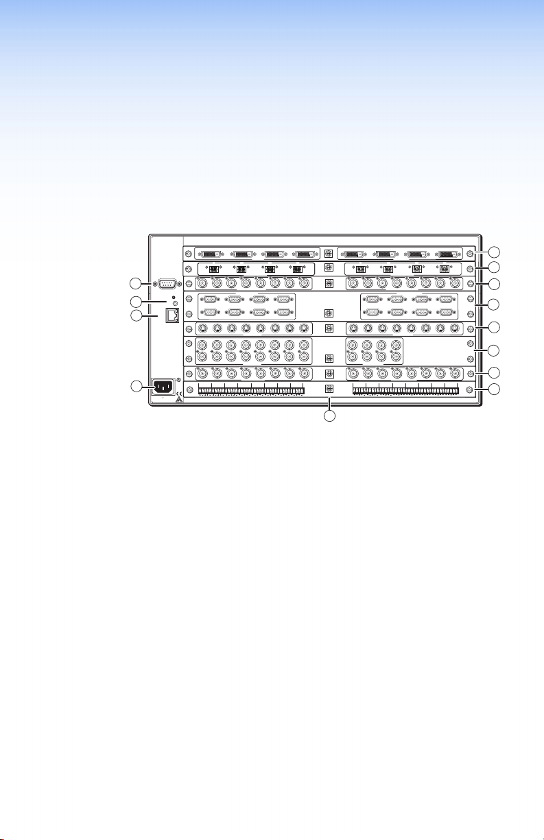
Figure 1. Typical Matrix Switcher Application (5U Unit)
LR
Board Type I/O Connector
Composite
S-Video 8x4(2) 8x8(2) 16x16(4)
SDI and HD-SDI 4x4(1) 8x4(1) 8x8(1) 16x16(2)
Ultra Wideband 8x4(1) 8x8(1) 16x16(2)
BNC
Sync 8x8(1)
Audio Captive
Screw
DVI
DVI-Pro 4x4(1) 4x8(2) 8x4(2) 8x8(2)
DVI-I
S-Video Mini DIN 8x4(1) 8x8(1) 16x16(2)
HDMI HDMI 4x4(1) 4x8(2) 8x4(2) 8x8(2)
Wideband VGA 15-pin HD 8x4(2) 8x8(2) 16x16(4)
Fiber Optic
(singlemode)
Fiber Optic
(multimode)
USB USB B in
2 SMX System MultiMatrix Switcher • Introduction
Optical
(SFP)
USB A out
Board Names
Board Sizes (Slots Used)
8x4(1) 8x8(1) 16x16(2)
8x4(1) 8x8(1) 16x16(2)
4x4(1) 4x8(2) 8x4(2) 8x8(2)
4x4(1) 8x4(1)
H or V
8x8(2)
16x16(2)
H or V
HV
8x8(1) 16x16(2)
8x8(1) 16x16(2)
Page 9
Installation
This section provides procedures for setting up the SMX and wiring
audio connectors. Topics in the section include:
• Rear Panel
• Wiring Audio Connectors
Rear Panel
2
1
1
1
IN
IN
OUT
OUT
OUT
REMOTE
4
RS232/RS422
3
2
1
100-240V , 50-60Hz
2.0A MAX.
OUT
2
14
1
RESET
LINK
LAN
5
ACT
14
14
14
®
US
LISTED
IT23
L 1 R
L 2 R
I.T.E.
2
2
2
L 3 R
3
INPUTS
3
3
2
2
OUT
OUT
IN
IN
FIBER OPTIC
FIBER OPTIC
5
3
SDI / HDSDI INPUTS
COMPUTER IN
3
2
6
7
5
3
S-VIDEO IN
14
3
S-VIDEO IN
5
3
VIDEO INPUTS
L 5 R
L 4 R
L 6 R
4
PLANE ADRESS
4
4
OUT
OUT
IN
IN
IN
IN
PLANE ADRESS
DIGITAL VIDEO
8
7
6
6
2
6
L 7 R
PLANE ADRESS
4
8
PLANE ADRESS
8
7
PLANE ADRESS
S-VIDEO
Y
Y
3
C
C
PLANE ADRESS
WB VIDEO
8
7
PLANE ADRESS
L 8 R
PLANE ADRESS
2
1
OUT
OUTPUTS
2
1
IN
OUT
OUT
IN
FIBER OPTIC
2
14
3
2
14
3
SDI / HDSDI OUTPUTS
COMPUTER OUT
1
2
6
5
2
14
3
S-VIDEO OUT
2
14
3
S-VIDEO OUT
2
14
3
2
14
3
VIDEO OUTPUTS
L 5 R
L 4 R
L 1 R
L 3 R
L 2 R
3
3
OUT
IN
5
6
5
6
3
7
5
6
5
6
5
6
L 7 R
L 6 R
13
Figure 2. An Example of a 5U SMX Rear Panel
AC power connector
a
LAN Ethernet port
b
Reset button and LED
c
Remote serial port
d
- l I/O boards (optional)
e
Plane address switch
m
Connecting Inputs
Connect compatible AV sources to the applicable I/O board
connectors marked "Inputs" (see the table on page 2 for connector
and signal types).
Connecting Outputs
Connect compatible AV output devices to the applicable I/O board
connectors marked "Outputs" (see the table on page 2 for connector/
signal types or see Wiring Audio Connectors on page 4 for audio
connector wiring details).
4
4
7
7
4
8
7
5
IN
6
7
8
8
8
9
8
10
11
8
7
8
7
L 8 R
12
Connecting Control Devices
LAN Ethernet port — Connect to an Ethernet LAN or WAN through
the RJ-45 connector on the rear panel to control the SMX using a PC
(see b in gure 2).
SMX System MultiMatrix Switcher • Installation 3
Page 10
The Ethernet connection indicator LEDs marked "Link" and "Act"
ADDRESS
indicate the status of the SMX Ethernet connection. The Link LED
lights green when connected to an Ethernet LAN, and the Act LED
flickers amber, as the devices communicate.
NOTE: Do not use standard telephone cables, as they do not
support Ethernet or fast Ethernet. Do not stretch or bend
cables as transmission errors could occur.
Remote port — For serial RS-232 or RS-422 control, connect a host
computer or control system through this 9-pin D connector. RS-232
protocol (default values):
• 9600 baud • 1 stop bit • no parity • 8 data
• no flow
bits
NOTE: See the SMX User Guide for more details.
Connecting Power
Plug in a standard IEC power cord from a 100 to 240 VAC, 50-60 Hz
power source into the rear panel.
Setting Plane Addresses
Set the plane address (0-15) of each I/O board with the
16 position (0-F) rotary encoder. Each board can be set
to any plane address, including multiple boards to the
same address.
Installing Additional I/O Boards
The I/O boards used in any installation will vary and can be installed
and changed as desired.
NOTE: All boards are hot-swapable and can be installed without
shutting down the SMX or removing the power.
control
See Installing New Boards on page 38 to reconfigure or populate the
SMX frame.
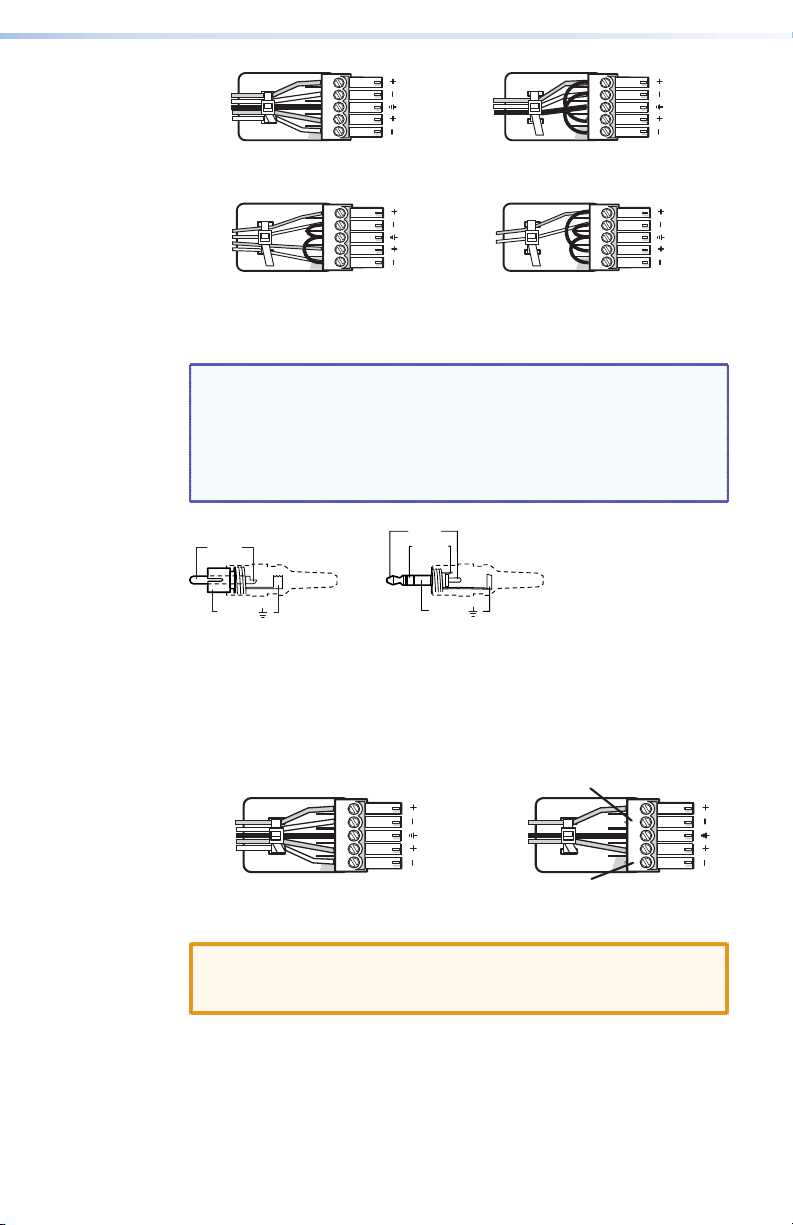
Wiring Audio Connectors
Audio input connectors — Connect audio input devices to the
3.5 mm, 5-pole captive screw connectors (up to two groups of eight
sets possible). Wire the input connector for the appropriate signal
type (see gure 3).
Do not tin the wires!
4 SMX System MultiMatrix Switcher • Installation
Page 11
Tip
3.5 mm Stereo Plug Connector
(balanced)
LR
LR
Ring
Sleeves
Tip
Ring
Balanced Stereo Input
Tip
Sleeve
Tip
Sleeve
LR
Sleeve
LR
Sleeve
Tip
Ring
Balanced Mono Input
(high impedance)
Tip
LR
LR
Unbalanced Stereo Input
Unbalanced Mono Input
Figure 3. Audio Input Captive Screw Wiring
NOTES: • A mono audio connector consists of the tip and sleeve,
whereas a stereo audio connector consists of the tip,
ring, and sleeve. The tip, ring, and sleeve wires are
also shown in figure 4 (balanced inputs).
• See the SMX User Guide for details about setting up
the audio.
Tip (+)
Tip (+)
Sleeve ( )
RCA Connector
Ring (-)
Sleeve ( )
Figure 4. Audio Connectors
Audio output connectors — Connect audio output devices to the
3.5 mm, 5-pole captive screw connectors (up to two groups of eight
sets possible). The connectors output unamplified, line level audio
(see gure 5 for wiring details).
Tip
Ring
Sleeves
Tip
Ring
No Ground Here
Tip
Sleeves
Tip
No Ground Here
Figure 5. Audio Output Captive Screw Wiring
CAUTION: For unbalanced audio, connect the sleeves to the
center contact ground. Do not connect the sleeves to
the negative (-) contacts.
5SMX System MultiMatrix Switcher • Installation
Page 12

Front Panel Operation
This section details the physical configuration and front panel
operation of the SMX after the installation process and includes:
• Front Panel Overview
• Creating Ties
• Viewing Ties
• Muting or Unmuting Outputs
• Removing Ties
• Saving and Recalling I/O Presets
• Adjusting the Input Audio Level
• Adjusting the Output Audio Volume
• Using Reset Levels
• Setting the Front Panel Locks (Executive Modes)
Front Panel Overview
1
4
4
5
5
6 7 8
5
6 7 8
6 7 8
I/O PLANE SELECT
INPUTS
OUTPUTS
3
9
11 12 13 14 15
10
10
9
11 12
10
9
11 12 13 14 15 16
13 14 15 16
CONFIG
CONTROL
ENTER PRESET
6
ESC
VIEW
P
MAIN
O
W
E
I/O CARDS
R
SMX SERIES SWITCHER
5
2
1
3
0
2
2
1
3 4
2
1
3 4
Figure 6. Front Panel Features
I/O Plane address selection buttons — Select I/O planes (0-15), and
a
buttons 0 and 1 select RS-232 or RS-422 communication.
Input selection buttons — Select inputs, create and remove ties,
b
sets background illumination (press and hold inputs 0 and 1), or
indicate output audio volume.
Output selection buttons — Select outputs, create and remove
c
ties, and indicate input audio gain/attenuation.
NOTE: Input buttons are can also be used to save and recall
global and plane presets.
Control buttons — Enter, Preset, View, and Esc. Used to configure
d
unit; save and recall presets; create, remove, and view ties; adjust
audio volume and gain; switch lock modes; configure ports; and
reset the SMX.
SMX System MultiMatrix Switcher • Front Panel Operation6
Page 13
e
f
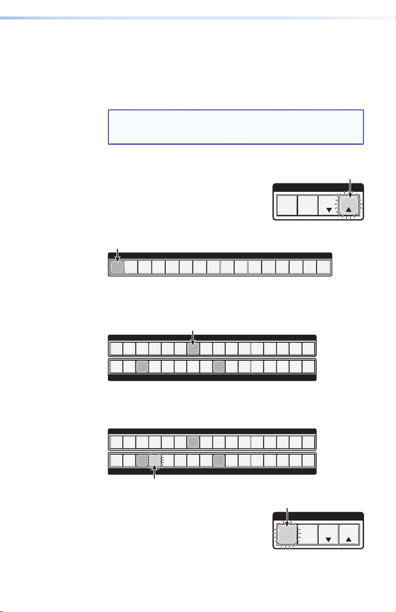
Creating Ties
1. Press the Esc button to clear any pending
2. Press the I/O Plane button that
3. Press the Input button that corresponds to the desired input
Power status LEDs — Indicate power status for the main unit and
I/O boards.
Front panel configuration port — Connects a control system or
computer to this (RS-232) port, using an optional 9-pin D to
2.5 mm mini jack TRS RS-232 cable, part number 70-335-01. RS-232
protocol (default values): • 9600 baud • 1 stop bit • no parity
• 8 data bits • no flow control
NOTE: Unless specified otherwise, buttons on the SMX light
green for video boards, red for audio boards, and
amber for audio and video boards.
changes. The button flashes green once.
ENTER
C O N T R O L
PRESET
ESCVIEW
corresponds to the plane address of the
desired I/O board. The Plane button along with Input 1 and any of
its tied Output buttons light.
I/O PLANE SELECT
2
1
0
4
3
5
6 7 8
9
11 12 13 14 15
10
Figure 7. Plane 0 Selected — an Example
source. The selected button lights along with any currently tied
outputs.
INPUTS
2
1
4
3
5
6 7 8
10
9
11 12
13 14 15 16
2
1
4
3
5
6 7 8
OUTPUTS
10
9
11 12 13 14 15 16
Figure 8. Input 7 with Tied Outputs 3 and 9 — an Example
4. Press unlit Output buttons that correspond to the desired output
devices. Selected output buttons and the Enter button flash.
INPUTS
2
1
1
4
3
2
3
6 7 8
5
4
6 7 8
5
OUTPUTS
10
9
11 12
10
9
11 12 13 14 15 16
13 14 15 16
Figure 9. Input 7 with Tied Output 3 and 9 with a Pending Tie
to Output 4 — an Example
ENTER
C O N T R O L
PRESET
ESCVIEW
5. Press the Enter button. All button lights
turn off.
7SMX System MultiMatrix Switcher • Front Panel Operation
Page 14
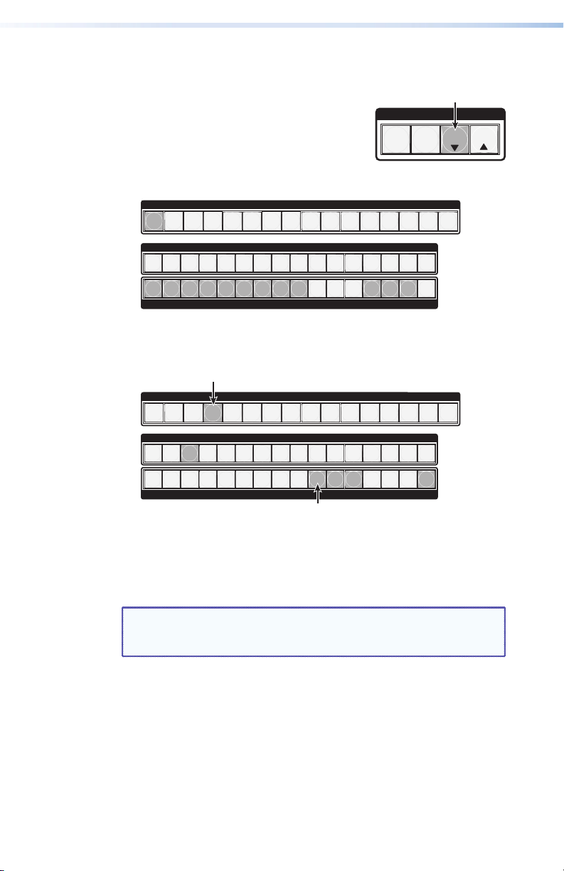
Viewing Ties
1. Press the Esc button to clear any pending changes. The button
2. Press the View button. The last selected
3. Press the I/O Plane button that corresponds to the plane address
flashes once.
Plane button and untied, unmuted
C O N T R O L
PRESET
buttons light. Untied and muted buttons
ENTER
flash.
of the desired I/O board. Buttons light as specified in step 2.
I/O PLANE SELECT
0
2
1
2
1
3
4
3
4
5
6 7 8
5
6 7 8
INPUTS
9
11 12 13 14 15
10
10
9
11 12
13 14 15 16
ESCVIEW
2
1
4
3
5
6 7 8
Figure 10. Plane 0 Showing Untied, Unmuted Outputs 1 though
9 and 13 through 15 — an Example
4. To view inputs tied to an output, press either the desired Input
button or an unlit Output button.
0
2
1
2
1
3
2
1
3
4
3
4
5
4
5
6 7 8
5
6 7 8
6 7 8
Figure 11. Plane 3 Showing Tied Outputs 10 through 12 and 16
on Input 3 — an Example
5. Press the Esc button. All button lights turn off.
Muting or Unmuting Outputs
NOTE: When the front panel is in lockout mode 2, the output
1. Press the Esc button to clear any pending changes. The button
2. Press the View button. The last selected Plane button and untied,
3. Press the I/O Plane button that corresponds to the plane address
mute status can be only be viewed. No changes can be
made from the front panel.
flashes once.
unmuted buttons light. Untied and muted buttons flash.
of the desired I/O board. Buttons light as specified in step 2.
10
9
OUTPUTS
I/O PLANE SELECT
INPUTS
10
9
10
9
OUTPUTS
11 12 13 14 15 16
9
11 12 13 14 15
10
13 14 15 16
11 12
11 12 13 14 15 16
8 SMX System MultiMatrix Switcher • Front Panel Operation
Page 15
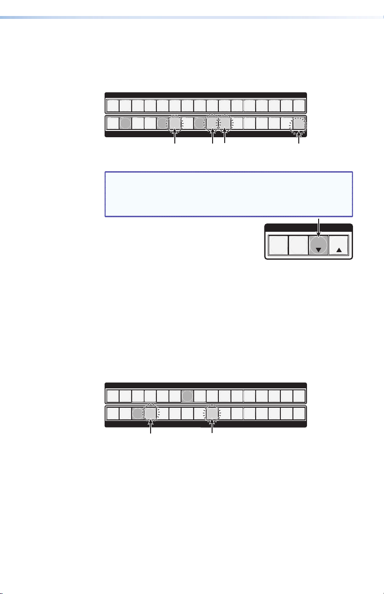
4. Perform one of the following:
• To mute outputs, press and hold lit or unlit output buttons for
2 seconds.
• To unmute outputs, press and hold flashing output buttons for
2 seconds.
INPUTS
2
1
4
3
5
6 7 8
10
9
11 12
13 14 15 16
1
Figure 12. Unmuted Outputs 2, 5, and 8 and Muted Outputs 6, 9,
NOTE: For video, only RGB is muted. Sync is not muted.
5. Press the View button. All button lights
turn off.
Removing Ties
1. Press the Esc button to clear any pending changes. The button
flashes once.
2. Press the I/O Plane button that corresponds to the plane address
of the desired I/O board. The Plane button along with Input 1 and
any of its tied Output buttons light.
3. Press the Input button that corresponds to the desired input
source. Only the last selected Input button lights along with any
currently tied outputs.
4. Press lit Output buttons that correspond to the desired output
devices. Selected output buttons and the Enter button flash.
1
2
4
3
5
6 7 8
OUTPUTS
10
9
11 12 13 14 15 16
10, and 16 — an Example
For RGBHV systems, only the R, G, and B boards are
muted. The H and V boards remain active. All tied and
untied outputs can be muted.
C O N T R O L
ENTER
PRESET
INPUTS
2
4
3
5
6 7 8
10
9
11 12
13 14 15 16
ESCVIEW
2
1
4
3
5
6 7 8
OUTPUTS
10
9
11 12 13 14 15 16
Figure 13. Input 7 with Tied Output 3, 4, and 9 with Pending
Removal of Output 4 and 9 — an Example
5. Press the Enter button. All button lights turn off.
9SMX System MultiMatrix Switcher • Front Panel Operation
Page 16

Saving and Recalling I/O Presets
Save current configurations as global or plane presets to save audio
and video ties. The SMX has 32 global preset (using I/O buttons 1-16)
and 10 plane presets (input buttons 1-10) addresses available.
Global preset — Saves and recalls configurations for all planes (see
gure 14 for global preset addresses).
Plane preset — Saves and recalls the configurations for a specific
plane without affecting the other plane connections (see gure 14
for plane preset addresses).
PLANE
GLOBAL
GLOBAL
ENTER
NOTES: • Presets cannot be viewed from the front panel unless
recalled as the current configuration (see the User
Guide for ways to view presets).
• The current configuration and all presets are retained
when power is removed and then restored.
• Recalled presets override current configurations.
• Audio gain settings are not saved with presets.
Preset
1
Preset
1
Preset
2
Preset
2
Preset3Preset
Preset3Preset
Preset5Preset
4
Preset5Preset
4
INPUTS
Preset
10
9
Preset
Preset11Preset
10
9
Preset13Preset14Preset
12
15
Preset
7
Preset
7
Preset8Preset
Preset8Preset
6
6
1 2 3 4 5 6 7 8 9 10 11 12 13 14 15 16
1 2 3 4 5 6 7 8 9 10 11 12 13 14 15 16
OUTPUTS
Preset
Preset
18
Preset19Preset
17
Figure 14. Global and Plane Preset Addresses
Saving or Recalling a Global Preset
1. Press the Esc button to clear any pending changes. The button
flashes once.
2. Perform one of the following:
C O N T R O L
PRESET
ESCVIEW
Figure 15. Saved Global Presets 8, 18, and 32 — an Example
Preset21Preset
20
Preset
3
3
23
4
4
Preset24Preset
5
5
22
2
1
2
1
Preset
25
6 7 8
6 7 8
Preset27Preset
26
INPUTS
OUTPUTS
Preset29Preset30Preset
28
10
9
11 12
10
9
11 12 13 14 15 16
31
13 14 15 16
Preset
16
Preset
32
• To save a global preset, press and hold the Preset button for
2 seconds. The Preset button flashes red.
• To recall a global preset, press and release the Preset button.
The Preset button lights red.
10 SMX System MultiMatrix Switcher • Front Panel Operation
Page 17

3. Pick a global preset number (see gure 14) and perform one of
the following:
• To save a global preset, press the desired input or output
button. This overwrites a previously saved global preset.
• To recall a global preset, press the desired lit input or lit output
button.
INPUTS
2
1
4
3
5
6 7 8
10
9
11 12
13 14 15 16
2
1
4
3
5
6 7 8
OUTPUTS
10
9
11 12 13 14 15 16
Figure 16. Global Preset 21 Selected — an Example
Upon selection, the button and the Enter
button flash red.
4. Press the Enter button to save or recall
ENTER
C O N T R O L
PRESET
presets.
Saving or Recalling a Plane Preset
1. Press the Esc button to clear any pending changes. The button
flashes once.
2. Perform one of the following:
a. To save a plane preset, press and hold the Preset button for 2
seconds. The Preset button flashes red.
b. To recall a plane preset, press and release the Preset button.
The Preset button lights red.
3. Press the desired plane button. The button lights and any saved
plane presets light red.
4. Pick a plane preset number (see gure 14) and perform one of the
following:
• To save a plane preset, press the desired input button. The
selected button and the Enter button flash red.
• To recall a plane preset, press the desired lit Input button. The
selected button and the Enter button flash red.
INPUTS
2
1
4
3
5
6 7 8
10
9
11 12
13 14 15 16
ESCVIEW
2
1
4
3
5
6 7 8
OUTPUTS
10
9
11 12 13 14 15 16
Figure 17. Plane Preset 7 with Plane Preset 3 Selected — an
Example
5. Press the Enter button to save or recall the
C O N T R O L
plane preset.
ENTER
PRESET
ESCVIEW
11SMX System MultiMatrix Switcher • Front Panel Operation
Page 18

Adjusting the Input Audio Level
The audio level of each input can be displayed and adjusted through
a range of -18 dB to +24 dB. The level can be adjusted from the front
panel, RS-232, RS-422, or Ethernet connection.
NOTE: Refer to the SMX User Guide for other adjustment
methods.
1. Press the Esc button to clear any pending changes. The button
flashes green once.
2. Press the desired audio I/O Plane button to be adjusted. The plane
button and an Input button light.
I/O PLANE SELECT
2
1
0
4
3
5
6 7 8
9
11 12 13 14 15
10
Figure 18. Plane 4 Selected — an Example
3. Press and hold any Input button until the I/O Plane button flashes.
Input and Output buttons turn off.
4. Press the button for the input that needs the audio level adjusted.
The selected input button lights green, and the View button lights
red. The current audio level dB is indicated by the lit and flashing
output buttons (see Input Audio Level Table on page 13).
INPUTS
2
1
1
4
3
2
3
6 7 8
5
4
6 7 8
5
OUTPUTS
10
9
11 12
10
9
11 12 13 14 15 16
13 14 15 16
Figure 19. Input 8 Set to -09 dB — an Example
5. Press and hold the View button to decrease or the Esc button to
increase audio level.
ENTER
C O N T R O L
PRESET
ESCVIEW
ENTER
C O N T R O L
PRESET
ESCVIEW
or
The selected Input button remains lit. Outputs light, flash, or go
out as the level changes (see Input Audio Level Table on
page 13 for button lighting and dB levels). Additional inputs can
be adjusted by repeating steps 4 and 5.
NOTE: The View button lights only when the current audio
level is negative dB, and the Esc button lights only
when it is positive dB.
6. Press the Enter button to leave the input audio level adjustment
mode. All button lights go out.
12 SMX System MultiMatrix Switcher • Front Panel Operation
Page 19

Input Audio Level Table
dB Color Output Buttons Lit
or Flashing
24 green 12
23 green 12 flash
22 green 11
21 green 11 flash
20 green 10
19 green 10 flash
18 green 9
17 green 9 flash
16 green 8
15 green 8 flash
14 green 7
13 green 7 flash
12 green 6
11 green 6 flash
10 green 5
09 green 5 flash
08 green 4
07 green 4 flash
06 green 3
05 green 3 flash
04 green 2
03 green 2 flash
02 green 1
01 green 1 flash
00 Not lit
+/- dB Color Output Buttons Lit
-01 red 1 flash
>
-02 red 1 flash
>
-03 red 2 flash
>
-04 red 2 flash
>
-05 red 3 flash
>
-06 red 3 flash
>
-07 red 4 flash
>
-08 red 4 flash
>
-09 red 5 flash
>
-10 red 5 flash
>
-11 red 6 flash
>
-12 red 6 flash
>
-13 red 7 flash
>
-14 red 7 flash
>
-15 red 8 flash
>
-16 red 8 flash
>
-17 red 9 flash
>
-18 red 9
>
>
>
>
>
>
>
or Flashing
= Esc
>
= View
<
+/-
<
<
<
<
<
<
<
<
<
<
<
<
<
<
<
<
<
<
NOTES: • There is only one audio level setting per input and
one per output on an audio plane. The audio level
and volume is shared by the left and right inputs and
outputs.
• Audio levels and volumes are stored in nonvolatile
memory. When power is removed or restored, settings
are retained.
13SMX System MultiMatrix Switcher • Front Panel Operation
Page 20

Adjusting the Output Audio Volume
The audio output level of each output can be displayed and adjusted
through a range of 64 steps (1 dB per step, 0% to 100%). The audio
level can be adjusted from the front panel, RS-232, RS-422, or through
Ethernet. Adjustment is attenuation only.
NOTES: • Refer to the SMX User Guide for other adjustment
methods.
• Front panel adjustment and viewing are only available
when the unit is in Lock mode 0.
1. Press the Esc button to clear any pending changes. The button
flashes green once.
2. Press the desired audio I/O Plane button to be adjusted. The plane
button and Input 1 light.
I/O PLANE SELECT
2
1
0
4
3
5
6 7 8
9
11 12 13 14 15
10
Figure 20. Plane 4 Selected — an Example
3. Press and hold any Ouput button until the I/O Plane button
flashes. I/O buttons turn off.
4. Press the button for the output that needs the audio volume
adjusted. The selected output button lights green. The current
audio volume is indicated by the lit and flashing Input buttons
(see the Output Audio Volume Table on page 15 for lighting and
volume levels).
INPUTS
2
1
1
4
3
2
3
6 7 8
5
4
6 7 8
5
OUTPUTS
10
9
11 12
10
9
11 12 13 14 15 16
13 14 15 16
Figure 21. Output 3 Set to 100% Audio Volume — an Example
5. Press and hold the View button to decrease or the Esc button
to increase audio level. The selected output button remains lit.
Inputs light, flash, or go out as the volume changes.
INPUTS
2
1
1
4
3
2
3
6 7 8
5
4
6 7 8
5
OUTPUTS
10
9
11 12
10
9
11 12 13 14 15 16
Figure 22. Output 3 Set to 67.0% Audio Volume — an Example
6. Press the Enter button to leave the output audio volume
adjustment mode. All button lights turn off.
14 SMX System MultiMatrix Switcher • Front Panel Operation
13 14 15 16
Page 21

Output Audio Volume Table
Volume
%
dB
Attenuation
100 0 16
Buttons
Lit or
Flashing
SIS
Command
plane*out#
*64V
Volume
%
dB
Attenuation
52.0 32 8
Buttons
Lit or
Flashing
Command
plane*out#
98.5 1 16 63 50.5 33 8 31
97.0 2 slow 62 49.0 34 slow 30
95.5 3 slow 61 47.5 35 slow 29
94.4 4 15 60 46.0 36 7 28
92.5 5 15 59 44.5 37 7 27
91.0 6 slow 58 43.0 38 slow 26
89.5 7 slow 57 41.5 39 slow 25
88.0 8 14 56 40.0 40 6 24
86.5 9 14 55 38.5 41 6 23
85.0 10 slow 54 37.0 42 slow 22
83.5 11 slow 53 35.5 43 slow 21
82.0 12 13 52 34.0 44 5 20
80.5 13 13 51 32.5 45 5 19
79.0 14 slow 50 31.0 46 slow 18
77.5 15 slow 49 29.5 47 slow 17
76.0 16 12 48 28.0 48 4 16
74.5 17 12 47 26.5 49 4 15
73.0 18 slow 46 25.0 50 slow 14
71.5 19 slow 45 23.5 51 slow 13
70.0 20 11 44 22.0 52 3 12
68.5 21 11 43 20.5 53 3 11
67.0 22 slow 42 19.0 54 slow 10
65.5 23 slow 41 17.5 55 slow 9
64.0 24 10 40 16.0 56 2 8
62.5 25 10 39 14.5 57 2 7
61.0 26 slow 38 13.0 58 slow 6
59.5 27 slow 37 11.5 59 slow 5
58.0 28 09 36 10.0 60 1 4
56.5 29 09 35 8.5 61 1 3
55.0 30 slow 34 7.0 62 slow 2
53.5 31 slow
plane*out#
*33V
5.5 63 slow
plane*out#
0 76 not lit 0
SIS
*32V
*1V
15SMX System MultiMatrix Switcher • Front Panel Operation
Page 22

Using Reset Levels
1
2
utton.
The rear panel has a recessed Reset button (see page 3) that initiates
four levels of resets (numbered 1, 3, 4, and 5). Use a pointed stylus,
ballpoint pen, or Extron Tweeker to access it and select the reset level.
See the Reset Mode Table on page 17 for a summary of the modes.
CAUTION: Review the reset modes carefully. Using the wrong
reset mode may result in unintended loss of flash
memory programming, port reassignment, or a
controller reboot.
NOTES: • The reset modes listed below close all open IP and
Telnet connections and sockets. Also, the following
modes are separate functions, not a continuation from
mode 1 to mode 5.
• If the reset button is continuously held down, the I/O
lights flash every 3 seconds as the next reset level is
reached, corresponding to modes 3, 4, and 5.
Reset Mode Uses
Use mode 1 to revert to the factory default firmware version if
compatibility issues arise with user-loaded firmware (see notes on
page 17).
Use mode 3 to restart the communication and control events.
Use mode 4 to reset most IP protocols to their default settings.
Use mode 5 to restore the switcher to the default conditions.
NOTE: Mode 5 reset clears most adjustment. To save these
settings, use the SMX Control Program and the File >
Save MATRIX settings as... selection before you
perform this reset (see Conguration and Control on
page 32).
Mode 1
Press and hold
the Reset button.
Modes 3, 4, and 5
Press and hold for
3, 6, or 9 seconds.
16 SMX System MultiMatrix Switcher • Front Panel Operation
RESET
Reset LED flashes once,
twice, or three times.
RESET
RESET
Release the Reset b
Apply Power
RESET
Release, then immediately
press and release again. Reset
LED flashes in confirmation.
RESET
Page 23

Reset Mode Table
Mode Action Result
1 Hold down the recessed
Reset button while applying
power to the switcher.
Defaults switcher to factory installed
firmware. Event scripting will not start if
the switcher is powered on in this mode. All
user files and settings (drivers, adjustments,
IP settings, and so on) are maintained (see
notes below).
3 Hold down the Reset button
for 3 seconds, until the Reset
LED blinks once, then press
Reset momentarily
Mode 3 turns events on or off. During
resetting, the Reset LED flashes 2 times if
events are starting, 3 times if events are
stopping.
(<1 second) within 1 second.
4 Hold down the Reset button
for 6 seconds, until the Reset
LED blinks twice (once at 3
seconds, again at 6 seconds)
then press Reset momentarily
(<1 second) within 1 second.
Mode 4:
• Enables ARP capability
• Sets IP address to factory default
• Sets subnet address to factory default
• Sets gateway address to factory default
• Sets port mapping to factory default
• Turns DHCP off
• Turns events off
The Reset LED flashes four times in quick
succession confirming the Reset.
5 Hold down the Reset button
for 9 seconds, until the Reset
LED blinks three times (once
at 3 seconds, again at 6
seconds, and then again at
9 seconds). Then press Reset
momentarily (<1 second)
within 1 second.
Mode 5 performs a complete reset to
factory defaults (with the exception of the
firmware):
• Does everything mode 4 does
• Resets almost all real time adjustments:
clears all ties and presets, clears all audio
or RS-232 mutes, clears all I/O grouping,
clears all RGB delay settings to zero, and
clears all input and output audio settings
(see the SMX User Guide for more details
on these features)
• Resets all IP options
• Removes/clears all files for the SMX
The reset LED flashes four times in quick
succession confirming the reset.
NOTES: • After a mode 1 reset is performed, update the firmware
to the latest version. Do not operate the SMX firmware
version that results from the mode 1 reset. To use factory
default firmware, upload that version again.
• If you do not want to update firmware, or you performed
a mode 1 reset by mistake, cycle power to the SMX to
return to the firmware version that was running before
the mode 1 reset. Use the 0Q SIS command to confirm
that the factory default firmware is no longer running
(look for the asterisk [*] following the version number.
17SMX System MultiMatrix Switcher • Front Panel Operation
Page 24

Setting the Front Panel Locks (Executive Modes)
The SMX has three levels of front panel security lock.
Lock mode 0 — The front panel is completely unlocked and all basic
and advanced features are available.
Lock mode 1 (Executive mode) — All changes are locked from the
front panel (except for View mode and setting Lock mode 2).
Lock mode 2 (Advanced Executive mode) — Basic functions are
unlocked. Advanced features are locked and can be viewed only
(default mode).
NOTE: The SMX is shipped from the factory in Lock mode 2.
Basic features consist of making ties, saving and recalling presets,
setting input audio gain and attenuation, and changing lock modes.
Advanced features consist of setting video and audio output mutes,
setting audio output volume, setting RGB delay (VGA, RGBHV
boards), and setting the rear panel remote port protocol and baud
rate (see the SMX User Guide to adjust many of these features).
Selecting Lock Mode 2 or Toggling Between Mode 2
and Mode 0
Press and hold the Preset, View, and Esc buttons
at the same time for 2 seconds to switch
between lock mode 0 and 2.
The Preset, View, and Esc buttons flash green
twice to indicate Lock Mode 2 is enabled.
The View and Esc buttons flash green twice to indicate lock mode 0 is
enabled.
Selecting Lock Mode 1 or Toggling Between Mode 2
and Mode 1
Press and hold the View and Esc buttons at the
same time for 2 seconds to switch between lock
mode 0 and 1.
The View and Esc buttons flash green twice to
indicate lock mode 1 is enabled.
The Preset, View, and Esc buttons flash green twice to indicate lock
mode 2 is enabled.
ENTER
ENTER
PRESET
PRESET
C O N T R O L
ESCVIEW
C O N T R O L
ESCVIEW
18 SMX System MultiMatrix Switcher • Front Panel Operation
Page 25

SIS Programming
Guide
The SMX uses SIS commands for operation and configuration. These
commands can be run from a PC connected to either of the SMX serial
ports or the Ethernet port. See b and d on page 3, and f on page 7
for connection information.
NOTE: The tables that begin on page 22 are a partial list of SIS
This section describes selected SIS Commands and includes:
• SIS Overview
• SIS Command Tables
SIS Overview
Network (Ethernet) Connections
1. Open a TCP socket to port 23 using the SMX IP address
2. If the SMX is not password-protected, the device is now ready to
Connection time-outs
The Ethernet link disconnects after a designated period of no
communications. By default, this time-out value is set to 5 minutes
but the value can be changed.
commands (see the SMX User Guide for a complete list).
NOTE: The factory default IP address is 192.168.254.254.
The SMX responds with a copyright message including the date,
the name of the product, firmware version, part number, and the
current date and time.
accept SIS commands.
If the SMX is password-protected, enter the appropriate password.
If accepted, the SMX responds with Login User or Login
Administrator. If the password is not accepted, the Password
prompt reappears.
NOTE: Extron recommends leaving the default time-out at 5
minutes and periodically issuing the Query (Q) command
to keep the connection active or disconnecting the socket
and reopening the connection when necessary.
SMX System MultiMatrix Switcher • SIS Programming Guide 19
Page 26

Number of connections
An SMX can have up to 200 simultaneous TCP connections, including
all HTTP sockets and Telnet connections. When the limit is reached,
the SMX accepts no new connections until some have been closed. No
error message or indication is given that the limit has been reached.
To maximize performance unnecessary open sockets should be closed.
Verbose Mode
Telnet connections can be used to monitor changes that occur on
the SMX. The Telnet session must be in verbose mode 1 or 3. See the
Verbose Mode commands on page 31.
Host-to-switcher Instructions
SIS commands consist of one or more characters per command
field and do not require any special characters to begin or end the
sequence. SMX responses to an SIS command ends with a carriage
return and a line feed, which signals the end of the character string
(a string is one or more characters).
] = CR/LF (carriage return/line feed)
} = Carriage return (no line feed)
= Space character
•
NOTES: • Commands can be entered back-to-back
in a string with no spaces. For example:
1*1&001*002*002&001*003*
003&001
• The SMX supports 1-, 2-, and 3-digit numeric entries
(1*1*1!, 01*02*02&, or 001*003*003%).
Error Messages
E01 = Invalid input number E24 = Privilege violation
E10 = Invalid command E25 = Device no present (invalid plane/slot)
E11 = Invalid preset number E26 = Maximum number of connections exceeded
E12 = Invalid output number E27 = Invalid event number
E13 = Invalid parameter E28 = Bad filename/file not found
E14 = Invalid for this
configuration
20 SMX System MultiMatrix Switcher • SIS Programming Guide
Page 27

SIS Value
X3@
1
2
3
4
5
6
7
8
9
10
11
12
13
14
15
16
17
18
19
20
EDID — Extended Display Identication Data
A communications protocol or instruction set for the identification of
display devices to computers using the DDC (Display Data Channel)
transmission standard (see page 28 for SIS commands).
EDID Minder Table — DDC Source Selection DVI-Pro/HDMI
Resolution Refresh
Output 1
Output 2
Output 3
Output 4
Output 5
Output 6
Output 7
Output 8
640x480
640x480
800x600
800x600
852x480
852x480
1024x768
(default)
DVI
1024x768
1024x852
1024x852
1280x768
1280x768
(Hz)
SIS Value
X3@
21
22
23
24
25
Resolution Refresh
1280x1024
1280x1024
1365x768
1365x768
1366x768
26 1366x768 75
27 1400x1050 60
28 1600x1200 60
60 29 480p 60
75 30 576p 50
60 31 720p 50
75 32
720p (default)
DVI-Pro/HDMI
60 33 1080i 50
75 34 1080i 60
60 35 1080p 50
75 36 1080p 60
60 37
75 38
60 39
75 40
User assigned
User assigned
User assigned
User assigned
Resolution Refresh
(Hz)
60
75
60
75
60
2 ch audio
2 ch audio
2 ch audio
60
(default)
2 ch audio
1080p
Multi ch
2 ch audio
1080p
2 ch audio
1080p
2 ch audio
(Hz)
480p
576p
720p
720p
audio
1080i
60
60
50
60
60
60
50
60
21SMX System MultiMatrix Switcher • SIS Programming Guide
Page 28

on plane
on plane
X#
X#
to output
to output
X@
X@
on plane
on plane
X#
X#
to output
to output
X@
X@
to all outputs on plane
to all outputs on plane
to all outputs on plane
X@
X@
to all outputs on plane
X@
X@
for RGB signals.
Additional Description
X2@
• RGB] Tie input
X@
•In
X#
Out
Response
(switcher to host)
(host to switcher)
X2@
&
X#
*
X@
*
X2@
for video signals.
for audio signals.
X2@
X2@
• Vid] Tie input
• Aud] Tie input
X@
X@
•In
•In
X#
X#
Out
Out
X2@
X2@
%
$
X#
X#
*
*
X@
X@
*
*
X2@
X2@
for all signals.
X2@
• All] Tie input
X@
•In
X#
Out
X2@
!
X#
*
X@
*
X2@
for RGB signals.
for video signals.
X2@
X2@
• RGB] Tie input
• Vid] Tie input
X@
X@
In
In
X2@
X2@
*&
*%
X@
X@
*
*
X2@
X2@
, all signals.
for audio signals.
X2@
X2@
• Aud] Tie input
• All] Tie input
X@
X@
In
In
X2@
X2@
*$
*!
X@
X@
*
*
X2@
X2@
The ! tie command can be used for switching both video signals and audio signals with the same plane address.
NOTES: The & tie command for RGBHV and the % command for video can be used interchangeably.
Tie input to an output (RGBHV)
Tie input to an output (video)
Tie input to an output (audio)
Command ASCII Command
SIS Command Tables
22 SMX System MultiMatrix Switcher • SIS Programming Guide
Output Switching by Plane
Tie input to an output (all)
The & read tie command for RGB and the % read tie command for video can be used interchangeably.
NOTES: The & tie command for RGB and the % tie command for video can be used interchangeably.
Tie input to all (RGBHV)
Tie input to all (video)
Tie input to all (audio)
Tie input to all (audio and video)
X# = Output number 01 - <maximum number of outputs>
X2@ = Plane number 00 - 15, 90 - 99 (virtual plane)
NOTES: X@ = Input number 01 - <maximum number of inputs>, 00 = untied
Page 29

X#
X#
.
.
.
X#
X#
X#
Additional Description
Response
Make multiple ties with one
command entry.
Tie plane 1 input 3 to outputs 4, 5,
and 6.
(switcher to host)
Qik]
Qik]
!
X#
*
$}
X@
X#
*
*
X@
X2@
*
+Q
+Q01*3*4!01*3*5%...
E
X2@
...
E
01*3*6$}
(host to switcher)
.
to all outputs on plane
X@
X2@
View video input tied to output
on plane
Verbose mode 2 or 3
Vid]
•
.
X2@
for video signals.
X2@
on plane
Verbose mode 2 or 3
View audio input tied to output
Aud]
•
X@
In
•
InX@
•
X#
Out
X2@
] Tie input
X@
&
X#
*
X2@
X@]
$
X#
*
X2@
X2@Out X#
X@]
%
X#
*
X2@
Mute RGB/video plane.
Unmute RGB/video plane.
= Mute status 0 = off, 1 = on
X(
*1] Mute RGB/video output
*0] Unmute RGB/video for
X#
X#
Vmt
Vmt
Vmt00*1]
Vmt00*0]
X2@
X#
X2@
] Read RGB/video output
X2@
X(
X2@
B
*1B
*0B
X#
X#
*
*
*
*1*B
X2@
X2@
X2@
X2@
*0*B
X2@
= Plane number 00 - 15
X2@
Command ASCII Command
Make multiple ties
Quick Multiple Tie
Example:
NOTE: This command activates all I/O switches simultaneously.
View video output tie
View Ties
View RGBHV output tie
View audio output tie
RGB/video mute
RGB/video unmute
RGB/Video Mute by Plane
= Output number 01 - <maximum number of outputs>
= Input number 01 - <maximum number of inputs>, 00 = untied
X@
X#
Read RGB mute
RGB/video mute per plane
RGB/video unmute per plane
NOTES:
23SMX System MultiMatrix Switcher • SIS Programming Guide
Page 30

.
X2@
.
.
.
X#
Additional Description
X#
Response
(switcher to host)
X2@
X#
X#
Mute audio.
*1] Mute audio output
*0] Unmute audio for
X#
Amt
Amt
] Read audio output
X2@
X(
Unmute audio.
View output mute for plane
Verbose mode 2 or 3
]
n
... X1$
2
]
n
X1$
1
... X1$
2
X1$
1
X1$
MutX2@*X1$
, and
X1!
. The command character
X1!
Save the current set of ties as global
preset
is a comma (,).
Save current tie set as preset 9.
becomes the current configuration.
Command character is a period (.).
Recall preset 5 as current
configuration.
Spr09]
Rpr05]
Z
}
*1Z
*0Z
X#
X#
X#
*
*
*
*1*Z X2@Amt00*1]
*0*Z X2@Amt00*0]
(host to switcher)
X2@
X2@
X2@
X2@
X2@
Audio mute
Audio unmute
Read audio mute
Command ASCII Command
Audio Mute by Plane
24 SMX System MultiMatrix Switcher • SIS Programming Guide
Audio mute entire plane
EX2@ VM
Audio unmute entire plane
(per plane)
View output mutes
View Mute
, SprX1!]
X1!
Save current ties as a global
Global Presets (All Planes)
9,
Example:
preset
. RprX1!] Recall global preset
X1!
Recall a global preset
5.
Example:
NOTE: If you attempt to recall a preset that has not been saved, the SMX responds with the E11 error code.
X( = Mute status 0 = off, 1 = on
X1! = Preset number 01 - 32 for global presets, 01 - 10 for plane presets
X1$ = Video/audio mute status 0 = no mutes, 1 = video mute, 2 = audio, 3 = video and audio mute
X2@ = Plane address 00 - 15
NOTES: X# = Output number 01 - <maximum number of outputs>, 00 = untied
Page 31

, which
X1!
. The command character
X1!
Additional Description
Response
Save the current set of ties as plane
preset
is a comma (,).
becomes the current configuration.
]
X1!
Spr
(switcher to host)
X2@
*0,
X1!
*
(host to switcher)
X2@
] Recall plane preset
X1!
Rpr
X2@
*0.
X1!
*
X2@
Write virtual plane addresses .
Read virtual plane address.
Enable advanced executive mode.
The command character is a period
(.).
]
n
,...X2@
2
]
n
,X2@
1
,...X2@
2
,X2@
1
X2@
MP} Mpv X2(,X2@
n
,...X2@
2
,X2@
1
EX2( MP}
EX2(,X2@
Enable executive mode.
Exe2]
Exe1]
2X
1X
Disable executive mode.
] X( = status of executive mode.
Exe0]
X(
0X
X
= Preset number 01 - 32 for global presets, 1 - 10 for plane presets
X1!
X2@ = Plane number 00 - 15
X2( = Virtual plane number 90 - 99
functions)
preset
Command ASCII Command
Save current ties as a plane
Plane Presets
Recall a plane preset
Read virtual plane address
Write virtual plane address
Virtual (Multi Plane) Denition
Lock front panel (advanced
Front Panel Lockout (Executive Mode)
basic functions)
Lock front panel (advanced and
Unlock front panel
NOTE: For full lock mode details, refer to Setting the Front Panel Locks (Executive Modes) on page 18.
View front panel lock status
NOTES: X( = Executive mode: 0 = unlocked (all functions), 1 = locked (basic and advanced), 2 = locked (advanced, default value)
25SMX System MultiMatrix Switcher • SIS Programming Guide
Page 32

Additional Description
] Verbose mode 2 or 3
X2!
Response
(switcher to host)
(host to switcher)
X2!]
1.14] Ver01*
Q
Q
X7*]
•
X7&
•
X2^
•
X2%
•
X2$
•
X2$
•
X2$
Sts0*3.31 4.98 24.22 +100.40 03305 03308 1 0]
(Verbose mode 2 or 3)
3.31 and 4.98 are power supply voltages; 24.22 is fan voltage,
S
S
...V--X--A--X--]
•
...
•
15
X#
X
V--X--A--X--
•
15
X@
A
15
X#
X
V--X--A--X--
•
15
X@
]
25
...V
•
X#
0
X
X#
V--X--A--X--
25
•
X
0
X@
A
X@
A
25
0
X#
X#
X
X
0
25
X@
100.40 (degrees F) is temperature, 03305 is fan 1 rpm, 03308 is fan 2
X@
rpm, 1 is primary power supply (OK).
V
V
V16x16A16x16
I
]
(slot 6/8/10)
X2@
•...
(slot 2)
X2@
•
(slot 1)
X2@
ESTAT}
]
-- indicates no board is installed
(slot 6/8/10)
X2@
•...
(slot 2)
X2@
•
(5U frame, 10 slots)
(slot 1)
X2@
03]
•
Stat
03
•
--
•
03
•
--
•
--
•
02
•
--
•
01
•
X7& = Primary power supply 0 = not installed, 1 = OK
X7* = Secondary (redundant) power supply 0 = not installed, 1 = OK
NOTE: Firmware version, part number, and information are for the primary frame only.
Command ASCII Command
Information Requests
26 SMX System MultiMatrix Switcher • SIS Programming Guide
Example:
Query firmware version
Example:
Query system status
plane (16 actual and 10 virtual)
plus board configuration
Query Switcher Information per
virtual planes 1 - 10 (90 - 99).
X# = Output number 01 - <maximum number of outputs>
X2! = Firmware version number x.xx
X2@ = Plane number X2^ = Fan speed (rpm)
X2$ = Voltage (+ or - voltage)
X2% = Temperature
NOTE: The I response gives 26 parameters, the first 16 (V_x_A_x_) are plane information (planes 0-15), and the next are
Query plane address per slot
Example: Stat* 00
Slot 1 2 3 4 5 6 7 8 9 10
NOTES: X@ = Input number 01 - <maximum number of inputs>, 00 = untied
Page 33

Verbose mode 2 or 3
]
6/8/10
]
n
X2#
6/8/10
n
...
Additional Description
X2#
...
3
n
X2#
2
n
X2#
1
n
3
n
X2#
2
n
X2#
1
n
X2#
(X) Board Type (X) Board Type
X2#
Response
(switcher to host)
60-xxx-yy.
Pno 60-xxx-yy.
C S-video O HDMI
B Video N DVI Pro
F S-video DIN R RESERVED
E Wideband Q FOMX 88
D S-video P FOMX 1616
G VGA S RESERVED
H VGA T RESERVED
I Audio analog U USB
J SDI/HD-SDI V RESERVED
K Sync W DVI (2 data blocks)
L DVI X No board installed
M DVI Y DVI (2 data blocks)
07 8x8
Refer to next slot for size
of board
(host to switcher)
N 66-xxx-yy
*N
Example: *N Pno60-857-01.L04J07G00G00G00G15D00D15C00C15
information
Query part number and slot
Command ASCII Command
covered by multi slot board
00 No board installed or slot
= XYZ; X = type of board (B-T & X), YZ = board size (00-15)
x
n
X2#
x
where
table gives the X value. Lower table gives the YZ value.
is the number of the slot the board is installed in.
= Slot 10 C15 S-video BNC top board (C) 1616 configuration (15) - 2 slots (bottom) of 4
= Slot 7 D00 Slot 7 is covered by S-video BNC board top (D) no board (0)
= Slot 8 D15 S-video BNC top board (D) 1616 configuration (15) - 2 slots (top) of 4
= Slot 9 C00 Slot 9 is covered by S-video BNC board bottom (C) no board (0)
8
9
10
n
n
n
n
and n
= Slot 1 L04 DVI board (L) 4x4 configuration (04) - 1 slot board
NOTE: For all combinations, see the tables to the right and below. The upper
= Slot 2 J07 HD-SDI board (J) 8x8 configuration (07) - 1 slot board
1
2
n
n
= Slot 3 G00 Slot 3 is covered by VGA board (G) no board (0)
= Slot 4 G00 Slot 4 is covered by VGA board (G) no board (0)
= Slot 5 G00 Slot 5 is covered by VGA board (G) no board (0)
4
5
n
n
n
= Slot 6 G15 VGA board (G) 1616 configuration (15) - 4 slots board
6
7
n
3
(YZ) Board Size Note (YZ) Board Size Note
NOTE: Only slots labeled X00 are open and available for additional boards.
06 8x4 15 16x16
05 4x8 For sync and S-video 09 8x4x2 For sync and S-video
04 4x4 For S-video BNC 08 8x8x2 For S-video BNC
27SMX System MultiMatrix Switcher • SIS Programming Guide
Page 34

= 37 to 40.
X3@
= 37 to 40
X3@
Additional Description
]
]
X3@
X3@
] Applies only where
*
X!
X3@
EdidA
EdidA00*
EdidS
Response
(switcher to host)
X3)
X3)
X3)
EDID}
X3@
EDID}
*EDID}
*
X!
X3@
X3@
*
*
*
X3)
X3)
X3)
A
A
S
(host to switcher)
E
E
E
Verbose mode 2 or 3
Verbose mode 2 or 3
]
]
X6)
X3@
*
X!
] Applies only where
*
X3@
X3@
]
EdidA
EdidE
EdidI
X3@]X3)
X6)
X3)
X6) X3)
EDID}
X3@
*
X3)
E
E
EDID}
X3@
*
X3)
I
E
EDID}
X!
*
X3)
A
E
Command ASCII Command
28 SMX System MultiMatrix Switcher • SIS Programming Guide
Assign EDID data to input
EDID (Extended Display Identication Data) Commands
space
Assign EDID data to all inputs
Save output 1 EDID data to user
View EDID data assignment
Export EDID file data
NOTE: For the EDID table, see page 21 or refer to the online SMX User Guide.
location
Import EDID file data to user file
NOTES: X! = Input number 01 - <maximum number of inputs>
X3@ = EDID reference file for DDC data 00 - 40, where 15 = default, 1 - 8 = stored from connected EDID monitors as
reference, 9 - 36 = factory fixed rates, 37 - 40 = user definable
X3) = Slot address 01 -10
X6) = EDID file data block 128 bytes of binary data
Page 35

Additional Description
Enable or disable port emulation for
all outputs.
Enable or disable port emulation for
output X#.
Verbose mode 2 or 3
Verbose mode 2 or 3
Verbose mode 2 or 3
Verbose mode 2 or 3
Verbose mode 2 or 3
Verbose mode 2 or 3
Response
(switcher to host)
(host to switcher)
EE X3)*X(*USBC} X3)UsbcE0*X(]
EE X3)*X#*X( USBC} X3) UsbcEX#*X(]
EE X3)*X# USBC} X(]
X3)UsbcE X#*X(]
]
n
...X1@
n
3
2
1
X3)UsbcI X!*X1@]
]
...X1@
X1@
X1@
X1@
EI X3)*USBC}
3
2
1
X1@
X1@
X3)UsbcI*X1@
EO X3)*X# USBC} X2)]
]
n
...X(
2
]
n
X(
1
...X(
3
X(
2
X(
1
X(
X3)UsbcE*X(
EE X3)*USBC}
EI X3)*X! USBC} X1@]
n
3
2
1
X3)UsbcO X#*X2)]
EO X3)*USBC}
]
...X2)
X2)
X2)
X2)
n
3
2
1
]
...X2)
X2)
X2)
X3)UsbcO*X2)
X# = Output number 01 - 04
X( = Emulation status 0 = off, 1 = on
X1@ = Input connection status 0 = off, 1 = on
X2) = Output connection status 0 = no active connection on A or B, 1 = 1st (A) port connected/2nd (B) port not connected,
2 = 1st (A) port not connected/2nd (B) port connected, 3 = active connection on both A and B
X3) = Slot number 01 - 10, 0 = hard coded representing all outputs
pairs
outputs
Set port emulation for all outputs
Set port emulation for output
Command ASCII Command
Commands Specic to SMX USB Boards
Port Emulation for Outputs
View port emulation status for
outputs
View port emulation status for all
Signal Status
View input signal status
View all input signal status
View output signal status
View all output signal status
NOTES: X! = Input number 01 - 08
29SMX System MultiMatrix Switcher • SIS Programming Guide
Page 36

Additional Description
Response
(switcher to host)
###.###.###.###. Leading zeros in
all the four fields are optional.
] X3$ = IP address in the format
X3$
] X1( = subnet mask in the format
X1(
]
X3$
###.###.###.###. Leading zeros in
all four fields are optional.
format ###.###.###.###. Leading
zeros in all the four fields are
optional.
] X3% = gateway IP address in the
X3%
]
X1(
]
X3%
]
X4%
*
X4$
*
X4!
*
X4#
Ipe
X3)
]
X4%
...
X4%X4% X4%
)
X4#
EM}
X4%
,
X4$
,
X3)
,
CI} Ipi•
(host to switcher)
EX3$
Command ASCII Command
30 SMX System MultiMatrix Switcher • SIS Programming Guide
Set IP address
IP Setup Commands
CS} Ips•
CI}
E
EX1(
View IP address
Set subnet mask
CG} Ipg•
CS}
E
EX3%
View subnet mask
Set gateway IP address
CG}
E
View gateway IP address
EX4# X4!
Set E-mail events for recipient
EM}
X4$
,
X3)
,
), 01 up to 10 (for I of
X4#
= 00 (both fans), or 01 (fan 1), or 02 (fan 2)
= 00 (all inputs) or 01 to 16
X4$
X4$
= F, then
= I, then
X4#
X4#
= 00 (both power supplies), or 01 (PS 1), or 02 (PS 2)
X4$
= P, then
X4#
EX4# X4!
If
If
X3) = Slot address 00 (for F and P of
X3$ = IP address
X3% = Gateway address
X4! = Email account 65 to 72
X4# = Notification selection 1 I (inputs), F (fans), P (power supply)
X4$ = Notification selection 2 If
View E-mail events for recipient
NOTES: X1( = Subnet mask
X4% = Notify when? 0 = no response, 1 = failed or missing, 2 = fixed, 3 = both 1/2, 4 = suspend, 5 = resume
Page 37

.
X3&
Additional Description
Enable or disable verbose mode
or tagged responses, in which
additional information is given in
query response.
]
X3&
Response
(switcher to host)
CV} Vrb
(host to switcher)
EX3&
Show verbose mode or tagged
response status
Clears all ties and presets, audio
gain and volume, and resets unit to
factory default.
Clears all ties and presets, and resets
unit to factory default
]
X3&
CV}
E
ZXXX} Zpx]
E
ZQQQ} Zpq]
E
(mode 5 reset).
verbose (wordy) relationship between the switcher and a connected device. For a direct RS-232 or RS-422 connection,
Command ASCII Command
Set verbose mode
IP Setup Commands (Continued)
NOTE: The SMX can send out unsolicited information (such as a notice of a change in input or some other setting). This is a
the SMX is set for verbose mode by default. When the SMX is connected via Ethernet, verbose mode is disabled by
default to reduce the amount of communication traffic on the network. If you want to use verbose mode with a
switcher connected via Ethernet, you must set this mode to On each time you reconnect to the SMX.
responses (default); 2 = tagged responses enabled, verbose mode disabled; 3 = verbose mode and tagged responses
enabled
View verbose mode
Reset switcher
Reset Commands
NOTE: Excludes IP settings, such as IP address, subnet mask, and gateway address. Does not remove file system.
Absolute system reset
NOTE: Includes resetting IP address to 192.168.254.254 and subnet mask to 255.255.0.0. Firmware version remains the same.
NOTES: X3& = Verbose mode: 0 = neither verbose mode nor tagged response enabled; 1 = verbose enabled, no tagged
31SMX System MultiMatrix Switcher • SIS Programming Guide
Page 38

Configuration and
Control
This section describes alternative methods of control for the SMX
through the SMX Control Program or accessing HTML pages and
includes:
• Installing and Starting the SMX Control Program
• Accessing the HTML Pages
• Using the Web Pages to Congure the SMX
Installing and Starting the SMX Control Program
The SMX can be configured and operated via the Windows-based
SMX Control Program. This program is contained on the Extron
Software Products DVD (included with the SMX). Install and run this
program on a PC running Windows and connected to either of the
SMX serial ports or the Ethernet port. See b and d, on page 3 for
connection information. It cannot be run from the DVD drive.
NOTE: For full details on operating the program, refer to the
SMX User Guide.
Installing the Program
1. Insert the DVD into the drive. The DVD self starts.
TIP: If the DVD does not self start, run Launch.exe from the
DVD.
The Extron Software DVD window appears.
Figure 23. Extron Software DVD Window
SMX System MultiMatrix Switcher • Control and Conguration32
Page 39

2. Click the Software tab.
3. Scroll to the SMX Control Program and click Install.
4. Follow the on-screen instructions. The installation program creates
a C:\Program Files\Extron\SMX folder with 3 icons for the
SMX Control pgm, SMX Help, and Uninstall SMX Control pgm.
Starting the Program
1. Click Start > Programs > Extron Electronics
> SMX Control Program > SMX Control Pgm.
The Comm Port Selection window appears.
Figure 24. Comm Port Selection Window
2. Choose the comm (serial) port connected to the SMX or IP [LAN].
NOTE: For a comm port, check the baud rate displayed in the
Comm Port Selection window. To change the baud
rate, click the Baud button, select the desired baud
rate.
Click OK.
If you select IP [LAN], the IP Connection window appears.
Figure 25. IP Connection Window
33SMX System MultiMatrix Switcher • Control and Conguration
Page 40

a. Examine the Matrix IP Address field, which displays the last
Matrix IP address entered and a drop-down list with a list of
the most recently used IP addresses.
If listed, select the applicable IP address, or enter the correct IP
address in the field.
NOTE: The default IP address is 192.168.254.254.
b. If the SMX is password-protected, enter the appropriate
administrator or user password in the Password field.
c. Click Connect. The SMX Control Program is ready for
operation.
Accessing the HTML Pages
Another way to operate the SMX is through its factory-installed HTML
pages. They are always available and cannot be erased or
overwritten. Connect the SMX through its Ethernet port to a LAN or
WAN. Access the HTML pages using a web browser such as Microsoft®
Internet Explorer® (see b on page 3 for connection information).
TIP: If your Ethernet connection to the SMX is unstable, try
turning off the proxy server in your web browser. In
Microsoft Internet Explorer, click Tools > Internet
Options > Connections > LAN Settings. Uncheck the
User a proxy server... box and click OK.
NOTE: For full details on configuring and controlling the SMX via
1. Start the web browser program.
2. Click in the browser Address field.
3. Enter the SMX IP address in the Address field.
4. Press the keyboard <Enter> key.
34 SMX System MultiMatrix Switcher • Control and Conguration
HTML pages, refer to the SMX User Guide.
NOTE: The default IP address is 192.168.254.254.
If the SMX is not password-protected, it displays the HTML
start-up page. The SMX is ready for operation through HTML
remote control.
If the SMX is password-protected, the SMX displays the
network password dialog box. Enter the appropriate
administrator or user password in the Password field and click OK.
NOTE: A user name entry is not required.
The SMX displays the HTML start-up page. The SMX is ready for
operation through HTML remote control.
Page 41

Using the Web Pages to Congure the SMX
The SMX settings can be configured via LAN or WAN web pages using
a suitable Internet browser (Internet Explorer, Firefox®).
To view and configure the SMX via web pages:
1. If not already done, connect the SMX to a PC using the rear panel
RJ-45 LAN connector.
2. Open the Internet browser on the host computer, and in the
address bar, type the IP address for the SMX .
NOTE: The default IP address is 192.168.254.254. Check with
3. The browser opens the SMX default web page (see gure 26), at
the System Status page.
Figure 26. SMX Default Web Page — System Status
the administrator if the IP address has been changed.
There are three other pages: the Configuration page, the
File Management page, and the Control page. Any of these pages
can be accessed by clicking on the applicable tab.
Click in the left column to access related subsections of each page.
Status Page
This page allows the user to monitor the system. Settings shown are
not configurable from this page. The page may include subsections
such as System Status, Physical Configuration, and DSVP.
35SMX System MultiMatrix Switcher • Control and Conguration
Page 42

Configuration Page
This page sets system, e-mail, and password settings and upgrades
Firmware. Subsections include System Settings, Passwords, Email
Settings, and Firmware Upgrade.
File Management Page
This page allows files to be uploaded and deleted from the SMX.
Control Page
The User Control section allows, for each plane, the input to output
ties to be set and viewed, the input audio gain and attenuation to
be adjusted, and output audio volume settings to be changed. Audio
and video signals can be muted or unmuted per output from this
section as well.
In addition, where DVI boards are installed, EDID configurations can
be set from this page.
Figure 27. SMX Control Web Page — User Control
From the Presets section, global and plane presets can be saved and
recalled.
NOTE: For full details on using the Web pages refer to the SMX
36 SMX System MultiMatrix Switcher • Control and Conguration
User Guide.
Page 43

Reference Material
Straight-through Cable
(for connection to a switch, hub, or router)
End 1 End 2
Pin Wire Color Pin Wire Color
1 white-orange 1 white-orange
2 orange 2 orange
3 white-green 3 white-green
4 blue 4 blue
5 white-blue 5 white-blue
6 green 6 green
7 white-brown 7 white-brown
8 brown 8 brown
This section describes Ethernet links, connector wiring, mounting
methods, and board installation. Topics in this section includes:
• Ethernet Link
• Mounting the SMX
• Installing New Boards
Ethernet Link
The rear panel Ethernet connector on the SMX can be connected to an
Ethernet LAN or WAN. This connection allows for SIS control using a
computer connected to the same LAN. Ethernet cables must be of the
correct type, properly terminated relevant to the application, and with
the correct pinout.
Choosing a Network Cable
Use Category (CAT) 3, 4, 5, 5e, or 6 unshielded twisted pair (UTP) or
shielded twisted pair (STP) cables, terminated with RJ-45 connectors.
Ethernet cables are limited to 328 feet (100 m). Half-duplex and
full-duplex Ethernet connections are allowed. The cable used depends
on the network speed:
• 10 Mbps (10Base-T Ethernet) requires, at a minimum, CAT 3 UTP or
STP cable.
• 100 Mbps (100Base-T fast Ethernet) requires, at a minimum, CAT 5
UTP or STP cable.
Terminating the Network Cable
Terminate as either a patch or a crossover cable (see gure 29).
• Crossover cable — Connection between the computer and the SMX.
• Patch (Straight) Cable — Connection of the SMX to an Ethernet LAN.
Straight-through Cable
Pins:
12345678
Insert
Twisted
Pair Wires
(for connection to a switch, hub, or router)
End 1 End 2
Pin Wire Color Pin Wire Color
1 white-orange 1 white-orange
2 orange 2 orange
3 white-green 3 white-green
4 blue 4 blue
5 white-blue 5 white-blue
6 green 6 green
7 white-brown 7 white-brown
8 brown 8 brown
Figure 29. RJ-45 Connector Pinout Tables
SMX System MultiMatrix Switcher • Reference Material 37
Crossover
(for direct connection to a PC)
End 1 End 2
Pin Wire Color Pin Wire Color
1 white-orange 1 white-green
2 orange 2 green
3 white-green 3 white-orange
4 blue 4 blue
5 white-blue 5 white-blue
6 green 6 orange
7 white-brown 7 white-brown
8 brown 8 brown
Page 44

Mounting the SMX
Use two screws on each side of the
SMX to attach the front panel to a
rack. See the SMX User Guide for
other mounting considerations
(www.extron.com).
Installing New Boards
NOTE: All boards are hot-swappable, and can be installed
without shutting down the SMX or removing the power.
1. Take note of how many slots your board needs to occupy.
a. If necessary, remove as many blank panels as needed.
b. If the new board is replacing an existing board, remove all
cables from the currently installed one and loosen the two
outer screws to remove the board.
2. Slide the I/O board into the open slot, carefully aligning it with
the plastic slides and the power source in the frame. Push it firmly
into place.
3. Tighten the screws on each end of the board.
NOTE: Use a tool to fully tighten the screws after initial
installation and subsequent removal and replacement
of the boards.
4. Set the plane address with the rotary encoder (see Setting Plane
Addresses on page 4).
4
COMPUTER OUT
3
8
2
7
Y
16
1
6
15
5
14
C
13
16
11
15
PLANE ADRESS
10
4
COMPUTER IN
3
8
2
7
1
6
14
REMOTE
5
13
RS232/RS422
11
RESET
LINK
10
14
ACT
9 12
Y
13
LAN
tx
8
tx
6
VIDEO INPUTS
tx
11
7
tx rx
tx
4
10
5
tx rx
tx rx
2
C
3
9 12
tx rx
1
3
7
2
INPUTS
6
5
1
4
3
SDI / HDSDI INPUTS
US
®
2
LISTED 17TT
AUDIO/VIDEO
1
APPARATUS
50-60Hz
100-240V 1.3A MAX.
14
9 12
13
Y
12
VIDEO OUTPUTS
11
10
16
S-VIDEO
4
9
15
C
3
1
1 4
8
7
2
6
OUTPUTS
5
3
SDI / HDSDI OUTPUTS
2
I
R
8
N
L
P
R
7
U
L
PLANE ADRESS
T
R
6
S
16
L
L R
R
5
15
L
L R
R
4
14
L
L R
R
R
3
13
L
L
R
R
2
12
L
L
R
1
11
L
L R
I
10
L R
N
R
P
9
L
U
IN
T
S
R
4
L
R
3
L
R
2
12
L
L R
R
1
11
L
L R
O
R
10
U
L
T
9
P
L R
U
T
S
Optional
Board
O
R
U
8
L
T
R
P
7
L
U
R
R
T
6
16
L
L
S
R
5
15
L
L R
14
L R
R
13
L
PLANE ADRESS
16
15
4
PLANE ADRESS
DIGITAL VIDEO
PLANE ADRESS
8
(audio shown)
Figure 30. SMX Frame Rear Showing Board Installation
New output boards are autodetected and take approximately
20 seconds to initialize. If the unit is connected by RS-232 or RS-422,
Telnet, or LAN, a Reconfig notice is shown.
Any new boards are now ready for cabling and configuration.
38 SMX System MultiMatrix Switcher • Reference Material
Page 45

Notes:
39SMX System MultiMatrix Switcher • Reference Material
Page 46

40 SMX System MultiMatrix Switcher • Reference Material
Page 47

Extron® Warranty
Extron Electronics warrants this product against defects in materials and workmanship
for a period of three years from the date of purchase. In the event of malfunction
during the warranty period attributable directly to faulty workmanship and/or materials,
Extron Electronics will, at its option, repair or replace said products or components, to
whatever extent it shall deem necessary to restore said product to proper operating
condition, provided that it is returned within the warranty period, with proof of
purchase and description of malfunction to:
USA, Canada, South America,
and Central America:
Extron Electronics
1001 East Ball Road
Anaheim, CA 92805
U.S.A.
Europe, Africa, and the
Middle East:
Extron Europe
Hanzeboulevard 10
3825 PH Amersfoort
The Netherlands
Asia:
Extron Asia
135 Joo Seng Road, #04-01
PM Industrial Bldg.
Singapore 368363
Singapore
This Limited Warranty does not apply if the fault has been caused by misuse, improper
handling care, electrical or mechanical abuse, abnormal operating conditions, or if
modifications were made to the product that were not authorized by Extron.
Japan:
Extron Electronics, Japan
Kyodo Building, 16 Ichibancho
Chiyoda-ku, Tokyo 102-0082
Japan
China:
Extron China
686 Ronghua Road
Songjiang District
Shanghai 201611
China
Middle East:
Extron Middle East
Dubai Airport Free Zone
F12, PO Box 293666
United Arab Emirates, Dubai
NOTE: If a product is defective, please call Extron and ask for an application
engineer to receive an RA (return authorization) number. This will begin
the repair process.
USA: (714) 491-1500 Europe: 31.33.453.4040
Asia: 65.6383.4400 Japan: 81.3.3511.7655
Units must be returned insured, with shipping charges prepaid. If not insured, you
assume the risk of loss or damage during shipment. Returned units must include the
serial number and a description of the problem, as well as the name of the person to
contact in case there are any questions.
Extron Electronics makes no further warranties either expressed or implied with
respect to the product and its quality, performance, merchantability, or fitness for
any particular use. In no event will Extron Electronics be liable for direct, indirect,
or consequential damages resulting from any defect in this product even if Extron
Electronics has been advised of such damage.
Please note that laws vary from state to state and country to country, and that some
provisions of this warranty may not apply to you.
Page 48

Extron USA - West
- Headquarters
+800.633.9876
Inside USA/Canada
Only
+1.714.491.1500
+1.714.491.1517 FAX
Extron
USA - East
+800.633.9876
Inside USA/Canada Only
+1.919.863.1794
+1.919.863.1797 FAX
Extron Europe
+800.3987.6673
Inside Europe Only
+31.33.453.4040
+31.33.453.4050 FAX
Extron Asia
+800.7339.8766
Inside Asia Only
+65.6383.4400
+65.6383.4664 FAX
Extron Japan
+81.3.3511.7655
+81.3.3511.7656 FAX
© 2011 Extron Electronics. All rights reserved. www.extron.com
Extron China
+400.883.1568
Inside China Only
+86.21.3760.1568
+86.21.3760.1566 FAX
Extron Middle East
+971.4.2991800
+971.4.2991880 FAX
 Loading...