

Page 1

SMP 300 Series
Preliminary
Streaming Media Processor
User Guide
Streaming AV Product
68-2238-01 Rev. E
06 17
Page 2

Safety Instructions
Safety Instructions • English
WARNING: This symbol, , when used on the product, is intended to
alert the user of the presence of uninsulated dangerous voltage within
the product’s enclosure that may present a risk of electric shock.
ATTENTION: This symbol, , when used on the product, is intended
to alert the user of important operating and maintenance (servicing)
instructions in the literature provided with the equipment.
For information on safety guidelines, regulatory compliances, EMI/EMF
compatibility, accessibility, and related topics, see the Extron Safety and
Regulatory Compliance Guide, part number 68-290-01, on the Extron
website, www.extron.com.
Sicherheitsanweisungen • Deutsch
WARNUNG: Dieses Symbol auf dem Produkt soll den Benutzer
darauf aufmerksam machen, dass im Inneren des Gehäuses dieses
Produktes gefährliche Spannungen herrschen, die nicht isoliert sind und
die einen elektrischen Schlag verursachen können.
VORSICHT: Dieses Symbol auf dem Produkt soll dem Benutzer in
der im Lieferumfang enthaltenen Dokumentation besonders wichtige
Hinweise zur Bedienung und Wartung (Instandhaltung) geben.
Weitere Informationen über die Sicherheitsrichtlinien, Produkthandhabung,
EMI/EMF-Kompatibilität, Zugänglichkeit und verwandte Themen finden Sie in
den Extron-Richtlinien für Sicherheit und Handhabung (Artikelnummer
68-290-01) auf der Extron-Website, www.extron.com.
Instrucciones de seguridad • Español
ADVERTENCIA: Este símbolo, , cuando se utiliza en el producto,
avisa al usuario de la presencia de voltaje peligroso sin aislar dentro del
producto, lo que puede representar un riesgo de descarga eléctrica.
ATENCIÓN: Este símbolo, , cuando se utiliza en el producto, avisa
al usuario de la presencia de importantes instrucciones de uso y
mantenimiento recogidas en la documentación proporcionada con el
equipo.
Para obtener información sobre directrices de seguridad, cumplimiento
de normativas, compatibilidad electromagnética, accesibilidad y temas
relacionados, consulte la Guía de cumplimiento de normativas y seguridad
de Extron, referencia 68-290-01, en el sitio Web de Extron, www.extron.com.
Instructions de sécurité • Français
AVERTISSEMENT : Ce pictogramme, , lorsqu’il est utilisé sur le
produit, signale à l’utilisateur la présence à l’intérieur du boîtier du
produit d’une tension électrique dangereuse susceptible de provoquer
un choc électrique.
ATTENTION : Ce pictogramme, , lorsqu’il est utilisé sur le produit,
signale à l’utilisateur des instructions d’utilisation ou de maintenance
importantes qui se trouvent dans la documentation fournie avec le
matériel.
Pour en savoir plus sur les règles de sécurité, la conformité à la
réglementation, la compatibilité EMI/EMF, l’accessibilité, et autres sujets
connexes, lisez les informations de sécurité et de conformité Extron, réf.
68-290-01, sur le site Extron, www.extron.com.
Istruzioni di sicurezza • Italiano
AVVERTENZA: Il simbolo, , se usato sul prodotto, serve ad
avvertire l’utente della presenza di tensione non isolata pericolosa
all’interno del contenitore del prodotto che può costituire un rischio di
scosse elettriche.
ATTENTZIONE: Il simbolo, , se usato sul prodotto, serve ad
avvertire l’utente della presenza di importanti istruzioni di funzionamento
e manutenzione nella documentazione fornita con l’apparecchio.
Per informazioni su parametri di sicurezza, conformità alle normative,
compatibilità EMI/EMF, accessibilità e argomenti simili, fare riferimento
alla Guida alla conformità normativa e di sicurezza di Extron, cod. articolo
68-290-01, sul sito web di Extron, www.extron.com.
Instrukcje bezpieczeństwa • Polska
OSTRZEŻENIE: Ten symbol, , gdy używany na produkt, ma na celu
poinformować użytkownika o obecności izolowanego i niebezpiecznego
napięcia wewnątrz obudowy produktu, który może stanowić zagrożenie
porażenia prądem elektrycznym.
UWAGI: Ten symbol, , gdy używany na produkt, jest przeznaczony do
ostrzegania użytkownika ważne operacyjne oraz instrukcje konserwacji
(obsługi) w literaturze, wyposażone w sprzęt.
Informacji na temat wytycznych w sprawie bezpieczeństwa, regulacji
wzajemnej zgodności, zgodność EMI/EMF, dostępności i Tematy pokrewne,
zobacz Extron bezpieczeństwa i regulacyjnego zgodności przewodnik, część
numer 68-290-01, na stronie internetowej Extron, www.extron.com.
Инструкция по технике безопасности • Русский
ПРЕДУПРЕЖДЕНИЕ: Данный символ, , если указан
на продукте, предупреждает пользователя о наличии
неизолированного опасного напряжения внутри корпуса
продукта, которое может привести к поражению
электрическим током.
ВНИМАНИЕ: Данный символ, , если указан на продукте,
предупреждает пользователя о наличии важных инструкций
по эксплуатации и обслуживанию в руководстве,
прилагаемом к данному оборудованию.
Для получения информации о правилах техники безопасности,
соблюдении нормативных требований, электромагнитной
совместимости (ЭМП/ЭДС), возможности доступа и других
вопросах см. руководство по безопасности и соблюдению
нормативных требований Extron на сайте Extron: ,
www.extron.com, номер по каталогу - 68-290-01.
安全说明 • 简体中文
警告: 产品上的这个标志意在警告用户该产品机壳内有暴露的危险 电压,
有触电危险。
注意: 产品上的这个标志意在提示用户设备随附的用户手册中有
重要的操作和维护(维修)说明。
关于我们产品的安全指南、遵循的规范、EMI/EMF 的兼容性、无障碍
使用的特性等相关内容,敬请访问 Extron 网站 , www.extron.com,参见
Extron 安全规范指南,产品编号 68-290-01。
Page 3

安全記事 • 繁體中文
警告: 若產品上使用此 符號,是為了提醒 使用者,產品機殼內存 在著
可能會導致觸電之風險的未絕緣危險電壓。
注意 若產品上使用此符號,是為了提醒使用者,設備隨附的用戶手冊中有
重要的操作和維護(維修)説明。
有關安全性指導方針、法規遵守、EMI/EMF 相容性、存取範圍和相關主題的詳細資
訊,請瀏覽 Extron 網站:www.extron.com,然後參閱《Extron 安全性與法規
遵守手冊》,準則編號 68-290-01。
安全上のご注意 • 日本語
警告: この記 号 が製品上に表示されている場合は、筐体内に絶縁されて
いない高電圧が流れ、感電の危険があることを示しています。
注意:この記号 が製品上に表示されている場合は、本機の取扱説明書に
記載されている重要な操作と保守( 整備)の 指示についてユーザーの注 意
を喚起するものです。
安全上のご注意、法規厳守、EMI/EMF適合性、その他の関連項目に
つ い て は 、エ ク スト ロ ンの ウェブ サ イト www.extron.com よ り 『 Extron Safety
and Regulatory Compliance Guide』 ( P/N 68-290-01) をご覧ください。
안전 지침 • 한국어
경고: 이 기호 가 제품에 사용될 경우, 제품의 인클로저 내에 있는
접지되지 않은 위험한 전류로 인해 사용자가 감전될 위험이 있음을
경고합니다.
주의: 이 기호 가 제품에 사용될 경우, 장비와 함께 제공된 책자에 나와
있는 주요 운영 및 유지보수(정비) 지침을 경고합니다.
안전 가이드라인, 규제 준수, EMI/EMF 호환성, 접근성, 그리고 관련 항목에
대한 자세한 내용은 Extron 웹 사이트(www.extron.com)의 Extron 안전 및
규제 준수 안내서, 68-290-01 조항을 참조하십시오.
Copyright
© 2017 Extron Electronics. All rights reserved.
Trademarks
All trademarks mentioned in this guide are the properties of their respective owners.
The following registered trademarks(
®
), registered service marks(
SM
), and trademarks(TM) are the property of RGBSystems, Inc. or
ExtronElectronics (see the current list of trademarks on the Terms of Use page at www.extron.com):
Registered Trademarks (
®
)
Extron, Cable Cubby, ControlScript, CrossPoint, DTP, eBUS, EDID Manager, EDID Minder, Flat Field, FlexOS, Global Configurator,
GlobalScripter, GlobalViewer, Hideaway, IPIntercom, IPLink, KeyMinder, LinkLicense, LockIt, MediaLink, MediaPort, NetPA,
PlenumVault, PoleVault, PowerCage, PURE3, Quantum, SoundField, SpeedMount, SpeedSwitch, SystemINTEGRATOR, TeamWork,
TouchLink, V-Lock, VideoLounge, VN-Matrix, VoiceLift, WallVault, WindoWall, XTP, and XTPSystems
Registered Service Mark
(SM)
: S3 Service Support Solutions
Trademarks (™
)
AAP, AFL (Accu-RateFrameLock), ADSP(Advanced Digital Sync Processing), Auto-Image, CableCover, CDRS(ClassD Ripple
Suppression), Codec Connect, DDSP(Digital Display Sync Processing), DMI (DynamicMotionInterpolation), DriverConfigurator,
DSPConfigurator, DSVP(Digital Sync Validation Processing), eLink, Entwine, EQIP, EverLast, FastBite, FOX, FOXBOX, HyperLane,
IP Intercom HelpDesk, MAAP, MicroDigital, Opti-Torque, ProDSP, QS-FPC(QuickSwitch Front Panel Controller), Room Agent,
Scope-Trigger, ShareLink, Show Me, SIS, SimpleInstructionSet, Skew-Free, SpeedNav, StudioStation, Triple-Action Switching, True4K,
Vector™ 4K, WebShare, XTRA, ZipCaddy, and ZipClip
Page 4

FCC Class A Notice
This equipment has been tested and found to comply with the limits for a Class A digital
device, pursuant to part15 of the FCC rules. The ClassA limits provide reasonable
protection against harmful interference when the equipment is operated in a commercial
environment. This equipment generates, uses, and can radiate radio frequency energy and,
if not installed and used in accordance with the instruction manual, may cause harmful
interference to radio communications. Operation of this equipment in a residential area is
likely to cause interference. This interference must be corrected at the expense of the user.
NOTES: For more information on safety guidelines, regulatory compliances, EMI/
Battery Notice
This product contains a battery. Do not open the unit to replace the battery. If the
battery needs replacing, return the entire unit to Extron (for the correct address, see the
Extron Warranty section on the last page of this guide).
CAUTION: Risk of explosion. Do not replace the battery with an incorrect type.
ATTENTION : Risque d’explosion. Ne pas remplacer la pile par le mauvais type de
EMF compatibility, accessibility, and related topics, see the “Extron Safety and
Regulatory Compliance Guide” on the Extron website.
Dispose of used batteries according to the instructions.
pile. Débarrassez-vous des piles usagées selon le mode d’emploi.
VCCI-A Notice
この装置は、クラスA情報技術装置です。 この装置を家庭環境で使用すると、電波妨害を引
き起こすことがあります。 その場合には使用者が適切な対策を講ずるよう要求されることがありま
す 。
VCCI-A
Page 5

Conventions Used in this Guide
Notifications
The following notifications are used in this guide:
ATTENTION:
• Risk of property damage.
• Risque de dommages matériels.
NOTE: A note draws attention to important information.
TIP: A tip provides a suggestion to make working with the application easier.
Software Commands
Commands are written in the fonts shown here:
^AR Merge Scene,,0p1 scene 1,1 ^B 51 ^W^C.0
[01] R 0004 00300 00400 00800 00600 [02] 35 [17] [03]
E X! *X1&* X2)* X2#* X2! CE}
NOTE: For commands and examples of computer or device responses used in
this guide, the character “0” is used for the number zero and “O” is the capital
letter “o.”
Computer responses and directory paths that do not have variables are written in the font
shown here:
Reply from 208.132.180.48: bytes=32 times=2ms TTL=32
C:\Program Files\Extron
Variables are written in slanted form as shown here:
ping xxx.xxx.xxx.xxx —t
SOH R Data STX Command ETB ETX
Selectable items, such as menu names, menu options, buttons, tabs, and field names are
written in the font shown here:
From the File menu, select New.
Click the OK button.
Specifications Availability
Product specifications are available on the Extron website, www.extron.com.
Extron Glossary of Terms
A glossary of terms is available at http://www.extron.com/technology/glossary.
aspx.
Page 6

Contents
Introduction ...............................................1
About this Guide .................................................. 1
About the SMP300 Series .................................. 1
Suggested PC Requirements .............................. 3
Licensed Third-party Software ............................. 3
General Product Overview ................................... 5
Input ................................................................ 5
Encoding and Output ...................................... 5
File Storage ..................................................... 6
Control Options ............................................... 7
Recordings ...................................................... 7
Features .......................................................... 8
Installation ............................................... 13
Mounting the SMP300 Series ........................... 13
Rear Panel Overview ......................................... 13
Power Connection ......................................... 14
Control System and External Device
Connections ................................................. 14
Input Connections ......................................... 15
Output Connections ...................................... 15
SMP300 Series Rear Panel Reset ..................... 17
Front Panel Operation ............................19
Front Panel Features .......................................... 19
Layout Presets (For Composite Mode Only) ....... 21
SMP300 Series Power Up Procedure ............... 23
Front Panel Menu Operation .............................. 24
Menu Navigation ............................................ 24
Menu Overview .............................................. 24
Presets Menu ................................................ 25
Picture Control Menu ..................................... 28
Input Configuration Menu .............................. 37
Comm Settings (View and Edit) Menu ............ 45
Status Menu .................................................. 46
Front Panel Lockout (Executive Modes) ............. 47
Alarms ............................................................... 47
Web-Based User Interface ....................... 50
Overview of the Web-Based User Interface ........ 50
Web Browser Requirements .......................... 51
Turning Off Compatibility Mode ...................... 51
Web-based User Interface Help Files ................. 52
Accessing the Web-Based User Interface .......... 52
Page Overview .................................................. 52
Tabs .............................................................. 52
Pages Within Tabs ......................................... 53
Logging Out and Logging In .............................. 55
AV Controls Panel .............................................. 56
Start an AdHoc Recording ........................... 58
Recording Controls ............................................ 61
Storage Information ....................................... 62
Scheduled Events .............................................. 63
Recording Calendar Page .............................. 63
Schedule Settings .......................................... 63
Publish Settings Page .................................... 65
Configuration ..................................................... 66
Configuration Tab Features ............................ 67
Input/Output Settings .................................... 68
Image Settings............................................... 72
Encoder Settings and Layout Presets ............ 74
Users and Roles ............................................ 78
Alarms and Traps ........................................... 80
System Settings ............................................ 80
Live View Settings .......................................... 83
Advanced Features ........................................ 84
File Management ............................................... 86
Add a Network Share .................................... 87
Upload Files To and Download Files From
the SMP300 Series Using an SFTP Client .... 87
Troubleshooting ................................................. 88
Features of the Troubleshooting Tab .............. 88
Status ........................................................... 89
Logs .............................................................. 90
Alarms ........................................................... 91
Diagnostic Tools ............................................ 92
System Resets .............................................. 93
viTechnical Publications Standards and Styles • Contents
Page 7

FlexOS Applications ................................. 94
About the FlexOS App - Digital I/O
Configurator .................................................... 94
Remote Communication and Control ....... 95
Connection Options ........................................... 95
RS-232 Port ...................................................... 95
Front Panel Configuration Port ........................... 96
Ethernet (LAN) Port............................................ 96
Verbose Mode ................................................... 97
Host-to-device Communications ....................... 97
SMP300 Series-initiated Messages .................. 97
Password Information ........................................ 98
Error Responses ................................................ 98
Using the Command and Response Tables ....... 98
Command and Response Tables ..................... 103
Reference Information ........................... 126
Mounting the SMP300 Series ......................... 126
Tabletop Use ............................................... 126
Furniture Mounting....................................... 126
Table or Wall Mounting ................................. 127
Rack Mounting ............................................ 127
Supported File Types, Drive Formats,
Browsers, and Browser Plugins ...................... 128
File Formats ................................................. 128
Drive Formats .............................................. 128
Browsers ..................................................... 128
Browser Plugins ........................................... 129
DataViewer ...................................................... 130
IP Addressing .................................................. 132
What is an IP Address?................................ 132
Private and Public Address Ranges ............. 132
Multicast Address Range ............................. 132
Subnet Mask ............................................... 133
Port Number ................................................ 133
Choosing an IP Address .............................. 133
Using the Ping Utility to Test
Communications ........................................ 134
Multicast IP Addressing for Multiple
SMP300 Series Installations ....................... 135
Streaming Method Overview ............................ 136
Protocols Used for Streaming .......................... 136
Multicast Streaming Method — An
Overview .................................................... 136
Unicast Streaming Method — An
Overview .................................................... 137
Streaming Playback Methods .......................... 138
Push and Pull Streaming .............................. 138
Push Stream and Pull Stream Playback
URLs .......................................................... 139
Streaming Capabilities and System
Scalability ....................................................... 140
Available Unicast Streams ............................ 140
Available Multicast Streams ......................... 141
Playing a Pull Stream Using VLC Media
Player ......................................................... 142
Playing a Push Stream Using Stream
Announcement Protocol (SAP) .................... 144
Playing a Pull Stream Using QuickTime
Media Player ............................................... 145
Estimating Storage Requirements for a
Recording ....................................................... 148
Estimating Storage per Recording Hour ....... 148
Front Panel Menu Diagrams ............................ 149
Front Panel Menu Diagrams (Record/Stream
Configuration) ................................................. 150
Glossary .......................................................... 151
Extron Warranty ..................................... 159
Technical Publications Standards and Styles • Contents vii
Page 8

Introduction
This section gives an overview of the user guide and describes the SMP300 Series and its
features. Topics that are covered include:
• About this Guide
• About the SMP300 Series
• Suggested PC Requirements
• Licensed Third-party Software
• General Product Overview
About this Guide
This guide contains installation, configuration, and operating information for the SMP351,
SMP 351 3G-SDI, SMP 352, and SMP 352 3G-SDI. In this guide:
• “SMP 300 Series”, “SMP models”, or “the SMP” refer to the SMP 351,
SMP3513G-SDI, SMP 352, SMP 352 3G-SDI models.
• “Codec” refers to the H.264 / MPEG-4 AVC codec.
• “Stream” can refer to audio, video, or both that is transmitted by the SMP.
• “UI” and “Web UI” refer to the Web-based User Interface.
About the SMP300 Series
The Extron SMP 300 Series is a compact, high performance H.264 recording and streaming
processor that provides the ability to record a presentation and output an HDMI signal to a
local display, and, if needed, stream the AV content live while recording.
Six versions of the SMPmodels are available:
• SMP351 (80GB and 400 GB)
• SMP351 3G-SDI (80 GB and 400 GB)
• SMP 352 (400GB)
• SMP 352 3G-SDI (400 GB)
NOTE: The SMP models have similar front and rear panel features and function exactly
the same. The SMP3513G-SDI and SMP 352 3G-SDI supports a 3G-SDI video input.
Figure 2 on the next page shows a typical SMP300 Series application featuring a
computer input with embedded audio, an SDI camera input, and a wireless microphone for
audio. The presentation is streamed to a SMD 101 and the SMP 352 records both channels
and publishes to the Entwine EMP and the Kaltura cloud hosted service.
The SMP 351 models can be upgraded to support SMP 352 features through a LinkLicense
upgrade.
SMP 300 Series • Introduction 1
Page 9

Figure 1. Typical SMP 351 Application
Figure 2. Typical SMP352 Application
SMP 300 Series • Introduction 2
Page 10

Suggested PC Requirements
The suggested PC requirements to access the default web pages of the SMP are listed
below.
• Hardware
• 2.0 GHz Dual-Core processor
• Operating Systems
• Microsoft
• Web Browsers
• Google
• Mozilla
• Microsoft
NOTE: Edge does not support playback in the AV Controls Preview window at
®
Windows® XP or higher • Mac® OS® X® 10.6 or higher
®
Chrome™ version 37 or higher
®
Firefox® version 35 or higher
®
Edge
this time.
®
• Microsoft
NOTES:
• Apple
NOTE: Apple Safari is the preferred browser for an Apple-based computer
• Additionally, the device Web UI will be compliant, but not fully featured, with the
internal browser client:
• QTWeb v4.x
Licensed Third-party Software
The following table lists the licensed third-party software used by the SMPmodels.
NOTE: Licensed third-party software used by the SMPmodels is subject to change
without notice.
Licensed Third-party Software Used in the SMP 300 Series
Package License Package License
ExtJS 4 Sencha Commercial License Linux-PAM BSD-3c
alsa-lib LGPLv2.1 live555 LGPLv2.1+
alsa-utils GPLv2 lm-sensors libsensors LGPLv2.1, programs
aufs2-util GPLv2 lshw GPLv2
avahi LGPLv2.1 lsof lsof license
bstrlib BSD-3c ltrace GPLv2
busybox GPLv2 lua MIT
bzip2 bzip2 license luaexpat MIT
®
Internet Explorer® version 9 or higher (for Windows® operating systems)
• If you are using Internet Explorer, compatibility mode must be turned off.
• Internet Explorer version 11 does not support playback in the AV Controls
Preview window.
®
Safari® version 8 or higher (for Mac® OS X® operating systems)
platform, but it does not support playback in the AV Controls Preview window
at this time.
GPLv2
SMP 300 Series • Introduction 3
Page 11

Licensed Third-party Software Used in the SMP 300 Series
Package License Package License
cjson MIT luasocket MIT
dbus AFLv2.1 GPLv2 luastruct MIT
e2fsprogs GPLv2, libuuid BSD-3c,
lvm2 GPLv2 LGPLv2.1
libssGPLv2, libuuid BSD-3c,
libss and libet MIT-like with
advertising clause
ethtool GPLv2 lzo GPLv2
expat MIT mtd GPLv2
fbdump GPLv2 ncurses MIT with advertising clause
fbset GPLv2 neon LGPLv2 (library), GPLv2
(manual and tests)
file BSD-2c, one file BSD-4c, one
netcat GPLv2
file BSD-3c
fontconfig fontconfig license netsnmp Various BSD-like
freetype Dual FTL/GPLv2 nmap GPLv2
gdisk GPL ntfs-3g GPLv2 LGPLv2
gnupg GPLv2 ntp ntp license
gpgme LGPLv2.1 openssh BSD
gst-plugins-base LGPLv2 plus applicable
openssl OpenSSL or SSLeay
external licenses
gst-plugins-good LGPLv2.1 plus applicable
orc BSD-2c, BSD-3c
external licenses
gstreamer LGPLv2 pcre BSD-3c
heirloom-mailx BSD-4c, Bellcore (base64),
popt MIT
OpenVision (imap_gssapi), RSA
Data Security (md5), Network
Working Group (hmac),
MPLv1.1 (nss)
i2c-tools GPLv2+, GPLv2 (py-smbus) procps GPLv2, libproc and libps
LGPLv2
ifplugd GPLv2 psmisc GPLv2
iostat GPL pv Artistic-2.0
jpeg-turbo jpeg-license (BSD-3c-like) python Python software foundation
license v2, others
kmod LGPLv2.1 qjson LGPLv2.1
libassuan LGPLv2.1 qt LGPLv2.1 with exceptions
libcgicc LGPLv2.1 qwt LGPL
libcurl ICS sdl LGPLv2.1
libdaemon LGPLv2.1 smartmontools GPLv2
libdnet BSD-3c socat GPLv2
libelf LGPLv2+ spawn-fcgi BSD-3c
libfcgi fcgi license sqlite Public domain
libffi MIT strace BSD-3c
libglib2 LGPLv2 sudo ICS BSD-3c
SMP 300 Series • Introduction 4
Page 12

Licensed Third-party Software Used in the SMP 300 Series
Package License Package License
libgpg-error LGPLv2.1 sysstat GPLv2
libmpeg2 GPLv2 tcpdump BSD-3c
libogg BSD-3c tiff tiff license
libpcap BSD-3c tzdata Public domain
libpng libpng license udev GPLv2
librsync LGPLv2.1 usbutils GPLv2
libssh2 BSD util-linux GPLv2, BSD-4c, libblkid and
libungif MIT vsftpd GPLv2
libusb LGPLv2.1 xinetd xinetd license
libv4l GPLv2 zlib zlib license
lighttpd BSD-3c
General Product Overview
Input
The SMP 300 Series can accept up to three HDMI inputs and one component or
composite video input. The SMP 351 3G-SDI and SMP 352 3G-SDI are identical to
the SMP 351 and SMP 352 except that they include the 3G/HD/SDI input (input 5). Both
models accept digital audio embedded on HDMI signals or analog audio input via captive
screw connectors.
• Input 1 (HDMI) and input 2 (HDMI) are grouped as channel A.
• Input 3 (component or composite video), input 4 (HDMI), and optional input 5
Encoding and Output
• One video and one audio input can be selected and active per input channel.
The SMP models support multiple simultaneous stream encoders. Additionally, the
SMP352 supports Channel A and Channel B archive streaming. Each can have a different
resolution, frame rate, bitrate, and independent streaming protocol methods. The output
defaults to both record and stream the selected input.
• Archive (Channel A and Channel B in Dual Channel mode) — Highest quality for both
• Confidence — For streaming only (default: Pull, unicast RTP/UDP).
In composite mode, signals from the two input channels, a background image, and
metadata (descriptive information about data content) are combined in a user-configurable
layout and encoded into streams. The SMP300 Series has two encoding types (see the
Encoder Settings and Layout Presets on page74). The SMP can encode on archive
encoding mode for high quality streams (for recording and optional live streaming), and on
Confidence encoding mode for lower resolution streams (for preview within its embedded
web pages and optional live streaming). The video output can be scaled and its aspect
ratio modified. The SMP300 Series also outputs high quality encoded HDMI video with
embedded audio on a single output for display on any HDMI display, supporting resolutions
up to 1920x1080 at 60 Hz.
libmount LGPLv2.1, libuuid
BSD-3c
(3G/HD/SDI) are grouped as channel B.
recording and streaming.
• Channel A default: Pull, unicast RTP/UDP
• Channel B default: Not enabled
SMP 300 Series • Introduction 5
Page 13
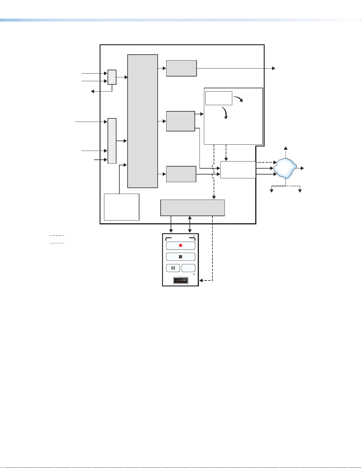
Inputs Outputs
SMP 300 Series
1: HDMI/DVI
2: HDMI/DVI
Channel
A
Frame rate
conversion
HDMI/DVI
rear panel
local output
HDMI Loopthrough
(unprocessed)
Channel
B
3: Analog
component
video (YUVp,
YUVi) or
composite video
4: HDMI/DVI
5: 3G/SDI/HD-SDI
(optional)
Background
PNG le
(internal
storage)
= Recorded le upload (if set up)
= Optional streamed output
1
Archive encoding produces:
• one composite stream for SMP 351 models
• two (dual) streams or one composite stream
for SMP 352 models and for SMP 351
models with LinkLicense.
Deinter-
lacing,
scaling,
rasterizing,
blending
Archive
encoding
Confidence
encoding
Control
+12 V
power
signals
RECORD
USB STORAGE
MARK
1
Recording
les
Internal
storage
Data /
recording
External
and
USB
/or
drive
(front or
rear port,
or RCP
101)
LAN
port
2
For automatic uploading,
set a default destination (Extron
Entwine EMP system, Extron
SCM system, Kaltura system,
Opencast system, or an FTP,
SFTP, or CIFS server location)
to which to publish recordings
(Scheduled Events > Publish
Settings).
Automatic2
upload of
recording
network
AV
Controls
panel
preview
to a
drive
TCP/IP
Network
Streamed
condence
output
Streamed
archive
output
RCP 101
Figure 3. SMP300 Series Block Diagram
File Storage
Internal storage is available for storing background image files and storing recordings to
be uploaded to a file server. Some models have 80 GB internal, solid state storage, other
models have 400 GB internal, solid state storage. You can view the total storage size for
your model in the storage information table found on the Recording Controls embedded
web page (see Storage Information in the help file) or by checking the part number
(Configuration > System Settings > Unit Identification). From the front
panel of the device, use the STATUS menu (see Status Menu on page46) and scroll
down to the Drive Space sub-menu to determine the total drive space and remaining
space.
Two USB ports (one on the front panel, one on the rear panel) provide a connection for
portable, user-provided USB drives for storing recordings. The optional RCP 101 also has a
USB port to connect a user-provided USB drive for storing recordings.
If the unit is connected to a LAN (see Add a Network Share on page87), background
image files provided by a user can be uploaded to the SMP or imported from a network
attached storage drive. To use background images in composite mode, the files must reside
in internal storage.
SMP 300 Series • Introduction 6
Page 14

Control Options
The SMP300 Series can be controlled using the following:
• Front panel menus and controls
• Simple Instruction Set (SIS) commands sent over Ethernet via the LAN connection, over
• Ethernet connection and the SMP 300 Series embedded web pages or SIS commands.
• USB mouse and keyboard ports provide for direct connection of a keyboard and
• Four digital I/O ports can be configured (using a FlexOS application) as digital inputs
• The optional Extron RCP 101 remote control panel connected through either the
Recordings
The core function of the SMP300 Series is to create recording files from connected audio
and video input sources.
Start a recording
Recordings are initiated in one of several ways:
• Unscheduled (adhoc) recordings — Require manual configuration. To use this
RS-232 via the rear panel Remote captive screw connector, or over USB via the front
panel Config port.
mouse to permit the use of an internal browser client. This allows limited web page
configuration of the network settings for the device.
to receive status from other devices like pushbutton controls and projector lifts.
Alternatively, they can be configured as digital outputs to drive LEDs or devices that
accept a TTL input signal for local device control.
keyboard or mouse port of the rear panel.
method, perform one of the following:
• Press the Record ( ) button on the front panel of the SMP300 Series or
RCP101 remote control panel
• Click the Record ( ) button in the AV Controls panel of the SMP300 Series
embedded web pages (see Start an AdHoc Recording on page58) and set
the options in the Start an Adhoc Recording window
• Tap a control button on a configured touchpanel (such a an Extron RCP 101 or
TLP Pro Series touchpanel with a custom script).
• Scheduled recordings — Start automatically at the date and time specified in a
calendar schedule. Schedules can be imported on a one-time basis, on a periodic basis
(updated on a fixed interval), or on an ongoing basis (using a compatible scheduling
server such as Opencast or Microsoft Exchange) (see System Settings on page80
for details on how to set up recording schedules).
Make a recording
The SMP300 Series creates recordings by:
• Composite Mode — Scaling and arranging the content from one or both AV input
channel A and channel B and the optional background .png file as defined by the
selected layout preset (see Troubleshooting on page88)
• Dual Mode — Scaling channel A and channel B in full screen with no background and
no metadata.
SMP 300 Series • Introduction 7
Page 15

• Encoding the content into up to three encoding streams (two encoding streams [archive
and confidence] in composite mode, 3 encoding stream [ChA archive, ChB Archive and
Confidence] in dual channel mode. See Encoder Settings and Layout Presets on
page74).
• SMP 351 models encode the content and layout into two encoding streams, archive
and confidence.
• SMP 352 models and SMP 351 models with LinkLicense encode the content and
layout into three encoder streams that include archive channel A, archive channel B,
and confidence.
• Creating a set of files — one or more .m4v or .mp4 files and other files containing
metadata, thumbnail images, and optional chapter markers. These files are stored either
within the unit (the internal, default location), or on an optional USB drive (see Encoder
Settings and Layout Presets on page74 for instructions on how to set the default
recording storage location).
The SMP300 Series creates a set of the same types of files for every recording, regardless
of how a recording is initiated. Default file names are specified within the System
Settings page (see Setting the Default Recording Media on page82 for details).
Output and share recordings
Recording files can be saved in the SMP300 Series internal memory and on an optional
connected USB drive. Recordings stored internally (not on a USB drive) can also be
automatically uploaded to a network server folder.
NOTES:
• When integrated with an Opencast and Entwine, Kaltura, or Extron SCM server,
both adhoc and scheduled recordings are automatically uploaded to the server
location defined during the scheduling setup.
• To upload recordings for other scheduling or integration methods, specify a
publishing destination during system setup (FTP, SFTP, or CIFS/Windows Net Share
server folder).
Uploading recordings to a server allows you to archive or share files with others who are
authorized to access that folder or to use tools such as Extron Streaming Content Manager
(SCM) and Entwine EMP. Streaming Content Manager checks the designated network
server locations for new recordings, packages SMP300 Series recording files with a player
application (Extron Media Player) and additional information, and automatically distributes
recording packages to event presenters via a secure web page interface.
Entwine EMP is a tightly-integrated end-to-end software solution that facilitates the capture,
management, and playback of media files from meetings, lectures, and other live events.
Current, previously recorded, or archived media files can be added to Entwine EMP, making
everything accessible from a single point. Entwine EMP ensures recordings with metadata
are packaged for playback within the player environment.
Features
• Process two high resolution AV signals from up to five available inputs — Sizes
and positions two AV source signals in layouts that maximize the viewing experience.
• Stream and record simultaneously — Use the SMP300 Series to document
presentations and extend live streaming to overflow rooms or media servers. AV and IT
staff can also view streaming in low resolution for support functions.
SMP 300 Series • Introduction 8
Page 16

• High quality scaling with flexible two-window management (For composite mode
only) — Display one or two high resolution sources in various window arrangements,
including picture-in-picture and picture-by-picture arrangements for optimal
interpretation.
• Record to internal and USB storage simultaneously (For composite mode only)
— Enable dual recording from the embedded web pages, and the SMP 300 Series
can save a copy of the recording to the internal SSD drive and an identical copy to the
selected USB storage drive.
• Produces MP4 media files that are compatible with virtually any media player
— Use recordings produced by the SMP300 Series directly with any software media
player, computer, or mobile device.
• Flexible I/O ports for advanced AV system management — Install Extron FlexOS
applications onto the SMP300 Series that interface with control ports and automate
system operation.
• License-free operation contributes to a low cost of ownership — With no
licensing or support fees, the SMP300 Series is a cost effective solution for AV
streaming and recording.
• Save recordings to internal solid state drive, external USB storage, or a defined
network storage directory — Recordings can be saved to pre-defined locations most
convenient to users.
• Stream concurrently at three resolutions and bit rates — High resolutions and
high bit rates deliver superior quality images for overflow applications and lower bit rates
and resolutions are more efficient for streaming distribution and confidence viewing
applications.
• SMP 351 models have two encoding streams, archive and confidence.
• SMP 352 models and SMP 351 models with LinkLicense have three resolutions
and bit rates, archive channel A, archive channel B, and confidence.
• Chapter and event marking with thumbnails viewable in Extron Media Player —
Chapters or events can be marked, and JPEG image thumbnails are produced that
promote efficient searching and scanning from the Extron Media Player (EMP).
• Record at 480p, 720p, 1080p, 1024x768, 1280x1024, or custom resolution —
Use standard video resolutions or computer resolutions and user-defined custom rates
based on content or viewing requirements.
• Stream at resolutions from 512x288 to 1080p/30 — High resolutions deliver
superior quality images for overflow applications and lower resolutions are more efficient
for streaming distribution and confidence viewing applications.
• HDMI, component, composite, and optional 3G-SDI input — Provides
compatibility with common AV signal formats at resolutions up to 1920x1200 including
1080p/60. The SMP351 3G-SDI and SMP 352 3G-SDI models offers an additional
3G-SDI input connection.
• Easy to configure and operate from the front panel or external control system
— Ensures that presentations will be streamed and recorded and valuable information
will be documented and repurposed.
• Window layout presets simplify control — Sixteen standard and customized source
layouts are available to be recalled quickly from the front panel or an external control
system in composite mode.
• Internal Solid State Storage — Save recorded data to reliable, internal storage,
before transferring it to external destinations. For the 400 GB version, up to eighty hours
of material can be saved to internal storage using archive quality media encoded at
10Mbps.
SMP 300 Series • Introduction 9
Page 17

• Define specific storage destinations for recorded data — Configure the SMP300
Series to save recordings to specific storage directories based on the user environment
or application requirements.
• Manage AV recordings using Extron Streaming Content Manager — SCM
prepares recording packages that offer an enhanced playback experience from
the Extron Media Player. SCM manages users and groups, and transfers recording
packages to a rights-managed storage directory.
• Manage AV recordings using Entwine EMP (Enterprise Media Platform) — Ensures
recordings with metadata are packaged for playback within the player environment.
• HDCP-compliant input and output signal management — Encrypted signals
can be viewed on compliant displays connected to the SMP300 Series loop through,
but cannot be streamed or recorded. A green signal is presented at non-compliant
destinations.
• HDMI output with audio — Presents a preview of the blended source layout, which
is only available in composite mode, that is recorded or streamed with mixed, HDMIembedded stereo audio. Mixed analog stereo audio is also available.
• HDMI-embedded stereo audio or analog stereo input and output signal support
— Digital and analog audio signals are supported on the input channels and the output
channel.
• Audio mixing and DSP functionality — Produces a quality audio experience without
requiring the use of external mixing and DSP equipment.
• DSP functions enabled by LinkLicense — Includes advanced audio DSP features,
such as level control, filtering, and dynamics, and streaming presets that increase
functionality and provide a simplified workflow
• Directly compatible with Opencast Server — Integrate scheduling and publishing of
recorded media directly to the Opencast open source content management system.
• Directly compatible with Kaltura — Integrate publishing of recorded media directly
to Kaltura Management Console.
• Compatible with third party content management systems — Manually upload
recordings to systems such as iTunes-U, Blackboard LMS, SharePoint, CaptionSync,
YouTube, Moodle, and RSS feed.
• Schedule recordings using iCalendar — Configure recording schedules on the
SMP300 Series by importing iCalendar files manually or automatically.
• Uploadable Extron FlexOS applications — Upload applications that use the four
digital I/O ports to control and manage devices used in the AV presentation environment
for recording or streaming applications.
• RS-232, Ethernet, and digital I/O control ports — Interface with control systems,
sensors, or external devices used in the AV presentation environment.
• Supports source resolutions up to 1920x1200, including HDTV 1080p/60 — The
SMP300 Series supports a wide range of input resolutions, from standard definition up
to the resolutions commonly used for computer video and HDTV.
• Standards-based H.264/MPEG-4 AVC video compression — The SMP300 Series
supports use of the Baseline, Main, or High Profiles at Levels 4.x, or 3.x providing the
ability to optimize video coding for use with various types of applications and decoding
devices.
• Channel A buffered input loop-through — Channel A input connectors include a
buffered loop-through, for easy integration into new or legacy systems without the need
for additional AV equipment such as distribution amplifiers.
SMP 300 Series • Introduction 10
Page 18

• Auto-Image setup — When activated, the unit automatically analyzes the incoming
video signal and then automatically adjusts sizing, centering, and filtering to optimize
image quality. This can save time and effort in fine tuning displayed images.
• Recording layout presets simplify control (Composite mode only)— The SMP300
Series provides 16 standard or customizable presets that specify the size and
positioning of AV sources and metadata, simplifying management and selection of
layouts from the front panel or an external control system.
• Encoding presets for quick recall of specific compression settings — The
SMP300 Series provides 32 standard or customizable presets for saving specific
encoding settings such as H.264 profile, resolution, GOP (group of pictures) length, and
bit rate session management configurations. Users can quickly switch between these
presets to support different applications.
• Push and pull streaming session management — The flexibility to apply push and
pull streaming session management makes the SMP300 Series compatible with a
variety of H.264 devices and streaming applications.
• Pull streaming transport protocols — RTP, RTSP interleaved, and HTTP tunneled
streaming transport protocols may be applied, based on various network conditions or
to aid in firewall navigation.
• Push streaming transport protocols — Native RTP and MPEG-2 Transport
Streams (TS) may be applied in unicast or multicast streaming applications. TS may be
transported using UDP or RTP based on network conditions.
• RTMP streaming protocol supports popular third party hosting services —
Supports RTMP push streaming with stream name or key, and user authentication for
services like YouTube Live, Wowza Streaming Cloud, Facebook Live, Ustream, and
more.
• Session Announcement Protocol (SAP) and Session Description Protocol (SDP)
— SAP and SDP protocols simplify identification of AV source streams in unicast or
multicast push streaming applications.
• Adjustable recording and streaming bit rates — Select video bit rates from
200Kbps to 10 Mbps for video and audio bit rates from 80 Kbps to 320 Kbps based
on the viewing application, storage, streaming or network conditions.
• Clean switching — Switching has a clean transition between sources. Distractions
such as visual jumps, glitches, and distortion commonly experienced when switching
between computer and video sources will not be experienced when using the SMP300
Series.
• Recording metadata — Metadata can be assigned to make indexing and searching of
recordings simple including: Title, Presenter, Subject, Description, Publisher, Contributor,
and Date.
• Metadata text overlay (Composite mode only) — Data concerning the recording
can be presented and clearly identified on recording layouts with AV sources and a
background image.
• Uploadable background image files (Composite mode only) — Upload PNG image
files at resolutions up to 1920x1080 to identify organizational or event information.
Background image can be applied in composite mode only.
• On-screen display information (Composite mode only) — Present device information
and status on source images to aid in troubleshooting and fault finding activities.
• On-screen display video time reference (Composite mode only) — Text displaying a
time reference (HH:MM:SS Format) can be presented within the onscreen display in the
top left corner of the output signal.
SMP 300 Series • Introduction 11
Page 19

• System workflow alarms — Notify monitoring systems or support staff if disk space
is low, encrypted signals are detected, AV signal errors occur, or other error conditions
exist.
• Alarm reporting — Automate communication with monitoring systems or support staff
using e-mail via Simple Mail Transfer Protocol.
• Includes LockIt HDMI cable lacing brackets.
• Rack-mountable 1U, full rack width metal enclosure.
• Internal universal power supply — The 100-240 VAC, 50-60 Hz, international power
supply provides worldwide power compatibility.
SMP 300 Series • Introduction 12
Page 20

Installation
100-240V 0.8A MAX
5
USB STORAG
3
/
5
3G/HD/S
O
R
L
R
U
U
S
C
S
C
B
OUTPUTS
S
s
2
G
MOUSE /
K
D
LM
PQNO
This section provides information on:
• Mounting the SMP300 Series
• Rear Panel Overview
• SMP300 Series Rear Panel Reset
Mounting the SMP300 Series
The SMP300 Series models are housed in a 1U high, full rack width metal enclosure that
can sit on a table with the provided rubber feet or can be mounted using the attached
rack mounts. Select a suitable mounting location (see Mounting the SMP300 Series on
page126), then choose an appropriate mounting option. Before connecting the SMP300
Series, turn off all devices that are to be connected.
Make all external device connections to the SMP models before applying power.
Rear Panel Overview
ABCDEFGH
100-240V 0.8A MAX
50-60 Hz
0-60 Hz
USB STORAGE
MOUSE /
KEYBOARD
EYBOAR
1
DIGITAL I/O
REMOTE
E
1234G
Tx Rx
RS-232
G
E
2
H A
-
T
INPUTS-CH A
NP
Figure 4. SMP300 Series Rear Panel (SMP351 3G-SDI shown)
100-240 VAC IEC connector for power input
A
USB type A receptacle for external storage device
B
(2) USB type A receptacles for mouse and keyboard, or
C
remote control RCP 101
3.5 mm, 5-pole captive screw connector for digital I/O
D
3.5 mm, 3-pole captive screw connector for Simple
E
Instruction Set (SIS™) control over RS-232
HDMI inputs 1 and 2
F
3.5 mm, 5-pole captive screw connector for channel A
G
analog stereo audio input
HDMI
LOOP THRU
1
2
P THR
J
K
L
M
N
O
P
JK
I
RESET
SMP 300 Series
MP 300 Serie
LAN
AUDIO
AUDI
LR
LR
INPUTS-CH B
3
H
-
NPUT
B-Y
-Y
R-Y VID
-
5
3G/HD/SDI
DI
4
AUDIOLR
HDMI
/Y
Y
OUTPUTS
AUDIOLR
HDMI
(Optional input 5) 3G/HD/SDI input card
(SMP 351 3G-SDI and SMP 352 3G-SDI only)
3.5 mm, 5-pole captive screw connector for channel B
analog stereo audio input
HDMI loop thru from input 1 or 2
3.5 mm, 5-pole captive screw connector for channel A
analog stereo audio loop output
HDMI preview output
3.5 mm, 5-pole captive screw connector for analog stereo
audio output
Reset button and LED
3 BNC connectors for component or composite video
H
RJ-45 Ethernet connector for LAN connection
Q
input 3
HDMI input 4
I
SMP 300 Series • Installation 13
Page 21

Power Connection
100-240 VAC power input – Connect the provided IEC cord. Verify the front panel
A
buttons and LCD illuminate (see Front Panel Features on page19).
Control System and External Device Connections
The SMP300 Series can be configured and controlled from the Remote RS-232 port (see
figure 4, E on the previous page) or the front panel USB mini-B Config port (see
figure 8, B page19) using SIS commands and DataViewer via Telnet port 23. A
standard web browser can be used for control and configuration from the LAN port.
Because the LAN port must be connected for streaming output, Extron recommends using
it for configuration, remote control, and firmware upgrades.
USB storage device – You can attach an optional external USB storage device to the
B
front or rear USB ports to save recorded files. The storage device can be any standard
external hard drive or USB flash drive formatted with a compatible file system.
NOTE: The SMP300 Series can detect and record to USB storage devices using
FAT32, VFAT long file name extensions, EXT2, EXT3, EXT4 file systems, or NTFSformatted storage volumes.
USB keyboard and mouse, or RCP 101 – Connect a keyboard and mouse to the
C
two USB typeA ports. With a keyboard and mouse connected, the user can toggle
<CTL+ALT+S> the HDMI output (see figure 8 on page19) between the standard
preview output and the internal browser view.
Digital I/O – Connect to the four 3.5 mm, 5-pole captive screw connectors to provide
D
user-defined digital inputs or outputs (see About the FlexOS App - Digital I/O
Configurator on page94).
Remote — To control the SMP300 Series using SIS commands over RS-232, connect
E
the host RS-232 cable to the rear panel (see figure 13 on page24) with a 3-pole
captive screw connector for bi-directional (±5V) serial host control. The default protocol
for this port is as follows:
• 9600 baud
• no parity
• 8 data bits
• 1 stop bit
• no flow control (handshaking).
Reset button and LED — Press the reset button to reset the SMP300 Series. There
P
are several reset modes to return to user-defined configuration settings or to return
all settings back to factory defaults. The LED indicates the desired reset mode, and
provides the reset status during the reset operation (see SMP300 Series Rear Panel
Reset starting on page17).
RJ-45 Ethernet connector (LAN) — Use a standard Ethernet cable to connect to a
Q
network. The default network settings are:
IP Address:
Subnet Mask:
Default Gateway:
DHCP: OFF
NOTE: To connect the SMP300 Series directly to a computer Ethernet port, use a
crossover Ethernet cable (Connection Options on page95).
192.168.254.254
255.255.0.0
0.0.0.0
SMP 300 Series • Installation 14
Page 22

Input Connections
Do not tin the wires!
Slee
Do not tin the wires!
Sleeve(s)
The audio and video inputs are grouped into channel A and channel B.
• Channel A analog audio input can be selected for video inputs 1 or 2 (F).
• Channel B analog audio can be selected for video inputs 3 (H), 4 (I), or 5 (J).
HDMI input (1 and 2) – Connect an HDMI (or DVI with suitable adapter) source device
F
to input 1 and input 2.
NOTE: Channel A (inputs 1 and 2) is optimized for full range sources such as PCs.
Channel A analog audio input – Connect a balanced or unbalanced stereo line level
G
audio device to this 5-pole, 3.5 mm captive screw connector. Channel A audio can be
selected for output with HDMI inputs 1 and 2 instead of the embedded audio. Wire the
connector as shown in figure 5.
When using a video source with adjustable quantization range on these inputs,
select "Full Range" for the most accurate video reproduction.
Tip
Ring
ve(s)
Tip
Ring
Left
Right
Tip
Sleeve
Tip
Sleeve
Left
Right
Unbalanced Stereo InputBalanced Stereo Input
(high impedance)(high impedance)
Figure 5. Audio Input Captive Screw Connector Wiring
Analog video input 3 – Connect component video to the three BNC connectors (B-Y,
H
R-Y, VID/Y). Connect a composite video signal to the VID/Y BNC connector.
HDMI input 4 – Connect an HDMI (or DVI with suitable adapter) source device to
I
input4.
Serial digital video input 5 (SMP 351 3G-SDI and SMP 352 3G-SDI only) –
J
Connect a 3G/HD/SDI video signal to this BNC connector.
Channel B analog and 3G-SDI audio input – Connect a balanced or unbalanced
K
stereo line level audio device to this 5-pole, 3.5mm captive screw connector. Channel
B audio can be selected from either the HDMI embedded audio, ChB analog audio, or
the audio can be set to Off. Wire the connector as shown in figure 5.
Output Connections
HDMI loop-thru output – Connect an HDMI (or DVI with suitable adapter) display
L
device to the HDMI Loop Thru connector to view the selected input 1 or input 2.
Audio loop output – Connect a balanced or unbalanced stereo line level audio device
M
to this 5-pole, 3.5 mm captive screw connector (see figure 4, M on page13). Wire
the connector as shown in figure 5. Audio is always from audio input G.
ATTENTION:
• For unbalanced audio, connect the sleeves to the ground contact. DO NOT
connect the sleeves to the negative (–) contacts.
• Pour l’audio asymétrique connectez les manchons au contact au sol. Ne PAS
connecter les manchons aux contacts négatifs (–).
Tip
Ring
Tip
Ring
Left
Right
Balanced Audio Output Unbalanced Audio Output
Tip
NO Ground Here
Sleeve(s)
Tip
NO Ground Here
Figure 6. Audio Output Captive Screw Connector Wiring
SMP 300 Series • Installation 15
Left
Right
Page 23

ATTENTION:
• The length of the exposed wires in the stripping process is important. The ideal
length is 3/16 inch (5 mm). If longer, the exposed wires may touch, causing a
short circuit between them. If shorter, the wires can be easily pulled out even if
tightly fastened by the captive screws.
• La longueur des câbles exposés est importante lorsque l’on entreprend de les
dénuder. La longueur idéale est de 5mm (3/16inches). S’ils sont un peu plus
longs, les câbles exposés pourraient se toucher et provoquer un court circuit.
S’ils sont un peu plus courts, ils pourraient sortir, même s’ils sont attachés par
les vis captives.
• Do not tin the wires. Tinned wires are not as secure in the captive screw
terminals and could pull out.
• Ne pas étamer les câbles. Les câbles étamés ne sont pas aussi bien fixés dans
les terminaisons des à vis captives et pourraient sortir.
HDMI preview output – Connect an HDMI (or DVI with suitable adapter) display
N
device to this HDMI output connector. Using an attached USB keyboard and mouse,
the Preview Output can be switched between a preview of the recorded content and an
internal browser client.
Analog Audio output – Connect a balanced or unbalanced stereo line level audio
O
device to this 5-pole 3.5 mm captive screw connector (see figure 6 on the previous
page) for select audio output. Wire the connector as shown in figure 6.
The audio output depends both on the input selection and if the embedded audio or
analog audio is selected for that input (see Audio Select on page40). Audio output
is selected from channel A, from channel B, or a mix of both channel A and channel B.
For SMP 352 and SMP 351 with LinkLicense, when dual mono is enabled, audio output
is selected from channel B dual mono or a mix of both channel A and channel B dual
mono.
NOTE: The default audio channel is channel A and channel B. When dual mode is
enabled, the default output is channel A and channel B dual mono.
SMP 300 Series • Installation 16
Page 24

SMP300 Series Rear Panel Reset
The Reset button on the rear panel of the SMP300 Series (see figure 4 on page13)
returns the SMP300 Series to various modes of operation. There are three unit reset modes
(numbered 1, 4, and 5) that are initiated from the rear panel reset button. To select different
reset modes, use a pointed stylus or small screwdriver to press and hold the Reset button
while the SMP300 Series is powered or press and hold the Reset button while applying
power to the SMP300 Series.
NOTES:
• The reset modes listed in the table on the next page close all open IP and Telnet
connections and all sockets.
• Each reset mode is a separate reset (not a continuation from mode 1 to mode 5).
• Reset modes 2 and 3 are not available for the SMP300 Series.
• The SMP300 Series can also be reset using the Web-based User Interface (see
System Resets on page93).
• For information on resetting the SMP300 Series using SIS commands (see Resets
on page104).
• Further details comparing the reset modes and detailing affected configuration
settings and user content are available in the Input Connections on page15.
ATTENTION:
• Review the reset modes carefully. Some reset modes delete all user loaded content
and revert the device to default configuration.
• Étudier de près les différents modes de réinitialisation. Certains modes de
réinitialisation suppriment la totalité du contenu chargé de l’utilisateur et remettent
l’appareil en mode de configuration par défaut.
See the following for a summary of the reset modes.
Mode 1
Press and hold
the Reset button.
Mode 4
Press and hold
for 6 seconds.
Mode 5
Press and hold
for 9 seconds.
RESET RESET
RESET RESET
RESET
Apply power
to the SMP 300 Series.
Reset LED flashes twice.
Reset LED flashes three
times.
RESET
Release, then immediately
press and release again.
Reset LED flashes, then goes off.
RESET
Release, then immediately
press and release again.
Reset LED flashes, then goes off.
RESET
Release Reset button.
Figure 7. Resetting the SMP300 Series
SMP 300 Series • Installation 17
Page 25

SMP 300 Series Reset Modes
Mode Activation Result Purpose and Notes
1 Hold in the recessed rear
panel Reset button while
applying power to the unit.
The SMP300 Series reverts to the
factory default firmware for a single
power cycle.
Use mode 1 to revert to
the factory default firmware
for a single power cycle if
incompatibility issues arise
with user-loaded firmware.
All user files and settings are
maintained.
Factory Firmware
NOTE: Do not operate with the default firmware loaded by a
mode1 reset. Use it only to load the most current firmware to
the device.
4
Hold in the Reset button
until the Reset LED blinks
twice (once at 3 seconds,
again at 6 seconds). Then,
release and press the
Reset button again within 1
second*.
• Sets port mapping back to factory
default.
• Sets the IP address back to
factory default (192.168.254.254).
• Sets the subnet mask address
back to the factory default
(255.255.0.0).
Mode 4 is used to set
IP address information using
ARP and the MAC address.
"Resetting IP Settings"
appears on a connected
display.
• Sets the gateway IP address to
the factory default (0.0.0.0).
• Turns DHCP off.
Reset All IP Settings
• The Reset LED on the rear panel
of the unit flashes four times in
succession.
5
Hold in the Reset button
until the Reset LED blinks
three times (once at 3
seconds, again at 6 seconds,
again at 9 seconds). Then,
release and press the
Reset button again within 1
second*.
Reset to Factory Defaults
Performs a complete reset to factory
defaults (except the firmware).
• Does everything mode 4 does.
• Clears port configurations.
• Resets all IP options.
Clears all user settings.
• Clears all files from the unit.
• The Reset LED on the rear panel
of the unit flashes four times in
succession.
Mode 5 is useful to start over
with default configuration and
uploading, and also to replace
events.
"Resetting SMP300 Series"
appears on a connected
display.
Mode 5 is equivalent to
SIS command ZQQQ (see
Absolute reset SIS command
page104).
NOTE: * = For modes 4 and 5, nothing happens if the momentary press does not occur within 1 second.
SMP 300 Series • Installation 18
Page 26

Front Panel Operation
This section of the manual discusses the operation of the SMP300 Series from the front
panel.
Topics covered include:
• Front Panel Features
• Layout Presets (For Composite Mode Only)
• SMP300 Series Power Up Procedure
• Front Panel Menu Operation
• Front Panel Lockout (Executive Modes)
• Alarms
Front Panel Features
BBCCDDEEFFGGHHIIJJAA
Extron
USB STORAGE
CHANNEL A
CHANNEL B
CONFIG
2
1
4
3
5
AUDIO
LAYOUT
LR
PRESET
SWAPSWAP NEXT
MENU
NEXTMARK
ADJUST
I/O
1
2
3
4
SMP 300 Series
PRESENTATION CAPTURE RECORDER
Figure 8. SMP300 Series Front Panel
Type A USB connector and activity LED for
A
external storage
USB mini B connector for configuration
B
Input buttons for source selection
C
Record controls with LED indicators
D
Audio level indicators
E
USB storage port and activity LED – Connect a USB compatible media device to
A
this port. The green LED blinks during both reading and writing of data. The storage
device can be any standard external hard drive or USB flash drive formatted with a
compatible file system.
NOTE: The SMP300 Series can detect and record to USB storage devices using
FAT32, VFAT long file name extensions, EXT2, EXT3, EXT4 file systems, or NTFSformatted storage volumes.
ATTENTION:
• Disconnecting a USB device while recording to it may result in corrupt or lost
data.
• Déconnecter un périphérique USB alors qu’un enregistrement y est effectué,
peut engendrer une altération ou une perte de données.
Layout Preset and Swap buttons
F
Menu display
G
Menu Navigation buttons (MENU and NEXT)
H
Adjust knobs (left [ and right {)
I
I/O display LEDs
J
SMP 300 Series • Front Panel Operations 19
Page 27

Config port — Connect a control device to this port with a USB mini-B cable (not
B
supplied). Use this port to send SIS commands to the SMP300 Series for device
configuration and control (see Remote Communication and Control starting on
page95).
Input selection — Press these buttons to select inputs associated with the rear panel
C
input connections.
• Channel A – Press the corresponding button to select HDMI input 1 or 2. If analog
audio (instead of embedded audio) is selected for an input, Channel A analog audio
is output with the video.
• Channel B – Press the corresponding button to select composite/component
input3, HDMI input 4, and (optional) SDI input 5. If analog audio is selected for
input 4, Channel B analog audio is output with the selected video input.
The currently selected Channel A input button and currently selected Channel B input
button light solid amber.
NOTE: Input 5 lights only when the optional SDI input card is installed and the input
is selected.
Record controls with LED indicators – Press the Record, Stop, Pause, and
D
Mark buttons to perform the operation. The buttons light to indicate the current state of
record operation.
• Record – Press to record the selected inputs. The record button lights solid
red during active recording.
• Stop – Press to stop the active recording. When pressed during a recording,
the stop button blinks green while the recorded file is being finalized, then lights
solid green when the file is finalized.
• Pause – Press to pause recording. When pressed, the Pause button blinks
green to indicate recording is paused. Press Record or press Pause again to
resume recording, or press Stop to halt the recording.
• Mark – Press
MARK
to place a chapter marker in the recorded file. When pressed
during recording, the button illuminates green momentarily to indicate a chapter
marker is inserted. The button also illuminates when JPEG thumbnails are
automatically created at a fixed interval (default: 1 minute).
Audio level indicators – Two stacks of eight green LEDs track the audio level of the
E
left and right audio channels from -60 dBFS (one LED) to 0 dBFS (eight LEDs). The
LEDs indicate both signal presence and active input signal levels.
• Input Configuration Mode – When input gain is adjusted, the meters display the
currently selected input left and right channel audio levels to assist setting audio
gain (see Audio level starting on page41).
• Normal Mode – The meters display the left and right encoder input levels
measured after all audio input adjustments are applied and audio sources are
blended/merged (if applicable).
Layout Preset (For composite mode only) and Swap – Press LAYOUT PRESET to
F
select one of the 16 capture presets (see Layout Presets (For Composite Mode
Only) on the next page. The button illuminates green. Use the ADJUST knobs (I) to
select the desired output layout. Press NEXT (H) to activate it.
Press SWAP to switch Channel A and B inputs between the two layout windows. The
button illuminates green for 1 second to indicate the input swap.
SMP 300 Series • Front Panel Operations 20
Page 28
Menu display – Displays configuration menus and status information. Use the MENU
SMP 300 Series
PRESENTATION CAPTURE RECORDER
I/O
1
2
3
4
HIIJJAA
G
and NEXT buttons (H) and ADJUST knobs (I) to navigate the menu. During normal
operation, a default display cycle is presented (see SMP300 Series Power Up
Procedure on page23). If there is an active alarm (see Alarms on page47), it is
listed instead.
Menu Navigation (MENU and NEXT) – Lights amber (unless menu lockout is
H
enabled). Press to access and navigate the configuration and control menus and
submenus.
NOTE: The menu button blinks red when there is an active alarm (see Alarms on
page47).
MENU — Use this button to enter and move through the main menu system.
NEXT — Use this button to step through the submenus of the selected menu.
Adjust knobs (left [ and right {) – Rotate these controls to scroll through menus
I
and to make adjustments within a menu or submenu.
NOTE: The buttons and controls on the SMP300 Series can be locked so that
configuration using the front panel is not possible (see Front Panel Lockout
(Executive Modes) on page47).
I/O display – A stack of four green LEDs that correspond to the four digital I/O
J
connections on the rear panel (see figure 4 on page13). Each LED indicates the
on or off status of the corresponding ports which can be configured as digital input or
digital output (see About the FlexOS App - Digital I/O Configurator on page94).
Layout Presets (For Composite Mode Only)
Layout presets define which inputs are selected and where they are placed on the output
screen. There are 12 preconfigured and 4 user presets for custom layout configurations.
FGGH
LAYOUT
PRESET
SWAPSWAP NEXT
Figure 9. Front Panel Layout Preset and Swap (F)
The two input channels, A and B, are determined by direct selection from the front panel.
To select 1 of the 12 preconfigured layout presets:
1. Select input 1 or 2 for channel A and input 3, 4, or 5 for channel B (see Front Panel
Features on page19).
2. Press LAYOUT PRESET (F) to open the menu on the front panel display (G).
3. Use either ADJUST knob (I) to cycle through the presets. When the desired layout
name appears on the output display, stop.
MENU
NEXT
ADJUST
SMP 300 Series • Front Panel Operations 21
Page 29

PBP Upper Left <1>
PbP 25%, main window 75%
PBP Mid Right <4>
Side by Side <7>
Fullscreen B <10>
Ch. B
16:9
METADATA
METADATA
PBP Upper Right <2>
PbP 25%, main window 75%
Ch. A
16:9
PBP Mid Left <3>
PbP 25%, main window 75%
Ch. B
16:9
METADATA
METADATA
Ch. A
16:9
Ch. A
16:9
Ch. B
16:9
METADATA
METADATA
PbP 25%, main window 75%
Ch. A
16:9
PIP Upper Left <5>
PiP 25%, main window 100%
Ch. B
16:9
Ch. A
16:9
PIP Upper Right <6>
PiP 25%, main window 100%
Ch. A
16:9
Ch. B
16:9
METADATA
METADATA
Ch. B
16:9
Windows horizontally centered
METADATA,
MORE METADATA
METADATA,
MORE METADATA
Ch. A
16:9
Ch. B
16:9
Ch. B
16:9
Ch. A
16:9
Side by Side (1) <8>
Windows horizontally centered
Ch. A
16:9
Fullscreen A <9>
main window 100%
main window 100%
Ch. B
16:9
CH A Center <11>
main window 75%, centered in screen
Ch. A
16:9
METADATA, MORE METADATA
CH B Center <12>
main window 75%, centered in screen
Ch. B
16:9
METADATA, MORE METADATA
Figure 10. Layout Presets
NOTE: PBP = Picture Beside Picture
PIP = Picture In Picture
4. Press NEXT (H) to select the layout.
5. If desired, press SWAP to reverse the screen position of the A and B input selections.
To store a custom layout configuration:
1. Select the layout from the above configurations closest to your requirements.
2. Change the window size and centering adjustments for each input to modify the layout
as needed (see Picture Control Menu on page28),
3. Press and hold LAYOUT PRESET for 3 seconds to enter the save layout menu.
4. User either ADJUST knob to select the desired preset location to store the new layout.
5. Press NEXT to save the new layout.
NOTE: In order to preserve the aspect ratios of the windows, some layouts can
have slightly different spacing at lower resolutions. It is recommended to save
custom layouts at the resolution at which they will be recalled.
SMP 300 Series • Front Panel Operations 22
Page 30

SMP300 Series Power Up Procedure
NOTE: Before powering the SMP300 Series, ensure that all necessary devices are
connected properly. Devices do not need to be powered.
Connect the power cord to a 100 to 240 VAC supply (see Power Connection on
page14). The unit undergoes self testing during the boot sequence (see figure 11
and figure 12 below). After the sequence is complete (and when the device is not being
configured or has an active alarm), the default display cycle is on the LCD display.
2
Power
On
EXTRON
ELECTRONICS
LOADING
FIRMWARE
Figure 11. Boot Sequence and Default Display Cycle for Composite Mode
~4
sec.
EXTRON
sec.
SMP 35x FW V1.06
30
sec.
SMP 35x
INITIALIZING
45
sec.
Default Display Cycle
2
In 1 1024x768@60
In 3 720p@60
2 sec.
TIME REMAIN
HH:MM:SS
sec.
2
sec.
ARCHIVE 5.0 MB
1280x720@30 fps
2 sec.
TIME RECORD
HH:MM:SS
Power
On
EXTRON
ELECTRONICS
LOADING
FIRMWARE
2
sec.
~4
sec.
30
sec.
NOTE: The information shown in the default display cycle differs
EXTRON
SMP 35x FW V1.06
SMP 352
INITIALIZING
45
sec.
In 1 1024x768@60
In 3 720p@60
2 sec.
TIME REMAIN
HH:MM:SS
Default Display Cycle
2
sec.
CHA 5.0 MB
1280x720@30 fps
2
sec.
2 sec.
TIME RECORD
HH:MM:SS
2 sec.
CHB 5.0 MB
1280x720@30 fps
2 sec.
depending on the active input and the type of video signal.
Time Record displays only during a recording.
Time Remain displays the remaining time in the event and the
estimated recording time available during an unscheduled
recording.
Figure 12. Boot Sequence and Default Display Cycle for Dual Channel Mode
The default display cycle varies depending on the input video signal and output stream
selection. It shows the selected inputs and their resolutions, stream bit rate, and output
resolution. During recording, the current length of the recording and time remaining are
added to the default cycle.
SMP 300 Series • Front Panel Operations 23
Page 31

Front Panel Menu Operation
SMP 300 Series
PRESENTATION CAPTURE RECORDER
I/O
1
2
3
4
HIIJJAA
Configuration and adjustments can be performed
using the embedded Web pages (see Overview of
the Web-Based User Interface on page50),
the SIS commands (see Remote Communication
and Control starting on page95), or using the
front panel controls and the menus displayed on
the LCD screen (see figure 8, G on page19).
These menus are used primarily during the initial set up.
Menu Navigation
Menu display — Displays the configuration menus on a 16x2 LCD display.
G
MENU button — Press MENU to activate menus and cycle through the main menus.
H
NEXT button — Press NEXT to move between the submenus of the selected main
H
menu.
ADJUST ([,{) knobs — In configuration mode, rotate the left ([) control and right ({)
I
control to scroll through submenu options and to make configuration selections (see the
flowcharts in this chapter for details).
Menu Overview
After start-up, when no adjustments are actively being made, the Default Display Cycle (see
figure 13 and figure 14 on page24) runs on the LCD (see figure 8, G on page19).
The screen progressively cycles through the input and output format information, showing
the number and video format of the active input and the current output resolution.
GH
MENU
NEXT
NEXT
ADJUST
NOTE: If a signal is not present on the currently selected input, NOT DETECTED
appears in place of the input type. For example, IN#4 NOT DETECTED.
If there is an active recording, TIME RECORD displays the current length of the recording.
TIME REMAIN shows the time remaining for an active scheduled recording.
Default Display Cycle
2
In#1 1024x768@60
In#3 720p@60
2 sec.
TIME REMAIN
HH:MM:SS
sec.
ARCHIVE 5.0 MB
1280x720@30 fps
2
sec.
TIME RECORD
HH:MM:SS
2 sec.
Figure 13. Default Display Cycle for Composite Mode
Default Display Cycle
2
In 1 1024x768@60
In 3 720p@60
2 sec.
TIME REMAIN
HH:MM:SS
sec.
CHA 5.0 MB
1280x720@30 fps
2
sec.
TIME RECORD
2 sec.
HH:MM:SS
2 sec.
CHB 5.0 MB
1280x720@30 fps
2 sec.
Figure 14. Default Display Cycle for Dual Channel Mode
SMP 300 Series • Front Panel Operations 24
Page 32

Press the MENU button once to bring up the first main (top level) menu, as shown below.
(For Composite
Each successive MENU button press cycles to the next main menu.
NOTE: From any menu or submenu, after 30 seconds of inactivity, the SMP300 Series
times-out to the default display cycle.
Menu Menu Menu
PRESETS
Next Next
(to submenus) (to submenus) (to submenus) (to submenus)
EXIT MENU?
PRESS NEXT
Menu Menu Menu
PICTURE
CONTROL
Menu
STATUS
Next
(to submenus) (to submenus) (to submenus) (to submenus)
RECORD/STREAM
CONFIGURATION
Next
Menu Menu
VIEW COMM
SETTINGS
Next
MenuMenu
+
Input 5
for Edit Menu
INPUT
CONFIGURATION
ADVANCED
CONFIGURATION
Figure 15. Top Level Menus
The flowchart above provides an overview of the menu system.
The top level menus are displayed one at a time, in order, on the LCD panel by pressing the
MENU front panel button.
To return to the default cycle from a top level menu or submenu, press MENU repeatedly until
EXIT MENU? appears, then press NEXT. Alternatively, the menu times out after 30seconds
of inactivity and returns to the default cycle.
Press NEXT when a menu displays to access its submenu. Within the submenu, press
MENU to exit the submenu and return to the currently active menu or press NEXT to move to
the next submenu.
Submenu details with configuration and options for each setting are on the following pages.
A complete schematic of the menus and submenus is in the reference section (see Front
Panel Menu Diagrams starting on page149).
NextNextNext Next
Next
MenuMenu
BACKGROUND
RECALL
NextNext
Mode Only)
Presets Menu
The presets menu allows the user to save or recall encoder and user presets.
From the default menu, press MENU to cycle to the Presets menu.
Press NEXT to enter the submenus.
Press NEXT to advance to the relevant submenu: Recall or Save.
Within the submenu, use the ADJUST controls to select the preset, then press NEXT to
recall or save the selection.
Press MENU to exit the submenu.
SMP 300 Series • Front Panel Operations 25
Page 33

PRESETS
Next
Menu
PRESETS
Next
Menu
ARCHIVE ENCODER
RECALL
<N/A>
Rotate either to
select a preset to recall.
Next
ARCHIVE ENCODER
SAVE
<N/A>
Rotate either to select
a preset # to save
current settings to.
Next
IN<1> USER RECALL
<N/A>
Rotate [ to select an
input.
Rotate { to select a preset.
Next
IN<1> USER SAVE
<N/A>
Rotate [ to select an
input.
Rotate { to select a preset.
Next
Figure 16. Presets Menu in Composite
Mode
CHA ARCHIVE ENCODER
RECALL
<N/A>
Rotate horizontal knob to select
encoder. Rotate vertical knob to
select a preset to recall.
Next
CHA ARCHIVE ENCODER
SAVE
<N/A>
Rotate horizontal knob to select
encoder. Rotate vertical knob to
select a preset to recall.
Next
IN<1> USER RECALL
<N/A>
Rotate [ to select an
input.
Rotate { to select a preset.
Next
IN<1> USER SAVE
<N/A>
Rotate [ to select an
input.
Rotate { to select a preset.
Next
Figure 17. Presets Menu in Dual
Channel Mode
Encoder presets
Encoder presets allow users to quickly switch between various encoder profiles for different
resolution and bit rates. There are 32 encoder presets for different streaming and recording
applications.
Encoder presets save the following parameters:
ENCODER PRESETS
Video Resolution Audio bit rate
Video bit rate Audio Delay
Frame Rate Record Mode
bit rate Control GOP Length
Profile type Preset Name
Profile Level
SMP 300 Series • Front Panel Operations 26
Page 34

Default encoder presets
The first nine encoder presets are predefined.
Preset 3 is the default value for the Archive Encoder (Channel A and Channel B).
Preset 9 is the default value for the Confidence Encoder (Streaming = on by default).
Preset
#
1 1080p High 1920x1080 8000 30 320 VBR 30 High 4.1
2 1080p Low 1920x1080 6000 15 128 CVBR 30 Main 3.2
*3 720p High 1280x720 5000 30 192 VBR 30 High 3.1
4 720p Low 1280x720 3000 15 128 CVBR 30 Main 3.1
5 480p High 848x480 2500 30 128 VBR 30 High 3.1
6 480p Low 848x480 1500 15 80 CVBR 30 Main 3.1
7 VGA High 1280x1024 3500 30 128 VBR 30 High 4.1
8 VGA Low 1024x768 2500 15 128 VBR 30 High 3.1
9 Confidence 512x288 350 15 192 VBR 15 Base 3.0
10-32 User Defined
NOTES:
• * Audio settings are determined by the encoding for the primary recording or stream. Audio for confidence
• Default record mode is video and audio.
• The predefined encoder presets can be modified by the user. If necessary, a factory reset returns all
Preset
Name
monitoring is not re-encoded. Therefore, by default, the recording uses encoder preset 3, and the audio bit
rate is 192 kbps.
changes to the above table values.
Resolution Video
Bit Rate
(kbps)
Frame
Rate
(fps)
Audio
Bit Rate
(kbps)
Bit Rate
Control
GOP
Length
H.264
Profile
H.264
Level
User presets
User presets save current settings or recall previously saved configurations for the selected
input. User presets can be saved on one input rate and recalled on a different input rate.
There are 16 user presets per input.
User presets save the following parameters (per input):
• Color • Preset name
• Tint • Aspect ratio
• Contrast • Brightness
To save a user preset from the front panel:
1. From the Picture Control menu, configure the selected input as desired (see Input
Configuration Menu on page37).
2. Press MENU to cycle through the main menus to the Presets menu.
3. Press NEXT to cycle to the User Save submenu.
4. Rotate the left ([) ADJUST knob to select the input.
NOTE: Only the selected front panel channel A and the selected channel B inputs
are available.
5. Use the right ({) ADJUST knob to select one of the 16 user presets.
6. Press NEXT to save the new preset values.
SMP 300 Series • Front Panel Operations 27
Page 35

Each input has sixteen user preset locations available. A configuration can be saved to any
preset number using this menu, the embedded Web pages, or via SIS. Select N/A and
press NEXT to exit without saving settings.
To recall a user preset from the front panel:
1. Press MENU to cycle through the main menus to the Presets menu.
2. Press NEXT to cycle to the User Recall submenu.
3. Rotate the left ([) ADJUST knob to select the input.
NOTE: Only the selected front panel channel A and the selected channel B inputs
are available.
4. Use the left ({) ADJUST knob to select one of the sixteen user presets.
5. Press NEXT to select the new preset for the input.
Each input has 16 user presets recalled using this menu, the Web pages, or via SIS. Select
N/A and press NEXT to exit without applying the user preset settings.
Picture Control Menu
The Picture Control menu includes all picture
settings such as color, tint, brightness, and contrast. In
composite mode, it allows the user to adjust horizontal
and vertical window positioning along with horizontal
and vertical window size for the selected input (see
Layout Presets (For Composite Mode Only) on
page21).
Menu
From the Picture Control menu, press NEXT to
move to the desired submenu.
In full screen mode, only channel A or only channelB
is displayed. If both channels are active, use the
Menu
ChannelSelect submenu and either adjustment
control to select between channel A and B. The
submenu displays the status of the selected window.
Within the submenu, use the ADJUST knobs to select
and change values as required.
Press MENU to exit the submenu.
The Channel Select submenu is available for all inputs. Subsequent picture control
submenus are available depending on the input selection (see the following table).
PICTURE
CONTROL
Next
CHANNEL SELECT
<A> <ON>
Rotate = to select a channel.
Rotate ] to turn the channel
on or off.
Next
H POSITION [A] V
<+0000> <+0000>
Rotate = to adjust Horizontal
Position.
Rotate ] to adjust Vertical
Position.
Next
Menu
Range YUVp/
Position
*
Size Vert:64 to 4096
Horz:120 to 4096
Brightness 0 to 127
Contrast 0 to 127
Color 0 to 127
Tint 0 to 127
YUVi Composite
HDTV
X X X X
X X X X
X X X X
X X X X
X X
SMP 300 Series • Front Panel Operations 28
Video
NTSC Only
HDMI
Page 36

NOTES:
• * The position range depends on the selected resolution.
• X indicates applicable picture controls for the input type.
• The position and size values are for archive encoding.
Channel select
This submenu selects the input channel for the remainder of the submenus.
Rotate either ADJUST knob to select channel A and channel B.
Picture position (composite mode only)
This submenu sets the horizontal (H) and vertical (V) position of the active video for the
selected channel. The maximum value depends on the archive encoder resolution. The
range is dynamically adjusted to ensure t least 32x32 pixels of the window stays on the
screen. A small window (for example, 300 pixels wide) cannot go far into the negative (in this
case it is limited to -268 pixels).
To use the Picture Position submenu:
• Rotate the left ([) ADJUST knob to change the horizontal position of the video for
the selected input. The selected value relates to the left edge of the active video. The
default is 0000.
• Rotate the right ({) ADJUST knob to change the vertical position of the video for the
selected input. The selected value relates to the top edge of the active video. The
default is 0000.
Picture size (composite mode only)
The Size submenu is used to set the horizontal and vertical size of the active video for the
selected input.
To use this submenu:
• Rotate the left ([) ADJUST knob to change the horizontal size of the video for the
selected input. The range of settings is dependent on the output resolution.
• Rotate the right ({) ADJUST knob to change the vertical size of the video for the
selected input. The range of settings is dependent on the output resolution.
Brightness and contrast
This submenu is used to adjust the brightness and contrast of the active video for the
selected input.
To use this submenu:
• Rotate the left ([) ADJUST knob to change the brightness of the video for the selected
input. The range of settings is 000 to 127. The default is 064.
• Rotate the right ({) ADJUST knob to change the contrast of the video for the selected
input. The range of settings is 000 to 127. The default is 064.
Color and tint
This submenu is used to adjust the color and tint of the active video for the selected input.
NOTES:
• The color adjustment is only available for composite and YUVi video signal inputs.
• The tint adjustment is only available for composite NTSC video signal inputs. Tint is
not available for PAL video signal inputs.
SMP 300 Series • Front Panel Operations 29
Page 37

To use this submenu:
• Rotate the left ([) ADJUST knob to adjust the color of the video for the selected input.
When this configuration option is set to 0, colors appear as shades of gray. The range
of settings is 000 to 127. The default is 064.
• Rotate the right ({) ADJUST knob to adjust the tint (appearance of colors) of the video
for the selected input. The range of settings is 000 to 127. The default is 064.
SMP 300 Series • Front Panel Operations 30
Page 38

Record and Stream Configuration Menu
This menu allows the user
to configure the archive
(recording) and confidence
encodes.
Use either ADJUST knob
to change the selections.
Press NEXT to enter
changes and move to the
next submenu. Press
MENU to enter changes
And return to the main
menu.
The flow chart on the right
shows all possible
submenus for the
RECORD/STREAM
CONFIGURATION menu.
Subsequent submenus
are hidden or displayed
depending on previous
submenu selections (see
the image at right).
RECORD/STREAM
CONFIGURATION
ENCODER
<ARCHIVE>
ENCODER MODE
<COMPOSITE>
RECORDING
<SINGLE>
RECORD TO 71.75 GB
<INTERNAL>
STREAMING
<ON>
STREAM METHOD
<PULL>
STREAM PROTOCOL
<MULTI RTP/UDP>
MULTICAST IP
XXX.XXX.XXX.XXX
OUTPUT MODE
<AUDIO/VIDEO>
AUDIO OUTPUT
<B ONLY>
RESOLUTION
<1280x720>
FRAME RATE
<30>
VID BITRATE AUD
<5000> <384>
Menu
NEXT
Rotate either to
select encoder type.
NEXT
Rotate either to
select Composite or Dual mode.
NEXT
Rotate either to
select Off, Single, or Secondary mode.
NEXT
Rotate [ to select Auto, Internal, or External location.
Rotate { to select a volume on the external location.
NEXT
Rotate either to
select mode.
NEXT
Rotate either to select
push or pull streaming.
NEXT
Rotate either to select
protocol to follow stream
method.
NEXT
Rotate [ to select octet.
Rotate { to change address.
NEXT
Rotate either to select audio
and video, or video only.
NEXT
Rotate either to select ChA, ChB or A+B
(Channel B dual mono disabled).
NEXT
Rotate either to
select recording resolution.
NEXT
Rotate either to
select frame rate.
NEXT
Rotate [ to change video bitrate.
Rotate { to change audio bitrate.
NEXT
-OR-
ENCODER
<CONFIDENCE>
STREAM METHOD
STREAM PROTOCOL
<UNI RTP/UDP>
DESTINATION IP
XXX.XXX.XXX.XXX
VID BITRATE AUD
<350> <192>
Rotate either to
select encoder type.
NEXT
STREAMING
<ON>
Rotate either to
select mode.
NEXT
<PULL>
Rotate either to
select push or pull
streaming.
NEXT
Rotate either to
select protocol to follow
NEXT
stream method.
Rotate [ to select octet.
Rotate { to change address.
NEXT
RESOLUTION
<512x288>
Rotate either to
select streaming
resolution.
NEXT
FRAME RATE
<15>
Rotate either to
select streaming
frame rate.
NEXT
Rotate [ to change video bitrate.
Rotate { to change audio bitrate.
NEXT
Encoder select menu
This submenu determines the purpose of the encoded stream. The subsequent encoder
configuration submenus are dependent this setting. Select one of the following:
• Archive – Provides the highest quality stream but uses the most bandwidth and
resources. The settings also apply to the recordings.
• Confidence – Provides a lower quality stream, typically for confidence monitoring.
SMP 300 Series • Front Panel Operations 31
Page 39

Recording mode
RECORD/STREAM
CONFIGURATION
ENCODER
<ARCHIVE>
ENCODER MODE
<COMPOSITE>
RECORDING
<OFF>
RECORDING
<SINGLE>
RECORD TO 71.75 GB
<INTERNAL>
STREAMING
<ON>
Figure 18. Recording Submenus for Composite Mode
RECORD/STREAM
CONFIGURATION
Menu
NEXT
Menu
NEXT
Rotate either to
select encoder type.
NEXT
Rotate either to select
Composite or Dual channel Mode.
NEXT
Rotate either to select Off, Single, or
Secondary recording mode.
NEXT
Rotate [ to select Auto, Internal, or External location.
Rotate { to select a volume on the external location.
NEXT
Rotate either to
select mode.
NEXT
ENCODER MODE
<DUAL>
RECORD TO 71.75 GB
NEXT
2ND REC TO X.XX GB
USBFRONT
RECORDING
<Internal +2nd>
INTERNAL
NEXT
Display only.
NEXT
<VOL NAME>
Rotate either to select among
multiple volumes on a drive.
ENCODER
<ARCHIVE>
Rotate either to
select encoder type.
NEXT
ENCODER MODE
<COMPOSITE>
RECORDING
<OFF>
ENCODER MODE
<DUAL>
Rotate either to select
Channel Mode.
NEXT
RECORDING
<SINGLE>
Rotate either to
select Off, Single, or Secondary mode.
NEXT
RECORD TO 71.75 GB
<INTERNAL>
Rotate [ to select Auto, Internal, or External location.
Rotate { to select a volume on the external location.
NEXT
STREAMING
<ON>
Rotate either to
select mode.
NEXT
Figure 19. Recording Submenus for Dual Channel Mode
The Encoder Archive mode submenu contains options for directing the recording to a
storage location. Rotate either selection knob to select Composite or Dual Channel mode. If
Composite mode is selected, rotate either selection knob to select:
• Single – The archive stream is recorded to the internal drive only (default).
• Secondary – The archive stream is recorded to the internal drive and the drive
connected to the one of the USB ports (front, rear, or RCP).
• Off – Recording is off.
NOTE: If Dual Channel mode is selected, rotate either knob to select Single or Off.
Subsequent submenus are available based on the Recording selection.
SMP 300 Series • Front Panel Operations 32
Page 40

NOTE: When a USB device has more than one logical volume, each volume is
numbered. Use the right ({) ADJUST knob to select from among the different volumes
on USB front, USB rear, and USB RCP storage devices.
ATTENTION:
• Disconnecting a USB device while recording to it may result in corrupt or lost data.
• Déconnecter un périphérique USB alors qu’un enregistrement y est effectué, peut
engendrer une altération ou une perte de données.
NOTE: The SMP300 Series can detect and record to USB storage devices using
FAT32, VFAT long file name extensions, EXT2, EXT3, EXT4 file systems, or NTFSformatted storage volumes. For compatibity with FAT32, file sizes must be limited to
3.8 GB
Record To (Single)
The Record To submenu selects the drive the input is recorded to.
Auto – The SMP stores the recording to locations in order of priority as set in the
Destination Recording Priority drop-down lists
Internal – Selects the internal drive and displays the available drive space.
External – Selects the drive connected to the front panel USB port and displays the
available drive space. If there is no drive connected, the submenu is skipped.
When External is active, rotate the left ([) ADJUST knob to select from the following:
• <USBFRONT [VOLNAME]> – An external drive connected to the front panel USB port.
• <USBREAR [VOLNAME]> – An external drive connected to the rear panel USB port.
• <USBRCP [VOLNAME]> – An external drive connected to the RCP USB port.
Auto mode allows users to set the recording storage priority by selecting options from
the four Destination Recording Priority drop-down lists (see figure 20 below).
Recordings are saved to the highest priority that has available storage space to the lowest
(left to right). When that drive is full, the SMP uses the next drive with available space in the
priority list (see Start an AdHoc Recording on page58).
Figure 20. Recording Media Selection and Limit
NOTE: For more information about recording media selection, please refer to the SMP
300 Series Help file.
SMP 300 Series • Front Panel Operations 33
Page 41

Record To (Internal + 2nd)
The Record To submenu selects the drive the input records to. Selecting Dual assumes
there is a USB drive connected. The input is always recorded to both the internal and
external drives.
Internal – Displays the available drive space for the internal drive.
External – Displays the available drive space of the connected USB drive. If no drive is
currently connected, the drive space will be N/A.
When External is active, rotate the left ([) ADJUST knob to select from the following:
• <USBFRONT [VOLNAME]> – An external drive connected to the front panel USB port.
• <USBREAR [VOLNAME]> – An external drive connected to the rear panel USB port.
• <USBRCP [VOLNAME]> – An external drive connected to the RCP USB port.
Streaming
Streaming is available in both archive and confidence encodes. Streaming can be ON
(enabled) or OFF. When streaming is enabled, the STREAM METHOD, STREAM PROTOCOL,
and MULTICAST IP or DESTINATION IP submenus are available. The appropriate
submenus are displayed depending on the previous submenu selection.
In the menus and submenus MULTI refers to a multicast protocol and UNI refers to unicast.
RECORD/STREAM
CONFIGURATION
NEXT
MENU
STREAMING
<ON>
Rotate either to
toggle streaming
on or off.
NEXT
STREAM METHOD
<RTSP PULL>
Rotate either to
select RTSP PULL, RTP
PUSH, or RTMP PUSH.
NEXT
STREAM PROTOCOL
<UNI RTP/UDP>
Rotate either to select protocol.
Press NEXT to select and move
to next submenu.
-OR-
- OR -
STREAM PROTOCOL
<MULTI RTP/UDP>
MULTICAST IP
XXX.XXX.XXX.XXX
Rotate [ to select octet.
Rotate { to change address.
NEXT NEXT
STREAM METHOD
<PUSH>
NEXT
STREAM PROTOCOL
<UNI TS/UDP>
DESTINATION IP
XXX.XXX.XXX.XXX
Rotate [ to select octet.
Rotate { to change address.
Rotate either to select protocol from
this list:
UNI TS/UDP MULTI TS/UDP
UNI TS/RTP MULTI TS/RTP
UNI ES/RTP MULTI ES/RTP
Press NEXT to select and move
to next submenu.
Figure 21. Streaming Submenus
The following submenus appear only when the encoder selection is ARCHIVE. Confidence
encodes have independent stream settings.
Stream Method
Rotate either ADJUST knob to select : PULL (default) or PUSH.
SMP 300 Series • Front Panel Operations 34
Page 42

Stream Protocol
The available stream protocol follows push or pull streaming.
When RTSP PULL streaming is selected, the user can choose between UNI RTP/UDP
(default) and MULTI RTP/UDP.
When RTP PUSH streaming is selected, the user can pick one of six options:
UNI TS/UDP (default), UNI TS/RTP, UNI ES/RTP, MULTI TS/UDP, MULTI TS/RTP and
MULTI ES/RTP.
When RTMP PUSH streaming is selected, the user will need to go to the WebUI to enter the
server URL and stream name/ key of the push destination (see the SMP 300 Series Help file
for more information).
Multicast IP for pull multicast
When a multicast protocol is selected, the MULTICAST IP address must be entered. Check
with the IT department for the correct multicast IP address for your network.
Enter the MULTICAST IP address:
• Rotate the left ([) ADJUST knob to select the octet.
• Rotate the right ({) ADJUST knob to change the address.
Destination IP for push streaming
When push streaming is selected, the DESTINATIONIP address must be entered.
Enter the DESTINATION IP address:
• Rotate the left ([) ADJUST knob to select the octet.
• Rotate the right ({) ADJUST knob to change the address.
NOTE: The destination can also be configured to a local hostname or fully qualified
domain name using the Web-based User Interface (see the SMP 300 Series Help file
for details).
Output mode
When the ARCHIVE encoder is selected, an option is provided to output audio and video or
video only.
Rotate either ADJUST knob to select an output mode: AUDIO/VIDEO or VIDEO.
Audio Output
The SMP 351 without LinkLicense allows the user to set the AUDIO OUTPUT to either
A ONLY, B ONLY, or A+B.
The SMP 351 with LinkLicense and the SMP 352 allow users to set the AUDIO OUTPUT
to either channels A+B DUAL MONO or B DUAL MONO when Dual Mono for channel B is
enabled.
SMP 300 Series • Front Panel Operations 35
Page 43

RECORD/STREAM
CONFIGURATION
NEXT
NEXT
OUTPUT MODE
<AUDIO/VIDEO>
NEXT
AUDIO OUTPUT
<B ONLY>
MENU
Rotate either to select audio
and video, or video only.
Rotate either to
select ChA, ChB or A+B.
NEXT
-OR-
AUDIO OUTPUT
<B DUAL MONO>
Rotate either to
select B dual mono or A+B dual mono.
Figure 22. Audio Output Submenu
Resolution
Archive and confidence encoders have independent resolution settings.
The selections are:
• Custom • 1280x720 (default)
• 512x288 • 1280x1024
• 848x480 • 1920x1080
• 1024x768
There are three types of encoders - Archive Channel A, Archive Channel B, and Confidence.
Output Rate Aspect Format Name Max FPS
1 848x480 16:9 480p 30
2 1280x720 16:9 720p 30
3 1920x1080 16:9 1080p 30
4 1024x768 4:3 XGA 30
5 1280x1024 5:4 SXGA 30
6 512x288 16:9 WCIF 30
Recording resolution defaults to 1280x720.
NOTES:
• If the archive and confidence aspect ratios do not match, the source material can
appear stretched on the confidence stream.
• A custom rate is defined with the Web-based UI.
• For composite mode, the confidence encode cannot have a higher resolution than
the archive encode.
Frame Rate (video)
Archive and confidence encodes have independent frame rate settings. This menu provides
a frame rate selection (frames per second) from the following list:
• 30 (default) • 24 • 12.5 • 10
• 25 • 15 • 12 • 5
Frame rates are selected separately for the archive and confidence encoder configurations.
SMP 300 Series • Front Panel Operations 36
Page 44

Bit Rate (Video)
MENU
NEXT
INPUT
CONFIG
Rotate either to
select input.
INPUT SELECT
<3>
NOTE: The Input Configuration submenus are input
specific. Depending on the input type, not all
submenus (shown in gray on subsequent pages)
are available.
Archive and confidence encodes have independent video bit rate settings. Video (VID) bit
rate sets a target video bit rate from 200 kbps to 10000 kbps (default 5000 kbps).
Rotate the left ([) ADJUST knob to select the video bit rate.
Bit Rate (Audio)
Archive and confidence encodes have the same audio bit rate settings. Audio (AUD) bit rate
allows the user to select an audio bit rate in kbps from the following selections:
• 80 • 96 • 128
• 192 (default) • 256 • 320
Rotate the right ({) ADJUST knob to select an audio bit rate.
Input Configuration Menu
This menu allows the user to configure each of the five inputs.
NOTE: The Input Configuration submenus are
input specific. Depending on the input type, not all
submenus (shown in gray on subsequent pages) are
available.
From the Input Config menu, press NEXT to enter the
submenu (see image at right).
Input Select
The first submenu is the input selection (see image at right).
Rotate either ADJUST knob to select the desired input
number from the active front panel input selections for further configuration. This selection
determines the subsequent submenus that are visible.
INPUT
CONFIG
NEXT
INPUT SELECT
<3>
Rotate either to
select input.
MENU
Input format
The next submenu selects the input signal format (see image at
right).
*Default
**Input 5 requires an optional 3G/HD/SDI input card.
NOTE: When there is no active input, the input parameters show "N/A". For digital
INPUT #[3]
<YUVp/HDTV>
Rotate either to
select the input format.
INPUT #1 INPUT #2 INPUT 3 INPUT 4 **INPUT 5
*HDMI/DVI *HDMI/DVI *YUVp/HDTV *HDMI/DVI *Auto-SDI
YUVi 3G-SDI
Composite HD-SDI
SDI
inputs, H/V start, H/V active, total pixel and phase submenus do not apply.
SMP 300 Series • Front Panel Operations 37
Page 45

MENU
NEXT
INPUT
CONFIG
Rotate either to
select the input format.
Rotate either to
select input.
INPUT SELECT
<3>
INPUT #[3]
<YUVp/HDTV>
MENU
NEXT
INPUT
CONFIG
Rotate either to
select the input format.
Rotate [ to select the horizontal
start pixel.
Rotate { to adjust the vertical
start pixel.
Rotate [ to adjust Horizontal Active pixel
width.
Rotate { to adjust Vertical Active pixel height.
Rotate either to
select input.
Rotate [ to adjust TTL pixel width.
Rotate { to adjust phase.
INPUT SELECT
<3>
INPUT #[3]
<YUVp/HDTV>
(3) TTLPIX PHASE
<XXX> <16>
(3) H START V
<128> <128>
(3) H ACTIVE V
<1024> <0768>
Film detection (interlaced input formats only)
Film detection is automatically enabled when an interlaced input format is selected (see
Input format above). Film detection supports 2:2 and 3:2 detection. The processing
maximizes image detail and sharpness for interlaced sources that originated from film. Film
detection is valid for any interlaced input type. The SMP300 Series de-interlaces NTSC,
PAL, and 1080i inputs.
If PIP mode and film detection are on for both inputs, the priority is given to the interlace
input. If both inputs are interlaced, priority is first to the larger window size, or to the main
window.
Film detection mode cannot be disabled and has
no user adjustments.
Signal sampling configuration
Signal sampling optimizes the input signal for
the currently selected input. The signal sampling
settings are only available for analog inputs.
• H START (horizontal start) and V START
(vertical start) — This submenu is used to set
the horizontal and vertical start positions of the
active video for input 3.
To use this submenu:
(3) H START V
<128> <128>
Rotate [ to select the horizontal
start pixel.
Rotate { to adjust the vertical
start pixel.
(3) H ACTIVE V
<1024> <0768>
Rotate [ to adjust Horizontal Active pixel
width.
Rotate { to adjust Vertical Active pixel height.
(3) TTLPIX PHASE
<XXX> <16>
Rotate [ to adjust TTL pixel width.
Rotate { to adjust phase.
Rotate the left ([) ADJUST knob to change
the horizontal start pixel position (left edge) of the active video for the selected input.
The default is 128.
Rotate the right ({) ADJUST knob to change the vertical start line position (top edge) of
the active video for the selected input. The default is 128.
• H ACTIVE (horizontal active pixels) and V ACTIVE (vertical active lines) — This
submenu is used to set the horizontal active pixels and vertical active lines of the active
video for input 3.
To use this submenu:
Rotate the left ([) ADJUST knob to change the width (in pixels) of the active video for
the selected input.
Rotate the right ({) ADJUST knob to change the height (in lines) of the active video for
the selected input.
• TTLPIX (total pixels) and PHASE (pixel phase) — This submenu is used to set the total
pixels and pixel phase of the active video for input 3.
To use this submenu:
Rotate the left ([) ADJUST knob to change the width (in pixels) of the total display area
to be sampled for the selected input.
Rotate the right ({) ADJUST knob to move the pixel sampling point for the selected
input. The range of settings is 000 to 063. The default is 032.
Aspect Ratio
The Aspect Ratio adjustment allows the user to select
between input rates to fill the entire window for that channel
(FILL), scale up to fit the channel window and keep the
original aspect ratio (FIT), or to allow each input rate to
display in its native aspect ratio with respect to the channel
window (FOLLOW).
ASPECT RATIO IN[1]
<FILL>
Rotate either to
select an aspect ratio for the
selected input.
SMP 300 Series • Front Panel Operations 38
Page 46

The aspect ratio can be changed per input. The selected input is displayed in the first line.
MENU
NEXT
INPUT
CONFIG
Rotate either to
select the input format.
Rotate [ to select the horizontal
start pixel.
Rotate { to adjust the vertical
start pixel.
Rotate [ to adjust Horizontal Active pixel
width.
Rotate { to adjust Vertical Active pixel height.
Rotate either to
select input.
Rotate either to
select an aspect ratio for the
selected input.
Rotate [ to adjust TTL pixel width.
Rotate { to adjust phase.
INPUT SELECT
<3>
INPUT #[3]
<YUVp/HDTV>
(3) TTLPIX PHASE
<XXX> <16>
(3) H START V
<128> <128>
(3) H ACTIVE V
<1024> <0768>
ASPECT RATIO IN[1]
<FILL>
Rotate either ADJUST knob to select FOLLOW, FILL (default), and FIT for the selected
input.
Aspect Ratio Screen Appearance Description
The input format passes unchanged. A 4x3
format (represented by the red block on the
left) remains at its original aspect ratio. The
vertical dimension fills, but not the horizontal
FOLLOW
dimension of the output or recording. Letter
box or pillar bars can be applied based on
the horizontal and vertical size settings (see
Picture Control Menu on page28).
The input format is zoomed to fill the
output with top and bottom or left and right
information cropped out in order to fit the
screen without letterboxing or adding pillars.
FIT
Some loss of image occurs represented by
the dimmed image outside the red block.
The input format is non-uniformly scaled
to fill the 16x9 output. A 4x3 input fills the
horizontal and vertical screen of the output
FILL
or recording with some distortion of the input
(default)
NOTE: The selected input aspect ratio setting is applied to both the archive and confidence
outputs. If the confidence resolution is different, the applied aspect ratio cannot be maintained.
For example, if the archive resolution is 1080p with an aspect ratio of 16:9, and the confidence
display is 1024x768 with an aspect ratio of 4:3, the input aspect ratio selection cannot be
maintained for both.
EDID on HDMI connectors
EDID emulation is available on HDMI inputs 1, 2 and 4. By default,
all three custom EDIDs are set to 720p @ 60Hz, 2-channel audio.
The selected input is displayed in the first line. Rotate either
ADJUST knob to select the desired EDID from the following table.
EDID Resolution Refresh Rate Rate Type Video Forma Audio
1 800x600 60 Hz PC DVI N/A
2 1024x768 60 Hz PC DVI N/A
3 1280x720 60 Hz PC DVI N/A
4 1280x768 60 Hz PC DVI N/A
5 1280x800 60 Hz PC DVI N/A
EDID INPUT #[1]
<720p_60_2ch>
Rotate [ to set an
EDID value for the
active input.
SMP 300 Series • Front Panel Operations 39
Page 47

MENU
NEXT
INPUT
CONFIG
Rotate either to
select the input format.
Rotate [ to select the horizontal
start pixel.
Rotate { to adjust the vertical
start pixel.
Rotate [ to adjust Horizontal Active pixel
width.
Rotate { to adjust Vertical Active pixel height.
Rotate [ to set an
EDID value for the
active input.
Rotate either to
select input.
Rotate either to
select an aspect ratio for the
selected input.
Rotate [ to adjust TTL pixel width.
Rotate { to adjust phase.
INPUT SELECT
<3>
INPUT #[3]
<YUVp/HDTV>
(3) TTLPIX PHASE
<XXX> <16>
EDID INPUT #[1]
<720p_60_2ch>
(3) H START V
<128> <128>
(3) H ACTIVE V
<1024> <0768>
ASPECT RATIO IN[1]
<FILL>
EDID Resolution Refresh Rate Rate Type Video Forma Audio
6 1280x1024 60 Hz PC DVI N/A
7 1360x768 60 Hz PC DVI N/A
8 1366x768 60 Hz PC DVI N/A
9 1400x1050 60 Hz PC DVI N/A
10 1440x900 60 Hz PC DVI N/A
11 1600x900 60 Hz PC DVI N/A
12 1600x1200 60 Hz PC DVI N/A
13 1680x1050 60 Hz PC DVI N/A
14 1920x1080 60 Hz PC DVI N/A
15 1920x1200 60 Hz PC DVI N/A
16 800x600 60 Hz PC HDMI 2-Ch
17 1024x768 60 Hz PC HDMI 2-Ch
18 1280x768 60 Hz PC HDMI 2-Ch
19 1280x800 60 Hz PC HDMI 2-Ch
20 1280x1024 60 Hz PC HDMI 2-Ch
21 1360x768 60 Hz PC HDMI 2-Ch
22 1366x768 60 Hz PC HDMI 2-Ch
23 1400x1050 60 Hz PC HDMI 2-Ch
24 1440x900 60 Hz PC HDMI 2-Ch
25 1600x900 60 Hz PC HDMI 2-Ch
26 1600x1200 60 Hz PC HDMI 2-Ch
27 1680x1050 60 Hz PC HDMI 2-Ch
28 1920x1200 60 Hz PC HDMI 2-Ch
29 480p 60 Hz HDTV HDMI 2-Ch
30 576p 50 Hz HDTV HDMI 2-Ch
31 720p 50 Hz HDTV HDMI 2-Ch
32 720p 60 Hz HDTV HDMI 2-Ch
33 1080i 50 Hz HDTV HDMI 2-Ch
34 1080i 60 Hz HDTV HDMI 2-Ch
35 1080p 25 Hz HDTV HDMI 2-Ch
36 1080p 50 Hz HDTV HDMI 2-Ch
37 1080p 24 Hz HDTV HDMI 2-Ch
38 1080p 60 Hz HDTV HDMI 2-Ch
39 User Loaded Slot 1
40
User Loaded Slot 2
41 User Loaded Slot 3
Audio Select
Each of the inputs has a corresponding input audio format
selection. The selected input is displayed in the first line.
For HDMI inputs 1, 2, 4, and 5 the audio format can be:
• LPCM 2CH — for embedded digital audio (default)
• ANALOG AUDIO — for analog audio from the rear panel captive screw connections
• OFF — for no audio
For analog video input 3, the audio format can be:
IN[1] AUDIO SELECT
<LPCM 2CH>
Rotate either to
select an audio input source
for the selected input.
SMP 300 Series • Front Panel Operations 40
Page 48

• ANALOG AUDIO — for analog audio from the rear panel captive screw connections
MENU
NEXT
INPUT
CONFIG
Rotate either to
select the input format.
Rotate [ to select the horizontal
start pixel.
Rotate { to adjust the vertical
start pixel.
Rotate [ to adjust Horizontal Active pixel
width.
Rotate { to adjust Vertical Active pixel height.
Rotate [ to set an
EDID value for the
active input.
Rotate either to
select input.
Rotate either to
select an aspect ratio for the
selected input.
Rotate either to
select an audio input source
for the selected input.
Rotate [ to adjust TTL pixel width.
Rotate { to adjust phase.
INPUT SELECT
<3>
INPUT #[3]
<YUVp/HDTV>
(3) TTLPIX PHASE
<XXX> <16>
EDID INPUT #[1]
<720p_60_2ch>
(3) H START V
<128> <128>
(3) H ACTIVE V
<1024> <0768>
ASPECT RATIO IN[1]
<FILL>
IN[1] AUDIO SELECT
<LPCM 2CH>
to reset all advanced configurations.
(default)
• OFF — for no audio
Audio level
Each audio input channel can be adjusted from -18 dB to
+24dB. The default value is 0dB. The selected input is
displayed in the first line.
Background Recall Menu (For composite mode only)
IN[1] AUDIO LEVEL
<0 dB>
Rotate either to set the
audio input level from -18
to +24 dB.
A background can be selected to record with the channel A
and B inputs. Background files must be in PNG format and
uploaded to the Background folder of the SMP300 Series
using the embedded Web pages or an SFTP client.
Use either knob to scroll through available files. Press NEXT
to apply the background to the current layout. If the file is
smaller than the selected output resolution, the background
displays from the top left corner. If the file resolution is larger,
the background is cropped to fit the selected resolution.
Advanced Configuration Menu
The following flowchart provides an overview of the Advanced Configuration menu.
Options include Auto-Image (on or off), Auto Memory (on
or off), HDMI preview out resolution, test patterns, record
drive location limiter, device reboot, and factory reset to
defaults.
Auto-Image
This mode is selectable per input and is used where a
variety of input sources are likely to be encountered.
Auto-Image automatically sizes and positions an
incoming video signal to fill the channel window when a
new input signal is detected. When Auto Memory is off,
Auto-Image executes regardless of whether the same
input frequency has been detected before.
NOTE: Enabling Auto-Image when overscan is also
enabled recalls the default sampling settings for the
detected input rate.
Use the left ([) ADJUST knob to select the desired
input. The right ({) ADJUST knob toggles Auto-Image on
or off (default).
When enabled and a new input frequency is detected,
an existing Auto Memory for the signal (if AUTO MEMORY
is enabled) is applied. If no entry exists, an automatic
Auto-Image is applied to the new signal. This sizes and
positions the incoming video signal to display properly
within the channel window, with respect to the current aspect ratio setting.
MENU MENU
BACKGROUND
RECALL
NEXT
RECALL
<default.png>
Rotate either to select.
Press NEXT to load
the background file
and exit.
ADVANCED
CONFIG
IN<1> AUTO IMAGE
<OFF>
PREVIEW HDMI OUT
<1280X720@60Hz>
AUTO MEMORY
<ON>
TEST PATTERN
<N/A>
RECORD DRIVE LIMITER
<OFF/ON>
RESET
<NONE>
MenuMenu
Next
Rotate [ to select input.
Rotate { to toggle on or off.
Next
Rotate either to select
a resolution.
Next
Rotate { to toggle Auto
Memory On or Off.
Next
Rotate either to select a
test pattern.
Next
Rotate either to select
the drive restriction.
Next
Rotate either to select reboot or
Next
SMP 300 Series • Front Panel Operations 41
Page 49

The value is global to all analog inputs on the SMP300 Series and defines the minimum
MenuMenu
Next
Next
Next
ADVANCED
CONFIG
Rotate [ to select input.
Rotate { to toggle on or off.
Rotate either to select
a resolution.
IN<1> AUTO IMAGE
<OFF>
PREVIEW HDMI OUT
<1280X720@60Hz>
MenuMenu
Next
Next
ADVANCED
CONFIG
Rotate [ to select input.
Rotate { to toggle on or off.
IN<1> AUTO IMAGE
<OFF>
luminosity that the Auto-Image routine defines as active video (default: 25%).
Auto-Image affects active pixel, active lines, H/V start, and phase configurations. All other
picture controls remain unchanged. If the aspect ratio is set to Fill, H/V position returns to
0, 0 and the H/V size is set to match the current output rate. Input sampling settings are
updated according to standard Auto-Image operation. If the aspect ratio is set to Follow or
Fit, the H/V position and H/V size are set to maintain the native aspect ratio of the input in
respect to the current output resolution. All input sampling settings are updated according
to standard Auto-Image operation. Image size and position are reset to default values after
auto imaging.
Press NEXT to select the input value and move to the next submenu.
NOTE: Aside from the standard Auto-Image SIS command, there are unique commands
to Auto-Image to fill the output and maintain input aspect ratio (see Auto-Image and
Memory on page110).
Preview HDMI output
Use either front panel ADJUST knob to select the refresh rate
of the Preview HDMI Output. It can be either 50Hz or 60Hz
(default). The resolution follows the archive output and cannot be
PREVIEW HDMI OUT
<1280X720@60Hz>
Rotate either to select
a resolution.
Next
changed.
Press NEXT to select the value and move to the next submenu.
NOTE: When the selected archive resolution is under 720 lines (for example, if the
archive encoder is set as 848x480 or 512x288) the HDMI preview output is set to
1280x720, with the video content centered in the 720p window.
AUTO MEMORY
<ON>
Auto Memory
Auto Memory is enabled on all inputs by default. It should
Rotate { to toggle Auto
Memory On or Off.
Next
only be disabled if the user desires to have a source
applied to the input treated as a new source regardless of whether the source was detected
previously.
When enabled and a new input frequency is detected, an existing Auto Memory for the
signal (if Auto Memory is enabled) is first applied. If no entry exists, it performs an automatic
Auto-Image on the new signal. This sets a size and position for the image to fill the screen,
with respect to the current aspect ratio setting.
The SMP300 Series has 16 global memory locations, and stores unique entries for each
input format (example: YUVi versus YUV-HD). Auto Memory saves H/V start, active pixels,
active lines, total pixels, phase, brightness, contrast, color, and tint settings.
The input lookup table identifies new analog inputs based on input type, total line count
of the input, and H/V frequency. Auto Memory locations associate with specific entries
in the input lookup table (not based solely on H/V frequency). For example the RGBHV
1024x768@60Hz input lookup table entry can only have a single associated Auto Memory.
Digital inputs are automatically set up using information regarding image size and refresh
provided by the digital input. This allows for non-standard rates (not found in the input
lookup table) to display correctly. Digital inputs that do not match an existing lookup table
are saved to AutoMemory as unique entries based on the total line count, H/V active, and
vertical refresh rate.
Press NEXT to select the value and move to the next submenu.
SMP 300 Series • Front Panel Operations 42
Page 50

Test Patterns
Color Bars Time Stamp Pulse Crop
MenuMenu
Next
Next
Next
Next
Next
ADVANCED
CONFIG
Rotate { to toggle Auto
Memory On or Off.
Rotate either to select a
test pattern.
Rotate [ to select input.
Rotate { to toggle on or off.
Rotate either to select
a resolution.
IN<1> AUTO IMAGE
<OFF>
TEST PATTERN
<N/A>
AUTO MEMORY
<ON>
PREVIEW HDMI OUT
<1280X720@60Hz>
MenuMenu
Next
Next
Next
Next
ADVANCED
CONFIG
Rotate { to toggle Auto
Memory On or Off.
Rotate [ to select input.
Rotate { to toggle on or off.
Rotate either to select
a resolution.
IN<1> AUTO IMAGE
<OFF>
AUTO MEMORY
<ON>
PREVIEW HDMI OUT
<1280X720@60Hz>
Test patterns are an essential tool for configuration and
troubleshooting.
The SMP300 Series offers eight different selections, applied
per window: color bars, time stamp, pulse (for audio), crop
aspect ratio (1.33, 1.78, 1.85), and universal OSD patterns.
Aspect Ratio 1.33:1 Aspect Ratio 1.78:1 Aspect Ratio 1.85:1 Universal OSD
Figure 23. Test Patterns
• Color Bars – Standard full screen color bars overlaid on top of the current layout.
• Time Stamp (For composite mode only) – Displays white text in a small, translucent,
gray rectangle with the unit date and time (for example: Fri Apr 18 HH:MM:SS) in the
top left corner of the display window.
• Pulse – Select Pulse to output an audio pulse of 400 Hz at -10 dBu for audio output
testing.
• Crop – Outlines the active picture area.
• Aspect Ratio – Three patterns with screen outlines in 1.33:1, 1.78:1, and 1.85:1 for
centering and size adjustment.
• Universal OSD (For composite mode only) – This pattern consists of a small,
translucent, gray rectangle with white text overlaid atop the source video content.
It appears in the upper left of the screen. The text includes brief text of your choice
followed by three selectable elements separated by commas (see Setting up the
universal OSD test pattern on page 67).
• Rotate either ADJUST knob to scroll through the patterns.
Stop on the desired pattern and press NEXT. The selected
test pattern is immediately output to the display. The test
pattern displays until another pattern is selected, Off is
selected from the TestPattern drop-down list, or unit
power is recycled.
Record Drive Limiter
This submenu allows the selection of record drive locations to be limited or to be fully
automatic.
The following limitations can be selected:
• OFF (not restricted, default) – Allows recording to internal memory and any connected
drives.
• ON
Based on the top level selection, the REC LOCATION submenu under Record/Stream
Config offers different record drive options.
TEST PATTERN
<N/A>
Rotate either to select a
test pattern.
Next
RECORD DRIVE LIMITER
<OFF/ON>
Rotate either to select
the drive restriction.
Next
SMP 300 Series • Front Panel Operations 43
Page 51

Reset
The Reset submenu provides a factory reset or
firmware reboot. The selections are:
To Factory – Equivalent to a ZQQQ command
(see Command and Response Tables starting on
page103). The unit is reset to factory defaults with
the current firmware.
Reboot Unit – Identical to a power cycle.
A reset or reboot confirmation message appears
before the reset or reboot. Upon confirmation, the
front panel LCD displays “Resetting/Rebooting
Unit”.
VIEW COMM
SETTINGS
“Hidden” Menu*
EDIT COMM
SETTINGS
NEXT
SERIAL PORT
9600 RS232
Rotate either to change
the baud rate.
NEXT
MAC ADRESS
005A6078CEC
This is set at the factory and cannot be
changed. (Skipped in “Edit” mode.)
NEXT
DHCP MODE
<OFF> On
Rotate either to toggle
DHCP mode On or Off.
NEXT
IP ADDR
192.168.254.254
Rotate [ to select octet field.
Rotate
NEXT
SUBNET
255.255.000.000
Rotate either to change mask.
NEXT
GATEWAY
000.000.000.000
Rotate
Rotate
Press and hold
INPUT 5 + NEXT
for 3 seconds.
{ to change address.
[ to select octet field.
{ to change address.
SMP 300 Series • Front Panel Operations 44
Page 52

Comm Settings (View and Edit) Menu
Rotate [ to select octet.
IP 192.168
XXX.XXX
Rotate { to change address.
IP 192.168
254.XXX
Rotate [ to select octet.
IP 192.168
254.XXX
Rotate { to change address.
IP 192.168
254.254
5
5
6
6
7
7
8
8
11
The two Comm Settings menus provide a status of the
current serial port and IP settings for the communications
ports. A hidden menu allows changes to the settings.
The main menu defaults to the VIEW COMM SETTINGS
submenus for viewing all communication port settings.
Press NEXT to cycle through the submenu.
The VIEW COMM SETTINGS submenu is read-only. To
make changes, press and hold NEXT and INPUT5
simultaneously for 3 seconds in the VIEW COMM
SETTINGS menu or any of the submenus. The VIEW
COMM SETTINGS menu changes to the EDIT COMM
SETTINGS menu.
Change an address
To change the IP address, Subnet Mask address, and
Gateway IP address:
Enter the EDIT COMM SETTINGS menu and navigate to
the desired address (IP address shown).
1. Make the octet selection with the left ([) ADJUST
knob. The selected octet blinks (shown in Bold in
the illustration at right, 1).
2. Change the selected octet value using the right ({)
ADJUST knob (2).
3. Make the next octet selection with the left ([)
ADJUST knob. The selected octet blinks (shown in
Bold in the illustration at lower right (3)).
4. Change the selected octet value using the right ({)
ADJUST knob (4).
5. Make the next octet selection with the left ([)
ADJUST knob. The selected octet blinks, shown in
Bold in the illustration at right (5).
6. Change the selected octet value using the right ({) ADJUST knob (6).
7. Make the next octet selection with the left ([) ADJUST knob. The selected octet
blinks, shown in Bold in the illustration at right (7).
8. Change the selected octet value using the right ({) ADJUST knob (8).
When you are done with the changes, press MENU to cancel the changes and return to the
EDIT COMM SETTINGS menu or NEXT to submit the value. The network connection restarts
to reflect the changes after pressing NEXT from the GATEWAY submenu.
NOTE: The subnet mask is changed using either
ADJUST knob.
IP XXX.XXX
XXX.XXX
2
2
IP 192.XXX
XXX.XXX
3
3
IP 192.XXX
XXX.XXX
4
4
IP 192.168
XXX.XXX
5
5
6
6
7
7
8
8
Rotate [ to select octet.
Rotate { to change address.
Rotate [ to select octet.
Rotate { to change address.
IP 192.168
XXX.XXX
Rotate [ to select octet.
IP 192.168
254.XXX
Rotate { to change address.
IP 192.168
254.XXX
Rotate [ to select octet.
IP 192.168
254.254
Rotate { to change address.
SMP 300 Series • Front Panel Operations 45
Page 53

Status Menu
The STATUS menu contains read-only
submenus that show the current unit status
including active alarms, recording file names,
STATUS
NEXT
MENUMENU
EXIT MENU?
PRESS NEXT
free space and total internal and external
drive capacity, and bit rates for archive and
confidence streams.
ALARM STATUS
[NONE, HDCP, VIDEO...]
NEXT
ALARM STATUS — Scrolls through the active
alarms. If no Alarms are present, it shows
“None.”
ARCHIVE
[...FILENAME...]
NEXT
ARCHIVE — This submenu displays
filenames currently being written to or the
last file created. If the filename is longer than
DRIVE SPACE INT
[FREE/TOTAL][GB]
NEXT
sixteen characters, the filename scrolls. It
shows N/A if no new or current recordings
are present.
NOTE: A non-ASCII character in a filename
is displayed as a white block.
SELECTED USBFRONT
[FREE/TOTAL] [GB]
NEXT
SELECTED VOLNAME
[FREE/TOTAL][GB]
NEXT
(Could say USBREAR if
selected in Web pages)
DRIVE SPACE — This submenu indicates
[ARCH] BR 5000 kbps
the free and total space on the internal
hard drive and the selected USB drive. The
CHA BR 5000 kpbs
MULTI TS/RTP
MULTI RTP/UDP
NEXT
capacity is shown in three digits with two
CONF BR 350 kbps
decimals in either MB or GB.
SELECTED VOLUME NAME — Displays the
CHA BR 5000 kpbs
UNI RTP/UDP
MULTI RTP/UDP
NEXT
size and free space on a connected USB
drive.
OUTPUT STREAM — Displays the video bit rate and protocol of the output stream.
Press NEXT to return to the STATUS menu.
Exit Menu
From this submenu, press MENU to return to the PRESETS menu cycle, or press NEXT to
exit the menu and return to the default cycle.
SMP 300 Series • Front Panel Operations 46
Page 54

Front Panel Lockout (Executive Modes)
To prevent accidental changes to front panel menu settings, press MENU and MARK
simultaneously for 3seconds to enable front panel lockout mode.
The menu system returns to the default menu within 10 seconds.
Executive mode begins in mode 1. Rotate either ADJUST knob to cycle to mode 2, then
mode 3, and mode 4 (Executive mode off).
When executive mode is active, all functions and adjustments can still be made via USB,
RS-232, or Ethernet control (see Remote Communication and Control starting on
page95).
Executive mode OFF
DEFAULT
CYCLE
Press MENU+MARK
for 3 seconds.
Rotate either to
select from the
four modes.
SELECT EXE MODE
<COMPLETE LOCK>
NEXT to enter
Executive mode 1.
SELECT EXE MODE
<MENU LOCKOUT>
NEXT to enter
Executive mode 2.
SELECT EXE MODE
<RECORD CTRL ONLY>
NEXT to enter
Executive mode 3.
SELECT EXE MODE
<OFF>
NEXT to turn Executive
mode off and exit.
Alarms
MODE 1: COMPLETE LOCK
All front panel controls disabled.
MODE 2: MENU LOCKOUT
No access to the front panel
menus. Selection buttons are
active.
MODE 3: RECORD CTRL ONLY
Record, Pause, Stop, and Mark
buttons are available.
MODE 4: OFF
Executive mode is disabled
(default).
Figure 24. Front Panel Lockout (Executive Mode)
When executive mode is enabled, press MENU and MARK simultaneously to display the
SELECT EXE MODE submenu. The current executive mode status is listed in this submenu.
In addition, when executive mode is enabled, the front panel button colors change
corresponding to the active executive mode (see the following table).
Executive
Mode
Executive Mode
Description
Active Input
Buttons
LAYOUT
PRESET/SWAP
MENU/NEXT
1 Complete lock Amber Off Off
2 Menu lockout Amber Amber On
3 Record ctrl only Amber Off Off
Off OFF (no lockout) Amber Amber Amber
NOTE: Control buttons indicate the current recording or streaming status regardless of
executive mode.
The front panel alarms display lists alerts for events as determined in the web page (see
Alarms on page91). The Alarm table on the next page lists alarms generated by the
SMP300 Series, what they mean, and how they are cleared.
NOTE: All active alarms can be manually cleared by an administrator via the web page.
SMP 300 Series • Front Panel Operations 47
Page 55

Alarm Alarm Generated Alarm Cleared
Audio Loss Alarm The SMP generates this alarm only during a
recording when either of the following conditions
are met:
• If audio is absent (signal is at or below
-60dBFS) before a recording starts, an alarm
triggers after 5 minutes of the start of the
recording.
• If audio is lost during a recording, the alarm
triggers after 10 seconds.
Authentication Failures Any combination of access interfaces (web
page, Telnet, API, SFPT, SIS via SSH) that
requires authentication, there can be a maximum
of 20 failed login attempts within 20 seconds
on any combination of user IDs (including nonexistent user IDs).
CPU Usage alarm When the device exceeds 90% utilization for
75% of a 5 minute window.
Disk Error alarm • The internal system storage volume registers
one or more read or write errors that cannot
be recovered.
• Inability to write to the target storage (for
example: a write protected drive).
• The target storage volume is not found (for
example: USBFront is selected but the
SMP does not detect any external storage).
Video loss alarm • When video sync is lost during a recording
for a period of 0.5 seconds that is not the
result of an input change.
• The input is changed and video sync cannot
be established within a 2seconds limit.
Disk space alarm • The SMP is recording and the external USB
storage volume has dropped to <10minutes
of recording time.
• At the start of an event for which the target
HDCP video alarm For an active input, if the signal is HDCP
NTP Sync Loss • If the SMP attempts to automatically sync
volume does not have sufficient space to
record.
protected and the SMP cannot negotiate HDCP
for any reason.
with the configured NTP server and fails the
primary and retry attempts.
• If the SMP fails multiple manual sync
attempts.
Recording halt alarm When a recording is interrupted due to a system
error or a power outage.
Temperature alarm When the SMP internal temperature exceeds
60° C for 2 minutes.
USB overcurrent alarm
(front and rear USB)
USB overcurrent alarm
(keyboard and mouse)
The alarm is initiated when a USB device is
connected to either USB port and the current
draw exceeds the 1.5 A limit of the ports.
The alarm is initiated when a user connects a
USB device to either the keyboard or mouse
USB port and the current draw exceeds the 0.5
A limit of the ports.
• During a recording, the audio signal is
maintained above -60 dBFS for a contiguous
period of 60 seconds
• The current recording ends
Can only be cleared by an administrator via
the web page (see Alarms and Traps on
page80)
Automatically by remaining below 75% utilization
for 75% for a 1 minute
• Replace the affected USB storage
• Choose a different target storage volume
• Remove the write protection from the volume
Video sync is detected for about 2 seconds.
• For USB: Replace the affected storage with
one having adequate space.
• Choose an alternate target storage volume
with adequate space.
• The HDCP source is no longer active or is
taken off the input
The NTP Sync succeeds without retries for a
period of five synchronization attempts.
Can only be cleared by an Administrator via
the Web page (see Alarms and Traps on
page80)
When the SMP system temperature drops below
50° C.
When the offending device is removed from the
SMP.
When the offending device is removed from the
SMP.
SMP 300 Series • Front Panel Operations 48
Page 56

Alarm Alarm Generated Alarm Cleared
Schedule server The alarm is initiated when there is an error
communicating with the scheduling server.
Firmware failure alarm The alarm is designed to indicate a failure to
start a critical portion of the device’s operation. It
is a Notify alarm by default.
When the connection to the server is restored or
an alternate scheduling configuration is set.
SMP 300 Series • Front Panel Operations 49
Page 57

Web-Based User Interface
This section provides information about:
• Overview of the Web-Based User Interface
• Web-based User Interface Help Files
• Accessing the Web-Based User Interface
• Page Overview
• Logging Out and Logging In
• AV Controls Panel
• Recording Controls
• Scheduled Events
• Configuration Overview
• File Management
• Troubleshooting
Overview of the Web-Based User Interface
The SMP300 Series embedded web pages provide the software user interface for
operating and configuring the SMP300 Series via a control PC on the same network.
These web pages provide the following features:
• Ability to fully configure the SMP
• Ability to import a schedule, integrate schedules from a scheduling system, or create
adhoc recordings
• Ability to configure automatic uploads (publishing) of completed recordings to a
designated server or video publishing system
• Remote control and active monitoring of the SMP
• A small embedded video window to view the AV content that is being recorded and
streamed
• Access to upload background files to and download or transfer presentation recordings
from the SMP
• Ability to display alarm history and allow administrators to clear active alarms
• A way to update firmware
• A way to upload and install a LinkLicense on an SMP 351 or SMP 351 3G-SDI
SMP300 Series • Web-Based User Interface 50
Page 58

Figure 25. SMP300 Series Embedded Web Pages
Web Browser Requirements
In order to view the SMP300 Series embedded web pages, use one of the supported Web
browsers (and versions) listed below.
• Google Chrome version 37 or higher
NOTE: Chrome version 42 disables many plugins. For the SMP this means that the
preview video in the AV Controls panel is not supported by Chrome version 42 or
higher. To see a preview of the current stream you can either:
• Use a different browser, or
• Open a stand-alone, third-party video player (such as VideoLAN™ open source
VLC™ media player) and connect to the confidence stream from the SMP.
• Mozilla Firefox version 35 or higher
• Microsoft Internet Explorer version 9 or higher (for Windows operating systems)
NOTE: If you are using Internet Explorer, compatibility mode must be turned off.
• Apple Safari version 8 or higher (for Mac OS X operating systems)
NOTE: Apple Safari is the preferred browser for Apple- and Macintosh-based
computer platforms.
Turning Off Compatibility Mode
The SMP300 Series embedded web pages do not support compatibility mode in Microsoft
Internet Explorer.
To check compatibility view settings:
• From the browser, select Tools > Compatibility View Settings. The
CompatibilityViewSettings dialog box opens.
• Be sure that the Display all Websites in Compatibility View checkbox is
cleared and that the IP address of the SMP300 Series is not in the list of Compatibility
view sites.
SMP300 Series • Web-Based User Interface 51
Page 59

Web-based User Interface Help Files
The SMP300 Series Web-based User Interface contains an extensive set of help files to
assist with the connection, configuration, monitoring, and operation of the SMP300 Series.
The following sections contain an overview of those files and also includes information not
contained in the help files.
Accessing the Web-Based User Interface
To access the embedded web page user interface, connect a control PC to the LAN port of
the SMP300 Series, or to the same network shared by the SMP, and open a Web browser.
Enter the IP address of the SMP300 Series (the default IP address is 192.168.254.254) into
the browser address field. If necessary (if the unit has already been configured), enter the
username and password to log in, then click Log In or OK.
The main user interface opens to the Recording Controls page (see figure 26).
Page Overview
Tabs
Figure 26. SMP 300 Series Main User Interface
The SMP300 Series pages are organized by function and further organized within those
main functions. Click the tabs to open the pages.
The pages in the SMP300 Series are grouped within five main tabs at the top of the screen:
1 2 3 4 5
Figure 27. Five Main Function Tabs
SMP300 Series • Web-Based User Interface 52
Page 60

Recording Controls (see Recording Controls on page61)— This single page
1
provides a view of the status of currently selected inputs and outputs along with details
of the active recording and stream (the current event) and a table-style list of upcoming
scheduled events. The URLs of the streams are also displayed on this page.
Scheduled Events (see Scheduled Events on page63) — This tab features
2
three pages that provide a calendar view of previous and upcoming recording events as
well as scheduling and publishing configuration options.
Configuration (see Configuration on page66) — The eight pages within this
3
tab contain the core controls typically needed during initial setup or for upgrading the
unit or restoring a configuration. They make it possible for an administrator to configure
basic AV input settings:
• Output video test patterns for setup.
• Configure output stream settings and presets.
• Set up AV encoding and presets, select or configure layouts and layout presets.
• Set passwords, set up notices and alarms, and select preview window settings.
The Configuration pages also provide a way to configure basic communication, identity,
time, data storage, and recording location settings, along with making it possible to
update firmware or restore a configuration from a saved file.
File Management (see File Management on page86)— This page provides a
4
way to view folders and files on the internal drive and any attached external drive, and
to upload background image files to the unit. It also provides a way to connect the SMP
to shared network drives.
Troubleshooting (see Troubleshooting on page88) — The five pages within
5
this tab display factory-defined and user-defined information about the unit and the
encoded streams, display a log of events and a log of alarms and their status, provide
two simple diagnostic tools for checking network connections, and provide a way to
perform a variety of types of resets on the SMP.
Pages Within Tabs
The Scheduled Events, Configuration, and Troubleshooting tabs each
include several pages. To access each page, click the corresponding function within the
second tier of tabs (sub-tabs) located below the main tabs near the top of the screen
(Configuration > Input/Output Settings shown selected in figure 28).
Figure 28. Pages Within Tabs (Sub-Tabs)
Panels and screen sections
Each SMP300 Series web page contains at least one panel and a main window with
sections that group the controls and information for each page. Most panels include
controls and a variety of adjustments and settings. Specific sections can include controls
or simply display information. Sections or panels can include tabs with additional selections
and options.
All SMP300 Series web pages include the AV Controls panel at the left of the screen (see
AV Controls Panel on page56). The Recording Controls page is the main page
and also serves as the main operating interface. It contains one panel and three sections.
Pages such as the Systems Settings page within the Configuration tab include
several panes, each with a different collection of information and settings.
SMP300 Series • Web-Based User Interface 53
Page 61

Collapse and expand panes
Click the Expand (see figure 29, 1) arrow button on the right side of a pane. The pane
opens to a full view, or as much as possible with the current display settings.
Click the Collapse (2) arrow button at the top corner of a pane to collapse it. This hides
the controls and provides additional room for other panes.
11
2
2
Figure 29. Collapsed and Expanded Panes
NOTE: For some pages, the last-selected view is maintained for each page within the
SMP300 Series web pages. If you navigate away from one page to a different tab or
page, then return to the page, the display appears as it did before you left that page.
For pages with many panes, the panes automatically collapse each time you leave
and return to the page.
Web page idle (Timeout)
To conserve resources (memory, bandwidth) on the PC, if the web browser is idle for more
than about an hour, the SMP300 Series web page enters idle mode. During idle mode,
status updates and video confidence (preview) display image updates are suspended, and
the following message is displayed in front of the page:
Idle
Communication with the device is being temporarily suspended to conserve
resources.
Please press “Resume” to continue.
Resume
Figure 30. Communication Suspended Notification Dialog
SMP300 Series • Web-Based User Interface 54
Page 62

The idle status does not affect the recording or the output AV streams, which continue
unaffected no matter what state (active or idle) the web pages are in.
To reconnect the web page to the live feed from the SMP300 Series, click Resume. In a
moment, the browser refreshes the view, and the status updates and video confidence
display resume.
NOTE: If the SMP300 Series loses the network connection, the connection to the
embedded web pages is also lost. You may receive notice of the connection failure,
but there is no specific status indication for disconnection.
Logging Out and Logging In
Before you can change roles (from administrator to user, or user to administrator) or to
change user accounts, log out of the embedded web pages. The user or administrator
status is displayed in the upper right corner of all web pages.
The Logout button appears only if one or more passwords is active.
To log out of the web pages:
1. From any embedded web page, click the Logout button at the upper right of the
browser page.
A Logout dialog box opens.
2. Click OK to log out of the SMP300 Series web pages, or click Cancel to remain
logged on using the same account.
The Logout dialog closes and returns you to the embedded web pages.
NOTE:
• If you click Cancel, you remain logged in and the embedded web pages
continue to function as they did before you clicked Logout.
• If you click OK, the controls are replaced by a message confirming that you are
logged out and asking you to close the browser. Close the browser completely.
If you close only a tab within the browser, the logout process does not
complete.
• Some browsers, such as Google Chrome, include an option to continue running
in the background after closing. If this is enabled on Windows, the browser can
be exited completely using the taskbar notification icon.
To log in to an SMP300 Series:
1. Open a Web browser.
2. Enter the IP address of the SMP into the address field and navigate to that unit. The
Authentication Required (Chrome or Firefox) or Windows Security (Internet Explorer)
login dialog box appears.
3. Enter the appropriate user or administrator user name and corresponding password
into the fields.
4. Click Log In or OK. The embedded web page opens.
SMP300 Series • Web-Based User Interface 55
Page 63

AV Controls Panel
The AV Controls panel is available on every page
and within all tab views. Located along the left side of
the pages, this panel makes it possible to easily control
a recording, see a thumbnail view of the recorded and
output video, swap video content between windows,
select different inputs, and mute or unmute the AV output.
The browser always opens with the AVControls panel
expanded and both presenters and administrators have
access. The AV Controls panel includes the following
features:
Preview
This area (see 1, at right) provides a small, live stream
view of the output video so you know what is being
recorded. To make the embedded web pages faster to
refresh, the confidence stream for this live view can be
disabled and an icon can be displayed here in place of
the streamed image. The recording (archive) and output
streams continue to be streamed when this preview
is disabled. The control to disable the live feed to this
page is located in the Encoding Presets pane (see
Encoder Settings and Layout Presets on page74).
The confidence stream for the preview can also be
disabled using front panel controls (see Front Panel
Menu Operation on page24).
11
2
2
3
3
NOTE: Chrome version 42 disables many plugins. For
the SMP this means that the preview video in the AV
Controls panel is not supported by Chrome version
42 or higher. To see a preview of the current stream
you can either:
• Use a different browser or
• Open a stand-alone, third-party video player
(such as VideoLAN™ opensource VLC™ media
player) and connect to the confidence stream
from the SMP.
Swap (For composite mode only)
Click the Swap button (2) to make video from channel A trade window locations with video
from channel B.
Preview mute
By default, the audio portion of the preview is muted, which does not affect audio to the
recording and Web streams. To listen to the audio that accompanies the preview, click the
preview audio Mute button (3) to change from muted (default) to unmuted:
SMP300 Series • Web-Based User Interface 56
Page 64

Recording controls
3
3
Recording control buttons function the way controls do on a DVR or other recording
device. Buttons include:
• Record — Set up an adhoc* recording session and start or resume recording.
• Pause — Pause recording.
• Extend — Extend the duration of a recording event by ten minutes beyond the
scheduled end time.
NOTE: The Extend Recording button only applies to scheduled recordings.
• Stop — Stop recording and end the recording session.
• Mark — This button works like the Mark button on the front panel of the SMP. It is
grayed out and inaccessible when the unit is not recording, and becomes accessible
and clickable once a recording starts. When you click this button during a recording,
you create a time-referenced chapter marker to make it easy to find content at that
point in the recording during playback. When you click the button, the button becomes
unavailable (grays out), there is a brief delay (about five seconds) while unit stores the
marker information, and then the button reactivates.
*An ad hoc recording session is one that has been set up for a specific occasion without
being scheduled. Ad hoc recordings can last up to eight hours.
Text above the buttons confirms the state of the recording: recording, paused, or stopped.
A button is blue when selected (active or on) and gray when deselected (inactive or off).
NOTE: The front panel buttons also indicate the recording state, mirroring the
AVControl panel indicators (see Front Panel Features on page 18).
Progress bar
11
2
2
Figure 31. Progress Bar and Record Time Available
A progress bar (see figure 31, 1) below the recording control buttons is a horizontal bar
graph that shows how much recording time has elapsed and, if it is a scheduled session
rather than an ad hoc recording, how long the presentation is expected to last. For an ad
hoc recording, initially the progress bar shows a five minute duration. The displayed duration
increases in five-minute increments as the ad hoc recording progresses.
Recording time available
Recording time remaining (2) is indicated below the progress bar in the format
HHH:MM:SS. The estimate of how much time remains available is based on the
combination of available storage space and the current stream resolution and bit rate.
During a scheduled recording, this field indicates how much time remains in the event.
During an ad hoc recording, the calculated time is displayed.
If dual recording mode is enabled, the remaining time is listed first for the internal storage
drive and then for the selected secondary (external USB) drive (132:46:27*00:03:44, for
example).
SMP300 Series • Web-Based User Interface 57
Page 65

Input selection, mute controls, audio indication, and auto-image
11
2
2
3
3
11
2
2
3
3
Inputs are grouped into two channels:
• Channel A (see figure 32, 1) — Composed of input 1 (HDMI) and input 2 (HDMI)
• Channel B (2) — Composed of input 3 (component/composite), input 4 (HDMI), and
optional input 5 (3G/HD/SDI)for the SMP 351 3G-SDI and SMP 352 3G-SDI.
There is one analog audio input per channel. HDMI inputs can be configured for digital audio
(embedded in HDMI) or a shared analog input for the channel. The audio type for each input
is displayed in the right column (4).
5
5
44
1
1
2
2
3
3
Figure 32. Active Inputs, Mute, Audio, and Auto-image
Audio mode (digital stereo or analog stereo) must be configured in the Input/Output
Settings page (see Input/Output Settings on page68).
To select AV sources:
1. Click the input buttons in the left column of the Active Inputs area to select
AVsources for a presentation. Input changes take effect immediately.
2. To apply Auto-Image to input 3, click Auto-Image to the right of Input 3 (5).
Auto-Image automatically sizes and centers the selected input to match the channel B
window.
Mute buttons — Click the desired button (3) to mute video only (Video Mute), audio
only (Audio Mute), or both audio and video (Mute All).
When a mute mode is selected (active), the corresponding button or buttons are red. Click
the buttons to toggle mute states, use the front panel controls, or send SIS commands to
the unit via RS-232 or USB control.
When unmuted, the button changes from red to gray.
Audio Output Meter — Left and right channel indicators
display the audio output level (in dBFS) when there is an
active audio output. The boxes at the top of the meters are
red when audio clipping occurs and black when audio is not
clipped. To enable the meters, select (check) the Enable
Meter checkbox below the meters.
Start an AdHoc Recording
A user logged on to the SMP, either at the user level or the administrator level, can initiate an
adhoc (unscheduled) recording.
SMP300 Series • Web-Based User Interface 58
Page 66

NOTES:
• See Setting the Default Recording Media on page82) within
Conguration > System Settings for more information about single and dual
storage modes.
• If the unit is set for recording destination limiting, users do not have the option to
select a different storage location. The storage location or location are preselected
and cannot be changed from this dialog box.
• If the recording is restricted to a USB device with multiple partitions, then partition
selection within the USB drive is still available.
• Ad hoc recordings can last up to eight hours. At the end of eight hours, the SMP
stops recording.
Start an adhoc recording from the AV Controls panel (see the SMP300 SeriesHelp File
for additional recording information).
If the unit is set for single storage mode (recordings are saved to only one storage drive),
choose a recording destination from the Recording Destination drop-down list.
Figure 33. Ad-hoc Recording Destination Dialog, Single Recording Destination
If the unit is NOT set to limit the recording destination, recording destination options are as
follows:
auto — The recording is saved to the first available storage location that is not full. The
priority is front USB port, then the rear USB port, then internal memory. If a USB drive
has more than one logical volume, only the volume with the largest free space for that
port in the Recording Destination drop-down list is used to store content.
To record to another volume on the device you must manually select the target location
rather than using the auto option.
internal — The recording will be saved in the internal memory of the SMP.
external-usbfront/usbrear/VOLUME2/, usbrear/VOLUME1/, usbrear/
NEW_VOLUME, usbrcp/volume3, and so forth — The recording is stored to the
indicated external USB drive and volume (using whatever volume name is on that drive)
connected to the front panel or rear panel USB storage port on the SMP.
If the unit is set to limit the recording destination, you cannot change the storage
location (internal, front USB, rear USB, RCP USB). However, if the unit is set to store
recordings to one of the USB ports, and if the connected drive contains more than one
volume, you can select a volume from the Recording Destination drop-down list.
If the unit is set for secondary storage mode, the file is saved to two storage drives
simultaneously. In dual recording mode, the recording is always saved to the internal
drive as the primary storage location; only the secondary location is configurable.
SMP300 Series • Web-Based User Interface 59
Page 67

Figure 34. Ad-Hoc Recording, Secondary Recording Destination Selection
Select the secondary storage location from the drop-down list.
• If the unit is set to restricted mode, you can select only from front panel USB drives
or from rear panel USB drives, depending on whether the front or the rear option
is selected in the system settings. If the unit is set to use a front panel USB drive
for the secondary storage location but a drive is connected to the rear panel USB
port instead of the front panel port, the Secondary Recording Location:
drop-down list displays n/a (not available or not applicable) as the only option.
• If the unit is not set for restricted mode, you can select any available USB drive and
volume.
• If no USB drive is attached to a particular port, the option for that port is either not
shown at all or is shown as n/a (not available or not applicable).
SMP300 Series • Web-Based User Interface 60
Page 68

Recording Controls
The Recording Controls page displays information about the active inputs and
the output signal, the presentation event currently in progress, and a list of upcoming
presentations.
Information on this page updates every few seconds. Contents of the page are read-only
and are displayed for all users.
This page contains five panels:
• Stream URLs
• Storage Information
• System Inputs and Outputs
• Current Event
• Upcoming Events
Figure 35. AV Controls, Recording Controls
For information on the AV Controls panel at the left of the page and on how to initiate an ad
hoc recording or control an in-progress recording, see AV Controls Panel on page56
and see the SMP300 SeriesHelp File.
For information on the Recording Controls panels, aside from a basic description of the
Storage Information table, see the SMP300 SeriesHelp File.
SMP300 Series • Web-Based User Interface 61
Page 69

Storage Information
The storage information table below the Stream URL panel (also available in the File
Management page) displays the names of the available connected storage devices, their
locations (internal, USB front panel port, USB rear panel port, USB RCP port), total capacity,
and amount of used and available storage space. It also provides an estimate of remaining
recording time for each drive and indicates (with a check mark) which drive is selected as
the only or primary recording location. If the SMP is set for dual recording mode, a second
check mark symbol indicates the drive selected as the secondary recording location.
NOTE: The capacity of the internal drive shown in the Total column depends on the
options you selected for your device. The SMP 352 has 440Gigabytes. The SMP
351 has the options of 80 Gigabyte models and 440Gigabyte models available for
purchase.
Figure 36. Recording Controls, Storage Information Table
NOTE: Recordings stored on the internal drive can be automatically uploaded to a
network server (see Setting the Default Recording Media page82). If internal
storage space is nearly full and the SMP is set up to automatically upload recordings
to a server, the SMP uses an automatic disc cleanup feature to make room for new
recordings. As needed, the unit automatically deletes recordings previously uploaded
to a server, starting with the oldest recordings, until there is enough free space on the
disk.
For details on recording deletion, see Deleting Recordings in the SMP 300 Series Help
File. To learn how to lock a recording to prevent it from being automatically deleted, see
Locking and Unlocking a Recording Package Folder in the SMP300 SeriesHelp File.
SMP300 Series • Web-Based User Interface 62
Page 70

Scheduled Events
The Scheduled Events tab includes three secondary tabs with corresponding pages
that allow administrators to create scheduled recordings, publish (upload) them, and
review the status of recordings. The three Scheduled Events pages are: Recording
Calendar, Schedule Settings, and Publish Settings.
Recording Calendar Page
This page lists the currently selected scheduling source and publishing destination and
when the schedule was last synchronized. It also features two different ways (calendar or
list) to view all recordings (in-progress events, upcoming scheduled events, and recordings
that have already taken place).
The calendar displays recordings in a calendar format. You can access a detailed view
dialog box about each specific event from this page. Also, in the event that a recording does
not transfer to the designated network server or if you need to upload the files again, you
can initiate a re-upload from the detail view.
The list view shows recording events in a list table format. Recordings are listed by title,
starting time, course ID, creator, identifier (file name), state, and the like. Entries can be
sorted or searched in this view.
Schedule Settings
The Schedule Settings page within Scheduled Events allows administrators
privileges to choose how to obtain presentation schedules and, if appropriate, import
calendars or connect to a scheduling system. Scheduling must be set up using this
page. It cannot be set up via the front panel. The Schedule Settings page has two
panes: Active Profiles and Schedule Source Configuration, which has five
sub-pages that provide options to import calendars from sources such as an iCalendar file,
an Extron Entwine EMP server, a Microsoft Exchange Server schedule, and an Opencast
Matterhorn Server.
SMP300 Series • Web-Based User Interface 63
Page 71

Figure 37. Schedule Settings Page
Read the SMP300 SeriesHelp File for details and step-by-step procedures on scheduling.
A Note on Using the SMP300 Series With an Opencast Server System
The SMP supports HTTP ETags (entity tags), which make it possible to cache some
scheduling information to minimize network traffic. When the SMP requests schedules from
the Opencast server system, the Opencast server sends an ETag parameter to the SMP.
Each time the SMP and Opencast server exchange schedule information, the system reads
the ETag and determines whether there were any changes to scheduled events since the
last synchronization.
• If there have been no changes, then less scheduling data is exchanged between the
SMP and the server, which reduces network traffic and the time needed for schedule
updates.
• If changes have been made, the Opencast server issues a new ETag, and the SMP
updates its schedules.
SMP300 Series • Web-Based User Interface 64
Page 72

Publish Settings Page
The Publish Settings page provides controls to specify the server destination to which
completed recordings are uploaded and to configure and test protocols and settings to
enable publication (uploading). This page also shares the Active Profiles panel with
the Schedule Settings page.
Figure 38. Publish Settings Tab
The Active Profiles pane on the Scheduled Settings page is the same as the
PublishSettings page, with the exception of the Transfer Max Bitrate control.
To select an Active Schedule Source, select the desired radio button for the following
options:
Active Schedule Source Corresponding Tab
No Centralized Schedules
(ad-hoc event only) *default
Manually import iCalendar one
time
Import iCalendar data
periodically
Centralized Schedule as
Microsoft server
Centralized Schedule as
Opencast Server
Centralize Schedule as Entwine
EMP
Not applicable
Manual Calendar Import
Periodic Calendar Import
Microsoft Exchange Server
Opencast Server
Entwine EMP Server
SMP300 Series • Web-Based User Interface 65
Page 73

Configuration
To select a publishing destination, select the desired radio button below the Active
Publishing Destination for the following options:
Active Publishing Destination Corresponding Tab
No Centralized upload server.
Not Applicable
This is the default option.
Extron SCM Extron SCM
Ingest into Entwine EMP Entwine EMP
Ingest into Kaltura Hosted
Kaltura Ingest
Video Platform
Ingest into Opencast Server Opencast Ingest
FTP/SFTP/CIFS server Other FTP/SFTP/CIFS
See the SMP300 SeriesHelp File for additional information and details on how to configure
settings for each publishing option.
The eight pages within the Configuration tab contain the core controls needed during
initial setup or for upgrading the unit and restoring a configuration.
1
2
3
4
5
6
7 8
Figure 39. Configuration Tab and Sub-tabs
Using these pages, an administrator can:
• Configure basic AV input settings
• Output video test patterns for setup
• Configure output stream settings and presets
• Set up AV encoding and presets
• Select or configure layouts and layout presets
• Set passwords
• Set up notices and alarms
• Select preview window settings
• Configure digital I/O ports
• Configure basic communication, identity, time, data storage, and recording location
settings
• Upgrade the unit by updating firmware or installing a LinkLicense
• Save configurations or restore a configuration from a saved file
SMP300 Series • Web-Based User Interface 66
Page 74

Configuration Tab Features
The pages within Configuration (see figure 39 on page66) include the following:
Input/Output Settings — Provides a way to change the name for each input,
1
select the video format for input 3, select an aspect ratio type, and enable or disable
Auto-Image, Auto Memory, HDCP authorization for each input. This page includes audio
configuration for each channel (A and B). For SMP 351 models, adjustments are for
audio level only. For the SMP 352 and SMP 351 models, adjustments can be made to
many audio levels, filter and tone (bass and treble), and dynamic compression. It also
allows you to output one of several video test patterns for use during display setup,
select the refresh rate for the local HDMI output, and configure the universal OSD
content.
Image Settings — Provides a way to configure video input sampling and sizing, set up
2
overscanning of SMPTE input signals, and adjust picture controls (brightness, contrast,
and the like). It also allows you to save or recall input and user presets
Encoding & Layout —
3
The first expandable panel in this page makes it possible to:
• Set up AV encoding
• Configure the streaming method, protocol, and settings
• Create encoder presets.
The second panel contains controls that make it possible to do the following:
• Configure layouts (arrangement of windows)
• Select or create layout presets
• Select the background image
• Configure metadata elements.
Users and Roles — Provides a way to set administrator and user passwords.
4
Alarms and Traps — Sets up the e-mail server and the sender and recipient e-mail
5
addresses for notifications within this page. Select the alarm "severity" level for each of
several types of errors or conditions monitored by the unit.
System Settings — Contains an assortment of settings in ten expandable panels.
6
In this page an administrator can configure settings for unit identity, communication,
storage, and the like. It provides a way to configure settings for network and serial
communication, identity (unit name and network location), and date and time. It also
makes it possible to update firmware, add a license, and to save configurations or
restore a configuration from a saved file.
Live View Settings — Provides a way to select and set up the player software that is
7
used for the live preview shown in the AV Controls panel.
Advanced Features — Enables a Web browser client option on the unit or to upload
8
new applications such as the digital I/O port configuration plug-in.
See the SMP300 SeriesHelp File for additional information.
SMP300 Series • Web-Based User Interface 67
Page 75

Input/Output Settings
The controls within the Input/Output Settings page within the Configuration tab
allow an administrator to select a number of settings for video input, test the output, and
select options for audio output format and mute.
This page includes audio configuration controls for each channel (A and B). For the basic
SMP 351 models, adjustments are for audio levels only. For SMP 352 models or SMP 351
models with LinkLicense, adjustments can be made to audio levels, filter and tone (bass and
treble), and dynamic compression.
See Input/Output Settings in the SMP 300 Series Help File for more control options.
NOTE: The selected input aspect ratio setting is applied to both the archive and
confidence outputs. If the confidence resolution is different, the applied aspect ratio
cannot be maintained. For example, if the archive resolution is 1080p with an aspect
ratio of 16:9, and the confidence display is 1024x768 with an aspect ratio of 4:3, the
input aspect ratio selection cannot be maintained for both.
Auto Memory — Select the checkbox to enable Auto Memory. Auto Memory recalls input
and image settings for signals that have previously been applied. When AutoMemory is
disabled, the SMP300 Series treats every new input as a new source.
Auto Memory Auto-Image Information
On On "New" signals or rates not previously detected by the
On Off "New" signals or rates not previously detected by the
Off On When auto memory is disabled, each change in the
Off Off Each change in the input sync causes default values
Auto Memory and Auto-Image Features
device are initially set up using default parameters. Then,
Auto-Image is automatically applied and those values are
stored. The next time that signal is detected, the stored
values in the auto memory location are applied.
device are set up using default parameters. If changes
are made manually to the input and picture settings, an
auto memory location is created and then recalled each
successive instance that the input is detected.
input sync is treated as a new signal, and Auto-Image
is triggered automatically. Any changes that are made
manually to the image and picture controls are lost each
time a new refresh rate is detected.
to be applied to the rate. Any changes that are made
manually to the image and picture controls are lost when
a new rate is applied.
NOTE: The resolution of the local (preview) output follows (is based on) the archive
encoder resolution.
However, when the selected archive resolution is under 720 lines (if the archive
encoder is set as 848x480 or 512x288, for example), the HDMI preview output is set to
1280x720, with the video content centered in the 720p window.
SMP300 Series • Web-Based User Interface 68
Page 76

Changing the Font and Text Settings Used for the Input Switching
On-screen Display
If optional fonts are uploaded to the SMP300 Series, you can select and use one for
displaying OSD text instead of the default font. Size and color can be selected for the OSD
text. Optional fonts must be uploaded to the fonts folder within the SMP from the File
Management page or by using an SFTP client program before selecting it in this page.
TIP: Many free, open source fonts are available at https://www.google.com/.
NOTES:
• The SMP supports TrueType™ (.ttf) and OpenType® (.otf) fonts.
• To upload a font file, use the file upload utility within the File Management page
(see File Management on page86).
• The user is responsible for obtaining necessary font licenses before uploading fonts.
• After changing the font, some text may appear truncated in the OSDs because
characters may be wider in the selected font than in the system default font.
• The font selected here can be different from the font that is used for the metadata
overlay within a recording layout (see Configuring Metadata Elements (For
composite mode only) on page77).
To select a different font and change the size and color:
1. Open the Input/Output Settings page (see Input/Output Settings on
page68).
2. Expand the OSD Configuration panel.
3. Navigate to the OSD section and select an available font from the Font drop-down
list. The selected font is immediately applied to both the input switching OSD and the
universal OSD.
4. To change the size, enter a number into the Size field or click the Up and Down arrows
to adjust the value. The number is a percentage of the baseline font height, from 40 to
120%, with 100 being the default.
5. To change the font color, enter a six-character hexadecimal color value into the Color
field. The default color is ffffff (white).
NOTE: Consult a hex color table, if needed. Each pair of characters represents the
bits for the percentage of red, green, and blue, respectively. For example, red is
represented by #FF0000, which is 100% red, 0% green, 0% blue.
Outputting and using a video test pattern
NOTE: No input signal is needed when using a test pattern for display device setup.
The OSD Configuration panel in the Input/Output Settings page allows selection
and immediate output of one of eight internally stored test patterns to the local HDMI
preview output from the SMP as well as to the recording and output stream. Video test
patterns are helpful for calibrating connected displays or projectors for color, convergence,
focus, resolution, contrast, and aspect ratio. Audio test options are useful for testing audio
SMP300 Series • Web-Based User Interface 69
Page 77

output.
Color Bars Time Stamp Pulse Crop
To select and output a test pattern:
1. Open the Input/Output Settings page.
2. Expand the OSD Configuration panel.
3. Select a pattern from the Test Patterns drop-down list. A preview of the test pattern
appears above the drop-down list. Available test patterns include the following:
Aspect Ratio 1.33:1 Aspect Ratio 1.78:1 Aspect Ratio 1.85:1 Universal OSD
Figure 40. Test Patterns
• The Pulse "test pattern" is an audio-only test. Select Pulse to output an audio pulse
of 400 Hz at -10 dBu for audio output testing.
• For composite mode only, the Time Stamp pattern displays white text in a small, gray
rectangle with the unit date and time (for example: Fri Apr 18 HH:MM:SS) on a black
background in the top left corner of the display window.
• For composite mode only, the Universal OSD pattern consists of a small, translucent,
gray rectangle with white text overlaid atop the source video content. It appears in the
upper left of the screen. The text includes brief custom text followed by three selectable
elements separated by commas. The options for those elements are listed in the
“Setting up the universal OSD test pattern” section below.
The universal OSD pattern can be displayed together with the main AV content because
it overlays the video rather than replacing it. As a result, the universal OSD pattern
can be used at any time, not just during setup. It can also serve as an onscreen label
for presentations, in addition to metadata labels (which may or may not be displayed,
depending on the screen layout) (see Encoder Settings and Layout Presets on
page74 for more information on metadata within screen layouts and on selecting
content for the metadata fields).
The selected test pattern is immediately output to the display and reflected in the preview
in the AV Controls panel on the left of the screen. The test pattern displays until another
pattern, or Off is selected from the Test Pattern drop-down list, or until unit power is
recycled.
NOTE: When a test pattern is selected, the test pattern is streamed to the display,
stream, and recording, overlaid atop the source AV material. If Off is selected from the
Test Pattern drop-down list, the test pattern is turned off.
Setting up the universal OSD test pattern
To set up the universal OSD test pattern (for composite mode only):
1. Open the Input/Output Settings page.
2. Expand the OSD Configuration panel at the bottom of the page.
3. Select Universal OSD from the Test Patterns drop-down list. The fields and drop-
SMP300 Series • Web-Based User Interface 70
Page 78

down menus in the Universal OSD section become accessible.
4. Enter the text (up to 16 characters) into the Display Text field within the universal
OSD area. This is the first text that appears in the universal OSD, and can function as a
brief title or description.
5. Select an information category from the Information 1 drop-down list, and also ,if
desired, from the Information 2 and Information 3 drop-down lists.
Figure 41. Universal OSD Information Selection
As an example, when File destination is selected, the OSD text might be Front
USB or Internal Drive Only, depending on the current system settings.
The categories are identical to those used in the SIS information commands (such as
1i, 2i, 3i, and so forth). For reference, see the Command and Response Tables on
page103.
If desired, select an information category from the Information 2 drop-down list and
select another category from the Information 3 drop-down list.
Changes are saved automatically and applied shortly after being selected. The universal
OSD text appears on-screen in this format:
Display Text, Information 1, Information 2, Information 3.
SMP300 Series • Web-Based User Interface 71
Page 79

Image Settings
figure 42 on page72 on the next page has examples of how the configuration
settings (on the left) translate to the universal OSD (on the right).
REC1,CPU Usage 56%
00:10:33,20:10:51
OSD, SMP 351,1*4,up*100*full
Figure 42. Universal OSD Information Selection
The controls within the Image Settings page within the Configuration tab provide
a way to configure video input sampling and sizing, set up overscanning of SMPTE input
signals, and adjust picture controls (brightness, contrast, and similar). This page also allows
you to save or recall input and user presets.
A user must be logged in as an administrator to see or change these settings. This page
has a collapsible panel with seven sections:
• Input Config – select the input to be configured.
NOTE:
• You must select an input before adjusting the image settings or save or recall
presets. Selecting an input within the Image Settings page also changes
the active input.
• You must select an input from the Input Cong panel in the upper left of
this page before you can adjust the image settings or save or recall presets.
Selecting an input within the Image Settings page also changes the active
input.
• Picture Controls – Alter the quality of the image by changing brightness, contrast,
color, and tint.
• Signal Sampling – Configure the size, location, and aspect ratio of the currently
selected input or select Auto-Image, Auto-Image & Fill, and Auto-Image &
Follow.
• Overscan – Set the amount (0, 2.5%, or 5%) of picture enlargement applied to each
video signal type for any SMPTE standard input.
• Input Presets – Save up to 128 presets per input or recall one of those presets per
input, each with a combination of signal type, signal sampling, and picture controls.
• User Presets – Save or recall up to 16 presets of picture controls per input.
SMP300 Series • Web-Based User Interface 72
Page 80

• SDI Settings – Set the quantization range for SDI signals from input 5
(SMP3513G-SDI and 352 3G-SDI only).
To open this page, click the Configuration tab at the top of the SMPSeries embedded
web pages and then click the Image Settings tab on the second tier of tabs.
Figure 43. Image Settings Sub-tab
The Image Settings page opens.
Figure 44. Image Settings Page
Except for the overscan settings and input preset saving and recalling, the settings on this
page can also be configured using the front panel menu and controls.
See the SMP300 SeriesHelp File for additional information.
SMP300 Series • Web-Based User Interface 73
Page 81

Selecting SDI-specific Settings
For input 5 of an SMP 351 3G-SDI and SMP 352 3G-SDI you can select the quantization
range, which sets the black and white level for the RGB data of the SDI input.
To set the quantization:
Select one of the following options from the Quantization Range drop-down list:
Legal — Select this option when the YCbCr video data of the SDI source (input 5) is within
the "legal" range (64-940 for luma and 64-960 for chroma).
Full — Select this option when the quantized YCbCr video data of the SDI source uses
the full range of available bandwidth.
NOTES:
• The SDI settings are disabled for inputs 1 through 4.
• Most SDI sources use the "legal" range.
Encoder Settings and Layout Presets
The controls within the Encoding & Layout page configure signal streaming and
encoding and also permit selection or configuration of video layouts. A user must be logged
in as an administrator to see or change these settings.
To open this page, click the Configuration tab at the top of the SMP300 Series
embedded web pages and then click the Encoding & Layout tab on the second tier of
tabs.
Figure 45. Configuration Tab, Encoding & Layout
The Encoding & Layout page opens. It features two expandable panels:
• Encoding Presets – Configure audio encoding, video encoding, and streaming
parameters, then create and save or recall presets of those settings.
• Layout Presets – Set the size, position, and aspect ratio of video windows for both
channels and save those settings as a preset or recall default or user-created preset,
and where you can set the background image and configure metadata elements.
See the SMP300 SeriesHelp File for additional information.
Some of the encoder settings can also be set using the front panel menu and controls or
using Extron SIS commands (see the Command and Response Tables on page103).
Layout presets are set up in this web page or via the front panel menu.
SMP300 Series • Web-Based User Interface 74
Page 82

Encoding Presets
Encoding presets are combinations of settings for audio and video encoding. The recording
uses the highest quality signal encoding (archive encoding) and the preview (confidence
view) displayed within the embedded web pages uses the lowest quality encoding
(confidence encoding) of the encoding streams.
SMP 351 models support up to two encodes (archive, confidence), one recording, one local
output, and live streams simultaneously.
SMP 352 models and SMP 351 models with LinkLicense support up to three encodes
(archive A, archive B, confidence), two recordings, one local output, and live streams
simultaneously.
NOTE: In composite mode, the video encoding resolution of the archive encoder must
always be higher than or equal to that of the confidence encoder.
Any of the default encoder presets or user-created presets can be recalled and applied to
a recording session (archive encoder) and stream using the embedded web pages. Presets
can also be recalled using the front panel menu and controls (see Presets Menu on
page25) or SIS Commands (see the Command and Response Tables on page103).
NOTE: Encoding presets must be selected prior to the start of a recording. You cannot
change encoding settings during an active recording. For custom resolutions, the
resolution height and width must be specified before the custom rate can be used.
The first nine presets are populated with factory configurations which can be overwritten.
Presets 10 through 32 are unassigned and unconfigured. All presets can be configured on
the Encoding & Layout page.
NOTE: Some of the parameters available on this page can also be set individually using
front panel controls.
SMP300 Series • Web-Based User Interface 75
Page 83

An overview of encoding
Each of the two encoders for the SMP300 Series can be used for multiple purposes. It can
be useful to understand how each encoder is typically used and the differences.
Encoding Stream Usage Conditions or
Differences
Archive Encoding
• One stream
for SMP 351
models and
for all models
in composite
encoding mode
• Two streams
(channel A,
channel B) for
dual encoding
mode in
SMP352
models and
SMP 351
models with
LinkLicense
Confidence
Encoding
Recording Refresh rate:
5 to 30 fps
Local HDMI output
through the rear panel
Output (preview) port
Live stream via the
LAN port and network
if using a decoder
application
Preview window in the
AV Controls panel
Live stream via the
LAN port and network
if using a decoder
application
Refresh rate:
50 or 60 Hz.
Does not use the
compression settings
specified in the archive
encoder preset. This
output bypasses
compression and
encoding.
Refresh rate:
5 to 30 fps (same as
the recording stream)
Comment
Highest quality
and resolution
For composite
encoding mode,
confidence
encoding must
always be the
same or lower
resolution than
archive encoding
For details about the operation of the encoding controls, see the SMP300 SeriesHelp File.
Audio Encoding
Which input signals are combined to form the encoded audio output vary depending on
audio channel selection and the status of the dual analog mono option, as detailed in the
following table:
Audio Encoding Channel
Selection
Channel A Disabled Enc L = ChA L
Channel B Disabled Enc L = ChB L
ChB Dual Mono Enabled Enc L = ChB L + ChB R
ChA + ChB Disabled Enc L = ChA L + ChB L
ChA + ChB Dual Mono Enabled Enc L = ChA L + ChB L + ChB R
Channel B Dual
Analog Mono Status
Channel Input and Output
Enc R = ChA R
Enc R = ChB R
Enc R = ChB L + ChB R
Enc R = ChA R + ChB R
Enc R = ChA R + ChB L + ChB R
SMP300 Series • Web-Based User Interface 76
Page 84

NOTE:
• Enc = encoded output channel
• Ch n = input channel n
• L = left, R = right
• Dual analog mono audio is available only on input channel B. If you enable this
feature, all audio input for channel B should be analog mono, though digital stereo is
accepted on input 4.
• Set the dual analog mono audio status in Conguration > Input/Output
Settings > Input/Output Conguration.
• Select the audio encoding channel in Conguration > Encoding & Layout >
Encoding Presets > Channel Selection.
Both left and right encoded audio signals (Enc L and Enc R) are incorporated into all the
outputs (whether recordings or streams):
• Archive [composite] or archive channel A and archive channel B
• Confidence
• Local HDMI preview output.
See the SMP 300 Series Help File for more audio processing information.
Layout presets (for composite mode only)
NOTE: A user must be logged in as an administrator to see or change these settings.
Users can recall layout presets when setting up recordings.
Layout presets and metadata configuration are available only in composite encoding
mode.
Layout presets define where on the screen the video windows for each input channel
are located and how big each window is. Each channel (A and B) has a defined aspect
ratio, size, and position. Depending on the layout arrangement, a layout can also include
metadata text and some areas that let a black background or background images be
visible. The Layout Presets panel also provides a way to set up some of the metadata
that can appear in streams.
Any of the default or user-created layout presets can be recalled and applied. Layouts apply
to all streams at once: a recording session, streams, and the preview stream within the AV
Controls panel (see AV Controls Panel on page56). Presets can also be recalled
using SIS commands.
The first 12 presets are factory default layouts. Presets 13 through 16 are unassigned
and unconfigured. All presets can be configured through the controls in the Encoding &
Layout page.
See the SMP300 SeriesHelp File for additional information.
Configuring Metadata Elements (For composite mode only)
You can select and specify the metadata text content that is incorporated into the video and
used for other purposes, and you can select the font that is used for that text overlay within
the video.
NOTE: The metadata display and the metadata configuration controls are disabled when
dual channel encoding mode is active in SMP 352 models and SMP 351 models with
LinkLicense.
SMP300 Series • Web-Based User Interface 77
Page 85

Changing the Font Used for the Metadata Overlay
If optional fonts are uploaded to the SMP, you can select and use one for displaying
metadata text instead of the default font.
NOTES:
• The SMP supports TrueType™(.ttf) and OpenType® (.otf) fonts.
• To upload a font file, use the file upload utility within the File Management page.
• The user is responsible for obtaining any necessary font licenses before uploading
• After changing the font, some text can appear truncated in the on-screen text
• The font selected here for the overlay can be different from the font that is used for
TIP: Many free, open source fonts are available at https://www.google.com/.
To select a different font, see the SMP300 SeriesHelp File.
Users and Roles
In the Users and Roles page within Configuration, an administrator can set up
both administrator and user level passwords. Passwords are not required, though they are
recommended for controlling access to configuration functions.
fonts to the SMP300 Series.
because characters can be wider in the selected font than in the system default
font.
both the input switching OSD and the universal OSD (see Changing the Font and
Text Settings Used for the Input Switching
On-screen Display on page69).
NOTE: If only an administrator password is set, only administrators are able to log in to
the SMP300 Series web pages. Users have no access.
To allow user access to a password-protected unit, set both an administrator
password and a user password, and users must log in using the user password.
An administrator password is required before a user password can be set.
Passwords can be set up only via this page or using SIS commands (see Remote
Communication and Control on page95). They cannot be set via the front panel.
To open this page, click the Configuration tab at the top of the SMP300 Series
embedded web pages and then click the Users and Roles tab on the second tier of tabs.
SMP300 Series • Web-Based User Interface 78
Page 86

The Users and Roles page opens, showing the Password pane.
Figure 46. Password Panel
Setting passwords
If no passwords are set, anyone who opens the internal web pages is connected with
administrator-level access and can make changes to all settings. To limit access and prevent
changes to system configuration, the following options are available:
• Set an administrator level password only — This option allows only administrators
to access the SMP300 Series web pages. End users cannot log into use the web
pages.
• Set both an administrator level password and a user level password — This
allows administrators to log in and manage all aspects of the SMP300 Series. Users
can log in to use just the AV Controls panel and the Recording Controls page.
To set passwords:
1. Enter a desired password, at least four characters long, into the Administrator
Password: field in the Login ID: admin panel.
• Passwords must consist of alphanumeric characters (letters and numbers) only.
Special characters and punctuation are not allowed.
• Passwords are case-sensitive.
2. Enter the same password into the Confirm Password: field directly below the
Administrator Password field. Once a password is entered, the fields in the
Login ID: user section are accessible.
SMP300 Series • Web-Based User Interface 79
Page 87

Figure 47. Password Panel Closeup
3. If no user password is set, click Save in the upper right of the Password panel. To set
a user password, complete steps 4 through 6.
4. To set a user level password, type a desired password into the UserPassword: field
in the Login ID: panel.
5. Type the same password into the Confirm Password: field directly below the
UserPassword field.
6. Click Save. Both the administrator and user passwords are saved.
Clearing Passwords
To remove (clear) a password, click Clear corresponding to the administrator or user
password and click Save to remove.
NOTE: When the administrator password is cleared, the user password is also cleared.
Alarms and Traps
In the Alarms and Traps page within Configuration, an administrator can configure
e-mail account and communication settings to allow the unit to send notification e-mails.
This is also the location for selecting whether to log, display a message about, or send an
email about various conditions and errors experienced by the SMP300 Series.
NOTE: If internal storage space is nearly full (at the point when the disk space alarm
System Settings
Controls within seven of the ten panels in the System Settings page within
Configuration are essential during initial setup of the unit. The three other panels
contain features that are used infrequently for updating the unit, restoring a configuration, or
limiting access to front panel controls. A user must be logged in as an administrator to see
or change these settings.
The panels are:
• Unit Identification — Set the system (unit) name and a descriptive name for its
is triggered) and the SMP300 Series is set up to automatically upload recordings
to a server (see Publish Settings Page on page65), then the SMP uses an
automatic disc cleanup feature to make room for new recordings. As needed, the unit
automatically deletes previous recordings that have been uploaded to a server, starting
with the oldest recordings, until there is enough free space on the disk.
location. This is also the location where you can read the model name and description,
SMP300 Series • Web-Based User Interface 80
Page 88

part number, firmware version, overall unit temperature, part number, serial number, and
license information.
• Date and Time — Set the date, time, time zone, and settings for syncing with one or
more NTP (network time protocol) servers.
• Networking — Set the IP addresses for the unit, gateway, and DNS server, as well
as the subnet mask and port numbers for a variety of port types, or enable or disable
SNMP.
• Recording Media Selection — records parameters, such as recording size,
destination, and recording mode, can be set and saved from this panel.
• Default Recording File Names — which allows you to choose what type of
information will be used to compose names of recordings and what type of file
extension (m4v and mp4).
• Marks and Thumbnails — where you can choose whether to have the SMP produce
normal (small) size thumbnail images of the recorded video or to make thumbnail
images the same size (resolution) as the archive encoder settings.
• Serial — Where you can set the baud rate and protocol for the rear panel remote
control serial port.
• Firmware and License Loader — Firmware uploads can be initiated here. In addition
LinkLicense information can be entered from this panel.
• Backup and Restore — Current SMP or IP configuration settings can be backed up,
or a previously saved configuration file can be restored to the unit from this panel.
• Executive Mode — Which allows you to enable or disable various levels of front panel
lock-out to limit access to the controls and functions of the SMP.
See the SMP300 SeriesHelp File for additional information.
SMP300 Series • Web-Based User Interface 81
Page 89

Setting the Default Recording Media
To choose where a recording is saved during its creation:
NOTE: Secondary storage mode is not available and cannot be selected if dual channel
encoding mode is active.
1. In the System Settings page, click the Recording Media Selection panel bar
to expand it.
Figure 48. Recording Media Selection Panel
2. To save recordings to a single location (to use single storage mode):
a. Verify that the Enable Dual Recording checkbox is disabled (unchecked).
b. In the Recording Destination drop-down list, select where recordings should
be stored during recording.
• Auto — The SMP stores the recording to available locations in the following
order of priority: front USB > rear USB > internal drive.
• Internal Drive — This forces the unit to store recordings only in its internal
storage, even if USB drives are attached to the front and rear panel ports.
• Front USB, Rear USB — These options force the unit to record to a USB
drive connected to the corresponding port.
NOTE: The SMP can automatically upload recording files to a network server only
for files that are recorded to and stored on the internal drive. If you select one of
the USB-only options, files cannot be auto-uploaded to a server.
3. To save recordings to two locations at once (to use dual recording mode, which is not
available in dual encoding):
a. Select (check) the Enable Secondary Recording checkbox.
Figure 49. Recording Media Selection - Enable Dual Recording
• The selection in the Recording Destination: field changes to Internal
Drive. This cannot be changed while dual recording mode is enabled. The
recording is always stored to the internal drive.
• The Secondary Recording Destination: drop-down list is enabled.
b. Select an option (Front USB or Rear USB) from the Secondary Recording
Destination: drop-down list. This designates which storage drive (if one is
connected at that location) is used to store a second copy of the recording.
4. If desired, you can limit users to the storage drive location selected in step 2 or the
specified Secondary storage drives specified in step 3 (without the ability to change
locations). To do so, select (check) the Record Destination Limiter checkbox.
SMP300 Series • Web-Based User Interface 82
Page 90

NOTE: If the recording destination limiter is enabled (the Record Destination
Limiter checkbox is selected and the setting has been saved by clicking the
Save button within the Recording Media Selection panel), you cannot
change any destination settings or enable or disable secondary storage mode until
the record destination limiter is disabled and that change is saved. Once the record
destination limiter has been disabled, then you can make changes to the other
settings, which can be applied once they are saved.
5. Recording files can be limited (portions of long recordings) to a specific size. If this
feature is enabled (default), each time a recording file reaches the specified size, the
file is saved and the SMP creates a new file (of up to the specified size) for the next
portion of the recording, and so on until the recording event ends or the SMP runs out
of storage space.
Figure 50. Limit Recording Size
To set a recording file size limit, select (check) the Limit Recording Size checkbox
(see figure 49) then enter a number into the Max file size limit (MB): field or
use the Up and Down arrows next to the field to select a number. The file size can be
limited to any size between 100 MB to 3.8 GB (3800 MB). The default is 3584 MB.
If you deselect the Limit Recording Size checkbox, the size limit function is
disabled, and the entire recording is stored in a single file.
6. Click Save, or click Cancel to discard the changes.
NOTE: For an SMP set for secondary storage mode with unlimited file size selected,
Live View Settings
In the Live View Settings page, administrators can configure the media player settings
for the Preview window in the AV Controls panel.
These settings are available only via this page. They cannot be set from the front panel (see
the SMP300 SeriesHelp File to configure the live preview player using the Web-based UI).
the recording saved on the internal storage drive is saved in a single file. However,
if the recording is saved to a USB storage device with FAT32 formatting, recording
stops at around 3.6 GB as a result of the FAT32 size limit. You can use a USB drive
formatted for NTFS in order to avoid the file size limit.
SMP300 Series • Web-Based User Interface 83
Page 91

Advanced Features
In the Advanced Features page within Configuration, an administrator can do the
following things:
• Set the SMP300 Series to run a Web browser client application for direct control on
site for limited network (IP) configuration when a network-connected computer is not
available.
• Upload a FlexOS plugin application to add functions and configuration options, then use
the plugin to configure features of the SMP.
These settings are available only via this page. They cannot be set via the front panel.
To open this page, click Configuration > Advanced Features.
The Advanced Features page opens, showing the Browser Client and Apps
panels.
Figure 51. Advanced Features Page
Using an Internal Browser Client and A Keyboard and Mouse to Control
the SMP 300 Series
You can configure the SMP300 Series to run a Web browser client application for direct
control if a stand-alone computer is not available on site. If enabled, the internal browser
provides access to a subset of the Network (IP) Settings configuration pane.
To set up the SMP300 Series for local control using its internal browser client:
1. On a computer connected to the same network as the SMP, open a browser, enter the
IP address of the unit into the address field, and connect to the embedded web pages.
2. Click the Configuration tab at the top of the SMP300 Series embedded web
pages and then click the Advanced Features tab on the second tier of tabs.
3. Select (check) the Enable the browser client? checkbox in the Browser
Client pane.
NOTE: The following steps do not require a computer and do not require the SMP to be
connected to a network.
SMP300 Series • Web-Based User Interface 84
Page 92

4. Connect a monitor and a keyboard and mouse directly to the SMP300 Series (see
Control System and External Device Connections on page14).
• Connect the keyboard to either the front or the rear USB port, or to the rear panel
Mouse/Keyboard USB connectors.
• Connect the mouse to the other (rear or front) USB port or to the rear panel
Mouse/Keyboard USB connectors.
• Connect a display to the local HDMI Preview Out port on the rear panel.
5. By default, the local output shows the preview (confidence) image on the connected
monitor or display. To switch between viewing the preview and viewing the embedded
web pages, press the <Ctrl + Alt + S> keys on the keyboard connected to the SMP300
Series.
NOTE: The default web page allows configuration of the network settings.
6. Use the mouse and keyboard to navigate through the pages and panels and to make
changes as needed.
7. When all the changes have been completed, press the <Ctrl + Alt + S> keys on the
keyboard to switch back from the browser client to the preview display.
Uploading a FlexOS Application to the SMP300 Series
Occasionally Extron develops supplemental applications or plug-ins to enhance or add
functions or control options to the product. For example, you can download a plug-in
application that allows you to use the embedded web pages to configure and monitor the
rear panel digital I/O ports. The controls in the Advanced Features page upload the
application (app) to the SMP300 Series.
See the SMP300 SeriesHelp file to upload a FlexOS application using the Web-based UI.
NOTE: You may need to log in to the Extron website using your Extron Insider account
information in order to download the software. See your Extron representative if you
need a login ID.
Available applications
Digital I/O configuration — The digital I/O configuration (Digital I/O) application is included
with the SMP300 Series. It makes it possible to rename each digital input/output port,
set its use mode (input or output, with or without pull-up), create labels for on and off
states, and see the status of each port. Additionally, this application lets you link monitored
conditions, such as the state of a particular I/O port, a specific recording mode, or mute
state or alarm with actions. These actions include changing an input, recording mode, or
mute mode, or swapping channels or setting a chapter marker. For further information, see
FlexOS Applications on page94.
Additional applications may become available in the future for download from the Extron
website.
SMP300 Series • Web-Based User Interface 85
Page 93

File Management
The File Management tab contains a directory of files stored in the SMP 300 Series and
also of any connected shared drives on the network. It also contains a file upload utility so
that new files can be added to the SMP for use as background images. It also provides a
way to connect the SMP to shared network drives and lists the URL you can use to upload
or download files from the SMP through an SFTP client.
Within the file directory, many files or folders can be deleted, renamed, or locked.
Those logged in at the user level do not have access to the File Management page.
Users logged in to the SMP 300 Series with administrator privileges can see and make
changes.
To open this page, click the File Management tab:
The File Management tab opens showing the File Directory and the File Upload
Utility panels:
Figure 52. Configuration, File Management Tab
The storage information table in the lower right of the File Management page (and also
displayed in the middle of the Recording Controls page) displays the names of the
available connected storage devices, their locations (internal, USB front panel port, USB rear
panel port), total capacity, and amount of used and available storage space. It also provides
an estimate of remaining recording time for each drive.
SMP300 Series • Web-Based User Interface 86
Page 94

This list can be sorted. Click on any of the table headings or click the arrow that appears
when you hover the pointer over a table heading and select a sort order from the drop-down
list.
See the SMP300 SeriesHelp file for information on using the file manager with the
Web-based UI.
NOTE: Recordings stored on the internal drive can be automatically uploaded to
a network server (configured in Configuration > Schedule Settings >
Publish Settings). If internal storage space is nearly full and the SMP is set
up to automatically upload recordings to a server, the SMP uses a disc cleanup
feature to make room for new recordings. As needed, the unit automatically deletes
old recordings that have already been uploaded to a server, starting with the oldest
recordings, until there is enough free space on the disk.
Add a Network Share
Network servers or network-attached storage drives (network shares) can be added to
the file list so the SMP300 Series can access files and folders stored on shared network
resources. These shares can store background images.
NOTE: The size of network shares is initially unknown and there can be significant
performance issues if the entire contents of every network share is indexed on every
filter or search request. To provide the best performance with available resources, the
searches and filtering for network shares is limited to the layer immediately below the
level that the user manually expands. If the user fully expands the share, then it is fully
indexed, searched, and filtered.
See the SMP300 SeriesHelp file to add a network share using the Web-based UI.
Upload Files To and Download Files From the SMP300 Series Using an SFTP
Client
NOTE: Recordings can be downloaded from the SFTP client but recordings cannot be
deleted from the client.
Automatic file uploading to a network location (see Setting the Default Recording Media
page82), the recording re-transfer (re-upload) option within the Scheduled Events
page, and the option listed on the previous page for uploading background image files to
the unit satisfy most file transfer needs. However, if there is a need to transfer files into or out
of the SMP300 Series outside of those controls, use an SFTP client utility.
To use an SFTP client utility to transfer files:
1. Click the File Management tab.
2. Copy the URL. The URL includes the SFTP protocol name (sftp), the address of the
SMP300 Series, and the logical port number (usually 22022) of the LAN port. For
example, sftp://192.168.194.28:22022.
3. Open an SFTP client program of your choice.
4. Paste the URL from the SMP300 Series into the host name or host address field of the
SFTP client program. If necessary, delete sftp from the URL and select SFTP from a
different field or menu, and remove the port number from the URL and paste it into a
port number field.
5. If an administrator username and password are set for the unit, enter those in the
appropriate fields in the SFTP client.
SMP300 Series • Web-Based User Interface 87
Page 95

Troubleshooting
6. Log into or connect to the SMP300 Series.
7. Use the FTP client software to copy files (recordings, logs, background images) to and
from the internal storage folders on the SMP300 Series.
8. Disconnect from the SMP300 Series (close the SFTP session).
The five pages within the Troubleshooting tab contain controls typically used during
initial setup to test connections, and then later if a product support issue arises. They make
it possible for a user logged in as an administrator to view current system conditions and
connections, view event logs and alarms, test network connections, and reset the unit.
Only administrators have access to the Troubleshooting tab and can see and make
changes to all settings.
Figure 53. Troubleshooting Tab
Features of the Troubleshooting Tab
The pages within Troubleshooting include the following:
Status — Displays information about the firmware and web page versions, system
1
and component temperatures, fan speeds, Ethernet connection, MAC address, date
and time, as well as details about the bit rates for audio and both the archive and
confidence encoder streams.
Logs — Displays a list (log) of alerts and notices for any event set up for any status
2
other than Disabled in Configuration > Alarms and Traps > Alarm Message
List. The log can be sorted by date and time, severity, ID, or message. It can also be
filtered, or exported to a CSV file.
Alarms — Similar to Logs, this page displays a list of the more severe events that
3
trigger alarms. The list can be sorted, filtered, or exported to a CSV file. Individual
alarms can be cleared. Only active and recently active alarms are displayed.
Diagnostic Tools — Provides a convenient way to test network connections using
4
a ping utility, a route (tracert) function, or Nmap test. It also includes a feature to run
other diagnostic tests that generate a debugging log.
System Resets — Initiates a unit reboot, deletes all stored content and formats the
5
internal storage, or performs one of five different types of reset.
1
2
3
4
5
SMP300 Series • Web-Based User Interface 88
Page 96

Status
The Status page within the Troubleshooting tab displays factory-defined and
user-defined information about the unit. This page contains the unit name, part number,
firmware version, MAC address, location description, and related information about the unit.
It also displays the current audio bit rate and the video bit rates for all encoding streams.
Some of the information in this page can also be found using SIS commands (see
Command and Response Tables on page103) or the front panel (see Status Menu on
page46).
To open this page, click the Troubleshooting tab at the top of the SMP300 Series
embedded web pages and then click the Status tab on the second tier of tabs (see
figure 54).
The Status page opens, showing the Detailed System Status and Encoder
Status panes.
Figure 54. Troubleshooting, Status Page
All of the items on this page are read-only except the Find new firmware on
Extron.com link. The hyperlink to the Extron Website allows you to search for updated
firmware for the unit. The Sync button commands the unit to sync its internal clock time
and date with the settings from an NTP server.
SMP300 Series • Web-Based User Interface 89
Page 97

Logs
The Logs tab within Troubleshooting displays a list (log) of alerts and notices for any
event set up for any status other than Disabled in Configuration > Alarms and
Traps > Alarm Message panes. All log entries are read-only. The logs can be sorted,
filtered, searched, or exported to a comma-separated values (CSV) file.
To open this page, click the Troubleshooting tab at the top of the embedded web
pages, then click the Logs tab on the second tier of tabs.
Figure 55. Troubleshooting, Logs
The Logs page opens, showing filtering controls and the log list (see figure 56).
Figure 56. Troubleshooting, Logs Page
See the SMP300 SeriesHelp file to for further information available using the Web UI.
SMP300 Series • Web-Based User Interface 90
Page 98

Alarms
The Alarms tab within Troubleshooting displays a list of alerts for events as
determined in Configuration > Alarms and Traps > Alarm Message List. Alarm
list entries here are read-only. The alarm list can be sorted, filtered, searched, or exported to
a comma-separated values (CSV) file.
To open this page, click the Troubleshooting tab at the top of the SMP300 Series
embedded web pages, then click the Alarms tab on the second tier of tabs.
Figure 57. Troubleshooting, Alarms
The Alarms page opens, showing filtering controls and the alarm history list.
Figure 58. Troubleshooting, Alarms>Alarm History
• Active, unresolved alarms are displayed as red text.
• To clear or remove an alarm, select the row it is listed in and click Clear Selected
Alarm(s).
• To mute an alarm, so that it does not appear in the alarm list again the next time it is
triggered, select the checkbox for that alarm in the Muted column.
See the SMP300 SeriesHelp file for further information about the Alarms page.
SMP300 Series • Web-Based User Interface 91
Page 99

Diagnostic Tools
The Diagnostic Tools page within Troubleshooting provides a convenient way to
test network connections using a ping utility, a trace route (tracert) function, and an Nmap
network discovery tool. It also allows you to generate a log file that you can send to Extron
support staff to aid in troubleshooting problems with the unit or the system.
To open this page, click the Troubleshooting tab at the top of the embedded web
pages and then click the Diagnostic Tools tab on the second tier of tabs.
Figure 59. Troubleshooting, Diagnostic Tools
The Diagnostic Tools page opens.
Figure 60. Troubleshooting, Diagnostic Tools
SMP300 Series • Web-Based User Interface 92
Page 100

System Resets
The System Resets page within Troubleshooting contains options to initiate a unit
reboot, delete all stored content and format the internal storage, or perform one of five
different types of reset. Some of the reset options offered here can also be performed using
SIS commands or the front panel menu.
To open this page, click the Troubleshooting tab at the top of the embedded web
pages and then click the System Resets tab on the second tier of tabs.
Figure 61. Troubleshooting Tab and Sub-tabs
The System Resets page opens to the Reset pane.
Figure 62. System Resets Page
Each option within this page includes a description of its function. To perform a reboot,
reset, or content deletion (storage reformatting), click the button for the desired option.
When a reset or reboot is performed, the unit reboots and loses its network connection.
• After a reset or reboot, it may take a few minutes for the SMP to restart and connect to
the network. Refresh the browser window to reconnect to the unit.
• When you select Reset IP Networking Settings or Factory Reset, all IP
addresses and network settings are reset to factory defaults. You must connect again
using the default addresses.
See the SMP300 SeriesHelp file for information about the system resets using the Web UI.
SMP300 Series • Web-Based User Interface 93
 Loading...