

Page 1
SME211 • Setup Guide
Ground
Receive
Transmit
Tx Rx
RS-232
G
REMOTE
The Extron SME 211 is a high performance H.264 streaming media encoder for streaming audio and video signals over IP
networks. It accepts an HDMI signal with embedded audio and an analog audio signal. The SME 211 supports unicast and
multicast streaming protocols, including RTMP. The SME 211 can stream at two different resolutions and bit rates concurrently,
supporting up to six simultaneous streams with push and pull streaming. Built-in audio mixing and DSP features enable enhanced
audio processing without requiring external mixing and DSP equipment.
Mounting the SME211
The SME211 is housed in a 1U high, half rack width metal enclosure that can sit on a table with the provided rubber feet or
can be mounted in a rack or under table. Select a suitable mounting location, then choose an appropriate mounting option.
Before connecting the SME211, turn off all devices that will be connected and then make all external device connections to the
SME211 before applying power to the devices.
Rear Panel Overview
100-240V 0.7A
INPUTS OUTPUT REMOTE
USB
50-60 Hz
A
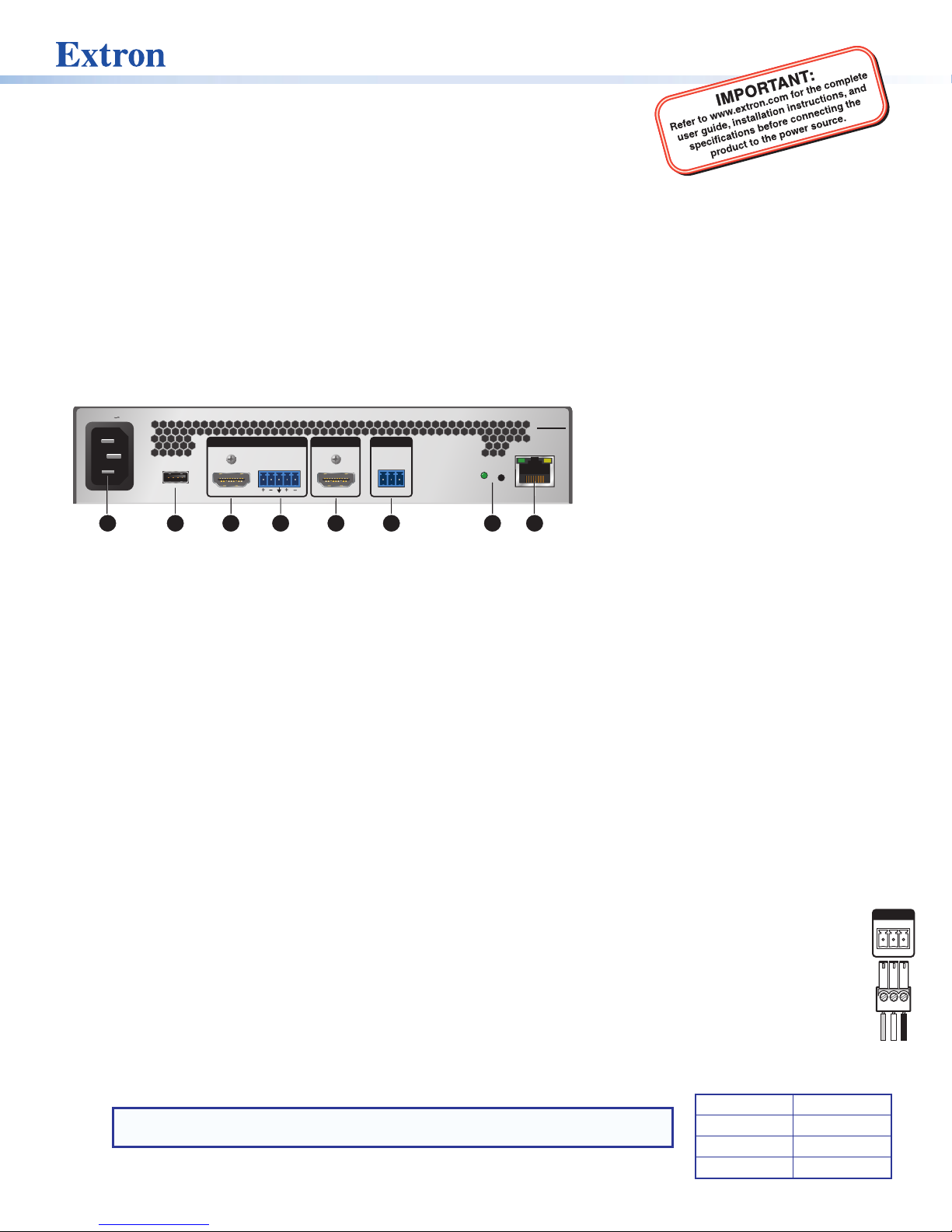
Figure 1. SME211 Rear Panel
100-240 VAC IEC connector for power input
A
USB type A receptacle for external storage device or
B
B
AUDIO
L
LINE R
HDMI HDMI
C D
E F
RS-232
RxTx G
mouse and keyboard for network setup
HDMI input
C
3.5 mm, 5-pole captive screw connector for analog
D
stereo audio input
Power Connection
100-240 VAC power input – Connect the provided IEC cord. Verify the front panel buttons and LCD illuminate (see Front
A
Panel Features on page2).
Control System and External Device Connections
The SME211 can be congured and controlled from the front panel USB Mini-B Cong port (see figure 4, D on page 2) using
SIS commands and DataViewer via telnet port 23, or from the LAN port using a standard web browser. Because the LAN port
must be connected for streaming output, Extron recommends using it for conguration, remote control, and rmware upgrades.
USB receptacle – Attach an external USB storage device to load mask images or other les to the user le system.
B
A mouse and keyboard can also be attached to this receptacle for network setup.
Remote — To control the SME211 using SIS commands over RS-232, connect the host RS-232 cable to the rear panel
F
(see the illustration at right) with a 3-pole captive screw connector for bidirectional (±5V) serial host control. The default
protocol for this port is 9600 baud, no parity, 8 data bits, 1 stop bit, and no flow control (handshaking).
Reset button and LED — The SME211 has several reset modes to return user-dened conguration settings or all
G
settings back to factory defaults. The LED blinks to indicate the desired reset mode, and provides the reset status during
the reset operation. For information on selecting the reset mode, see the SME211 User Guide.
RJ-45 Ethernet connector (LAN) — Use a standard Ethernet cable to connect to a network. The table at right has the
H
default network settings.
NOTE: To connect the SME211 directly to a computer Ethernet port, use a
crossover Ethernet cable.
SME 211
RESET
LAN
H
G
HDMI preview output
E
3.5 mm, 3-pole captive screw connector for Simple
F
Instruction Set (SIS™) control over RS-232
Reset button and LED
G
RJ-45 Ethernet connector for LAN connection
H
IP Address: 192.168.254.254
Subnet Mask: 255.255.0.0
Default Gateway: 0.0.0.0
DHCP: OFF
1
Page 2
SME211 • Setup Guide (Continued)
Slee
Input Connections
HDMI input – Connect an HDMI (or DVI with a suitable adapter) source device to input.
C
Analog audio input – Connect a balanced or unbalanced stereo line level audio device to this 5-pole 3.5 mm captive screw
D
connector. Wire the connector as shown in gure 2.
Tip
Ring
ves
Tip
Ring
LR
Tip
Sleeve
Tip
Sleeve
Unbalanced Stereo InputBalanced Stereo Input
Figure 2. Audio Input Captive Screw Connector Wiring
ATTENTION:
• The length of the exposed wires in the stripping process is critical. The ideal length is 3/16 inch (5 mm). If longer,
the exposed wires may touch, causing a short circuit between them. If shorter, the wires can be easily pulled out
even if tightly fastened by the captive screws.
• La longueur des câbles exposés est primordiale lorsque l’on entreprend de les dénuder. La longueur idéale est de
5mm (3/16inches). S’ils sont un peu plus longs, les câbles exposés pourraient se toucher et provoquer un court
circuit. S’ils sont un peu plus courts, ils pourraient sortir, même s’ils sont attachés par les vis captives.
• Do not tin the wire leads before installing into the connector. Tinned wires are not as secure in the connector and
could be pulled out.
• Ne pas étamer les conducteurs avant de les insérer dans le connecteur. Les câbles étamés ne sont pas aussi bien
xés dans le connecteur et pourraient être tirés.
LR
Do not tin
the wires!
Output Connections
HDMI preview output – Connect an HDMI (or DVI with a suitable adapter) display device to this HDMI output connector for
E
easy size and position setup and to access the internal web browser.
Front Panel Features
ALARM
CONFIG
A
CB D
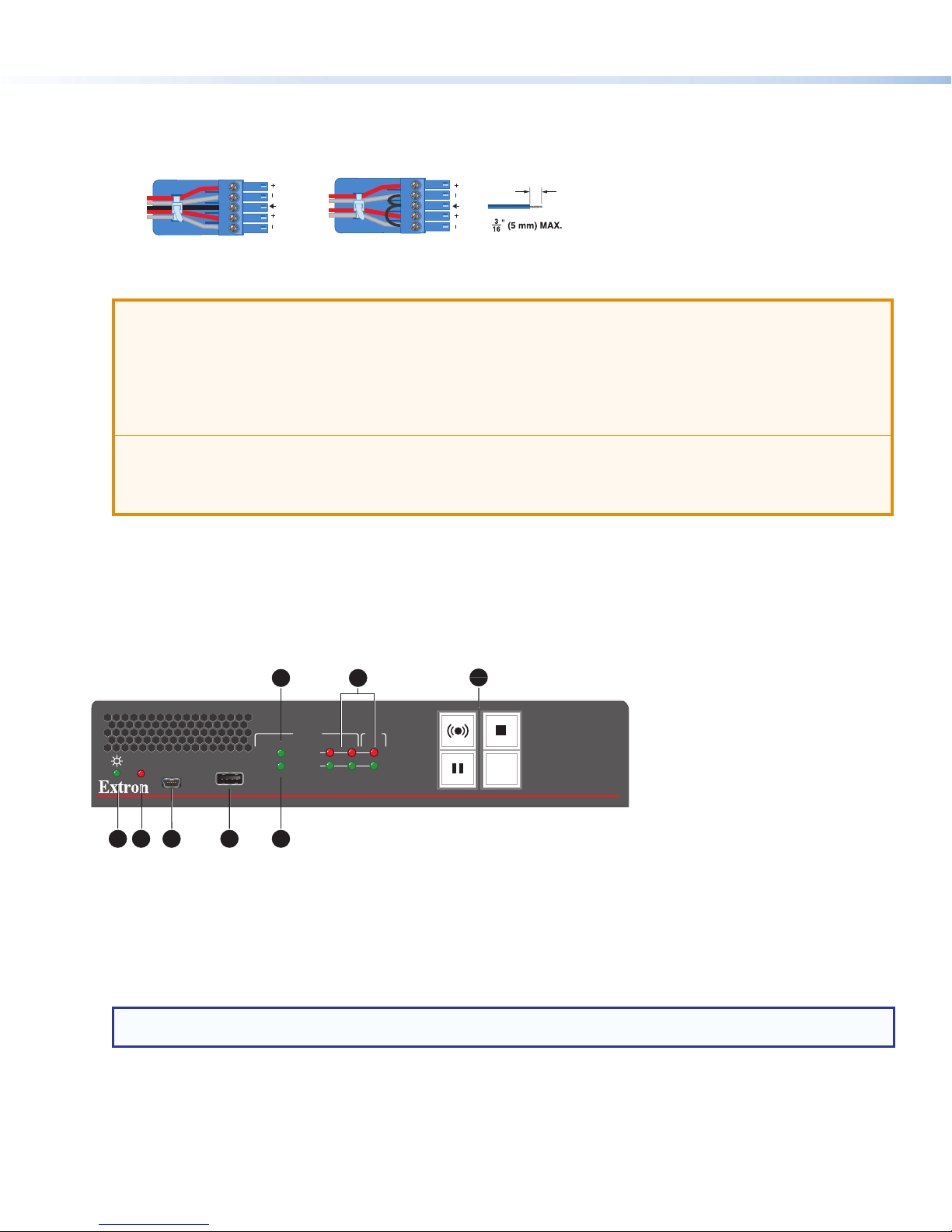
Figure 3. SME211 Front Panel
Power LED —
A
• Green — The power is on and the unit is operational.
• Blinking Green — The power is on but the unit is still booting (not operational).
Alarm LED — Lights red steadily when one or more alarms are triggered.
B
Config port — Connect a control device to this port with a USB Mini-B cable (not supplied). Use this port to send SIS
C
commands to the SME211 for device conguration and control.
NOTE: For information on using this port for device configuration and control and for a list of available SIS commands,
see the SME211 User Guide.
USB
HDCP
HDMI
E
F
INPUT
CLIP
AUDIO
HDMI LINE HDMI
G
OUT
H
MASK
STREAMING MEDIA PROCESSOR
SME 211
2
Page 3

USB storage port – Connect a USB compatible media device to this port. The device can be any standard external hard
D
drive or USB ash drive formatted with a compatible le system, or a mouse or keyboard for network setup. Compatible
formats include FAT32, VFAT, and NTFS.
HDCP LED – LED Lights red steadily if If HDCP content is detected.
E
NOTE: Streaming of HDCP content is not currently supported. When HDCP content is detected, a green screen is
displayed on the video output.
HDMI LED – LED lights green steadily when HDMI video input sync is detected.
F
Audio Signal and Clip LEDs
G
• Audio Output Indicators – Stacked red (signal clipping) and green (signal present) LEDs for HDMI and line input
channels.
• Audio Output Indicators – Stacked red (signal clipping) and green (signal present) LEDs for the output channel.
For both the Audio Input and Audio Output indicators, the green signal LED varies in brightness corresponding to the input
signal level. It begins to light at -60 dBFS, increasing to full intensity corresponding to signal level increases. When the
signal level reaches -3 dBFS or above, the red clipping LED lights and remains lit as long as the signal remains about -3
dBFS. When it falls below that level, the red LED remains lit for 200 milliseconds, after which the display resumes real-time
monitoring of the signal level.
Streaming controls with LED indicators – The front panel buttons control all enabled streams concurrently:
H
• Stream – Press to start live streaming or resume live streaming after pausing. When the unit is streaming, the LED
lights red steadily. When the unit is not streaming, the LED lights amber steadily. If the unit is unable to stream (for
example all individual streams are disabled) the stream LED ashed RED rapidly.
• Stop – Press to stop the active streaming. When the unit is not streaming, the LED lights green steadily. When
streaming is paused, the LED lights amber steadily.
• Pause – Press to pause streaming. When pressed, the green Pause button blinks amber to indicate streaming is
paused. When streaming is paused, the LED lights amber steadily. Press Stream or press Pause to resume streaming
or Stop to halt the streaming.
NOTE: When paused, the last full frame of active video is held as a still image.
• Mask – Press
mask. Press the button again to transition cleanly back to streaming video from the HDMI input.
Powering Up
When applying power, the unit undergoes a self-testing sequence. The power led starts blinking green when the power is
connected but the unit is still booting. The line of green LEDs in the input and output section of the front panel will light and the
streaming controls will light amber.
MASK
to transition cleanly from streaming live video from the HDMI input to streaming a selected still image
Streaming
The SME 211 supports unicast and multicast streaming protocols, including RTMP.
NOTE: The confidence stream on the web-based UI supports both audio and video.
To decode the streams:
To view the preview stream, go to the embedded web page AV Controls Panel. SME 211 streams can also be decoded using
an Extron SMD202 decoder or compatible third party players such as VLC and QuickTime.
Presets
Three types of presets are supported:
Encoder Presets – These presets allow quick switching between various encoder proles based on resolution and bit rates.
There are 64 encoder presets available.
Streaming Presets – These presets allow quick switching between various streaming proles. There are 16 presets for each
stream method that can be saved or recalled from the internal web pages.
Combined Encoding and Streaming Presets – These presets combine the features of both Encoding and Streaming Presets.
3
Page 4

Accessing Internal Content
?
The SME211 has internal memory reserved for local content. Internal content is viewed from the web-based user interface Files
Management tab. See the SME211 User Guide or the SME211 Help File for complete instructions.
For example, Mask images can be uploaded to the SME 211 using the File Upload Utility or a SFTP client such as Filezilla, a free
FTP program. Connect to the SME211 at sftp://<SME 211 IP>:22022. Log in using “admin” or “user” credentials. See the
SME 211 User Guide for more information.
About the Web-based User Interface
The web-based user interface can view, congure, and control the SME211 with a PC from the LAN port using a standard web
browser. This section details how to access the web-based user interface. For more information on using the web-based user
interface, see the SME211 User Guide available on the Extron website or click the Help button to open the SME211 Help File.
Accessing the Web-based User Interface
NOTE: The SME 211 can be accessed in Windows using Google
®
Chrome™ version 48 or higher (recommended), Microsoft®
Internet Explorer® version 10 or higher, or Explorer Mozilla® Firefox® (version 35 or higher), and on a Mac® OS® platform
(Mac OS X or higher) using Safari® (version 8 or higher) (see the SME 211 User Guide for current compatibility).
Open a web browser on the control computer and enter the IP address of the SME211 into the address bar (for example,
192.168.254.254). Press <Enter>. The default user interface page opens.
The AV Controls panel on the left remains open unless closed by the user. It provides streaming controls, input mute settings,
and displays an audio output level meter. The Device Status tab displays input, output, and encoder information, along with
encode and stream presets. Click the help le button (
and tabs within the web-based user interface to open the SME211 Help File for more information.
© 2018 Extron Electronics — All rights reserved. www.extron.com
All trademarks mentioned are the property of their respective owners.
4
) in the top right corner of the default page and on the various pages
68-3158-50 Rev. A
05 18
 Loading...