

Page 1
S-video (YC) Component Video (Y, R-Y, B-Y)Composite Video
3
SME 100 • Setup Guide
The Extron SME 100 is a live streaming media encoder that interfaces with DVI, RGB, HDTV,
and standard denition signals for delivering media over IP networks. It features a three input video and audio switcher, plus
buffered loop-throughs for simplied integration into AV systems. The SME 100 uses H.264 / MPEG-4 AVC encoding to output an
IP stream over the Internet (or over an intranet) that can easily be decoded and viewed on PCs or H.264 compatible devices.
The SME100HD (part number 60-1061-01) supports both high denition and standard denition output rates. The SME100SD
(part number 60-1061-02) supports standard denition output rates only.
This guide provides basic instructions for an experienced installer to set up and operate the SME 100. Installation and service
must be performed by authorized personnel only.
NOTE: See the SME 100 User Guide for complete installation, configuration, operation, and mounting
information. The user guide is available at www.extron.com.
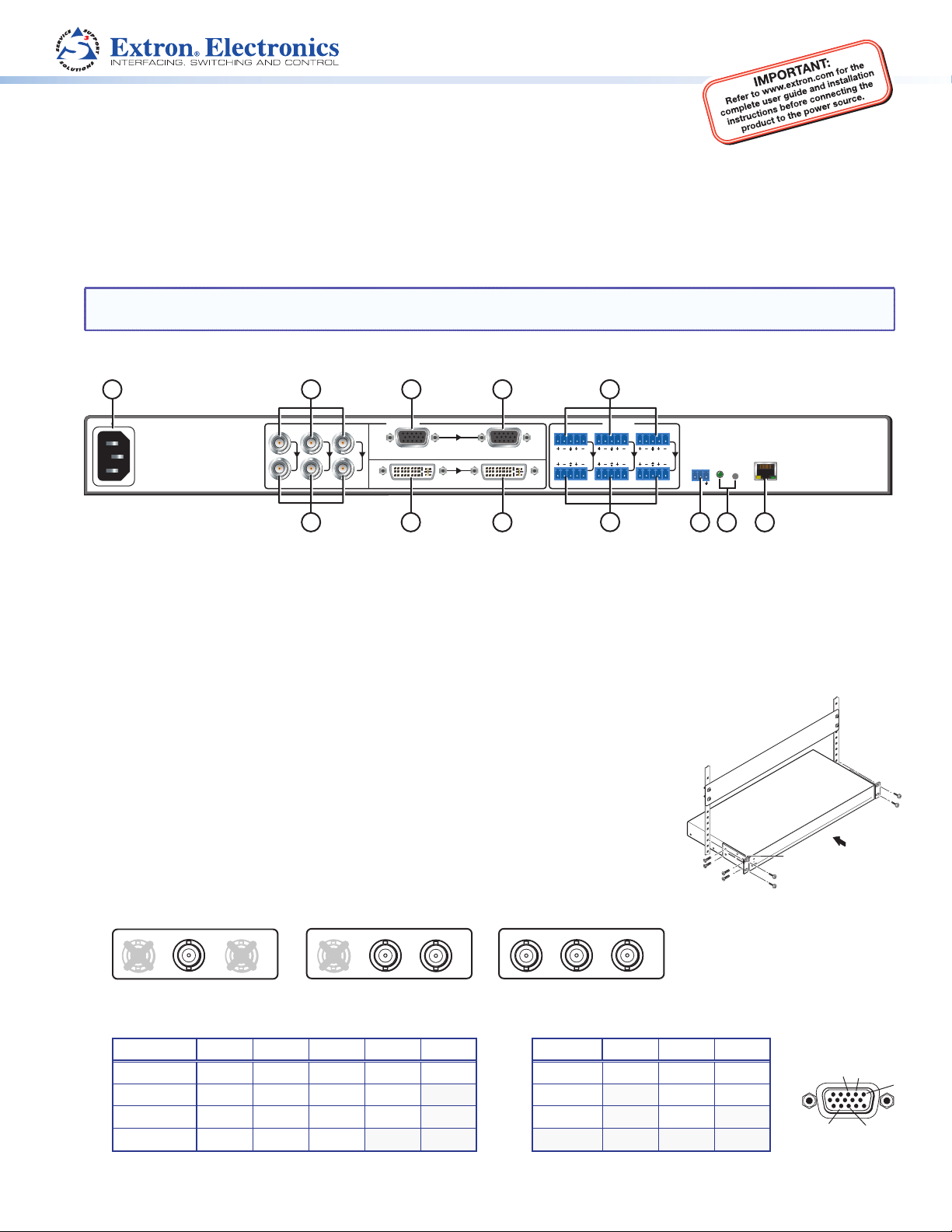
Rear Panel Overview
1
2
4 5
8
100-240VAC
50/60 Hz
0.5A MAX
1
Y/
R-Y
VID
3
AC power connector
a
Component, S-video, composite BNC connectors (input 1)
b
Component, S-video, composite BNC buffered loop connectors
c
15-pin HD connector (input 2) with EDID emulation
d
15-pin HD buffered loop connector
e
DVI connector (input 3) with EDID emulation
f
B-Y/
C
INPUTS
2
RGB/R-Y,Y,B-Y/YC/VID
3
DVI-D
6 7 10
BUFFERED LOOP
BUFFERED LOOP
LR2LR3LR
g
h
i
j
k
l
AUDIO
1
9
DVI buffered loop connector
Audio captive screw connectors (inputs 1 – 3)
Buffered loop audio captive screw connectors
RS-232 connector
Reset button and LED
RJ-45 Ethernet connector
Installation
Step 1 — Mount the SME 100
Turn all devices off and unplug their power cords. Verify that the SME 100 is disconnected from
the power source. Mount the SME 100 to a rack using the mounting brackets included with the
unit (see image at right).
Step 2 — Connect Input Devices
Connect input devices to at least one of the following connectors.
z Connect a video input device to the component, S-video, or composite BNC connectors
(input 1; b). See the examples below to connect the necessary signal format.
1
R-Y
Y/
VID
B-Y/
C
1
R-Y
Y/
VID
B-Y/
C
1
R-Y
Y/
VID
B-Y/
C
RESET
LAN
ACT LINK
RS-232
Tx Rx
1211
Rack Mount
Bracket
z Connect a video input device to the 15-pin HD connector (input 2;
Signal Pin 1 Pin 2 Pin 3 Pin 13 Pin 14 Signal Pin 1 Pin 2 Pin 3
RGBHV R G B H V YUV R-Y Y B-Y
RGBS R G B S S-video Y C
RGBcvS R G B S Video Vid
RGsB R Gs B
z Connect a high resolution digital input device to the DVI connector (input 3;
). See pin congurations below.
d
).
f
2
1
14
13
1
Page 2
SME 100 • Setup Guide (Continued)
Slee
LR
Balanced Audio Output
Slee
Unbalanced Audio Output
RS-232 Connected Device
SME100 (
)
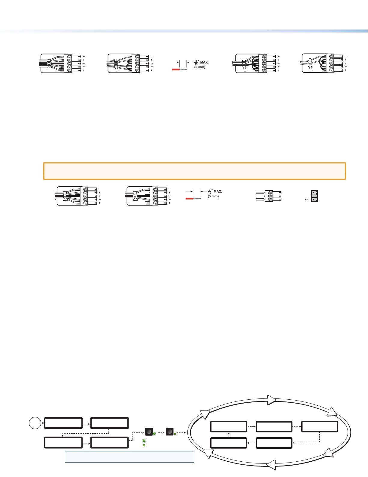
z Connect audio input devices to the audio captive screw connectors (inputs 1 through 3;
) using cables with balanced or
h
unbalanced 3.5 mm, 5-pole captive screw connectors. See the image below to wire the connectors.
Tip
Ring
ves
Tip
Ring
Balanced Stereo Input
LR
Tip
Sleeve
Tip
Sleeve
Unbalanced Stereo Input
LR
Do not tin the wires!
Tip
Ring
Sleeve
Balanced Mono Input
(high impedance)
LR
Tip
Sleeve
Unbalanced Mono Input
Step 3 — Connect Buffered Loop Output Devices (Optional)
If necessary, connect output devices to the following buffered loop connectors. Buffered loop connectors output the input video
that is connected to a similar input connector (for example, BNC buffered loop connectors output BNC video).
z Connect a video output device to the component, S-video, composite BNC buffered loop connectors (
z Connect a video output device to the 15-pin HD buffered loop connector (
z Connect a high resolution digital output device to the DVI buffered loop connector (
z Connect audio output devices to the buffered loop audio captive screw connectors (
e
).
).
g
) using cables with balanced or
i
unbalanced 3.5 mm, 5-pole captive screw connectors. See the image below to wire the connectors.
ATTENTION: For unbalanced audio, connect the sleeves to the ground contact. DO NOT connect the
sleeves to the negative (–) contacts.
Tip
Ring
ves
Tip
Ring
LR
Tip
Sleeves
Tip
LR
Do not tin the wires!
Receive
Transmit
Ground
c
).
Tx
Rx
Step 4 — Connect RS-232 Control Device (Optional)
If necessary, connect a host computer or control system to the RS-232 connector (j). Use this port to send Simple Instruction
Set (SIS™) commands to the SME 100 for device conguration and control. The default protocol for this port is:
9600 baud rate, no parity bit, 8 data bits, 1 stop bit, and no flow control (handshaking).
Step 5 — Connect the SME 100 to the Network
Connect one end of an RJ-45 cable to the Ethernet connector (l) on the SME 100. Connect the other end of the RJ-45 cable to
a router or switch to connect the SME 100 to a network.
The LEDs on the Ethernet connector indicate the status of the network connection. The green LED lights when connected to a
network. The amber LED ickers as the SME 100 actively communicates with a network.
Step 6 — Connect Control PC and Viewing Devices to the SME 100 Network
Connect one end of an RJ-45 cable to a control PC or viewing device. Connect the other end of the RJ-45 cable to a router or
switch to connect the control PC or viewing device to the network.
Step 7 — Power On the SME 100 and All Devices
Connect a standard IEC power cord into the AC power connector (a) of the SME 100 and plug it to a 100 to 240 VAC,
50 Hz or 60 Hz power source. Connect the power cords of the input and output devices and turn them on.
Powering Up
When applying power to the SME 100, the unit undergoes a self-testing sequence (see the image below). After the testing
sequence is complete (and when the device is not being congured), the default display cycle is shown on the LCD display.
The default display cycle shows the model name/rmware version, active input/output signal format, active input/horizontal and
vertical scan rate, stream mode/output resolution,
and stream method/AV bit rate in kilobits per second (Kbps).
Power
On
2
EXTRON
ELECTRONICS
LOADING
FIRMWARE
NOTE:
2
SME 100 HD/SD
sec.
30
sec.
FW V2.00
SME 100 HD/SD
INITIALIZING
~4
sec.
The information shown in the default display cycle
45
sec.
Key
All input LEDs flash
once in sequence.
1
= flashing
= lit
may differ depending on the active input and type of video signal.
3
1
sec.
Last active input
LED remains lit
(here input 3).
1
sec.
Default Display Cycle
2
SME 100 HD/SD
FW V2.00
2 sec.
UNICAST RTP
BR 521 Kbps
sec.
2
sec.
In#1 YUVp/HD
480p
OUTPUT A/V
640 x 480
2
sec.
In#1 YUVp/HD
31kHz 60Hz
2 sec.
Page 3

Front Panel Overview
ab cd ef
V
S
GS
1
CONFIG
Config port — Connect a control PC to this port using a Mini-B USB cable (not supplied). Use this port to send
a
3
2
MENU NEXT
ADJUST
STREAMING MEDIA ENCODER
SIS commands to the SME 100 for device conguration and control.
NOTE: For information on using this port for device configuration and control and for a list of available
SIS commands, see the SME 100 User Guide.
Input selection buttons — These buttons select and switch inputs. A green LED lights to indicate the selected input. A
b
blinking LED indicates an audio breakaway input. An input that does not contain an input source can still be selected, but the
LCD display will show No Signal.
z Button 1 selects input 1 (component video, S-video, or composite video).
z Button 2 selects input 2 (component video, S-video, composite video, and RGB video [RGBHV, RGBS, RGsB, RGBcvS]).
z Button 3 selects input 3 (DVI-D video).
Menu button — This button navigates through the primary conguration menus of the SME 100.
c
Next button — This button navigates through the conguration submenus of each primary menu.
d
LCD display — This display shows the device settings and menu conguration information.
e
Adjust knobs — These are used with the Menu and Next buttons to adjust the settings of the conguration menus.
f
NOTE: The front panel buttons on the SME 100 can be locked so that configuration using the front panel is not
possible. Refer to the SME100 User Guide for more information.
SME 100
Conguring the Network Settings of the SME 100 Using the Front Panel
The SME 100 contains several primary conguration menus and one hidden menu that are available on the front panel
LCD display. In order to access the web-based user interface of the SME 100, the network settings may need to be congured.
The SME 100 is pre-congured with the following network settings:
IP address: 192.168.254.254
Subnet mask: 255.255.0.0
Gateway address: 0.0.0.0
NOTE: With these settings, the control PC and viewing devices must use IP addresses within the range of 192.168.0.1
through 192.168.254.253 and use the same subnet mask.
Use the following procedure to congure the network settings of the SME 100, if necessary.
1. Press the Menu button repeatedly until the View Comm Settings menu is shown on the LCD display.
2. Press and hold the Next and Input 3 button simultaneously
for approximately three seconds. This changes the View
Comm Settings menu to the Edit Comm Settings menu.
3. Press the Next button repeatedly to cycle to the IP address
(IP), subnet mask (SM), and default gateway (GM) submenus.
4. Change the IP address, subnet mask, and default gateway as
necessary (default values shown).
To congure the addresses:
z Cycle to the desired octet by rotating the left Adjust
knob ([).
z Adjust the value of the octet by rotating the right Adjust
knob ({).
5. Save the network settings by pressing the Menu button. The
network settings of the SME 100 are now congured.
IEW COMM
ETTIN
Next
+
Input 3
EDIT COMM
SETTINGS
Next
G 000.000.
M 000.000
Change Value
Select
Valid addresses
Octet
are 0 – 254.
Next Next
SERIAL PORT
9600 RS232
Baud Rates
300 600 1200 1800,
2400 4800 9600 (default),
19200 38400 57600 115200
Next
S
M
Select
Octet
255.255.
000.000
Change Value
Valid addresses
are 0 – 255.
Next
DHCP MODE
<OFF> ON
DHCP Mode
Turn DHCP
on or off.
I
192.168.
P
254.254
Change Value
Select
Valid addresses
Octet
are 0 – 254.
Next
3
Page 4

SME 100 • Setup Guide (Continued)
About the Web-based User Interface
The web-based user interface is used to view, congure, and control the SME 100. This section details how to access the
web-based user interface and install media player software. For more information on using the web-based user interface, see the
SME 100 User Guide.
NOTE: SME 100 firmware versions 2.0 and higher use the Extron streaming media player (SMP) available for download from
the SME100 file management page or from the SME100 download page at www.extron.com.
Accessing the Web-based User Interface
Open a web browser (Microsoft® Internet Explorer® version 7 or higher is recommended) on the control PC or viewing device and
type the IP address of the SME100 into the address bar (for example, http://192.168.254.254). The Live View page appears in the
browser (see gure 1).
NOTE: The SME100 can also be accessed in Windows using Firefox® (version 15 or higher), or Chrome™ (version 21 or
higher) and on a Mac® OS® platform (version 10.6 or higher) using Safari® (version 5.1 or higher). See the SME100 User
Guide at www.extron.com for current compatibility.
Installing Media Player Software
The SME 100 requires a media player plugin to view live streams.
Extron recommends using the Extron SMP plugin for streaming.
Use the following procedure to install the SMP plugin.
NOTE: VLC media player® and QuickTime® media player are
compatible with the SME100. For information on installing
either player, see the SME 100 User Guide.
1. Access the web-based user interface of the SME 100
(see "Accessing the Web-based User Interface" above).
2. From the Live View tab (
may appear. If a blue player window is displayed (see gure 1),
it means a version of SMP media player is already installed and
nothing more needs to be done.
If the screen shown in the Live View tab in gure 2 appears,
click the rst here link(b).
3. A File Download window appears. Click the SMP-1.0.0.2-win32.exe le to
download and start the SMP media player installation.
Follow the directions on the remaining prompts to install the player.
4. After the media player installation has nished, close and restart the browser.
Optionally, you can reboot the control PC or viewing device.
5. Access the web-based user interface (see
"Accessing the Web-based User Interface" above). The
Live View page should now contain a blue player window (see
gure1). Click the Play icon to view a live stream.
in gure 1 and gure 2), two screens
a
1
Figure 1. Live View - SMP Player Installed
EXE
SMP-1.0.0.2-win32.exe
1
2
NOTES:
• When a live stream is played, by default it uses the
unicast RTP transport protocol. To change the
transport protocol and other various settings on the
SME100, click on the Conguration tab, then click
on the Encoder Settings link on the left sidebar.
• Clicking on the © icon located in the upper right hand
corner of the web page lists the licensed third-party
software that is used by the SME100.
Extron Headquarters
+1.800.633.9876 (Inside USA/Canada Only)
Extron Europe
+31.33.453.4040
4
© 2013 Extron Electronics — All rights reserved. All trademarks mentioned are the property of their respective owners. www.extron.com
Extron Asia
+65.6383.4400
Extron Japan
+81.3.3511.7655
Figure 2. Live View - SMP Player Installation Link
Extron China
+86.21.3760.1568)
Extron Middle East
+971.4.2991800
Extron Korea
+82.2.3444.1571
Extron India
+91.80.3055.3777
68-2167-50
Rev. B 01 13
 Loading...