

Page 1
SI 3CT LP
User’s Guide
Frame Construction Ceiling Installation
1
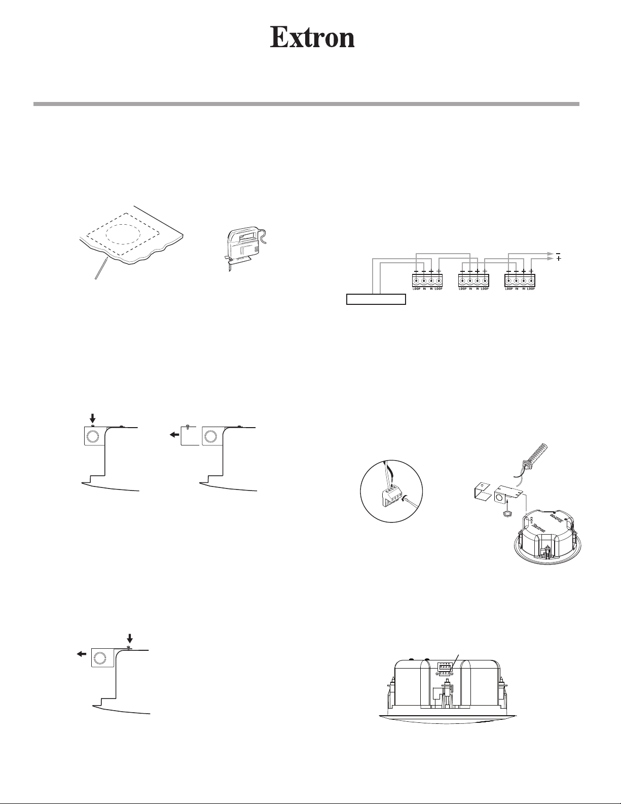
Take the cutout template from the packaging box and
punch out along the larger perforated circle. Place the
cutout template against the ceiling and trace along the inside
circle. Carefully cut out the ceiling material along the circle.
Ceiling Speaker
Cut material.
c. Insert the conduit(s) into the knockout opening(s) and
secure the conduit to the cover with the locking nut.
d. Pull the speaker wires from the conduit, strip 0.2” (5 mm)
from the wire ends (do not tin the wires), and secure the
wires into the 4-pole captive screw connector. To connect
speakers in parallel, see the wiring diagram below.
Trace template.
2
The side terminal cover, as illustrated in step 3f, must first
be removed before wiring the speaker.
Loosen the single top screw of the side terminal cover and
pull the side terminal cover straight out. See the illustration
below.
Loosen
screw.
Side View of Input Terminal
Side Terminal
Cover
3
a. Remove the top terminal cover (see the illlustration in
step 3f) by loosening (do not remove) both top screws,
sliding the top terminal cover away from the screws, and
removing the cover, as shown here.
70 V To Speakers
Power Amplifier
Speaker 1 Speaker 2 Speaker 3
e. Bring the speaker up to the bottom of the hole in the
ceiling.
f. Plug the wired connector from step 3d into the speaker’s
audio input connector. Secure the top terminal cover
with the two top screws that were loosened in step 3a;
hook the side terminal cover to the top terminal cover; and
secure the side terminal cover in place with the screw that
was loosened in step 2.
See NOTE below.
Top Terminal
Side Terminal
Cover
4-pole Captive
Screw Connector
Cover
N Installation in a plenum-rated environment
requires a wire gauge of 14 AWG to 18 AWG.
Loosen
two screws.
Top Terminal
Cover
b. Remove the knockout(s) from the top terminal cover
depending on the direction from which the conduit(s) will
be entering the cover.
4-pole Captive
Screw Connector
33-1351-01
Rev. B
IN
LOOP IN LOOP
Front View of Input Terminal
68-1263-01 Rev. B
09 07
1
Page 2
SI 3CT LP
User’s Guide
cont’d
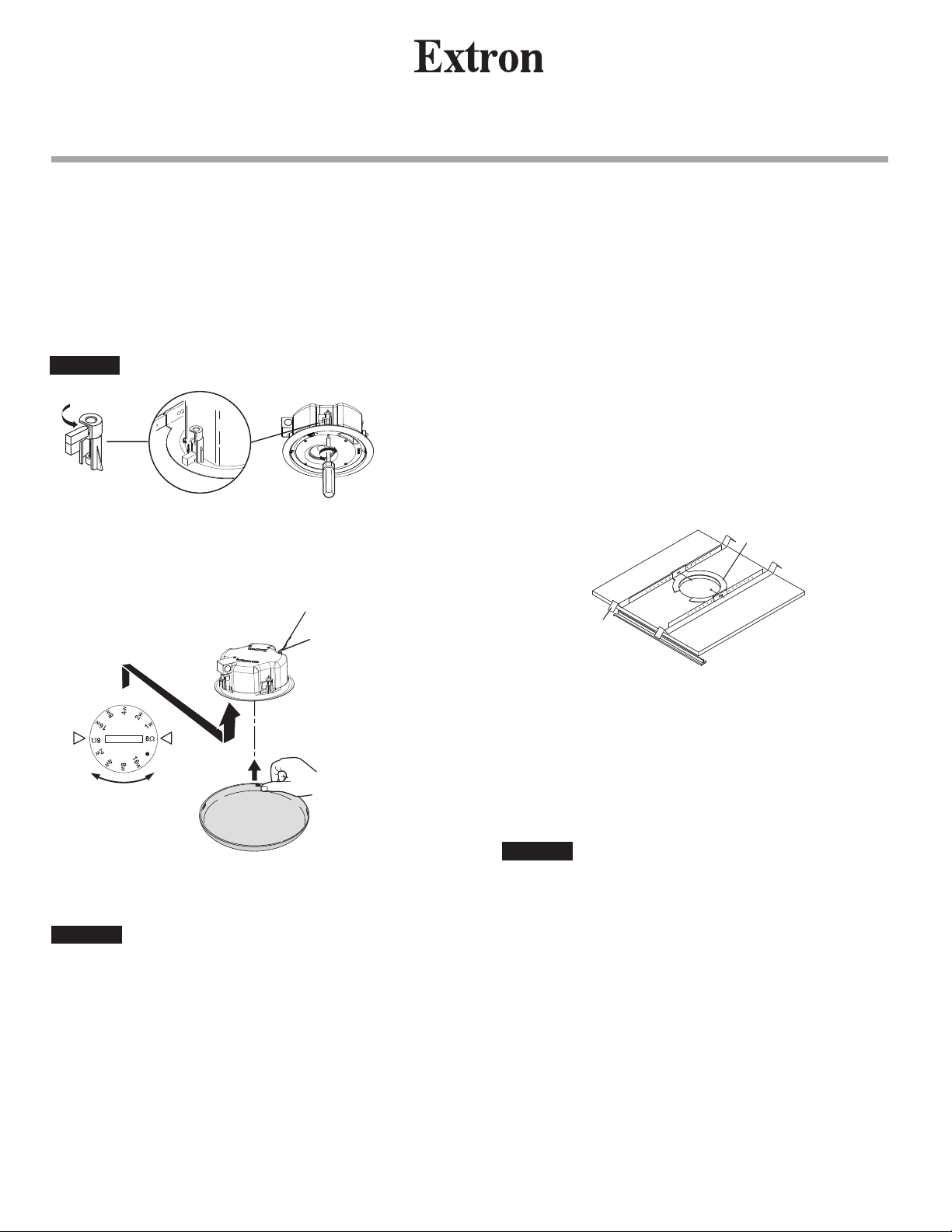
4
Loosen the four screws on the front baffle (counter
clockwise) 1/2 turn. Insert the speaker in the ceiling hole,
then tighten the screws (clockwise) until the dog legs clamp
the speaker to the ceiling. See the following illustration.
CAUTION
Do not overtighten screws.
5
Connect a secondary support line from the seismic tab to a
secure support point, as shown below.
Ceiling Speaker
Suspended Ceiling InstallationFrame Construction Ceiling Installation,
1
Remove the ceiling tile where the speaker is to be installed.
2
Cut the hole in the tile (see step 1 on page 1).
3
Bring the speaker cable through the hole of the cut tile,
then reinstall the tile.
4
Remove the adjacent tile. Place 2 V-rails and 1 C-ring
across the tile where speaker is to be installed. Bring the
speaker up to the bottom of the hole in the ceiling tile.
C-ring
Seismic Tab &
Support Line
70 Volt
100 Volt
Apply 4 pieces of
black putty (supplied),
Adjusting the Tap Selector.
Set the rotary tap selector (shown above) to the proper
position.
CAUTION
Install the speaker grille.
Do not turn the tap selector to the 8 Ω position
when using 70 V / 100 V lines.
equally spaced 90° apart,
to the upper inside edge
of the grille.
V-rail
5
Connect the wires to the speaker terminal connector (see
step 3 on page 1).
6
Loosen the four screws on the front baffle (counter
clockwise) 1/2 turn. Then tighten the screws (clockwise)
until the dog legs clamp the speaker to the ceiling.
CAUTION
Do not overtighten screws.
7
Connect a secondary support line from the seismic tab to
a secure support point (see step 5 of Frame Construction
Ceiling Installation on this page).
8
Set the rotary tap selector and install the grille (see step 5 of
Frame Construction Ceiling Installation on this page).
2
Page 3
User’s Guide
SI 3CT LP
Ceiling Speaker
Painting the Speaker Baffle
Tear along the smaller perforated line of the cutout
template marked as a paint shield. Push it into the front
baffle of the speaker. Paint the front. Remove the paint
shield after the paint has dried.
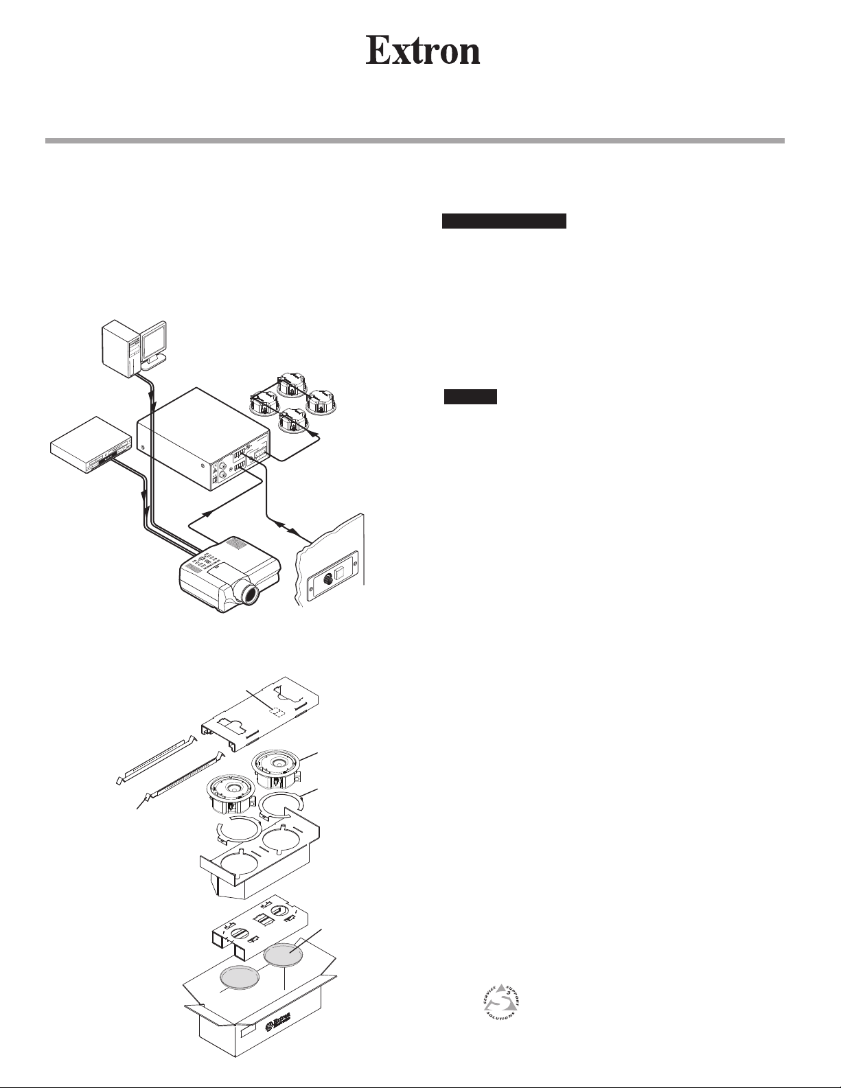
Application diagram
Extron
SI 3CT LP
PC
VGA w/
Audio Cable
DVD/VCR Combo
Composite
Audio RCA
Variable
REMOTE
10V
INPUTS
VOL/MUTE
(MONO)
L
POWER
R
12V
3A MAX
Projector
MPA 181T
LISTED
1T23
I.T.E.
US
COM 70V
OUTPUTS
C
70V
R
4/8 Ohms
(MONO)
L
Low Profile Ceiling
Speakers
Extron
MPA 181T
Mini Power Amplifier
MUTE
VCM 100
VOLUME
Extron
VCM 100 AAP
Volume/Mute Controller
Specifications
Acoustic & Electrical
Speaker type................................. Low profile ceiling speaker with metal back can
Frequency response..................... 75 Hz to 18 kHz, -10 dB, half space
Power capacity.............................. 16 W continuous pink noise
32 W continuous program
Nominal sensitivity........................ 83 dB, 1 W, 1 m, 16 W tap, half space
Nominal coverage angle............... 170° conical coverage
Nominal impedance ..................... 8 ohms
Rotary switch taps........................ 70V: 16 W, 8 W, 4 W, 2 W, 1 W
100V: 16 W, 8 W, 4 W, 2 W
Driver............................................ 3” (76 mm) full range paper cone with moisture
resistant coating
Input/output connector.................. (1) 5 mm captive screw connector, 4-pole for input
and loop-through
General
Package ....................................... 2 speakers (1 pair)
Temperature/humidity.................... Storage: -40 to +158 °F (-40 to +70 °C) /
10% to 90%, noncondensing
Operating: +32 to +122 °F (0 to +50 °C) /
10% to 90%, noncondensing
Mounting....................................... Ceiling mountable with included hardware: V-rails for
2’ x 4’ (600 mm x 1200 mm) ceiling tiles, and C-rings
Enclosure type.............................. Formed steel back can; high impact, fire-resistant
(UL94V-0), polystyrene plastic baffle/rim
Enclosure outer dimensions.......... 4.0” H x 9.9” diameter (102 mm x 251 mm diameter)
Cutout dimensions........................ 8.82” diameter (224 mm diameter)
Product weight.............................. 6 lbs (2.72 kg) each speaker
Shipping weight............................. 22 lbs (9.98 kg) per pair w/ mounting kit package
Listings ......................................... UL 2043, UL1480
Compliances ................................ CE, NFPA90, NFPA70A
Warranty ....................................... 5 years parts and labor
NOTE: All nominal levels are at ±10%.
NOTE: Specifications are subject to change without notice.
Packaging
V-rails (4)
Mounting Screws
& Putty
Speakers
C-rings
Speaker Grilles
www.extron.com
Extron Electronics, USA
1230 South Lewis Street
Anaheim, CA 92805
800.633.9876 714.491.1500
FAX 714.491.1517
Extron Electronics, Asia
135 Joo Seng Rd. #04-01
PM Industrial Bldg., Singapore 368363
+800.7339.8766 +65.6383.4400
FAX +65.6383.4664
Extron Electronics, Europe
Beeldschermweg 6C
3821 AH Amersfoort, The Netherlands
+800.3987.6673 +31.33.453.4040
FAX +31.33.453.4050
Extron Electronics, Japan
Kyodo Building, 16 Ichibancho
Chiyoda-ku, Tokyo 102-0082
Japan
+81.3.3511.7655 FAX +81.3.3511.7656
3
 Loading...