

Page 1
User’s Manual
RAC 104
Remote Volume and Tone Controller
68-782-01 Rev. C
12 08
Page 2
Precautions
Safety Instructions • English
This symbol is intended to alert the user of important
operating and maintenance (servicing) instructions
in the literature provided with the equipment.
This symbol is intended to alert the user of the
presence of uninsulated dangerous voltage within
the product's enclosure that may present a risk of
electric shock.
Caution
Read Instructions • Read and understand all safety and operating
instructions before using the equipment.
Retain Instructions • The safety instructions should be kept for future
reference.
Follow Warnings • Follow all warnings and instructions marked on the
equipment or in the user information.
Avoid Attachments • Do not use tools or attachments that are not
recommended by the equipment manufacturer because they may be
hazardous.
Consignes de Sécurité • Français
Ce symbole sert à avertir l’utilisateur que la
documentation fournie avec le matériel contient des
instructions importantes concernant l’exploitation
et la maintenance (réparation).
Ce symbole sert à avertir l’utilisateur de la présence
dans le boîtier de l’appareil de tensions dangereuses
non isolées posant des risques d’électrocution.
Attention
Lire les instructions• Prendre connaissance de toutes les consignes de
sécurité et d’exploitation avant d’utiliser le matériel.
Conserver les instructions• Ranger les consignes de sécurité afin de
pouvoir les consulter à l’avenir.
Respecter les avertissements • Observer tous les avertissements et
consignes marqués sur le matériel ou présentés dans la documentation
utilisateur.
Eviter les pièces de fixation • Ne pas utiliser de pièces de fixation ni
d’outils non recommandés par le fabricant du matériel car cela
risquerait de poser certains dangers.
Sicherheitsanleitungen • Deutsch
Dieses Symbol soll dem Benutzer in der im
Lieferumfang enthaltenen Dokumentation
besonders wichtige Hinweise zur Bedienung und
Wartung (Instandhaltung) geben.
Dieses Symbol soll den Benutzer darauf aufmerksam
machen, daß im Inneren des Gehäuses dieses
Produktes gefährliche Spannungen, die nicht isoliert
sind und die einen elektrischen Schock verursachen
können, herrschen.
Achtung
Lesen der Anleitungen • Bevor Sie das Gerät zum ersten Mal verwenden,
sollten Sie alle Sicherheits-und Bedienungsanleitungen genau
durchlesen und verstehen.
Aufbewahren der Anleitungen • Die Hinweise zur elektrischen Sicherheit
des Produktes sollten Sie aufbewahren, damit Sie im Bedarfsfall darauf
zurückgreifen können.
Befolgen der Warnhinweise • Befolgen Sie alle Warnhinweise und
Anleitungen auf dem Gerät oder in der Benutzerdokumentation.
Keine Zusatzgeräte • Verwenden Sie keine Werkzeuge oder Zusatzgeräte,
die nicht ausdrücklich vom Hersteller empfohlen wurden, da diese eine
Gefahrenquelle darstellen können.
Instrucciones de seguridad • Español
Este símbolo se utiliza para advertir al usuario sobre
instrucciones importantes de operación y
mantenimiento (o cambio de partes) que se desean
destacar en el contenido de la documentación
suministrada con los equipos.
Este símbolo se utiliza para advertir al usuario sobre
la presencia de elementos con voltaje peligroso sin
protección aislante, que puedan encontrarse dentro
de la caja o alojamiento del producto, y que puedan
representar riesgo de electrocución.
Precaucion
Leer las instrucciones • Leer y analizar todas las instrucciones de
operación y seguridad, antes de usar el equipo.
Conservar las instrucciones • Conservar las instrucciones de seguridad
para futura consulta.
Obedecer las advertencias • Todas las advertencias e instrucciones
marcadas en el equipo o en la documentación del usuario, deben ser
obedecidas.
Evitar el uso de accesorios • No usar herramientas o accesorios que no
sean especificamente recomendados por el fabricante, ya que podrian
implicar riesgos.
Warning
Power sources • This equipment should be operated only from the power source
indicated on the product. This equipment is intended to be used with a main
power system with a grounded (neutral) conductor. The third (grounding) pin is
a safety feature, do not attempt to bypass or disable it.
Power disconnection • To remove power from the equipment safely, remove all
power cords from the rear of the equipment, or the desktop power module (if
detachable), or from the power source receptacle (wall plug).
Power cord protection • Power cords should be routed so that they are not likely to
be stepped on or pinched by items placed upon or against them.
Servicing • Refer all servicing to qualified service personnel. There are no user-
serviceable parts inside. To prevent the risk of shock, do not attempt to service
this equipment yourself because opening or removing covers may expose you to
dangerous voltage or other hazards.
Slots and openings • If the equipment has slots or holes in the enclosure, these are
provided to prevent overheating of sensitive components inside. These openings
must never be blocked by other objects.
Lithium battery • There is a danger of explosion if battery is incorrectly replaced.
Replace it only with the same or equivalent type recommended by the
manufacturer. Dispose of used batteries according to the manufacturer's
instructions.
Avertissement
Alimentations• Ne faire fonctionner ce matériel qu’avec la source d’alimentation
indiquée sur l’appareil. Ce matériel doit être utilisé avec une alimentation
principale comportant un fil de terre (neutre). Le troisième contact (de mise à la
terre) constitue un dispositif de sécurité : n’essayez pas de la contourner ni de la
désactiver.
Déconnexion de l’alimentation• Pour mettre le matériel hors tension sans danger,
déconnectez tous les cordons d’alimentation de l’arrière de l’appareil ou du
module d’alimentation de bureau (s’il est amovible) ou encore de la prise secteur.
Protection du cordon d’alimentation • Acheminer les cordons d’alimentation de
manière à ce que personne ne risque de marcher dessus et à ce qu’ils ne soient
pas écrasés ou pincés par des objets.
Réparation-maintenance • Faire exécuter toutes les interventions de réparation-
maintenance par un technicien qualifié. Aucun des éléments internes ne peut être
réparé par l’utilisateur. Afin d’éviter tout danger d’électrocution, l’utilisateur ne
doit pas essayer de procéder lui-même à ces opérations car l’ouverture ou le
retrait des couvercles risquent de l’exposer à de hautes tensions et autres dangers.
Fentes et orifices • Si le boîtier de l’appareil comporte des fentes ou des orifices,
ceux-ci servent à empêcher les composants internes sensibles de surchauffer. Ces
ouvertures ne doivent jamais être bloquées par des objets.
Lithium Batterie • Il a danger d'explosion s'll y a remplacment incorrect de la
batterie. Remplacer uniquement avec une batterie du meme type ou d'un ype
equivalent recommande par le constructeur. Mettre au reut les batteries usagees
conformement aux instructions du fabricant.
Vorsicht
Stromquellen • Dieses Gerät sollte nur über die auf dem Produkt angegebene
Stromquelle betrieben werden. Dieses Gerät wurde für eine Verwendung mit
einer Hauptstromleitung mit einem geerdeten (neutralen) Leiter konzipiert. Der
dritte Kontakt ist für einen Erdanschluß, und stellt eine Sicherheitsfunktion dar.
Diese sollte nicht umgangen oder außer Betrieb gesetzt werden.
Stromunterbrechung • Um das Gerät auf sichere Weise vom Netz zu trennen,
sollten Sie alle Netzkabel aus der Rückseite des Gerätes, aus der externen
Stomversorgung (falls dies möglich ist) oder aus der Wandsteckdose ziehen.
Schutz des Netzkabels • Netzkabel sollten stets so verlegt werden, daß sie nicht
im Weg liegen und niemand darauf treten kann oder Objekte darauf- oder
unmittelbar dagegengestellt werden können.
Wartung • Alle Wartungsmaßnahmen sollten nur von qualifiziertem
Servicepersonal durchgeführt werden. Die internen Komponenten des Gerätes
sind wartungsfrei. Zur Vermeidung eines elektrischen Schocks versuchen Sie in
keinem Fall, dieses Gerät selbst öffnen, da beim Entfernen der Abdeckungen die
Gefahr eines elektrischen Schlags und/oder andere Gefahren bestehen.
Schlitze und Öffnungen • Wenn das Gerät Schlitze oder Löcher im Gehäuse
aufweist, dienen diese zur Vermeidung einer Überhitzung der empfindlichen
Teile im Inneren. Diese Öffnungen dürfen niemals von anderen Objekten
blockiert werden.
Litium-Batterie • Explosionsgefahr, falls die Batterie nicht richtig ersetzt wird.
Ersetzen Sie verbrauchte Batterien nur durch den gleichen oder einen
vergleichbaren Batterietyp, der auch vom Hersteller empfohlen wird. Entsorgen
Sie verbrauchte Batterien bitte gemäß den Herstelleranweisungen.
Advertencia
Alimentación eléctrica • Este equipo debe conectarse únicamente a la fuente/tipo
de alimentación eléctrica indicada en el mismo. La alimentación eléctrica de este
equipo debe provenir de un sistema de distribución general con conductor
neutro a tierra. La tercera pata (puesta a tierra) es una medida de seguridad, no
puentearia ni eliminaria.
Desconexión de alimentación eléctrica • Para desconectar con seguridad la
acometida de alimentación eléctrica al equipo, desenchufar todos los cables de
alimentación en el panel trasero del equipo, o desenchufar el módulo de
alimentación (si fuera independiente), o desenchufar el cable del receptáculo de
la pared.
Protección del cables de alimentación • Los cables de alimentación eléctrica se
deben instalar en lugares donde no sean pisados ni apretados por objetos que se
puedan apoyar sobre ellos.
Reparaciones/mantenimiento • Solicitar siempre los servicios técnicos de personal
calificado. En el interior no hay partes a las que el usuario deba acceder. Para
evitar riesgo de electrocución, no intentar personalmente la reparación/
mantenimiento de este equipo, ya que al abrir o extraer las tapas puede quedar
expuesto a voltajes peligrosos u otros riesgos.
Ranuras y aberturas • Si el equipo posee ranuras o orificios en su caja/alojamiento,
es para evitar el sobrecalientamiento de componentes internos sensibles. Estas
aberturas nunca se deben obstruir con otros objetos.
Batería de litio • Existe riesgo de explosión si esta batería se coloca en la posición
incorrecta. Cambiar esta batería únicamente con el mismo tipo (o su equivalente)
recomendado por el fabricante. Desachar las baterías usadas siguiendo las
instrucciones del fabricante.
Page 3
FCC Class A Notice
This equipment has been tested and found to comply with the limits for a
Class A digital device, pursuant to part 15 of the FCC Rules. These limits are
designed to provide reasonable protection against harmful interference when the
equipment is operated in a commercial environment. This equipment generates,
uses and can radiate radio frequency energy and, if not installed and used in
accordance with the instruction manual, may cause harmful interference to radio
communications. Operation of this equipment in a residential area is likely to
cause harmful interference, in which case the user will be required to correct the
interference at his own expense.
N This unit was tested with shielded cables on the peripheral devices. Shielded
cables must be used with the unit to ensure compliance.
RAC 104 • Introduction
Page 4

Table of Contents, cont’d
ii
RAC 104 • Table of Contents
Page 5
Quick Start Guide — RAC 104
Digital Projector
Projector
Mounting
Bracket
RAC 104
ON
INPUTS
OUTPUTS
LINE LEVEL
IN
AB
A
B
OUT
+4 dBu
-10 dBV
Tx
Rx
RS-232
POWER
12V
0.2A MAX
A
1
2
B
34
A
1
2
B
34
Mounting
Bolt
To install and set up the RAC 104 remote volume and tone controller,
follow these steps and see the appropriate section of this manual for
details:
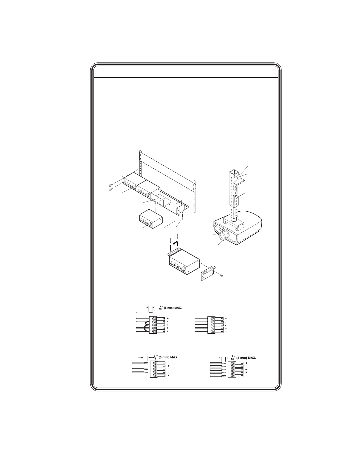
Step 1
Turn all of the equipment off and disconnect the power cords.
Step 2
Mount the RAC 104 (if applicable) or affix the rubber feet to the
bottom of the unit for tabletop use. See
A
A
U
D
I
O
C
O
B
N
1
T
R
O
L
2
S
A
D
J
U
S
3
T
M
E
4
N
T
S
V
o
l
.
B
a
V
s
O
s
L
T
r
U
e
b
M
l
e
E
&
T
O
N
E
C
O
N
T
R
O
L
L
E
R
A
A
U
D
I
O
C
O
B
N
1
T
R
O
L
2
S
A
D
J
U
S
3
T
M
E
4
N
T
S
V
o
l
.
B
a
1U Rack Shelf
1/4 Rack Width False Front
Use 2 mounting holes on
Face Plate
opposite corners.
page 2-2.
V
s
O
s
L
T
r
U
e
b
M
l
e
E
&
T
O
N
E
C
O
N
T
R
O
L
L
E
R
A
A
U
D
I
O
C
O
B
N
1
T
R
O
L
2
S
A
D
J
U
S
3
T
M
E
4
N
T
S
V
o
l
.
B
a
V
s
O
s
L
T
r
U
e
b
M
l
e
E
&
T
O
N
E
C
O
N
T
R
O
L
L
E
R
(2) 4-40 x 3/16" Screws
A
A
U
D
I
O
C
O
B
N
1
T
R
O
L
2
S
A
D
J
U
S
3
T
M
E
4
N
T
S
V
o
l
.
B
a
V
s
O
s
L
T
r
U
e
b
M
l
e
E
&
T
O
N
E
C
O
N
T
R
O
L
L
E
R
Step 3
Attach the cables to the audio input and output devices. Wire the
connectors as shown below.
Sleeve
Sleeve
Tip
Tip
LR
Unbalanced Input
Tip
No Ground here
Sleeve (s)
Tip
No Ground here
Unbalanced Output
Tip
Ring
Sleeve (s)
Tip
Ring
Balanced Input
LR
Ring
Sleeve (s)
Ring
Tip
Tip
Balanced Output
RAC 104 • Quick Start Guide
LR
LR
QS-1
Page 6
Quick Start Guide — RAC 104, cont’d
Step 4
If the RAC 104 is to be connected to a computer or host controller for
remote control, connect the host’s RS-232 cable to the RAC 104’s
3-pole captive screw RS-232 connector. Wire the connector as shown
below. See chapter 3 for more information on remote control.
Pin
Transmit (Tx)
Receive (Rx)
Ground (Gnd, )
RS-232
Tx Rx
RS-232 function Description
1 Tx Transmit data
2 Rx Receive data
3 Gnd Signal ground
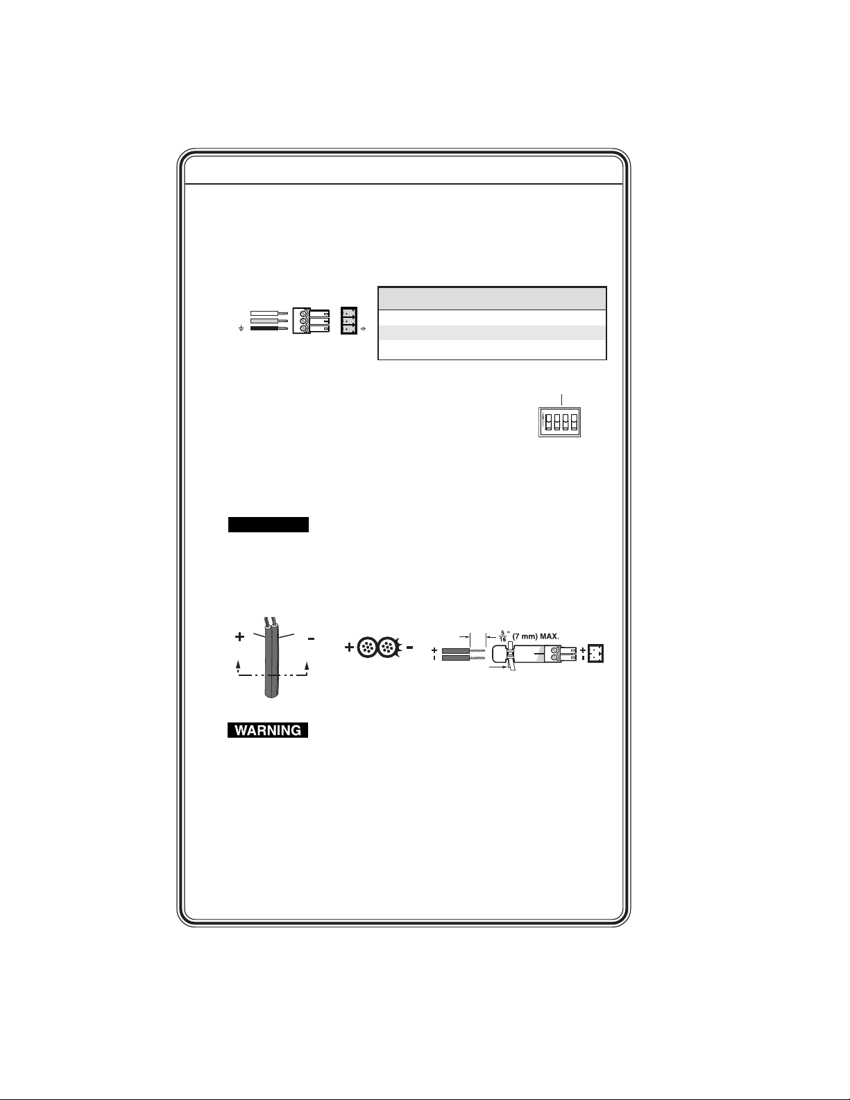
Step 5
Set the line level selector DIP switches to -10 dBV
(unbalanced, consumer line level) or +4 dBu (balanced,
professional line level).
Step 6
Connect power cords. Wire the RAC 104’s power connector as
shown below.
CAUTION
When connecting the power supply, voltage polarity is
extremely important. Applying power with incorrect
voltage polarity could damage the power supply and the
RAC 104. Identify the power cord negative lead by the
ridges on the side of the cord or a black heat shrink
wrapping around it.
Smooth
Ridges
AA
SECTION A–A
Power Supply
Output Cord
Tie Wrap
Orange Captive Screw
Connector
The two power cord wires must be kept separate while the
power supply is plugged in. Remove power before
wiring.
Step 7
Turn all the equipment on.
IN
OUT
A B A B
ON
LINE LEVEL
+4 dBu
-10 dBV
QS-2
Step 8
Set volume, bass, and treble levels using the front panel controls,
Simple Instruction Set commands, or the Extron Audio Products
Control Program. See chapters 2 and 3 for more information.
RAC 104 • Quick Start Guide
Page 7

Table of Contents
Chapter 1 • Introduction .......................................................... 1-1
About the RAC 104 ................................................................ 1-2
Features ...................................................................................... 1-2
Chapter 2 • Installation and Operation.......................... 2-1
Mounting the RAC 104 ........................................................2-2
UL rack mounting guidelines .................................................2-2
Tabletop use ...........................................................................2-3
Rack mounting ....................................................................... 2-3
Furniture mounting ............................................................... 2-4
Projector mounting ................................................................2-5
Rear Panel Features and Cabling ..................................2-6
Front Panel Controls............................................................. 2-9
Channel ties ..........................................................................2-10
Creating a tie ................................................................. 2-10
Cancelling a tie ............................................................... 2-11
Resetting the RAC 104 .........................................................2-11
Locking the front panel ....................................................... 2-11
Chapter 3 • Remote Control ................................................... 3-1
Simple Instruction Set ........................................................ 3-2
Host-to-controller instructions .............................................. 3-2
Controller-initiated messages ............................................... 3-2
Controller error responses .................................................... 3-3
Using the command/response table ..................................... 3-3
Command/response table for SIS commands ....................... 3-5
Windows-Based Program Control ................................ 3-10
Installing the software ........................................................ 3-10
Using the software ..............................................................3-10
Input/Output Level fields ............................................... 3-11
Preset Preview button ................................................... 3-11
Setting volume and tone limits .....................................3-11
Using the help system ......................................................... 3-12
Updating the firmware .......................................................3-12
Front Panel Security Lockout (Executive
Modes) ....................................................................................... 3-13
Presets ....................................................................................... 3-13
Mute ........................................................................................... 3-13
TOC-iRAC 104 • Table of Contents
Page 8

Table of Contents, cont’d
Appendix A • Specifications, Part Numbers,
and Accessories.............................................................................. A-1
Specifications ......................................................................... A-2
Included Parts ......................................................................... A-4
Accessories .............................................................................. A-4
All trademarks mentioned in this manual are the properties of their respective
owners.
68-782-01 Rev. C
vi
TOC-ii
RAC 104 • Table of Contents
12 08
Page 9

RAC 104
Chapter One
1
Introduction
About the RAC 104
Features
Page 10

Introduction
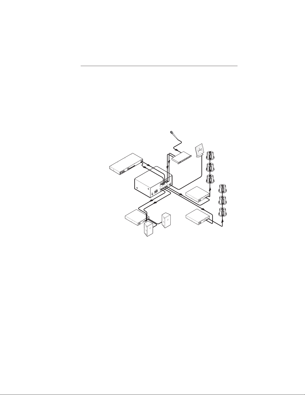
About the RAC 104
The Extron RAC 104 is a high-performance, four-channel
remote audio controller that adjusts volume and tone for stereo
or mono audio signals. Adjustments are made via the
RAC 104’s front panel controls or through a device connected to
the unit’s RS-232 connector.
The four channels on the RAC 104 can be used as four discrete
mono channels or can be tied into pairs as stereo channels. All
channels input and output balanced or unbalanced signals on
5-pole captive screw connectors.
The unit features smooth volume adjustment and three presets
for each channel. An external 100-240 VAC power supply is
included with the unit.
Features
Volume, bass, and treble controls — Adjust these three settings
using the RAC 104’s front panel controls or an RS-232
device. Set upper and lower limits for volume and tone
using an RS-232 device.
Four discrete channels — Versatile input/output configuration
can accommodate mono audio, stereo audio, or a
combination of the two.
Speed-sensitive volume knob — Turn the knob quickly to
make coarse adjustments or slowly to make fine
adjustments.
Smooth volume adjustment — No audible “stairstepping” or
jumps when volume is adjusted.
Input gain adjustment — Using an RS-232 device, adjust the
input gain to reduce variations in volume between
channels and set an upper volume limit for each channel.
Presets — Save and recall up to three presets for each channel
via an RS-232 device. Each preset saves volume, bass,
treble, and input gain settings.
Balanced/unbalanced inputs and outputs — The RAC 104 is
compatible with both balanced and unbalanced audio,
and can be used as a balanced-to-unbalanced audio
converter.
1-2
RAC 104 • Introduction
Page 11
Consumer and professional audio compatibility — Input and
C
U
S
C
U
S
C
U
S
output line level can be set to consumer (-10 dBV) or
professional (+4 dBu).
Rack, furniture, and projector mountability — The RAC 104
can be mounted on an optional VersaTools or Universal
rack shelf. Alternatively, it can be mounted under a desk,
podium, or other furniture, or secured to a projector
mount with optional brackets.
Extron
SI 26CT
Two -Wa y
Ceiling
Speakers
Zone 2
HPA 1001-70V
CLASS 2 WIRING
OUTPUT
70V
EMOTE
R
0W
L/MUTE
10
O
V
10V
INPUTS
R
DBY
STAN
NO)
HFP
O
(M
z
L
H
80
LISTED 17TT
DIO/VIDEO
U
A
LEVEL
APPARATUS
US
0
LIMITER/
-60Hz
0
5
,
PROTECT
A
1.3
SIGNAL
0V
100-24
HPA 1001-70V
CLASS 2 WIRING
OUTPUT
70V
REMOTE
100W
OL/MUTE
V
10V
INPUTS
R
BY
)
STAND
HFP
(MONO
L
Hz
0
8
LISTED 17TT
AUDIO/VIDEO
LEVEL
APPARATUS
US
0
LIMITER/
-60Hz
PROTECT
SIGNAL
100-240V 1.3A, 50
Extron
HPA 1001-70V
Audio Power
Amplifier
Extron
SI 26CT
Two -Wa y
Ceiling
Speakers
Zone 1
REMOTE
W 6AV
S
L
OUTPUTS
R
A
L
R
6
L
R
5
L
4
LR
INPUTS
3
LR
R
2
SYNC
L
R
1
IN
L
OUTPUTS
OUT
A
B
TED
S
LI
.
1T23
5
T.E
.
I
INPUTS
U S
6
C
3
3A
.
4
0
1
0-240V
0
1
2
z
0H
6
05
Extron
RAC 104
Volume and Tone
Controller
0Hz
, 50-6
A
PROTECT
1.3
0V
24
-
Extron
HPA 502
Audio Power
Amplifier
100
Extron
SW 6AV
Switcher
R
B
HPA 502
RING
UT
2
CLASS 2 WI
OUTP
1
2
50W x
REMOTE
MUTE
OHM
/8
VOL/
4
V
0
1
INPUTS
2
STANDBY
1
LISTED 17TT
2
LEVEL
UDIO/VIDEO
A
APPARATUS
US
1
0
2
0
1
LIMITER/
SIGNAL
Microphone
A
1
A
1
RAC 104
OUT
B
A
IN
+4 dBu
B
A
-10 dBV
ON
POWER
LINE LEVEL
12V
0.2A MAX
Extron
SI 28
Surface-Mount
Speakers
INPUTS
4
B
Rx
Tx
3
2
4
B
RS-232
3
2
OUTPUTS
Extron
HPA 1001-70V
Audio Power
Amplifier
Mixer
RS-232
Control
Typical RAC 104 application
RAC 104 • Introduction
1-3
Page 12

Introduction, cont’d
1-4
RAC 104 • Introduction
Page 13

RAC 104
Chapter Two
2
Installation and Operation
Mounting the RAC 104
Rear Panel Features and Cabling
Front Panel Controls
Page 14

Installation and Operation
Mounting the RAC 104
The RAC 104 can be set on a table or mounted on a rack shelf,
under a desk or tabletop, or on a projector mount.
UL rack mounting guidelines
The following Underwriters Laboratories (UL) guidelines
pertain to the safe installation of the RAC 104 in a rack.
1. Elevated operating ambient temperature — If installed in
a closed or multi-unit rack assembly, the operating
ambient temperature of the rack environment may be
greater than room ambient temperature. Therefore,
install the RAC 104 in an environment compatible with the
maximum ambient temperature (Tma = +122 °F, +50 °C)
specified by Extron.
2. Reduced air flow — Install the equipment in a rack so that
the amount of air flow required for safe operation of the
equipment is not compromised.
3. Mechanical loading — Mount the equipment in the rack
so that a hazardous condition is not achieved due to
uneven mechanical loading.
4. Circuit overloading — Connect the equipment to the
supply circuit and consider the effect that circuit
overloading might have on overcurrent protection and
supply wiring. Appropriate consideration of equipment
nameplate ratings should be used when addressing this
concern.
5. Reliable earthing (grounding) — Maintain reliable
grounding of rack-mounted equipment. Pay particular
attention to supply connections other than direct
connections to the branch circuit (e.g. use of power strips).
2-2
RAC 104 • Installation and Operation
Page 15

Tabletop use
Four self-adhesive rubber feet are included with the RAC 104.
For tabletop use, attach one foot at each corner of the bottom
side of the unit and place the unit in the desired location.
Rack mounting
For optional rack mounting, do not install the rubber feet.
Mount the RAC 104 on an RSF 123 VersaTools™ 19" 1U rack shelf
(Extron part #60-190-20) or a RSU 129 universal 1U rack shelf
(Extron part #60-190-01). On the Universal rack shelf, the unit
mounts in one of four locations to the rear of the rack or in one
of four locations to the front of the rack.
1. Remove rubber feet if they were previously installed on
the bottom of the RAC 104.
2. Mount the unit on the rack shelf, using two 4-40 x 3/16"
screws in opposite (diagonal) corners to secure the unit to
the shelf.
3. Install blank panel(s) or other unit(s) on the rack shelf.
4. Attach the rack shelf to the rack using the supplied bolts.
A
A
U
D
IO
C
O
B
N
1
T
R
O
L
2
S
A
D
J
U
S
3
T
M
E
4
N
T
S
V
o
l
.
B
a
V
s
O
s
L
T
r
U
e
b
M
le
E
&
T
O
N
E
C
O
N
T
R
O
L
L
E
R
A
A
U
D
IO
C
O
B
N
1
T
R
O
L
2
S
A
D
J
U
S
3
T
M
E
4
N
T
S
V
o
l
.
B
a
1U Rack Shelf
V
s
O
s
L
T
r
U
e
b
M
l
e
E
&
T
O
NE
C
O
N
T
R
O
L
L
E
R
1/4 Rack Width False Front
Face Plate
A
A
U
D
IO
C
O
B
N
1
T
R
O
L
2
S
A
D
J
U
S
3
T
M
E
4
N
T
S
V
o
l
.
B
a
V
s
O
s
L
Use 2 mounting holes on
opposite corners.
T
reb
U
M
le
E
&
T
O
N
E
C
O
N
T
R
O
L
L
E
R
(2) 4-40 x 3/16" Screws
Mounting the RAC 104 on a VersaTools rack shelf
Only products in the VersaTools line can be mounted on
a VersaTools shelf. Most 1U rack-mountable Extron
products can be mounted on the standard shelf.
RAC 104 • Installation and Operation 2-3
Page 16

Installation and Operation, cont’d
Furniture mounting
Furniture mount the RAC 104 using the optional MBU 123
mounting kit (Extron part #70-212-01) as follows:
1. Remove rubber feet if they were previously installed on
the bottom of the RAC 104.
2. Attach the furniture mounting brackets to the RAC 104
with the machine screws provided.
3. Hold the RAC 104 with the attached brackets against the
underside of the table or other furniture. Mark the
location of the screw holes of the bracket on the mounting
surface.
4. Drill 3/32" (2 mm) diameter pilot holes, 1/4" (6.3 mm)
deep in the mounting surface at the marked screw
locations.
5. Insert #8 wood screws into the four pilot holes. Tighten
each screw into the mounting surface until just less than
1/4" of the screw protrudes.
6. Align the mounting screws with the slots in the brackets
and place the RAC 104 against the surface, with the screws
through the bracket slots. See the illustration below.
7. Slide the RAC 104 slightly forward or back, then tighten all
four screws to secure the unit in place.
2-4
A
A
U
D
I
O
C
O
B
N
1
T
R
O
L
2
S
A
D
J
U
S
3
T
M
E
4
N
T
S
V
o
l
.
B
a
V
s
O
s
L
T
r
U
e
b
M
l
e
E
&
T
O
N
E
C
O
N
T
R
O
L
L
E
R
Mounting the RAC 104 under furniture
RAC 104 • Installation and Operation
Page 17

Projector mounting
Projector mount the RAC 104 using the optional PMK 100 pole
mount kit (part #70-217-01) as follows:
1. Remove rubber feet if they were previously installed on
the bottom of the RAC 104.
2. Attach the projector mounting brackets to the RAC 104
with the machine screws provided.
3. Secure the RAC 104 to a projector mount or other surface
by inserting the mounting bolt through the bracket’s
slotted hole, as shown below.
Rx
Tx
RS-232
B
34
B
INPUTS
34
2
2
A
1
A
OUTPUTS
1
+4 dBu
B
-10 dBV
OUT
A
IN
AB
ON
LINE LEVEL
RAC 104
POWER
12V
0.2A MAX
Projector
Mounting
Bracket
Mounting
Bolt
Digital Projector
Mounting the RAC 104 on a projector mount
RAC 104 • Installation and Operation 2-5
Page 18

Installation and Operation, cont’d
Rear Panel Features and Cabling
1
RAC 104
POWER
12V
0.2A MAX
5
OUT
IN
A B A B
ON
LINE LEVEL
+4 dBu
-10 dBV
4
Input connectors — Plug the audio input devices into these two
1
INPUTS
12B34
A
12B34
A
OUTPUTS
2
Tx Rx
3
RS-232
5-pole captive screw connectors. One stereo device or two mono
devices can be connected to each captive screw connector. Wire
the connectors as shown below.
Sleeve
Sleeve
Tip
Tip
LR
Unbalanced Input
Output connectors — Plug the audio output devices into these
2
Tip
Ring
Sleeve (s)
Tip
Ring
Balanced Input
LR
two 5-pole captive screw connectors. One stereo device or two
mono devices can be connected to each captive screw connector.
Wire the connectors as shown below.
2-6
Tip
No Ground here
Sleeve (s)
Tip
No Ground here
Unbalanced Output
CAUTION
LR
Connect the sleeve to ground ( ). Connecting the
Tip
Ring
Sleeve (s)
Tip
Ring
Balanced Output
sleeve to a negative (-) terminal will damage the
audio output circuits.
RAC 104 • Installation and Operation
LR
Page 19

RS-232 connector — Plug an optional RS-232 device into this
3
3-pole captive screw connector. Wire the connector as shown
below.
Transmit (Tx)
Receive (Rx)
Ground (Gnd, )
Pin
RS-232 function Description
RS-232
Tx Rx
1 Tx Transmit data
2 Rx Receive data
3 Gnd Signal ground
Line level selector DIP switches — Set these switches to
4
-10 dBV (unbalanced, consumer line level) or +4 dBu (balanced,
professional line level). There are four switches, one for each
input group and output group.
IN
OUT
A B A B
ON
LINE LEVEL
Power connector — An external 12 V power supply is included
5
+4 dBu
-10 dBV
with the unit. Plug it into this 2-pole captive screw connector.
Wire the connector as shown below.
Smooth
Ridges
Power Supply
Output Cord
CAUTION
AA
SECTION A–A
When connecting the power supply, voltage
Tie Wrap
Orange Captive Screw
Connector
polarity is extremely important. Applying power
with incorrect voltage polarity could damage the
power supply and the RAC 104. Identify the power
cord negative (ground) lead by the ridges on the
side of the cord or a black heat shrink wrapping
around it.
The two power cord wires must be kept separate
while the power supply is plugged in. Remove
power before wiring.
To verify the polarity before connection, check the no load
power supply output with a voltmeter.
RAC 104 • Installation and Operation 2-7
Page 20

Installation and Operation, cont’d
Your RAC 104 may have shipped with a blue captive
screw connector. This blue connector can be plugged
into either a blue or an orange power receptacle.
The ideal length of exposed (stripped) copper wire
for the blue connector is 3/16" (5 mm).
The blue connector does not have the extended tail or the
included tie-wrap.
Do not tin the power supply leads before installing in the
direct insertion connector. Tinned wires are not as
secure in the connectors and could be pulled out.
After making any adjustments to the RAC 104, either
via the front panel controls, SIS commands, or the
Extron Audio Products Control Program, wait at least
10 seconds after making those changes before
disconnecting power to the RAC 104. Failure to
observe the 10-second timeout may result in those
adjustments not being saved.
2-8
RAC 104 • Installation and Operation
Page 21

Front Panel Controls
VOLUME & TONE CONTROLLER
1
2
3
4
BASS
TREBLE
VOL
ADJUSTMENTS
AUDIO CONTROLS
A
B
RAC 104
2
3
1
4
Power LED — Lights to indicate that the RAC 104 is on.
1
Channel selector buttons and LEDs — The RAC 104 has two
2
channel selector buttons, one for channel group A (channels 1
and 2) and one for channel group B (channels 3 and 4). Press
and release these buttons to select the channel(s) to adjust.
When a channel is selected, the corresponding LED lights.
Pressing the buttons repeatedly cycles through four possible
selections:
Both LEDs on — both channels selected (tied, for stereo audio)
When both channels in a group are selected, they will be
tied togther once the user turns the adjustment knob.
The RAC 104 automatically sets both channels to the
same volume and tone levels and any future changes
will affect both channels simultaneously. To cancel a tie,
press and release the channel selector button again and
then turn the adjustment knob. See “Channel ties” in
this chapter for more information.
LED 1 (or 3) on — mono channel 1 (or 3) or the left stereo
channel selected
LED 2 (or 4) on — mono channel 2 (or 4) or the right stereo
channel selected
Both LEDs off — no channel selected
Groups A and B cannot be adjusted at the same time.
Pressing the button for one group will cause the LEDs
for the other group to turn off.
RAC 104 • Installation and Operation
2-9
Page 22

Installation and Operation, cont’d
Adjustment selector button and LEDs — Press and release this
3
button to select volume, bass, or treble adjustment. When an
adjustment is selected, the corresponding LED lights. If after 10
seconds you do not make any other adjustments or selections on
the front panel, this selector will default to volume.
The adjustment selector button will not function unless
you have first selected one or more channels (see
above).
Adjustment knob — Turn this knob to adjust the volume, bass,
4
or treble for the channel(s) you selected using the channel
selector buttons. When you reach the upper or lower limit of
the allowable adjustment range, the adjustment selector LED
flashes three times. (See chapter 3, “Remote Control”, for
instructions on setting volume and tone limits.)
The volume adjustment is speed sensitive. Turn the
knob quickly to make coarse volume adjustments or
slowly to make fine volume adjustments.
Channel ties
The user can tie the two channels in a group together for stereo
audio.
Creating a tie
To tie channels together:
1. Press the channel selector button until both LEDs are on.
2. Press the adjustment selector button to select either
volume, bass, or treble and turn the adjustment knob in
either direction.
The RAC 104 automatically sets both channels to the same
volume or tone level using the following criteria:
For volume — The unit changes the volume setting for the
channel with the highest volume to match that of the other
channel.
For example, if the volume on channel 1 is set to 85 and
the volume on channel 2 is set to 50, the unit will change
channel 1’s volume setting to 50 when the user ties them
together.
Volume before tie: 85 50
Volume after tie: 50 50
Channel 1 Channel 2
2
,
2-10
For bass and treble — The unit changes the tone setting
for the channel with the tone setting farthest from 7 (0dB)
to match that of the other channel.
RAC 104 • Installation and Operation
Page 23

For example, if the treble on channel 1 is set to 6 and the
treble on channel 2 is set to 10, the unit will change
channel 2’s treble setting to 6 when the user ties them
together.
Channel 1 Channel 2
Treble before tie: 6 10
Treble after tie: 6 6
Volume, bass, treble, and mute adjustments can now be made
to both channels simultaneously. The user can continue to
adjust the gain settings independently using the SIS or the
Windows-based control program via the RS-232 connector (see
chapter 3 for more information).
Ties can also be made using the SIS or the Windows-based
control program (see chapter 3 for more information).
Cancelling a tie
To cancel a tie, press and release the channel selector button
again so that only one channel selector LED is on, then turn the
knob.
Ties can also be cancelled using the SIS or the Windows-based
control program (see chapter 3 for more information).
Resetting the RAC 104
To return the RAC 104 to its default settings, press and hold the
adjustment selector button for 10 seconds. All the LEDs will
light and then turn off. The default settings are:
Volume 70 (-30 dB)
Gain 0 dB
Bass 7 (0 dB)
Treble 7 (0 dB)
Any volume and tone limits are cancelled (see chapter 3 for
information on limits).
The unit can also be reset using the SIS or the Windows-based
control program (see chapter 3 for more information).
Locking the front panel
To prevent accidental changes to the controller settings, the
front panel controls can be locked using one of two executive
modes. The user turns the executive modes on and off using
either the SIS or the Windows-based control program via the
RS-232 connector (see chapter 3 for more information).
If the user presses a front panel button that is locked, the LED
corresponding to that button flashes three times.
RAC 104 • Installation and Operation
2-11
Page 24

Installation and Operation, cont’d
2-12
RAC 104 • Installation and Operation
Page 25

RAC 104
Chapter Three
3
Remote Control
Simple Instruction Set
Windows-Based Program Control
Front Panel Security Lock Out (Executive Modes)
Presets
Mute
Page 26

Remote Control
The RAC 104 can be controlled remotely via the RS-232
connector using the Extron Simple Instruction Set (SIS) or the
Extron Windows-based control program.
The RS-232 connector on the RAC 104 is a 3-pole captive screw
connector, with one pole for transmitting data, one for receiving
data, and one for the ground. Wire the RS-232 connector as
shown below.
Transmit (Tx)
Receive (Rx)
Ground (Gnd, )
RS-232 connector wiring
Pin
RS-232 function Description
1 Tx Transmit data
2 Rx Receive data
3 Gnd Signal ground
RS-232 pin assignment table
The RS-232 protocol for this connector is 9600 baud, 8-bit, 1 stop
bit, no parity.
RS-232
Tx Rx
Simple Instruction Set
Host-to-controller instructions
The RAC 104 accepts SIS commands through the RS-232 port.
SIS commands consist of one or more characters per command
field. They do not require any special characters to begin or
end the command character sequence. Each controller response
to an SIS command ends with a carriage return and a line feed
(CR/LF = ), which signals the end of the response character
string. A string is one or more characters.
Controller-initiated messages
The following copyright message is initiated by the controller
when it is first powered on. Vx.xx is the firmware version
number.
Boot V1.00,(c) 2003, ? to Enter
(c) Copyright 2003,Extron Electronics,RAC 104, Vx.xx
RAC 104 • Remote Control
3-2
Page 27

Controller error responses
When the RAC 104 receives an SIS command and determines
that it is valid, it performs the command and sends a response
to the host device. If the controller is unable to perform the
command because the command is invalid or contains invalid
parameters, the contoller returns an error response to the host.
The error response codes are:
E01 — Invalid channel number (too large)
E10 — Invalid command
E13 — Invalid value (out of range)
E14 — Invalid setting at this time (i.e., setting outside the
upper or lower value limit)
E23 — Firmware update failure
Using the command/response table
The command/response table begins on the next page. Upper
and lower case letters can be used interchangeably in the
command field except where noted. Symbols are used
throughout the table to represent variables in the command/
response fields. An ASCII-to-hexadecimal (HEX) conversion
table and symbol definitions are provided below. Command
and response examples are shown throughout the table.
ASCII to HEX Conversion Table
•
Symbol definitions
= Carriage return/line feed
= Carriage return (no line feed)
= 0 through 100, output volume; attenuation (dB) = X1-100.
X1
Default = 70 (-30 dB)
= 1 through 4, channel numbers
X2
1 = group A, channel 1
2 = group A, channel 2
RAC 104 • Remote Control
3-3
Page 28

Remote Control, cont’d
3 = group B, channel 3
4 = group B, channel 4
= 0 or 1
X3
0 = off
1 = on
= 0 through 14, bass adjustment range
X4
(+/-14 dB; 2 dB increment/decrement,
bass in dB = [bass number minus 7] times 2;
default = 7 [0 dB]).
= 0 through 14, treble adjustment range
X5
(+/-14 dB; 2 dB increment/decrement,
treble in dB = [treble number minus 7] times 2;
default = 7 [0 dB]).
= Front panel executive modes
X6
0 = off
1 = executive mode 1
2 = executive mode 2
= Controller software version to second decimal place
X7
= A or B, group number
X8
Group A = channels 1 and 2
Group B = channels 3 and 4
= 1 through 3, preset number
X9
= -12 through +12 (audio gain or attenuation in dB)
X10
= 0 through 12 (audio gain in dB)
X11
= 1 through 12 (audio attenuation in dB)
X12
= 0 through 15, decimal number indicates settings for the
X13
four input and output line level DIP switches. DIP
switch settings are shown in the table below.
X13
DIP
Switch Group 0 1 2 3 4 5 6 7 8 9 10 11 12 13 14 15
1 Input A Off Off Off Off Off Off Off Off On On On On On On On On
2 Input B Off Off Off Off On On On On Off Off Off Off On On On On
3 Output A Off Off On On Off Off On On Off Off On On Off Off On On
4 Output B Off On Off On Off On Off On Off On Off On Off On Off On
Off = -10 dBV (unbalanced, consumer level)
On = +4 dBu (balanced, pro level)
3-4
RAC 104 • Remote Control
Page 29

.
X2
dB.
X10
by 1 dB.
to
X2
by 1 dB.
X2
X2
dB.
X10
to
X2
Set gain for channel
Set attenuation for channel
Increment gain for channel
Decrement gain for channel
View input gain/attenuation for channel
.
by 1 dB.
X2
by 1 dB.
.
X2
X2
X1
.
X2
to
X2
.
X2
.
X2
Set volume for channel
Increment volume for channel
Decrement volume for channel
View output volume for channel
Mute channel
Unmute channel
View mute status of channel
Mute all channels.
Unmute all channels.
View mute status of all channels.
Channels 1 & 3 muted, channels 2 & 4 not muted
X10
X10
Gain
X2
g Chn
X12
*
X2
X10
Gain
X2
X2
+G/g Chn
X2
X2
Gain
X10
X2
-G/g Chn
G/g
X1
X1
X1
*
*
*
X2
X2
X2
V/v Vol
X1
+V/v Vol
-V/v Vol
*
X2
X2
X2
X10
Gain
X2
G Chn
X11
*
(host to RAC 104) (RAC 104 to host)
X2
Example: 3*8G Chn3 Gain8 Set gain for channel 3 to 8 dB.
Set gain (+dB)
Command/response table for SIS commands
Command ASCII Command Response Additional description
Audio input gain/attenuation
Set attenuation (-dB)
View gain/attenuation for input V/v
Gain decrement
Gain increment
Specify volume level
Increment volume
Output Volume
Decrement volume
X3
*
X2
X1
V/v
X2
View volume
*1Z/z Amt
X2
Mute one channel
Mute
X3
•
X3
X3
X3
*
X2
*0Z/z Amt
X2
X3
Z/z
X2
X3
•
X3
•
X3
Example: Z 1 0 1 0
Unmute all channels 0*Z/z Amt All*
View mute status of one channel
Unmute one channel
View mute status of all channels Z/z
Mute all channels 1*Z/z Amt All*
RAC 104 • Remote Control
3-5
Page 30

Remote Control, cont’d
by 2 dB.
by 2dB.
by 2 dB.
.
X2
X2
X4
to
X2
Set bass level for channel
X4
.
X2
Increment bass level for channel
Decrement bass level for channel
View bass level for channel
X4
X4
X4
by 2 dB.
.
X2
X2
X5
to
X2
Set treble level for channel
X5
.
X2
Increment treble level for channel
Decrement treble level for channel
View treble level for channel
X5
X5
X5
; see note below.
X2
.
.
X2
X2
for channel
for channel
X9
X9
Save preset
Recall preset
View preset status for channel
and preset 3 is used.
X3
X9
X9
•
*
*
X3
X2
X2
•
X3
> Bas
X4
+> Bas
-> Bas
*
(host to RAC 104) (RAC 104 to host)
Command ASCII Command Response Additional description
3-6
X2
Specify bass level
Bass adjustment
RAC 104 • Remote Control
>
X2
X2
X2
Increment bass level
Decrement bass level
View bass level
<Trb
X5
+< Trb
-< Trb
*
X2
Specify treble level
Treble adjustment
<
X2
X2
X2
Increment treble level
View treble level
Decrement treble level
, Spr
. Rpr
X9
X9
*
*
.
X2
X2
X2
Each of the four channels has three presets. The View Preset command response tells the user which presets for
a particular channel have been used to save settings and which are empty. The response consists of a sequence
Example 3. 0 1 1 For channel 3, preset 1 is empty, preset 2 is used,
Save preset
Recall preset
Preset save and recall
View preset status
of three digits. The first, second, and third digits indicate the status of presets 1, 2, and 3, respectively. A 0 in
the sequence indicates an empty preset, a 1 indicates a used preset.
Page 31

X10
= 0
= 70
X1
= 7
X4
response once the
Upload command.
Esc
= 7.
X5
X1
X10
X4
*5#
*6#
*7#
X9
X9
X9
*
*
*
X2
X2
(host to RAC 104) (RAC 104 to host)
X2
X5
*8#
X9
*
X2
Input gain
Bass level
Treble level
Volume level
ZXXX Zpx Default settings:
Esc
Upload Go See note below.
Esc
See note below.
response, select Send Text File from the Transfer menu. In the Send Text File window,
Firmware updates will periodically become available on the Extron Web site. To update the firmware, first
download the update file from the site. Then open HyperTerminal and type the
After receiving the Go
locate and select the file you downloaded and click Open. The controller will send the UPL
update has been successfully completed. It will send the error code E23 if the update failed.
View input gain
View output volume
View bass setting
Command ASCII Command Response Additional description
View Preset Settings
View treble setting
Reset to factory defaults
System reset
RAC 104 • Remote Control
Upload firmware update
Upload success UPL
Update firmware
3-7
Page 32

Remote Control, cont’d
0 = off.
1 = mode 1 (all features except volume are locked).
2 = mode 2 (all features are locked).
0 = off.
1 = mode 1.
2 = mode 2.
X6
X6
View DIP switch settings (see table on page 3-4).
60-561-01.
X13
together
X8
Tie channels in group
Group A tied/not tied, group B tied/not tied.
(0 = not tied, 1= tied).
X3
X3
*
GrpB*
X8
X3
X7
X/x Exe
(host to RAC 104) (RAC 104 to host)
Command ASCII Command Response Additional description
3-8
X6
Set executive mode
Front panel lock out (Executive modes)
View executive mode status X/x
RAC 104 • Remote Control
*4# Tie Grp
X3
*
I/i
X8
Commands can be made back-to-back with no spaces. Example 1*1!02!03*03!..
Information request (DIP switch settings)
Request for part number N/n xx-xxx-xx
Information requests
Query software version Q/q
Tie channels together
Tie channels together
View ties of all groups 4# GrpA*
The RAC 104 supports the 2-digit numeric format (01*02).
Page 33

.
.
X2
X2
.
.
X1
X1
to
to
X2
X2
Set volume lower limit for channel
Set volume upper limit for channel
.
X1
to
X2
View volume lower limit setting for channel
View volume upper limit setting for channel
Set bass lower limit for channel
.
X2
.
X2
.
X1
to
X2
Set bass upper limit for channel
View bass lower limit setting for channel
View bass upper limit limit setting for channel
.
X2
.
.
X1
X1
to
to
X2
X2
Set treble lower limit for channel
Set treble upper limit for channel
View treble lower limit setting for channel
.
X2
View treble upper limit setting for channel
X1
X1
*
*
X2
X2
X1
* 21 # Vll
* 22 # Vul
X1
X1
*
*
* 21 #
X2
X2
(host to RAC 104) (RAC 104 to host)
Command ASCII Command Response Additional description
Volume, Bass, and Treble Range Limit Settings
X2
Set volume lower limit
View volume lower limit
Set volume upper limit
X4
X4
*
*
X2
X2
X1
* 23 # Bll
* 24 # Bul
X4
X4
* 22 #
*
*
X2
X2
X2
Set bass upper limit
Set bass lower limit
View volume upper limit
X5
X5
*
*
X2
X2
X4
X4
* 23 #
* 24 #
X2
X2
View bass lower limit
View bass upper limit
X5
X5
* 25 # Tll
* 26 # Tul
X5
X5
*
*
* 25 #
X2
Set treble lower limit
* 26 #
X2
X2
X2
View treble lower limit
Set treble upper limit
View treble upper limit
RAC 104 • Remote Control
3-9
Page 34

Remote Control, cont’d
Windows®-Based Program Control
The Windows-based Extron Audio Products Control Program is
compatible with Windows 2000 and Windows XP and provides
remote control of the volume, gain, and tone adjustment, and
other RAC 104 features.
Updates to this program can be downloaded from the Extron
Web site (http://www.extron.com).
Installing the software
The program is contained on the Extron Software Products
CD-ROM. To install the software:
1. Insert the CD-ROM into the drive. The installation
program should start automatically. If it does not selfstart, run Launch.exe from the CD.
2. The Extron software CD window appears.
Using the software
To run the software:
1. Double click the Audio Products Control Program icon in
the Extron Electronics program group.
2. Click the comm port that is connected to the unit’s remote
connector.
3. Click OK. The Audio Products Control Program main
window displays the current volume, tone, and gain/
attenuation settings for each channel and allows the user
to adjust them. The window also contains channel tie,
channel mute, front panel lock out (executive modes), and
preset controls.
3-10
Windows-based control program main window
RAC 104 • Remote Control
Page 35

Input/Output Level fields
The Input Level and Output Level fields display the current
settings for the line level selector DIP switches. See the chapter
2 section, “Rear Panel Features and Cabling”, for more
information.
Input/Output Level fields
Preset Preview button
To view a preset before recalling it, select a channel and preset
number, then click and hold the Preview button.
Preset Preview button
Setting volume and tone limits
Volume and tone limits allow you to specify the range of
allowable volume, bass, and treble values. To set upper and
lower volume and tone limits:
1. On the File menu, click Advanced Setup, then click Set
Limits. A check mark appears next to Set Limits.
2. In the Volume and Tone adjustment area of the main
window, click and drag the yellow arrows up or down to
change the upper and lower limits. Limits for channels
tied together will change simultaneously.
3. To lock the limits to the values you selected in step 2, click
Advanced Setup on the File menu, then click Set Limits.
The check mark next to Set Limits disappears.
RAC 104 • Remote Control
3-11
Page 36

Remote Control, cont’d
Using the help system
For information about program features, you can access the
help program in any of the following ways:
• From the Extron Electronics program group, double-click
the Audio Products Help icon.
• From within the Audio Products Control program, click
Help on the task bar.
• From within the Audio Products Control program, press
the F1 key.
Updating the firmware
Firmware updates will periodically become available on the
Extron Web site. To load a firmware update:
1. Download the update file from the Extron Web site
(www.extron.com).
2. Run the Audio Products Control Program.
3. On the File menu, click Update Firmware. The Firmware
Loader window appears.
3-12
Firmware Loader window
4. Click the Upload Firmware File button.
5. Locate and select the update file you downloaded from the
Web site and click Open. The Firmware Loader loads the
update.
The RAC 104’s front panel LEDs flash intermittently
during the loading process. Once loading is complete, all
the LEDs flash simultaneously for 10 seconds and then
return to their default settings.
The firmware update file must have an .s19 extension. If
it does not have that extension it will not work properly.
6. After the update has completed loading, click Exit.
RAC 104 • Remote Control
Page 37

Front Panel Security Lockout (Executive
Modes)
To prevent accidental changes to the controller settings, the
front panel controls can be locked using one of two executive
modes. The user turns the executive modes on and off using
either the SIS or the Windows-based control program via the
RS-232 connector. While an executive mode is on, the locked
controls can be adjusted through the RS-232 device only.
Executive mode 1 locks the tone controls and channel selector
buttons only. The user can continue to change the volume
via the front panel.
Executive mode 2 locks all the front panel controls.
Presets
The user can program up to three presets for each channel using
the SIS or the Windows-based control program via the RS-232
connector. The presets allow the user to save the current input
gain and output volume, bass, and treble settings for recall at a
later time.
When two channels are tied together, selecting a preset for
either channel will set the volume, bass, treble, and gain for
both channels. Input gain for tied channels can be adjusted
independently.
Mute
The user can mute each channel using the SIS or the
Windows-based control program via the RS-232 connector.
• Volume and tone settings can still be adjusted while a
channel is muted.
• When two channels are tied together, selecting mute or
unmute for one channel will mute or unmute both.
• When the user ties a muted channel to a channel that is not
muted, the RAC 104 unmutes the muted channel
automatically.
RAC 104 • Remote Control
3-13
Page 38

Remote Control, cont’d
3-14
RAC 104 • Remote Control
Page 39

RAC 104
Appendix A
A
Specifications, Part Numbers,
and Accessories
Specifications
Included Parts
Accessories
Page 40

Specifications, Part Numbers, and Accessories
Specifications
Audio
Gain................................................ Unbalanced output: -6 dB; balanced
output: 0 dB
when input gain is set to 0 dB, output
volume is at 100, and the input and output
are set to the same level via the Line Level
DIP switch
Frequency response .................... 20 Hz to 20 kHz, ±0.05 dB
THD + Noise................................. 0.03% @ 1 kHz at nominal level
S/N ............................................... >90 dB, balanced at maximum output
(unweighted)
Crosstalk ....................................... <-120 dB @ 1 kHz
Stereo channel separation .......... >80 dB @ 1 kHz, >60 dB @ 20 kHz
CMRR ............................................ >75 dB @ 1 kHz
Volume control range ................. -100 dB to 0 dB (volume numbers 0
through 100) in 0.5 dB steps
Attenuation = volume number minus 100. The default is -30 dB
= volume number 70.
Bass control range ....................... ±14 dB, 100 Hz referenced to 1 kHz
(0 through 14) in 2 dB steps
Bass dB = (bass number minus 7) times 2. The default is 0 dB =
bass number 7.
Treble control range .................... ±14 dB, 10 kHz referenced to 1 kHz
(0 through 14) in 2 dB steps
Treble dB = (treble number minus 7) times 2. The default is 0 dB
= treble number 7.
Audio input
Number/signal type ................... 4 channels, which can be mono or tied into
stereo pairs, balanced/unbalanced
Connectors ................................... (2) 3.5 mm captive screw connectors,
5 pole
Impedance .................................... >18k ohms unbalanced/balanced,
DC coupled
Nominal level ............................... +4 dBu (1.23 V), -10 dBV (316 mV),
switchable per group
Maximum level ............................ +20 dBu (7.75 V), (balanced or unbalanced)
at 1% THD+N
A-2
RAC 104 • Specifications, Part Numbers, and Accessories
Page 41

Input gain adjustment ................. –12 dB to +12 dB
0 dBu = 0.775 Vrms, 0 dBV = 1 Vrms, 0 dBV 2 dBu.
Audio output
Number/signal type ................... 4 channels, which can be mono or tied into
stereo pairs, balanced/unbalanced
Connectors ................................... (2) 3.5 mm captive screw connector, 5 pole
Impedance .................................... 50 ohms unbalanced, 100 ohms balanced
Nominal level ............................... +4 dBu (1.23 V), balanced; -10 dBV
(316 mV), unbalanced; switchable per
group
Maximum level (Hi-Z) ................ >+20 dBu, balanced or unbalanced at 1%
THD+N
Control/remote — remote volume/tone controller
Serial control port ........................ RS-232, 3.5 mm captive screw connector,
3 pole
Baud rate and protocol ............... 9600 baud, 8 data bits, 1 stop bit, no parity
Serial control pin configurations 1 = TX, 2 = RX, 3 = GND
Program control .......................... Extron’s control/configuration program
for Windows
®
Extron’s Simple Instruction Set (SIS™)
General
External power supply................ 100 VAC to 240 VAC, 50/60 Hz, external
to 12 VDC, 1 A, regulated
Power input requirements ......... 12 VDC, 0.2 A
Temperature/humidity .............. Storage: -40 to +158 °F (-40 to +70 °C) /
10% to 90%, noncondensing
Operating: +32 to +122 °F (0 to +50 °C) /
10% to 90%, noncondensing
Mounting
Rack mount ...................... Yes, with optional 1U, 9.5" deep rack shelf
(RSU 129, #60-190-01; RSB 129, 60-604-01);
1U, 6" deep rack shelf (RSU 126,
#60-190-10, RSB 126, 60-604-10); or
VersaTools
(RSF 123, #60-190-20, RSB 123, 60-604-20)
Furniture mount .............. Yes, with optional brackets
Enclosure type .............................. Metal
®
1U, 3.5" deep rack shelf
RAC 104 • Specifications, Part Numbers, and Accessories A-3
Page 42

Specifications, Part Numbers, Accessories, cont’d
Enclosure dimensions ................. 1.7" H x 4.3" W x 3.0" D (1U high, quarter
rack wide)
4.3 cm H x 10.9 cm W x 7.6 cm D
(Depth excludes connectors and knob.)
Product weight ............................. 0.5 lbs (0.3 kg)
Shipping weight ........................... 2 lbs (1 kg)
Vibration ....................................... ISTA 1A in carton (International Safe
Transit Association)
Regulatory compliance
Safety ................................. CE, CUL, UL
EMI/EMC ......................... CE, C-tick, FCC Class A, ICES, VCCI
MTBF ............................................. 30,000 hours
Warranty ....................................... 3 years parts and labor
All nominal levels are at ±10%.
Specifications are subject to change without notice.
Included Parts
These items are included in each order for an RAC 104:
Included parts Replacement
Part number
Accessories
A-4
RAC 104 • Specifications, Part Numbers, and Accessories
RAC 104 60-561-01
12 VDC, 1.0 A external power supply 70-055-01
3.5 mm, 5-pole captive screw connector (4) 10-319-10
3.5 mm, 3-pole captive screw connector (1) 10-265-03
Audio Products Control Program
Tweeker (small screwdriver)
User’s Manual
These items can be ordered separately:
Accessories Part number
RSU 129 1U universal rack shelf 60-190-01
RSF 123 VersaTools 1U rack shelf 60-190-20
MBU 123 under-desk mounting bracket 70-212-01
PMK 100 projector mounting bracket 70-217-01
Page 43

Extron’s Warranty
Extron Electronics warrants this product against defects in materials and workmanship
for a period of three years from the date of purchase. In the event of malfunction during
the warranty period attributable directly to faulty workmanship and/or materials,
Extron Electronics will, at its option, repair or replace said products or components,
to whatever extent it shall deem necessary to restore said product to proper operating
condition, provided that it is returned within the warranty period, with proof of
purchase and descripti
on of malfunction to:
USA, Canada, South America,
and Central America:
Extron USA
1001 East Ball Road
Anaheim, CA 92805
U.S.A.
Europe, Africa, and the Middle East:
Extron Europe
Hanzeboulevard 10
3825 PH Amersfoort
The Netherlands
Asia:
Extron Asia
135 Joo Seng Road #04-01
PM Industrial Bldg.
Singapore 368363
Singapore
This Limited Warranty does not apply if t
handling care, electrical or mechanical abuse, abnormal operating conditions or nonExtron authorized modifi cation to the product.
If it has been determined that the product is defective, please call Extron and ask for an
Applications Engineer at (714) 491-1500 (USA), 31.33.453.4040 (Europe), 65.6383.4400
(Asia), or 81.3.3511.7655 (Japan) to receive an RA# (Return Authorization number). This
will begin the repair process as quickly as possible.
Units must be returned insured, with shipping charges prepaid. If not insu
assume the risk of loss or damage during shipment. Returned units must include the
serial number and a description of the problem, as well as the name of the person to
contact in case there are any questions.
Extron Electronics makes no further warranties either expressed or i
to the product and its quality, performance, merchantability, or fi tness for any particular
use. In no event will Extron Electronics be liable for direct, indirect, or consequential
damages resulting from any defect in this product eve
advised of such damage.
Please note that laws vary from state to state and country to country, and that some
provisions of this warranty may not apply to you.
he fault has been caused by misuse, improper
Japan:
Extron Japan
Kyodo Building, 16 Ichi
Chiyoda-ku, Tokyo 102-0082
Japan
China:
Extron China
686 Ronghua Road
Songjiang District
Shanghai 201611
China
Middle East:
Extron Middle East
Dubai Airport Free Zone
F12, PO Box 293666
United Arab Emirates, Dubai
n if Extron Electronics has been
bancho
red, you
mplied with respect
Page 44

Extron USA - Wes t
Headquarters
+800.633.9876
Inside USA / Canada Only
+1.714.491.1500
+1.714.491.1517 FAX
Extron USA - Ea st
+800.633.9876
Inside USA / Canada Only
+1.9 19.8 63 .179 4
+1.9 19.8 63 .179 7 FAX
Extron Europe
+800.3987.6673
Inside Europe Only
+31.33.453.4040
+31.33.453.4050 FAX
Extron Asia
+800.7339.8766
Inside Asia Only
+65.6383.4400
+65.6383.4664 FA X
Extron Japan
+81.3.3511.7655
+81.3.3511.7656 FAX
© 2008 Extron Electronics. All rights reserved.
Extron China
+400.883.1568
Inside China Only
+86.21.3760.1568
+86.21.3760.1566 FAX
Extron Middle East
+971.4.2991800
+971.4.2991880 FAX
 Loading...