

Page 1

Quantum Ultra
Videowall Processing System
User Guide
Videowall Processors
68-2760-01 Rev. A
05 17
Page 2

Safety Instructions
Safety Instructions • English
WARNING: This symbol, , when used on the product, is intended to
alert the user of the presence of uninsulated dangerous voltage within
the product’s enclosure that may present a risk of electric shock.
ATTENTION: This symbol, , when used on the product, is intended
to alert the user of important operating and maintenance (servicing)
instructions in the literature provided with the equipment.
For information on safety guidelines, regulatory compliances, EMI/EMF
compatibility, accessibility, and related topics, see the Extron Safety and
Regulatory Compliance Guide, part number 68-290-01, on the Extron
website, www.extron.com.
Sicherheitsanweisungen • Deutsch
WARNUNG: Dieses Symbol auf dem Produkt soll den Benutzer
darauf aufmerksam machen, dass im Inneren des Gehäuses dieses
Produktes gefährliche Spannungen herrschen, die nicht isoliert sind und
die einen elektrischen Schlag verursachen können.
VORSICHT: Dieses Symbol auf dem Produkt soll dem Benutzer in
der im Lieferumfang enthaltenen Dokumentation besonders wichtige
Hinweise zur Bedienung und Wartung (Instandhaltung) geben.
Weitere Informationen über die Sicherheitsrichtlinien, Produkthandhabung,
EMI/EMF-Kompatibilität, Zugänglichkeit und verwandte Themen finden Sie in
den Extron-Richtlinien für Sicherheit und Handhabung (Artikelnummer
68-290-01) auf der Extron-Website, www.extron.com.
Instrucciones de seguridad • Español
ADVERTENCIA: Este símbolo, , cuando se utiliza en el producto,
avisa al usuario de la presencia de voltaje peligroso sin aislar dentro del
producto, lo que puede representar un riesgo de descarga eléctrica.
ATENCIÓN: Este símbolo, , cuando se utiliza en el producto, avisa
al usuario de la presencia de importantes instrucciones de uso y
mantenimiento recogidas en la documentación proporcionada con el
equipo.
Para obtener información sobre directrices de seguridad, cumplimiento
de normativas, compatibilidad electromagnética, accesibilidad y temas
relacionados, consulte la Guía de cumplimiento de normativas y seguridad
de Extron, referencia 68-290-01, en el sitio Web de Extron, www.extron.com.
Instructions de sécurité • Français
AVERTISSEMENT : Ce pictogramme, , lorsqu’il est utilisé sur le
produit, signale à l’utilisateur la présence à l’intérieur du boîtier du
produit d’une tension électrique dangereuse susceptible de provoquer
un choc électrique.
ATTENTION : Ce pictogramme, , lorsqu’il est utilisé sur le produit,
signale à l’utilisateur des instructions d’utilisation ou de maintenance
importantes qui se trouvent dans la documentation fournie avec le
matériel.
Pour en savoir plus sur les règles de sécurité, la conformité à la
réglementation, la compatibilité EMI/EMF, l’accessibilité, et autres sujets
connexes, lisez les informations de sécurité et de conformité Extron, réf.
68-290-01, sur le site Extron, www.extron.com.
Istruzioni di sicurezza • Italiano
AVVERTENZA: Il simbolo, , se usato sul prodotto, serve ad
avvertire l’utente della presenza di tensione non isolata pericolosa
all’interno del contenitore del prodotto che può costituire un rischio di
scosse elettriche.
ATTENTZIONE: Il simbolo, , se usato sul prodotto, serve ad
avvertire l’utente della presenza di importanti istruzioni di funzionamento
e manutenzione nella documentazione fornita con l’apparecchio.
Per informazioni su parametri di sicurezza, conformità alle normative,
compatibilità EMI/EMF, accessibilità e argomenti simili, fare riferimento
alla Guida alla conformità normativa e di sicurezza di Extron, cod. articolo
68-290-01, sul sito web di Extron, www.extron.com.
Instrukcje bezpieczeństwa • Polska
OSTRZEŻENIE: Ten symbol, , gdy używany na produkt, ma na celu
poinformować użytkownika o obecności izolowanego i niebezpiecznego
napięcia wewnątrz obudowy produktu, który może stanowić zagrożenie
porażenia prądem elektrycznym.
UWAGI: Ten symbol, , gdy używany na produkt, jest przeznaczony do
ostrzegania użytkownika ważne operacyjne oraz instrukcje konserwacji
(obsługi) w literaturze, wyposażone w sprzęt.
Informacji na temat wytycznych w sprawie bezpieczeństwa, regulacji
wzajemnej zgodności, zgodność EMI/EMF, dostępności i Tematy pokrewne,
zobacz Extron bezpieczeństwa i regulacyjnego zgodności przewodnik, część
numer 68-290-01, na stronie internetowej Extron, www.extron.com.
Инструкция по технике безопасности • Русский
ПРЕДУПРЕЖДЕНИЕ: Данный символ, , если указан
на продукте, предупреждает пользователя о наличии
неизолированного опасного напряжения внутри корпуса
продукта, которое может привести к поражению
электрическим током.
ВНИМАНИЕ: Данный символ, , если указан на продукте,
предупреждает пользователя о наличии важных инструкций
по эксплуатации и обслуживанию в руководстве,
прилагаемом к данному оборудованию.
Для получения информации о правилах техники безопасности,
соблюдении нормативных требований, электромагнитной
совместимости (ЭМП/ЭДС), возможности доступа и других
вопросах см. руководство по безопасности и соблюдению
нормативных требований Extron на сайте Extron: ,
www.extron.com, номер по каталогу - 68-290-01.
安全说明 • 简体中文
警告: 产品上的这个标志意在警告用户该产品机壳内有暴露的危险 电压,
有触电危险。
注意: 产品上的这个标志意在提示用户设备随附的用户手册中有
重要的操作和维护(维修)说明。
关于我们产品的安全指南、遵循的规范、EMI/EMF 的兼容性、无障碍
使用的特性等相关内容,敬请访问 Extron 网站 , www.extron.com,参见
Extron 安全规范指南,产品编号 68-290-01。
Page 3

安全記事 • 繁體中文
警告: 若產品上使用此 符號,是為了提醒使用者,產品機殼內存在著
可能會導致觸電之風險的未絕緣危險電壓。
注意 若產品上使用此符號,是為了提醒使用者,設備隨附的用戶手冊中有
重要的操作和維護(維修)説明。
有關安全性指導方針、法規遵守、EMI/EMF 相容性、存取範圍和相關主題的詳細資
訊,請瀏覽 Extron 網站:www.extron.com,然後參閱《Extron 安全性與法規
遵守手冊》,準則編號 68-290-01。
安全上のご注意 • 日本語
警告: この記 号 が製品上に表示されている場合は、筐体内に絶縁されて
いない高電圧が流れ、感電の危険があることを示しています。
注意:この記号 が製品上に表示されている場合は、本機の取扱説明書に
記載されている重要な操作と保守( 整備)の 指示についてユーザーの注 意
を喚起するものです。
安全上のご注意、法規厳守、EMI/EMF適合性、その他の関連項目に
つ い て は 、エ ク スト ロ ンの ウェブ サ イト www.extron.com よ り 『 Extron Safety
and Regulatory Compliance Guide』 ( P/N 68-290-01) をご覧ください。
안전 지침 • 한국어
경고: 이 기호 가 제품에 사용될 경우, 제품의 인클로저 내에 있는
접지되지 않은 위험한 전류로 인해 사용자가 감전될 위험이 있음을
경고합니다.
주의: 이 기호 가 제품에 사용될 경우, 장비와 함께 제공된 책자에 나와
있는 주요 운영 및 유지보수(정비) 지침을 경고합니다.
안전 가이드라인, 규제 준수, EMI/EMF 호환성, 접근성, 그리고 관련 항목에
대한 자세한 내용은 Extron 웹 사이트(www.extron.com)의 Extron 안전 및
규제 준수 안내서, 68-290-01 조항을 참조하십시오.
Copyright
© 2017 Extron Electronics. All rights reserved.
Trademarks
All trademarks mentioned in this guide are the properties of their respective owners.
The following registered trademarks(
®
), registered service marks(
SM
), and trademarks(TM) are the property of RGBSystems, Inc. or
ExtronElectronics (see the current list of trademarks on the Terms of Use page at www.extron.com):
Extron, Cable Cubby, ControlScript, CrossPoint, DTP, eBUS, EDID Manager, EDID Minder, Flat Field, FlexOS, Global Configurator,
GlobalScripter, GlobalViewer, Hideaway, IPIntercom, IPLink, KeyMinder, LinkLicense, LockIt, MediaLink, MediaPort, NetPA,
PlenumVault, PoleVault, PowerCage, PURE3, Quantum, SoundField, SpeedMount, SpeedSwitch, SystemINTEGRATOR, TeamWork,
TouchLink, V-Lock, VN-Matrix, VoiceLift, WallVault, WindoWall, XTP, and XTPSystems
Registered Service Mark
(SM)
: S3 Service Support Solutions
Trademarks (™
)
AAP, AFL (Accu-RateFrameLock), ADSP(Advanced Digital Sync Processing), Auto-Image, CableCover, CDRS(ClassD Ripple
Suppression), Codec Connect, DDSP(Digital Display Sync Processing), DMI (DynamicMotionInterpolation), DriverConfigurator,
DSPConfigurator, DSVP(Digital Sync Validation Processing), eLink, Entwine, EQIP, EverLast, FastBite, FOX, FOXBOX, HyperLane,
IP Intercom HelpDesk, MAAP, MicroDigital, Opti-Torque, ProDSP, QS-FPC(QuickSwitch Front Panel Controller), Room Agent,
Scope-Trigger, ShareLink, Show Me, SIS, SimpleInstructionSet, Skew-Free, SpeedNav, StudioStation, Triple-Action Switching, True4K,
Vector™ 4K , VideoLounge, WebShare, XTRA, ZipCaddy, and ZipClip
Page 4

FCC Class A Notice
This equipment has been tested and found to comply with the limits for a Class A digital
device, pursuant to part15 of the FCC rules. The ClassA limits provide reasonable
protection against harmful interference when the equipment is operated in a commercial
environment. This equipment generates, uses, and can radiate radio frequency energy
and, if not installed and used in accordance with the instruction manual, may cause
harmful interference to radio communications. Operation of this equipment in a
residential area is likely to cause interference. This interference must be corrected at the
expense of the user.
NOTES: For more information on safety guidelines, regulatory compliances, EMI/
Battery Notice
This product contains a battery. Do not open the unit to replace the battery. If the
battery needs replacing, return the entire unit to Extron (for the correct address, see the
Extron Warranty section on the last page of this guide).
CAUTION: Risk of explosion. Do not replace the battery with an incorrect type.
ATTENTION : Risque d’explosion. Ne pas remplacer la pile par le mauvais type de
EMF compatibility, accessibility, and related topics, see the “Extron Safety and
Regulatory Compliance Guide” on the Extron website.
Dispose of used batteries according to the instructions.
pile. Débarrassez-vous des piles usagées selon le mode d’emploi.
VCCI-A Notice
この装置は、クラスA情報技術装置です。 この装置を家庭環境で使用すると、電波妨害を引き
起こすことがあります。 その場合には使用者が適切な対策を講ずるよう要求されることがあります。
VCCI-A
Page 5

Conventions Used in this Guide
Notifications
The following notifications are used in this guide:
WARNING: Potential risk of severe injury or death.
AVERTISSEMENT : Risque potentiel de blessure grave ou de mort.
CAUTION: Risk of minor personal injury.
ATTENTION : Risque de blessuremineure.
ATTENTION:
• Risk of property damage.
• Risque de dommages matériels.
NOTE: A note draws attention to important information.
TIP: A tip provides a suggestion to make working with the application easier.
Software Commands
Commands are written in the fonts shown here:
^AR Merge Scene,,0p1 scene 1,1 ^B 51 ^W^C.0
[01] R 0004 00300 00400 00800 00600 [02] 35 [17] [03]
E X! *X1&* X2)* X2#* X2! CE}
Computer responses and directory paths that do not have variables are written in the
font shown here:
Variables are written in slanted form as shown here:
Selectable items, such as menu names, menu options, buttons, tabs, and field names
are written in the font shown here:
Specifications Availability
Product specifications are available on the Extron website, www.extron.com.
Extron Glossary of Terms
A glossary of terms is available at http://www.extron.com/technology/glossary.aspx.
NOTE: For commands and examples of computer or device responses used in
this guide, the character “0” is used for the number zero and “O” is the capital
letter “o.”
Reply from 208.132.180.48: bytes=32 times=2ms TTL=32
C:\Program Files\Extron
ping xxx.xxx.xxx.xxx —t
SOH R Data STX Command ETB ETX
From the File menu, select New.
Click the OK button.
Page 6

Page 7

Contents
Introduction ...................................................1
About this Guide ................................................. 1
About the Quantum Ultra Videowall Processor ... 1
Features ............................................................. 2
HyperLane Bus for Source Transfer .................... 5
Virtual Network Computing (VNC) ....................... 6
Application Diagrams .......................................... 6
Installation ..................................................... 8
Installation Steps ................................................ 8
Rear Panel Features ......................................... 10
Input and Output Cards .................................... 11
Card Locations ............................................. 12
HDMI LockIt Cable Lacing Brackets ............. 12
Inputs ........................................................... 12
Outputs ........................................................ 19
Adjusting for Mullion Compensation and
Edge Blending ............................................. 27
Connecting to a Network .................................. 27
Operation ..................................................... 29
Starting the Control Panel ................................. 29
Control Panel Buttons ....................................... 31
Loading Image Files .......................................... 31
Updating the Password .................................... 33
Updating Firmware ........................................... 34
Downloading a Firmware File ........................ 34
Uploading a Firmware File ............................. 35
Modifying Network Settings .............................. 38
Resetting the Device ......................................... 39
Service Mode ................................................... 40
Committing Changes to Memory ...................... 41
Shutting Down .................................................. 41
Remote Configuration and Control ...........42
SIS Commands ................................................ 42
Copyright Information ................................... 42
Quantum Ultra-initiated Messages ................ 43
Error Responses ........................................... 43
Using the Command and Response Table .... 43
Symbol Definitions ........................................ 44
Command and Response Table for SIS
Commands ..................................................... 46
Videowall Configuration Software (VCS)
Program .......................................................... 54
Downloading the VCS from the Website ....... 54
Starting the Configuration Program .............. 56
Maintenance ................................................ 58
Front Panel Door .............................................. 58
Front Panel LEDs .......................................... 58
Accessing the Front Panel ............................ 59
Front Panel Features ......................................... 60
Replacing Input and Output Cards .................... 61
Replacing a Power Supply ................................ 63
Replacing the Top Fan ...................................... 66
Replacing a Disk Drive ...................................... 69
Replacing the System Board Computer
Assembly ........................................................ 72
Removing the SBC Assembly ....................... 72
Installing a New SBC Assembly .................... 73
Mounting ...................................................... 74
UL Guidelines for Rack Mounting ...................... 74
Rack Mounting the Quantum Ultra 610 ............. 74
Rack Mounting Requirements ....................... 75
Rack Mounting Procedure ............................ 75
Extron Warranty .......................................... 77
iQuantum Ultra Videowall Processing System • Contents
Page 8

Quantum Ultra Videowall Processing System • Contents
ii
Page 9

Introduction
This section gives an overview of the Extron Quantum Ultra 610 Videowall Processing
System, describes its significant features, and provides sample application diagrams. The
following topics are covered:
• About this Guide
• About the Quantum Ultra Videowall Processor
• Features
• HyperLane Bus for Source Transfer
• Virtual Network Computing (VNC)
• Application Diagrams
About this Guide
This guide discusses how to install, configure, and operate the Quantum Ultra 610
Videowall Processor.
Throughout this guide, the terms “Quantum Ultra” and “Quantum device” are used
interchangeably to refer to the Quantum Ultra 610 Videowall Processor.
About the Quantum Ultra Videowall Processor
The Quantum Ultra is a modular 4K videowall processor with high-performance scaling
and windowing technology which accommodates a wide range of applications. It features
the Extron Vector 4K scaling engine and a HyperLane video bus capable of carrying
multiple high-resolution sources for high real-time performance and image quality.
Resolutions up to 2560x1600 and 4096x2160 (4K) are supported on both inputs and
outputs.
A single Quantum device can support videowalls up to 36 screens total (signals less than
165 MHz), with mixed resolutions and screen orientations. Additional processors can be
added and operated as a single system to accommodate larger videowalls. Customizable
output resolutions, output overlap, input and output image rotation, and mullion
compensation provide compatibility with most display technologies. RS-232 and Ethernet
interfaces provide direct connections for control systems.
You can preprogram or create a variety of display scenarios as needed using the Extron
Videowall Configuration Software (VCS) for setup and system operation. Many source
signals can be shown simultaneously. The Quantum Ultra high performance image scaling
technology accurately preserves the original image quality at all window sizes.
Quantum Ultra Videowall Processing System • Introduction 1
Page 10

Features
• Scalable 4K @ 60 Hz videowall processing for display systems of any size —
Quantum Ultra supports videowalls up to 36 screens in size from a single Quantum
device. Additional processors can be configured and operated as a single system to
accommodate larger videowalls.
• Modular architecture accommodates a variety of input and output
arrangements — The Quantum Ultra card frame can be populated with input and
output cards selected to match source and display requirements for efficient system
design.
• Future-ready 400 Gbps HyperLane video bus delivers unparalleled real-
time performance — The Extron HyperLane video bus has a total throughput of
400 Gbps, easily accommodating the high-bandwidth demands of large videowalls
displaying many simultaneous HD and 4K sources.
• Supports 4K on one, two, or four connections — Quantum Ultra offers the
convenience of managing 4K video as a single, dual, or quad-path signal, for flexibility
when working with 4K sources, peripherals, and displays.
• Manage multiple videowalls with varying resolutions and screen
arrangements from a single Quantum device — Videowalls of varying output
resolutions and orientation can all be supported with a single chassis.
• Designed for 24/7, mission-critical environments — Quantum Ultra provides a
high performance, high reliability display processing solution for monitoring valuable
infrastructure and assets with maximum uptime.
• Integrates easily into a diverse array of 4K environments such as lobbies,
auditoriums, and simulations — Quantum Ultra is optimized for use with 4K
displays, windowing large numbers of high-resolution sources across multiple displays
with resolutions up to 3840x2160 or greater.
• Extron Vector 4K scaling engine — The Vector 4K scaling engine is specifically
designed for critical-quality 4K imagery, with best-in-class image upscaling and
downscaling.
• Advanced 4:4:4 signal processing — 4:4:4 signal processing maintains color
accuracy and fine picture detail.
• Seamless transitions — Seamless cut and fade through black transition effects
are available when switching between presets, delivering fast, glitch-free, and
professional-looking presentations for any application.
• Display locally stored images — Image file types, including JPEG, PNG, and
bitmaps can be uploaded to the Quantum Ultra for use as backgrounds or displayed
as source windows.
• Keying and Alpha channel support for image files — User-definable level or
color keying for image files allows transparent backgrounds for pictures, logos, and
messages. Alpha channel and transparency are also supported.
• 6U, 10-slot Card Frame — The 6U, 10-slot Quantum Ultra card frame supports any
combination of input and output cards for I/O sizes from 36x4 to 4x36, or anything
in-between.
• Removable storage drives — The operating system and data storage drives are
easily removable to accommodate security management procedures.
• Solid-state, write-protected operating system drive — The operating system
runs from a solid-state, write-protected drive for reliable, long-term operation.
Quantum Ultra Videowall Processing System • Introduction 2
Page 11

• Hot-swappable, dual-redundant Extron EverLast power supplies — Hot
swappable dual-redundant power supplies with two AC power inputs provide reliable
operation and maximum up-time.
• Indicator LEDs — Front panel LEDs indicate fan and power supply status.
• HDMI input card supports signals up to 4K @ 60 Hz — The IN4HDMI
four-channel input card accepts signals from 1024x768 to 2048x1080 and
1920x1200 at 60 Hz. Dual-channel mode supports two single path 4K @ 30 Hz
signals, while single-channel mode supports one dual-path or quad path 4K @ 60 Hz
signal. When used with HDCP-compliant displays and the HDMI output card,
HDCP 1.4-encrypted sources can be displayed on the videowall.
• HDMI and DTP output cards support signals up to 4K @ 60 Hz — The
OUT4HDMI and OUT4DTP four-channel output cards deliver signals from 1024x768
to 2048x1080 and 1920x1200 at 60 Hz. Dual-channel mode supports two single
path 4K @ 30 Hz signals, while single-channel mode supports one dual-path or quad
path 4K @ 60 Hz signal.
• Decodes and displays multiple streamed VNC sources — Quantum Ultra can
display streamed content sourced from PCs running a Virtual Network Computing –
VNC server application. Multiple VNC streams can be presented simultaneously on
the videowall for collaborative desktop sharing from local or remote PCs.
• Selectable HDMI to DVI Interface Format Correction — The Quantum Ultra
enables or disables embedded InfoFrames and sets the correct color space for
proper connection to HDMI and DVI displays.
• Up to 64 video and graphic windows per output card — Quantum Ultra offers
extensive windowing capabilities, with the ability to display up to 64 video, image, and
clock windows from each output card.
• Powerful window management and source scaling capabilities — Sources can
be windowed, layered, and positioned anywhere on the video display, from 1/32 of
the native source resolution to 32 times the output resolution.
• User-definable window borders and text labels enhance presentation and
simplify source identification — Custom color borders with rounded corners, drop
shadows, and transparency can be applied to any window type. A border can be set
to flash to draw attention to the source window. Border titles and overlay text can be
applied to a window and dynamically updated from the control system to indicate a
change in the source name, type, status, or classification level.
• Source rotation — Sources can be rotated in 90-degree increments, providing
flexible and creative presentation options for live content as well as internally stored
images.
• Supports portrait and landscape screen orientation — Videowalls with a mixture
of portrait and landscape displays can be simultaneously managed from a single
Quantum device.
• Output overlap for edge-blended applications — This feature supports
edge-blended applications by providing redundant image data for the blended regions
of the projection system.
• Mullion compensation for flat-panel displays — Adjustable compensation
extends the displayed image “behind” screen bezels, accurately presenting sources
which span multiple displays.
• HDCP compliance — Ensures display of content-protected media and
interoperability with other HDCP-compliant devices.
• SpeedSwitch Technology — Delivers virtually instantaneous switching speeds for
HDCP-encrypted content.
Quantum Ultra Videowall Processing System • Introduction 3
Page 12

• User-selectable HDCP authorization — Allows individual inputs to appear HDCP
compliant or non-HDCP compliant to the connected source, which is beneficial if the
source automatically encrypts all content when connected to an HDCP-compliant
device. Protected material is not passed in non-HDCP mode.
• HDCP Visual Confirmation provides a green signal when encrypted content
is sent to a non-compliant display — A green window with an alert message is
displayed when HDCP-encrypted content is transmitted to a non-HDCP compliant
display, providing immediate visual confirmation that protected content cannot be
viewed on the display.
• Picture controls — Controls are provided for brightness, contrast, detail, horizontal
and vertical sizing, horizontal and vertical positioning, zoom, and overscan.
• Internal video test patterns for calibration and setup — Quantum Ultra offers
several dynamically-generated video test patterns to facilitate proper system setup
and calibration of display devices.
• Transmits up to four outputs at distances up to 330 feet (100 meters) over
a shielded CATx cable (OUT4DTP) — Reduces system complexity when output
extension is required for driving videowall displays up to 330 feet (100 meters) away
from the Quantum Ultra unit.
• Selectable DTP, XTP, and HDBaseT output modes (OUT4DTP) — Allows
selection of the type of twisted pair technology best suited for the application.
• Power insertion enables remote powering of DTP receivers (OUT4DTP) —
12 V DC insertion at the OUT4DTP card enables the DTP receivers to be powered
over the twisted pair connections, eliminating the need for separate power supplies at
the remote units. Requires one PS 124 per OUT4DTP card.
• RS 232 insertion from the Ethernet control port (OUT4DTP) — System level
device control to all remote locations via the Quantum Ultra control port, providing
comprehensive control of endpoints and attached devices without needing additional
equipment.
• Encrypted data connection between Quantum Ultra and configuration PC —
SSL encryption provides a secure connection between Quantum Ultra and the PC
running the Extron Videowall Configuration Software.
• Digitally-signed, secure firmware upgrades — Firmware updates are digitally
signed and transferred across an encrypted connection for secure system upgrades.
• Physical and IP port management — The physical USB, RS-232, and Ethernet
ports can be disabled independently, as can FTP, HTTP, and other IP ports.
• Event logging — A system event log is maintained as a locally stored file with a
user-definable maximum size, and can be downloaded directly from the processor.
• Password protected operating system — Access to the Quantum Ultra operating
system is protected with a user-definable password.
• Service maintenance alerts — System administrators can be notified of fan or
power supply failure, or when recommended operating temperature is exceeded.
• Power Save Mode — The unit can be placed in a low power standby state to
conserve energy when not in use.
• Easy-to-use configuration and control software — The easy-to-use Videowall
Configuration Software - VCS reduces configuration and preset programming time
with a task-oriented, intuitive interface.
• Direct control via RS-232 and Ethernet — Locally-stored configuration file allows
direct connection between the control system and Quantum Ultra.
Quantum Ultra Videowall Processing System • Introduction 4
Page 13
• Full-featured control protocol — Allows access to preset selection, window source
selection, window size, position, and visibility, window border appearance, window
labeling, and many more presentation options.
• Reliable connectivity for HDMI cables — Extron LockIt cable lacing brackets
provide secure, reliable cable connections for Quantum HDMI inputs and outputs.
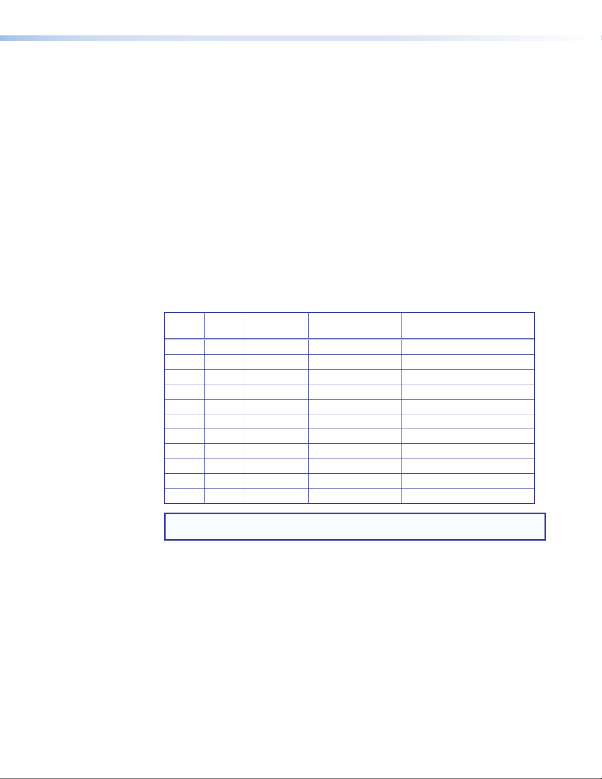
HyperLane Bus for Source Transfer
The HyperLane bus carries video source data between the input and output cards.
It allows the passage of up to 400 Gbps of video information, which translates to a
maximum of 96 native 1080p inputs at 60 Hz, or 24 4K sources at 60 Hz, all at 30 bits
per pixel.
The HyperLane bus delivers data in real time. This means that it is able to display a
source at its full temporal resolution, maintaining the same scan rate as the original
source without dropping any fields or frames. The HyperLane bus remains operational
if an operating system crash occurs, allowing crucial source content to be maintained
on the target display. The following table gives a breakdown of common resolutions and
the number of sources at that native resolution that can be passed down a 400 Gbps
HyperLane bus:
Width Height Frame Rate Bandwidth (Gbps) Number of Native Sources
1024 768 60 1.42 254
1280 720 60 1.66 217
1920 1080 60 3.73 96
1920 1200 60 4.15 86
1600 1200 60 3.46 104
2560 1600 60 7.37 48
3840 2160 30 7.46 48
4096 2160 30 7.96 45
3840 2160 60 14.93 24
4096 2160 60 15.93 22
4096 2400 60 17.69 20
NOTE: Bandwidth values do not include overhead data required for bus management.
Raw video throughput is slightly lower.
Quantum Ultra Videowall Processing System • Introduction 5
Page 14
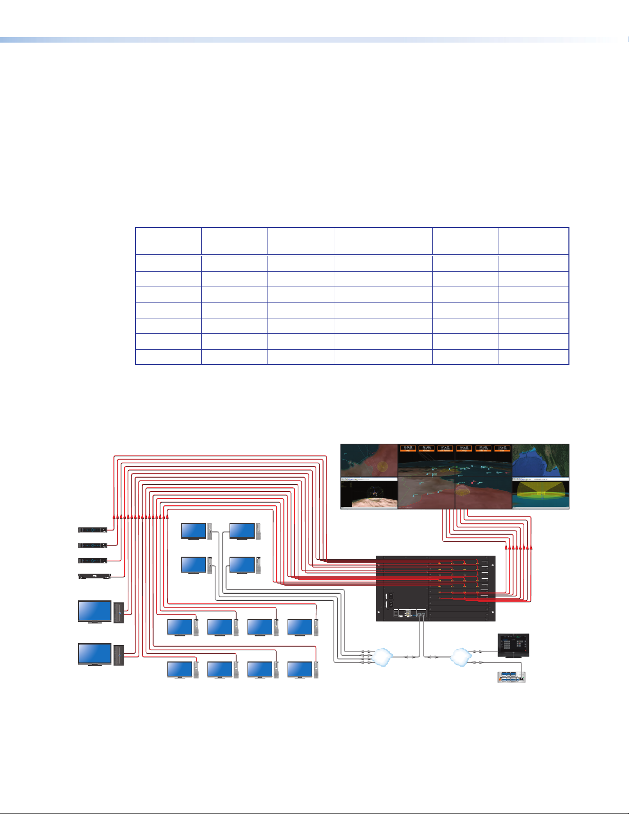
Virtual Network Computing (VNC)
ocessor
The Quantum Ultra can decode multiple VNC streams from servers loaded on remote
desktops. The VNC streams can originate on the same network used for control or on
a separate network and accessed using the second LAN port available on the Quantum
Ultra.
Desktop resolutions up to 3840x2160 are supported, but the refresh speed of the
desktop content depends on the amount of content moving or changing on the remote
desktop. The size of the VNC window on the Quantum Ultra output and the number of
VNC sources simultaneously displayed also influences the refresh rate of the content.
Below are expected frame rates of a 1920x1080 desktop at various sizes, quantity, and
amount of content in motion:
VNC
Desktop
1920x1080 3840x2160 1 full screen 5 fps 360 Mbps
Application Diagrams
The following application diagrams show examples of how the Quantum Ultra can be
connected.
HDMI HDMI
PUSH PUSH
POWERGUIDE MENU RES 480480p720p1080i1080p
DIRECTVHD
SELECT
DIRECTV
Satellite Receiver
PUSH PUSH
POWERGUIDE MENU RES 480480p720p1080i1080p
SELECT
DIRECTV
Satellite Receiver
PUSH PUSH
POWERGUIDE MENU RES 480480p720p1080i1080p
SELECT
DIRECTV
Satellite Receiver
Media Player
4K/60 Map Server
4K/60 Map Server
DIRECTVHD
DIRECTVHD
1
Remote
Workstation PC
with VNC
Remote
Workstation PC
with VNC
Workstation PC
Workstation PC
WiFi
1234
WiFi
1234
Window
Size
Number of
Windows
Amount of Motion Average
Frame Rate
Network
Usage
3840x2160 1 1/9th desktop 20 fps 190 Mbps
1920x1080 1 full screen 5 fps 360 Mbps
1920x1080 1 1/9th desktop 30 fps 400 Mbps
1920x1080 16 full screen 0.5 fps 600 Mbps
1920x1080 16 1/9th desktop 2 fps 550 Mbps
960x540 64 1/9th desktop 1 fps 980 Mbps
WiFi
1234
WiFi
1234
Workstation PC
Workstation PC
Remote
Workstation PC
with VNC
Remote
Workstation PC
with VNC
WiFi
1234
Workstation PC
WiFi
1234
Workstation PC
WiFi
1234
Extron
Quantum Ultra
Ultra-high Bandwidth
WiFi
1234
WiFi
1234
WiFi
1234
4K Videowall Processor
QUANTUM ULTRA 610
100-240V ~ --A MAX 50-60 Hz100-240V ~ --A MAX 50-60 Hz
SYSTEMREMOTE
POWER LAN
DISCONNECT POWER
CORD BEFORE
SERVICING
RS-232
CONFIG
TxRxG
INPUTS
1234
SLOT 1
INPUTS
1234
SLOT 2
INPUTS
1234
SLOT 3
INPUTS
1234
SLOT 4
INPUTS
1234
OUTPUTS
1234
OUTPUTS
1234
SLOT 8 SLOT 7 SLOT 6 SLOT 5
SLOT 9SLOT 10
AB
Workstation PC
Ethernet
Media
WiFi
1234
WiFi
1234
Ethernet
VLAN
EthernetEthernet
Control
Workstation PC
QUANTUM IN4HDMI
QUANTUM IN4HDMI
QUANTUM IN4HDMI
QUANTUM IN4HDMI
QUANTUM IN4HDMI
QUANTUM OUT4HDMI
QUANTUM OUT4HDMI
LAN
1080p HDMI 10 80p HDMI
Extron
TLP Pro 1022T
10" Tabletop
Ethernet
Ethernet
POWER
12V
--A MAX
TouchLink Pro
Touchpanel
COM 1
COM 2
DIGITAL I/O
IPCP PRO 250
Extron
G
TxRx RTSCTS
G
TxRx
1 2 3 4 G
eBUS
RELAYS
IR/S
VOL
1 2 C
VCG
+V+S-SG
IPCP Pro 250
S G
PWR OUT = 6W
LAN
IP Link Control Pr
Figure 1. Connection Diagram for a Quantum Ultra
Quantum Ultra Videowall Processing System • Introduction 6
Page 15

Extron
4K
4K
r
4K PC
4K
4K
4K
Quantum Ultra
Ultra-high Bandwidth
4K Videowall Processor
QUANTUM ULTRA 610
100-240V ~ --A MAX 50-60 Hz100-240V ~ --A MAX 50-60 Hz
SYSTEMREMOTE
POWER LAN
DISCONNECT POWER
CORD BEFORE
SERVICING
AB
RS-232
CONFIG
TxRx G
INPUTS
1234
SLOT 1
INPUTS
1234
SLOT 2
INPUTS
1234
SLOT 3
OUTPUTS
1234
SLOT 4
OUTPUTS
1234
OUTPUTS
1234
SLOT 8 SLOT 7 SLOT 6 SLOT 5
SLOT 9SLOT 10
HDMI HDMI
QUANTUM IN4HDMI
QUANTUM IN4HDMI
QUANTUM IN4HDMI
QUANTUM OUT4HDMI
QUANTUM OUT4HDMI
HDMI HDMI
Extron
TLP Pro 1022T
10" Tabletop
TouchLink Pro
Touchpanel
COM 1
COM 2
DIGITAL I/O
IPCP PRO 250
G
Tx Rx RTSCTS
G
Tx Rx
1 2 3 4 G
POWER
eBUS
RELAYS
IR/S
VOL
12V
1 2 C
VCG
--A MAX
+V+S-SG
S G
PWR OUT = 6W
Extron
IPCP Pro 250
IP Link Control Processo
LAN
Media Player
Media Player
Media Player
Media Player
1
1
1
1
WiFi
1234
Ethernet Ethernet
Control
LAN
Ethernet
Ethernet
PC
WiFi
1234
Figure 2. Connection Diagram for a Quantum Ultra
Quantum Ultra Videowall Processing System • Introduction 7
Page 16

Installation
This section provides the steps to install the Quantum Ultra processor. It also describes
the rear panel components and provides instructions for cabling. The following topics are
included:
• Installation Steps
• Rear Panel Features
• Input and Output Cards
• Connecting to a Network
Installation Steps
The Quantum Ultra processor can be mounted in a 19-inch equipment rack or placed
on a table or other furniture. To install and set up the Quantum Ultra processor for
a videowall, follow the steps below (see Application Diagrams on page 6 for
connection examples).
1. Disconnect power from the Quantum and turn off all other equipment in the system.
2. If desired, mount the processor to a rack (see Mounting on page 74).
3. Connect HDMI sources to the connectors on the installed input cards and HDMI
displays to connectors on the installed output cards. Secure each connector with a
provided LockIt bracket (see HDMI LockIt Cable Lacing Brackets on page 12).
NOTE: With adapters, DVI is available on the HDMI ports.
4. Connect a control device or computer for remote control to:
a. The rear panel RJ-45 LAN A or LAN B jack to enable configuration and control
of the Quantum via SIS commands or the VCS software (see Videowall
Configuration Software (VCS) Program on page 54 and the VCS Help File).
b. (Optional) The rear panel 3-pole captive screw RS-232 connector to enable serial
control via SIS commands (see SIS Commands on page 42).
5. Connect AC power to the IEC connectors of the Quantum Ultra primary and
redundant (optional) supplies.
NOTE: Temperature controlled fans run at 100% as a failsafe if only one power
supply is operational.
6. Power on the Quantum Ultra and all connected devices.
7. Download and install the VCS software on your computer (see Videowall
Configuration Software (VCS) Program on page 54).
Quantum Ultra Videowall Processing System • Installation 8
Page 17

8. The default IP address of the Quantum Ultra is:
• LAN A: 192.168.254.254.
• LAN B: 192.168.1.254
NOTE: A gateway IP address is required on the PC running VCS for the
Quantum Ultra to be detected. The gateway IP address does not need to be
valid or in the same subnet for the detection to work..
Set a new IP address for the Quantum using any of the following:
• VCS software — The Videowall Configuration Software for the Quantum Ultra
can be downloaded from the Extron website. Run this program on a computer
that is connected to the same network as the Quantum to assign an IP address
to the processor (see the VCS Help File for instructions).
• Internal operating system — The Quantum Ultra processor is a host device
with an embedded Windows operating system. To interact with the operating
system to change settings, you can attach peripheral USB devices, such as a
keyboard, mouse, and flash drive, to the System USB ports 1, 2, and 3 on the
rear panel. An HDMI monitor can be attached to the HDMI Out port to the left of
the System ports to let you view the settings.
• SIS commands — Using a host communication software program such as the
Extron DataViewer on your computer, enter the appropriate SIS command to set
an IP address or enable DHCP (see IP Setup on page 51).
9. Configure sources, displays, and presets for your videowall system using VCS (see
the VCS Help File).
Quantum Ultra Videowall Processing System • Installation 9
Page 18

Rear Panel Features
HH
GGFF
EE
DD
CC
AA
BB
QUANTUM ULTRA 610
100-240V ~ --A MAX 50-60 Hz100-240V ~ --A MAX 50-60 Hz
DISCONNECT POWER
CORD BEFORE
SERVICING
INPUTS
SLOT 1
INPUTS
SLOT 2
INPUTS
SLOT 3
INPUTS
SLOT 4
INPUTS
SLOT 5
OUTPUTS
SLOT 6
OUTPUTS
SLOT 7
OUTPUTS
SLOT 8
SYSTEM REMOTE
POWER LAN
AB
RS-232
CONFIG
Tx Rx G
Primary AC power connector
A
Redundant power connector
B
Power switch
C
HDMI Out system output connector
D
USB system connectors
E
SLOT 9SLOT 10
1234
1234
1234
1234
1234
1234
1234
1234
USB Config control connector
F
QUANTUM IN4HDMI
QUANTUM IN4HDMI
QUANTUM IN4HDMI
QUANTUM IN4HDMI
QUANTUM IN4HDMI
QUANTUM OUT4HDMI
QUANTUM OUT4HDMI
QUANTUM OUT4HDMI
(for future use)
RS-232 control connector
G
LAN connectors A and B
H
Input and output card slots
I
II
Figure 3. Quantum Ultra Rear Panel
Primary AC power connector — Connect AC power to this IEC connector for the
A
primary power supply.
Redundant power connector — (Optional) Connect a second AC power source to
B
this IEC connector for the secondary power supply to provide uninterrupted operation
in the event of failure of the primary supply.
NOTE: Temperature controlled fans run at 100% as a failsafe if only one power
supply is operational.
Power switch — Press the bottom of this rocker switch to power the unit (both
C
power supplies) off and on.
• If the unit is off, momentarily pressing this switch powers it on.
• If the unit is on, pressing and holding this switch for approximately 5 seconds
powers it down.
NOTE: If you are logged into the Quantum device, a momentary press of this
switch also powers it off.
HDMI Out system output connector — (Optional) Connect an HDMI monitor
D
to this female HDMI connector to view activity and interactions with the embedded
operating system.
Quantum Ultra Videowall Processing System • Installation 10
Page 19

USB system connectors — (Optional) Connect HID devices (such as a keyboard
E
or mouse) or a flash drive to one or more of these three USB A connectors to interact
with the embedded operating system.
USB Config control connector — Reserved for future use.
F
RS-232 control connector — Connect a control system or computer to this
G
3-pole 3.5 mm captive screw connector to enable control of the Quantum via SIS
commands. RS-232 protocol for this port is 9600 baud, 1 stop bit, no parity, 8 data
bits, and no flow control.
LAN connectors A and B — Connect one or both of these RJ-45 Ethernet
H
connectors to a network to access any of the following:
• A computer with the VCS software installed, to set up the videowall
• A control device such as an Extron IP Link Pro or IPCP for AV control of the
Quantum Ultra
• VNC servers to stream desktops to the Quantum Ultra
• Process SIS commands
Input and output card slots — Each of these 10 slots supports either an input
I
or an output card, depending on the configuration (see “Input and Output Cards” for
more information).
NOTE: You can also connect DVI display devices to the HDMI output connectors
using a DVI-to-HDMI cable or adapter.
Input and Output Cards
The Quantum Ultra 610 chassis contains 10 card slots for input and output cards. Each
card has four female HDMI input connectors or four female HDMI output connectors, to
which you can connect up to four HDMI sources or HDMI displays, up to the maximum
capacity of 40 HDMI inputs and outputs in nearly any combination. Multiple Quantum
Ultra chassis can be added to the same project to create very large display arrays.
Each input and output card can process up to four 2048x1200 signals at 60 Hz. On each
input and output card, connectors 2 and 4 can be configured to support up to 300 MHz.
This supports two 2560x1600 signals at 60 Hz or two 4096x2160 signals at 30 hz.
NOTE: If connector 2 is configured to support 300 MHz signals, connector 1 is
disabled and if connector 4 is configured to support 300 MHz signals, connector 3
is disabled.
You can remove, replace, and rearrange the cards in the chassis if desired (see
Replacing Input and Output Cards on page 61 for the procedure). To order
additional cards, contact your Extron representative.
The number of input and output cards installed determines how many video inputs and
display outputs are available.
NOTES:
• Input capacity is based on an input-output card configuration with one slot
occupied by an output card.
• Output capacity is based on an input-output card configuration with one slot
occupied by an input card.
Quantum Ultra Videowall Processing System • Installation 11
Page 20

The recommended cable type for the input and output connections is single link (dual
HDMI OU
T
Top Mounted
link signals are not supported), high-speed, HDMI video cable with a maximum length of
25 feet (7.6 meters). To connect DVI sources or displays to a card, use a DVI-to-HDMI
adapter.
Card Locations
When the Quantum Ultra is assembled at the factory, all the input cards are installed in
slots above the output cards in the chassis. If installing cards yourself, do not intersperse
input cards with output cards.
Each card slot can contain either an input or an output card, depending on the
configuration that was ordered (at least one input and one output card must be installed
in the chassis). However, because all the input cards must be installed together above
the output cards in the chassis, slot 1 cannot contain an output card and slot 10 cannot
contain an input card.
NOTE: Do not leave empty slots between cards (input or output) in the chassis. This
prevents the unit from functioning. Card slots that remain empty must be at the
bottom of the card slots section.
HDMI LockIt Cable Lacing Brackets
Four Extron LockIt cable lacing brackets are provided with each
TPU
HDMI card for the Quantum Ultra (additional ones can be
ordered). These brackets enable you to secure HDMI input and
3
output device cables to the HDMI connectors on the cards to
prevent intermittent or complete signal loss due to a loose cable
connection. Above each connector is a mounting screw, which
you can use to attach the lacing bracket to the Quantum Ultra
input and output cards (see the provided LockIt HDMI Lacing
Bracket Installation Guide card for more information on attaching
the bracket).
Inputs
The HDMI input cards have four female HDMI type A connectors and are
HDCP-compliant when used with HDMI output cards and HDCP-compliant displays. The
input cards provide down-scaling of sources as required.
NOTE: The HDMI connectors also support DVI signals with appropriate HDMI to DVI
cables or adapters.
• Inputs 1 and 3 — These two inputs accept resolutions with pixel clocks of up to
165 MHz, providing support for resolutions of 2048x1200 and 1920x1200 at 60 Hz.
• Inputs 2 and 4 — These two inputs accept resolutions with pixel clocks of up to
300 MHz, providing support for resolutions of 4K at 30 Hz and 2560x1600 at 60 Hz.
Digital video sources such as computers, cameras, Blu-ray™ or DVD players, and
video servers can be connected to the Quantum Ultra processor through one or more
of the input cards. These cards provide down-scaling of sources as well as full source
auto-detection.
Quantum Ultra Videowall Processing System • Installation 12
Page 21

HDCP authorization
HDCP authorization allows the unit to appear HDCP compliant or non-compliant to the
connected source. This is useful if the source automatically encrypts all content when
connected to an HDCP compliant device, if the displays in the system are not HDCP
compliant, or if the source is being shared to capture devices that do not support HDCP.
In a video system that should not transmit HDCP encrypted data, such as broadcast or
streaming environments, HDCP authorization should be disabled at the input to ensure
that the source content remains unencrypted when possible.
With HDCP authorization disabled, protected material is not passed. Each input can be
set to enable or disable the support of HDCP signals. If HDCP authorization is disabled,
the input does not negotiate with the source device and forces the source to transmit only
unencrypted video.
Source down-scaling
Each input card has an on-board scaler that can down-scale the video sources in size
down to 1/32 of the original size (horizontally, vertically, or both). Production of up to 16
instances of an input is supported, up to the total bandwidth of 18 Gbps (4K @ 60 Hz).
Width Height Frame Rate Bandwidth (Gbps)
480 270 60 0.233 16
640 360 60 0.415 16
960 540 60 0.933 16
1280 720 60 1.659 10
1920 1080 60 3.732 4
2560 1600 60 7.373 2
4096 2160 30 7.963 2
4096 2400 30 8.847 2
Should more instances be required for a preset layout, the scaler produces the required
image sizes but reduces the frame rate as needed.
Number of Unique
Instances at 60 Hz
Quantum Ultra Videowall Processing System • Installation 13
Page 22

Downscaling example
For simplicity, the example in the diagram below assumes that each screen in the target
display has the same resolution as the source.
Card Outputs
Video at Unity
Input
Card
HyperLane
Bus
Output
Card
Source Is Not Scaled
(Unity / Native Resolution / 1:1)
Card Outputs Video
Scaled Down
Input
Card
HyperLane
Bus
Output
Card
Source Is Scaled Down
Figure 4. Example of a Source Displayed Full-Sized and Down-scaled
Up-scaling (magnification) is achieved by a scaler on the output card (see Source
up-scaling on page 23).
Quantum Ultra Videowall Processing System • Installation 14
Page 23

Maximum instances of a source per input card
Processed
One unique
Pr
at 30 Hz
Processed
at 60 Hz
Four unique
Pr
at 30 Hz
The following diagrams give examples the maximum number of instances of a single
source that can be provided by one input card, at different resolutions and refresh rates.
Example 1: Four 1080p inputs at 60 Hz applied to one input card
at 60 Hz
ocessed
Processed
at 15 Hz
minication
size per source
Two unique
minication
sizes per source
Four unique
minication
sizes per source
Figure 5. Example of Four Inputs at 1080p, 60 Hz, on One Input Card
ocessed
Example 2: One 1080p input at 60 Hz applied to one input card
Figure 6. Example of One Input at 1080p, 60 Hz, on One Input Card
Quantum Ultra Videowall Processing System • Installation 15
minication sizes
for one source
Eight unique
minication sizes
for one source
Page 24

Example 3: Two 4K inputs at 30 Hz applied to one input card
At 15 Hz
At 30 Hz
One unique
ce
A
A
grouped source
minication
size per source
Two unique
minication
sizes per sour
Figure 7. Example of Two Inputs at 4K, 30 Hz, on One Input Card
Example 4: One 4K input at 30 Hz applied to one input card
t 30 Hz
t 15 Hz
At 60 Hz
At 30 Hz
At 15 Hz
Two unique
minication sizes
for one source
Four unique
minication sizes
for one source
Figure 8. Example of One 4K Input at 4K, 30 Hz, on One Input Card
Example 5: One 4K input at 60 Hz, column or quad format, applied to one
input card
One unique
minication
size for one 4K
grouped source
Two unique
minication
sizes for one 4K
grouped source
Four unique
minication
sizes for one 4K
Figure 9. Example of One 4K Input, 60 Hz, Column or Quad Format, on One
Input Card
Quantum Ultra Videowall Processing System • Installation 16
Page 25

Input rotation
ces can be shown at 15 Hz.
Sources that have their content pre-rotated can be rotated within the Quantum Ultra to
be displayed on standard, landscape formatted displays. This type of content traditionally
would originate from desktops that have portrait formatted local displays, or custom
graphics media that has portrait content rotated to fit into a standard resolution.
Figure 10. Input Rotation
The Quantum Ultra input card can support rotation of two 1920x1080 sources at 60 Hz or
one 3840x2160 source at 30 Hz. Additional sources can be rotated, but the processing
frame rate will be reduced in half to remain within the available bandwidth of the card.
Refer to the following examples.
Maximum instances of a rotated source per input card
Example 1: Four rotated 1080p inputs at 60 Hz applied to one input card
At 60 Hz
At 30 Hz
At 15 Hz
Two rotated 1080p sources
can be shown at 60 Hz.
Four rotated 1080p sources
can be shown at 30 Hz.
Two unique minications
for the four rotated 1080p
sour
Figure 11. Example of Four Rotated 1080p Inputs, 60 Hz, on One Input Card
Quantum Ultra Videowall Processing System • Installation 17
Page 26

Example 2: One rotated 1080p input at 60 Hz applied to one input card
Two unique minication
At 60 Hz
minication
ces
At 30 Hz
One unique minication
sizes for one source
At 30 Hz
Four unique
sizes for one source
Figure 12. Example of One Rotated 1080p Input, 60 Hz, on One Input Card
Example 3: Two rotated 4K inputs at 30 Hz applied to one input card
At 30 Hz
One rotated 4K source
can be shown at 30 Hz.
At 15 Hz
Two rotated 4K sour
can be shown at 15 Hz.
Figure 13. Example of Two Rotated 4K Inputs, 60 Hz, on One Input Card
Example 4: One rotated 4K input at 30 Hz applied to one input card
size for one source
At 15 Hz
Two unique minication
sizes for one source
Figure 14. Example of One Rotated 4K Input, 30 Hz, on One Input Card
Quantum Ultra Videowall Processing System • Installation 18
Page 27

Outputs
SLOT
Disabled 300 MHz 165 MHz 165 MHz
EDID management
The Quantum Ultra EDID Minder manages the EDID for all the inputs. By default, input
EDID is set to 1080p @ 60 Hz. In addition, EDID can be manually assigned to the sources
via VCS. By maintaining continuous EDID communication with all sources, EDID Minder
ensures that all sources power up properly and maintain their video outputs, whether or
not they are actively displayed on Quantum Ultra outputs.
Each input on the HDMI input cards has the option to set the EDID to be provided to the
connected source device. The preferred resolution found in custom EDID files is parsed
and the resolution and refresh rate are displayed in VCS.
NOTE: EDID for resolutions with pixel clocks above 165 MHz are available only if “up
to 300 MHz” pixel clock support has been enabled on inputs 2 and 4 (see the VCS
program help file for information on setting the resolution support).
You can set the EDID for each of the inputs in your Quantum Ultra chassis using VCS.
The software lets you view the current EDID that has been set for each input. If no project
file has been saved on the Quantum Ultra, the default EDID setting of 1080p @ 60 Hz
is applied (see the VCS help file, provided with the software, for details on selecting and
monitoring EDID).
The Quantum Ultra HDMI output cards provide the final output to a display device. They
integrate all inputs to be displayed in a layout that you define using the control software
(see the VCS Help File for information on using the program to set up displays). They also
provide up-scaling of sources.
The HDMI output cards are HDCP-compliant when used with HDMI input cards and
HDCP-compliant displays.
• Outputs 1 and 3 — These two outputs generate resolutions with pixel clocks up
to 165 MHz, which provides support for resolutions 2048x1200 and 1920x1200 at
60 Hz.
• Outputs 2 and 4 — These two outputs generate resolutions with pixel clocks up to
300 MHz, which provides support for 4K at 30 Hz and 2560x1600 at 60 Hz.
A single channel greater than 165 MHz and two channels that are less than 165 MHz is a
possible configuration. In the example in figure 15, output 2 is configured to support up to
4K at 30 Hz, and outputs 3 and 4 are configured to support up to 1920x1200 at 60 Hz.
OUTPUTS
8
1
Figure 15. Output Channel Configuration Example
Quantum Ultra Videowall Processing System • Installation 19
2
3
4
QUANTUM OUT4HDMI
Page 28

Output resolutions
The following table shows all the output resolutions and refresh rates supported on
Quantum Ultra and which connectors on the output cards support each resolution.
All — Indicates resolutions and rates supported on all connectors on the output cards.
2, 4 — Indicates resolutions and rates supported only on connectors 2 and 4.
Resolution 23.98 Hz 24 Hz 25 Hz 29.97 Hz 30 Hz 50 Hz 59.94 Hz 60 Hz
1024x768 All
1280x768 All
1280x800 All
1280x1024 All
1360x768 All
1366x768 All
1440x900 All
1400x1050 All
1680x1050 All
1600x1200 All
1920x1200 All
720p All All All All All All
1080p*** All All All All All All All All***
2048x1080 All All All All All All All All
2048x1200 All
2048x1536 2, 4
2560x1080 2, 4
2560x1440 2, 4
2560x1600 2, 4
3840x2160 2, 4 2, 4 2, 4 2, 4 2, 4
3840x2400 2, 4
4096x2160 2, 4 2, 4 2, 4 2, 4 2, 4
3840x2160 C* All All All All All 2, 4 2, 4 2, 4
3840x2400 C* All 2, 4
4096x2160 C* All All All All All 2, 4 2, 4 2, 4
3840x2160 Q** All All All All All All All All
3840x2400 Q** All
4096x2160 Q** All All All All All All All All
4096x2400 Q** All
Custom rate 1-10
* C refers to a column-formatted 4K/UHD signal comprised of two output channels to address
a full 4K raster (for example, two channels of 1920x2160 = full 3840x2160 raster).
**Q refers to a quad-formatted 4K/UHD signal comprised of four output channels to address
the full 4K raster (for example, four channels of 1920x1080 = full 3840x2160 raster).
***Default resolution and refresh rate.
Quantum Ultra Videowall Processing System • Installation 20
Page 29

Custom output resolutions
Using the VCS program, you can add custom output resolutions based on EDID that have
either been captured from the connected sink device on output 1 or uploaded (see the
VCS Help File for information on managing EDID).
NOTES:
• If the EDID pixel clock is greater than 165 MHz, you are not able to assign the
resolution to output connectors 1 and 3 (see the VCS Help File for instructions on
managing EDID).
• If the custom resolution does not work, the pixel clock may need to be
adjusted in order to be supported by the HyperLane bus. Contact an Extron
representative for assistance.
Output grouping and canvases
The VCS program provides screen workspaces called canvases (or output groups) on
which to design the videowall.
Figure 16. Canvas Example
A canvas contains a grid diagram in which each cell shows the following information
about a display on the videowall:
11
2
2
3
3
4
4
5
5
Figure 17. Canvas Cell Contents Example
• Location coordinates of the display on the wall in pixels (see figure 17, 1)
• Display number (displays are numbered horizontally on the canvas, 2).
• Name of the Quantum processor to which the display is connected (3). Displays on
a videowall can be connected to different processors.
• Number of the output card slot on the chassis, followed by the output connector
number to which the display is connected (4).
• Output resolution (5)
Quantum Ultra Videowall Processing System • Installation 21
Page 30

In the canvas example in figures 16 and 17 on the previous page, display 1 is located
at x=00 and y=00 (upper-left corner) on the videowall, the Quantum processor is named
QU610-FFFFFF, the display is connected to the output card in slot 5, output connector 1
(5.1), and the wall output resolution is 1920x1080 (1080p).
The videowall project can contain up to 10 canvases.
The following properties can be configured for each canvas:
• Output resolution
• Output rotation
• Edge blending or mullion settings
• HDCP notification
• Digital output format
A videowall design can consist of multiple canvases. A canvas can contain connectors on
any output board on any Quantum Ultra chassis, and multiple canvases can be defined
on a single output card.
Canvas 2
1080p
Rotated 90˚
Canvas 1
1366x768
40 pixel H and V mullion
Canvas 3
1080p
Rotated 90˚
Figure 18. Videowall with Multiple Canvases
In the example in figure 18, the layout utilizes three output cards (see the diagram in
figure 19).
OUTPUTS
SLOT 5
OUTPUTS
SLOT 6
1
1
2
2
3
3
4
4
QUANTUM OUT4HDMI
QUANTUM OUT4HDMI
OUTPUTS
SLOT 7
1
2
3
4
QUANTUM OUT4HDMI
Figure 19. Two Output Cards Used in one Canvas
A maximum of 10 canvases can be defined for each Quantum chassis, with each canvas
able to support up to 128 window presets associated with it. All canvases (output groups)
must be operating at refresh rates that are factors of each other to be properly supported
by the HyperLane bus (for example 60 Hz and 30 Hz or 50 Hz and 25 Hz).
Quantum Ultra Videowall Processing System • Installation 22
Page 31

Output format
Each output group (canvas) defined in the VCS can be formatted as HDMI, DVI, or Auto.
When set to Auto (the default), the output format is applied based on the EDID of the
display (see the VCS Help File for instructions on configuring and grouping the displays).
Source up-scaling
The on-board scaler on the output card provides up-scaling of live video sources.
Independent horizontal and vertical scaling is possible up to 32 times the native
(outgoing) resolution. For example, a source of 1920 x 1080 pixels can be scaled up to
approximately 61,440 x 34,560 pixels.
Card Outputs
Video at Unity
No Scaling
Required
Input
Card
RAPT
Bus
Output
Card
Source Is Not Scaled
[Unity / Native Resolution / 1:1]
Card Outputs
Video at Unity
Input
Card
RAPT
Bus
Video Scaled
Up
Output
Card
Source Is Scaled Up
[Magnification]
Figure 20. Example of a Source Displayed Full-sized and Up-scaled
NOTE: Static image files are rendered at the appropriate size by the graphics
processor (GPU). This ensures maximum image sharpness.
Down-scaling of live video sources is performed by a scaler on the input cards (see
Source down-scaling on page 13 for further details).
Quantum Ultra Videowall Processing System • Installation 23
Page 32

Maximum windows per output card
Output Channel 1.1
Output Channel 1.1
Windows 1 through 16
Windows 17 through 32
Windows 33 through 48
Windows 49 through 64
This section discusses the maximum number of source windows that each output
card can support, at different resolutions and refresh rates. A total of 64 windows are
supported per output card.
Example 1: All source windows on one output channel
In this example, 64 windows have been assigned to output channel (connector) 1.1.
No additional windows are available for output channels 1.2, 1.3, and 1.4. (Additional
windows can be assigned to other cards.)
1 8
64
Figure 21. Example of All Available Windows Assigned to One Output Channel
Example 2: All Source Windows distributed evenly among all four output
channels
1 17
16 32
Output Channel 1.2
Figure 22. Example of All Available Windows Distributed Evenly Among the Four
Output Channels.
33 49
48 64
Output Channel 1.3
Output Channel 1.4
Quantum Ultra Videowall Processing System • Installation 24
Page 33

Maximum output signals for each output card
Example 1: Four 1080p outputs at 60 Hz
Example 2:
Example 3:
Example 4:
Example 5:
The following examples show the number of output signals that are supported on each
output card, depending on resolution, refresh rate, and format (standard, column, or
quad).
10.1
Two 4K outputs at 30 Hz (channels 1 and 3 disabled)
10.2
Two 4K column outputs at 30 Hz
10.1 10.2
One 4K column output at 60 Hz (channels 1 and 3 disabled)
10.2 10.4
One 4K quad output at 60 Hz
10.1
10.2
10.2 10.3 10.4
10.4
10.3 10.4
10.3 10.4
Figure 23. Maximum Number of Output Signals Per Output Card at Different
Resolutions and Refresh Rates
Quantum Ultra Videowall Processing System • Installation 25
Page 34

Output Rotation
Example 1: Two rotated 1080p outputs at 60 Hz (connectors 1 and 3 disabled)
If the displays in the videowall are installed in a portrait orientation, the output signal from
the Quantum Ultra can be rotated to support the rotated displays. In contrast to input
rotation which will rotate the source content within a window, output rotation affects
the entire output signal which includes all sources, window text, images, and HDCP
messaging.
Figure 24. Output Rotation
The Quantum Ultra output card can support rotation of two 1920x1080 outputs at 60
Hz or one 3840x2160 output at 30 Hz. When rotation is enabled, only outputs 2 and
4 are addressable if the resolution pixel clock is less than 165MHz and only output 4
is addressable if the output resolution is greater than 165Mhz. Refer to the following
examples.
Maximum rotated output signals for each output card
The following examples show the number of rotated output signals that are supported on
each output card at different resolutions and refresh rates.
10.2
Example 2: One rotated 4K output at 30 Hz (connectors 1, 2, and 3 disabled)
10.4
Figure 25. Maximum Number of Rotated Output Signals Per Output Card at
Different Resolutions and Refresh Rates
NOTE: Column and quad outputs cannot be rotated.
10.4
Quantum Ultra Videowall Processing System • Installation 26
Page 35

Adjusting for Mullion Compensation and Edge Blending
Horizontal Mullion
n
When setting up the videowall, you can select test patterns via the VCS that help you
define the following adjustments:
• Mullion compensation — Mullion is the area of frame border that exists around
each display. When designing the videowall, you must take this area into account
so that, when an image is spread across two or more displays, the image flow is
not distorted. The VCS enables you to adjust the space around each display to
compensate for the mullion.
• Edge blending compensation — In certain situations it may be desirable to create
an overlap of video between adjacent displays. This overlap melds the two images
from two separate outputs into a single image and prevents a visible separation line
between the two images. Use the VCS to set or adjust the amount of horizontal and
vertical overlap of the videowall displays.
Each output canvas maintains its unique edge compensation settings with discrete values
for the horizontal and vertical edges. The settings are applicable to all edges within the
canvas.
See the VCS Help File for instructions on adjusting to compensate for mullion and edge
blending.
(50 pixels)
Figure 26. Example of Mullion Compensation Settings on a Canvas
NOTE: For information about replacing input and output cards, see Replacing Input
and Output Cards beginning on page 61.
Connecting to a Network
The Quantum Ultra provides an Ethernet network connection over UTP that is separate
from the network port dedicated for control. In secure installations, it is often preferable
for the AV control network to be isolated and separate from the standard house network
which would provide access to the rich media content that the Quantum Ultra chassis
supports. You can access VNC sessions on your network using one LAN port, and the AV
control IP connection is not required to also be on your data network.
Connect a computer that is running the Videowall Configuration Software to the Ethernet
(10/100/1000Base-T) LAN A or LAN B port on the rear panel to enable you to control the
Quantum Ultra processor and to set up videowall applications via the computer.
Vertical Mullio
(100 pixels)
NOTE: Ensure that the PC and the Quantum Ultra processor are on the same subnet.
Quantum Ultra Videowall Processing System • Installation 27
Page 36

Setup of the Quantum Ultra chassis is achieved using the Videowall Configuration
Software. The default IP address for the LAN port A is 192.168.254.254, but with SIS,
you can set the IP address without interacting directly with the embedded operating
system interface. LAN port B is not accessible via SIS but can be configured via the VCS
or the embedded operating system.
After the system is configured with the desired wall layout and window presets, the
Quantum Ultra can be controlled directly by a control system via the Ethernet or RS-232
connection.
The network port on the computer or the network hub, router, or LAN must be able to
support a 100Base-T connection. When the Quantum Ultra processor is delivered, it is set
with the following default addresses and values:
• IP address:
LAN A: 192.168.254.254
LAN B: 192.168.1.254
• Subnet mask: 255.255.255.0
• Gateway: 0.0.0.0
To change these addresses, you can use the Videowall Configuration Software (see the
VCS Help File), the Control Panel (see Starting the Control Panel on the next page) or
SIS commands (see IP Setup on page 51).
NOTE: To enable communications between the computer and the processor, the
Quantum Ultra IP address and subnet mask must be compatible as follows:
• The subnet mask must be the same for all devices.
• The IP addresses must be different, but on the same subnet.
Quantum Ultra Videowall Processing System • Installation 28
Page 37

Operation
,
HDMI Out
f
The Quantum Ultra processor is a host device with an embedded operating system. The
Quantum Ultra Control Panel is a program that resides on the Quantum Ultra operating
system and enables you to perform various setup and maintenance tasks, such as setting
the processor IP address, resetting the device, or updating the firmware.
This section discusses the functions accessed via the Control Panel:
• Starting the Control Panel
• Control Panel Buttons
• Loading Image Files
• Updating the Password
• Updating Firmware
• Modifying Network Settings
• Resetting the Device
• Service Mode
• Committing Changes to Memory
• Shutting Down
Starting the Control Panel
To access the Quantum Ultra Control Panel:
1. Connect a USB keyboard and mouse to the USB system connectors on the rear
panel (see figure 27). You can also connect a USB flash drive to a USB system
connector to load and manage picture files or upload new firmware.
Port
or Monitor
Figure 27. System Ports for Keyboard, Mouse, and Monitor
2. Connect a monitor to the HDMI Out system connector on the rear panel. A login
window appears with the user name displayed (by default, this name is admin).
SYSTEM
USB Ports for Keyboard
Mouse, or Flash Drive
Quantum Ultra Videowall Processing System • Operation 29
Page 38

3. Enter the password where indicated on the login window (by default, the password is
extron). The Quantum Ultra Control Panel main window appears on the monitor, in
front of a background image of the Quantum Ultra. From this window, you can access
all common tasks.
Figure 28. The Quantum Ultra Control Panel Main Window
4. The Control Panel main window contains eight buttons that let you access the
setup and management tasks for the Quantum Ultra (see figure 28, 6). Click one
of these buttons to proceed to the desired task (see Control Panel Buttons on the
next page).
The Control Panel window also contains the following status panels that enable you
to observe status and activity of each major component:
Hardware Status
1
Network Interface Status
2
System Status
3
Firmware Status
4
CPU Usage progress bar
5
NOTE: If the Control Panel window is closed, press <Ctrl + F2> to reopen it.
Quantum Ultra Videowall Processing System • Operation 30
Page 39

Control Panel Buttons
The following buttons give you access to set up and manage the Quantum Ultra via the
Control Panel (see figure 28 on the previous page).
NOTE: When you click a Control Panel button, a password prompt appears.
Enter the operating system password, then click OK. The login defaults are:
• Username — admin
• Password — extron
• Add Picture Files — Enables you to load image files (.bmp, .png, or .jpg) to the
Quantum Ultra D: drive (see “Loading Image Files”). These pictures are then available
to display on the videowall (see the VCS Help File to add images to the videowall
project).
• Update Password — Enables you to update the hardware password to access the
Quantum Ultra Control Panel (see Updating the Password on page 33).
• Update Firmware — Provides options to install new firmware or roll back to a
previous version (see Updating Firmware on page 34).
• Network Settings — Displays the Network Settings window, from which you
can view or modify the IP addresses of the LAN A and LAN B ports (see Modifying
Network Settings on page 38).
• Reset Device — Enables you to reset the Quantum Ultra to different levels of the
default state (see Resetting the Device on page 39).
• Service Mode — Provides access to the file system and a shortcut to the operating
system control panel, where you can update the date and time (see Service Mode
on page 40).
• Commit Changes — Applies any changes made to the C: drive or the operating
system configuration during the session (see Committing Changes to Memory on
page 41).
• Shutdown — (Optional) Performs an orderly shutdown of the Quantum Ultra system.
Loading Image Files
You can upload image files from an external USB drive to the Quantum Ultra processor to
be displayed as sources in windows and incorporated into presets. The following image
file types are supported:
• Bitmaps (.bmp)
• JPEG (Joint Photographic Experts Group) images (.jpg or .jpeg)
• Tagged image format file (.tif, .tiff)
• Portable Network Graphics (.png)
To upload image files to the Quantum Ultra hard drive:
1. Connect the external USB drive containing the images to one of the rear panel
System USB ports.
2. On the Quantum Ultra Control Panel window, click Add Picture Files.
3. On the password prompt window that opens, enter the username and password,
then click Enter.
Quantum Ultra Videowall Processing System • Operation 31
Page 40

4. In the directory window that opens, navigate to the USB flash drive containing the
pictures. In the example below, that drive is E:. Yours may be a different drive.
Figure 29. USB Flash Drive Containing Picture Files
5. On the USB drive, locate the image files to be loaded to the Quantum Ultra and drag
or copy them to the Pictures folder on the Quantum Ultra D: Data drive.
Figure 30. Copying Two Picture Files to the Quantum Ultra Data Drive
The files can now be accessed via the VCS for use in configuration (see the VCS Help
File for information on creating presentations).
Quantum Ultra Videowall Processing System • Operation 32
Page 41

Updating the Password
To change the password to access the operating system:
1. Click the Update Password button on the Control Panel window.
2. On the Change Password window, enter in the appropriate fields:
• The current password (the default password is extron)
• The new password
• The new password again to confirm it
Figure 31. Change Password Fields
3. Click the Enter button at the bottom of the Change Password window. The following
prompt opens, informing you that you must reboot the unit for the new password to
take effect.
Figure 32. Password Reboot Prompt
4. Click OK to reboot. (If you click Cancel, the new password remains in effect only until
the system is shut down.)
Quantum Ultra Videowall Processing System • Operation 33
Page 42

Updating Firmware
If it becomes necessary to update the firmware on your Quantum Ultra, you can obtain
new firmware at www.extron.com and upload it to the unit.
Downloading a Firmware File
1. On the Extron web page, select the Download tab (see figure 33, 1).
2. On the Download screen, click either Firmware (2) in the left sidebar panel or the
Firmware icon (
) in the main panel.
3
Figure 33. Downloading Firmware
Quantum Ultra Videowall Processing System • Operation 34
Page 43

3. On the Download Center screen, click the Q link (see figure 34, 1).
SYSTEM
USB System Ports
4. Scroll to locate the Quantum Ultra firmware and click the Download link at the far
right (2).
Figure 34. Install Software Window
5. Follow the instructions on the subsequent screens to download and save the firmware
file on your computer.
Uploading a Firmware File
To upload a new firmware file to the Quantum Ultra:
1. Copy the new firmware file to a USB flash drive.
2. Plug the flash drive into one of the System USB ports on the rear panel (see figure 35).
for Flash Drives
Figure 35. USB System Ports on the Rear Panel
3. On the Control Panel window, click the Service Mode button.
4. Enter password.
5. Copy the firmware file from the USB drive to the root of the D: drive.
6. On the Control Panel window, click the Update Firmware button.
Quantum Ultra Videowall Processing System • Operation 35
Page 44

7. On the System Management window that appears next, enter your password
(extron, by default).
8. On the Firmware Options screen, click Upgrade or Roll back firmware.
Figure 36. Selecting Upgrade or Roll Back Firmware
9. On the next screen, click the Browse button and locate the new firmware file on the
USB flash drive (usually E:).
10. Double-click on the firmware file or select it and click Open. The Quantum Ultra
firmware file must have a .gpg extension.
Figure 37. Selecting the Firmware File on the USB Flash Drive
Quantum Ultra Videowall Processing System • Operation 36
Page 45

11. On the Firmware update screen, click Install (see figure 38, 1).
Figure 38. Click Install on the Firmware Update Screen
12. On the confirmation prompt that appears, click OK to proceed with the firmware
installation.
The Quantum Ultra Control Panel screen displays progress messages (see
figure 39, 1) in the upper-left corner, while a progress bar (2) at the bottom of the
screen lets you know approximately how much time remains for the installation.
Figure 39. Installation Progress Screen
When the installation is completed, Success! appears in the upper-left corner of the
screen.
Quantum Ultra Videowall Processing System • Operation 37
Page 46

13. A prompt appears, telling you to reboot the Quantum Ultra. Click OK.
Figure 40. Reboot Prompt after Firmware Update
The Quantum Ultra restarts with the new firmware.
ATTENTION:
• Wait until the opening screen appears before performing any other
operations.
• Attendez jusqu’à ce que l’écran d’accueil apparaisse avant d’effectuer une
quelconque opération.
Modifying Network Settings
To change the IP addresses of the LAN A and LAN B ports:
1. On the Control Panel window, click the Network Settings button. The Network
Settings window opens.
Figure 41. Network Settings for LAN A Port
2. If desired, enter a name of 1 to 15 characters for your Quantum Ultra. Only letters,
numbers, and the hyphen (-) can be used in this name.
NOTE: All letters in the Device Name are displayed in uppercase.
3. Select the tab for the LAN port (LAN A or LAN B) to configure.
Quantum Ultra Videowall Processing System • Operation 38
Page 47

4. Either:
• Select the Use DHCP checkbox to automatically assign all IP addresses, or
• Enter the addresses in the IP Address, Subnet Mask, Default Gateway, and
NOTE: The Media Access Code (MAC) hardware address cannot be changed.
5. If desired, select the tab for the other LAN port and repeat step 4 for it.
6. When finished, click OK.
Resetting the Device
The Reset Device button on the Control Panel main window (see figure 28 on
page 30) displays the Reset Device window, on which you can select the type of reset to
perform.
DNS Server.
Figure 42. Reset Device Window
To reset the unit:
1. Select the radio button for the type of reset desired:
• Reset Device Settings (Retain TCP/IP Settings and Image Files) —
Resets the Quantum Ultra to its factory default settings while keeping the IP
addresses and other settings that have been entered, plus any image files that
have been uploaded. This is the default.
• Reset Device Settings and Delete All Files (Retain TCP/IP Settings)
— Resets the unit to factory defaults and keeps IP address information. All
uploaded image files are deleted and the default image files are restored.
• Reset All Settings and Delete All Files — Resets the unit to factory
defaults. All user-uploaded image files are deleted, IP settings are reset to default,
and the default image files are restored.
2. Click the Reset button located below the radio buttons. The unit resets and reboots.
Quantum Ultra Videowall Processing System • Operation 39
Page 48

Service Mode
In service mode, you can access the Quantum Ultra C: and D: drives as well as the
operating system Control Panel. To enter service mode:
1. On the Quantum Ultra Control Panel main window, click Service Mode.
2. On the Admin Authentication screen, enter your system password where indicated
and click Enter. The File Explorer window opens.
Figure 43. File Explorer Window in Service Mode
3. On the Computer window, you can open and manage files on the system (see
figure 43, 1).
You can also display the operating system Control Panel by clicking Control Panel
(2) in the Favorites (left) panel. From here, you can adjust the system settings.
Quantum Ultra Videowall Processing System • Operation 40
Page 49

Committing Changes to Memory
The Quantum Ultra Control Panel enables you to commit (save) to memory all changes
made to the C: drive and operating system configuration during the session. These saved
settings remain in effect the next time the Quantum Ultra is powered on.
NOTE: You must have administrator clearance in order to commit changes.
1. On the Quantum Ultra Control Panel window (see figure 28, 6, on page 30) click
Commit Changes. The following window opens:
Figure 44. Reboot Confirmation Prompt to Commit Changes
2. Click OK to reboot the unit.
3. On the Password Verification window, enter the administration password and
click Enter. The system reboots and your changes are saved.
ATTENTION:
• While the processor is rebooting, do not press any keys or attempt to power
off the system.
• Pendant la réinitialisation du processeur, n’appuyez sur aucune touche et
n’essayez pas d’éteindre le système.
Shutting Down
When the reboot is complete, the Quantum Ultra Control Panel main window is
displayed. All the settings are saved to memory and remain in effect until changed.
If required, use one of the following methods to shut down the Quantum Ultra:
• Press and hold the rear panel power switch for 5 seconds (see figure 3, C, on
page 10).
• If logged into the Quantum Ultra operating system, you can momentarily press the
rear panel power switch.
• When a keyboard, mouse, and monitor are attached, the Quantum Ultra can be shut
down via the Control Panel. To perform an optional orderly shutdown:
1. click Shut down. A confirmation prompt appears:
Figure 45. Shutdown Confirmation Prompt
2. Click OK. The Quantum Ultra shuts down.
Quantum Ultra Videowall Processing System • Operation 41
Page 50

Remote Configuration and Control
This section describes the methods by which the Quantum Ultra can be configured and
controlled remotely: the Extron Simple Instruction Set (SIS) commands and the Videowall
Configuration Software (VCS). It describes the available SIS commands and how to
enter them, as well as providing instructions for obtaining and accessing the VCS. Topics
include:
• SIS Commands
• Command and Response Table for SIS Commands
• Videowall Configuration Software (VCS) Program
SIS Commands
You can use SIS commands to configure and control the Quantum Ultra via a host
computer or other device (such as a control system) attached to the rear panel RS-232
connector or the rear panel LAN port. Enter commands using a host communication
application such as the Extron DataViewer, available at www.extron.com (see the
DataViewer Help file to use this program). The RS-232 port uses a protocol of 9600 baud,
8 data bits, 1 stop bit, no parity, and no flow control.
SIS commands consist of one or more characters per field. No special characters are
required to begin or end a command sequence. When the Quantum determines that a
command is valid, it executes the command and sends a response to the host device.
All responses from the Quantum to the host end with a carriage return and a line feed
(CR/LF = ]), indicating the end of the response character string (one or more characters).
Copyright Information
The Quantum sends the following copyright message at initial power-up:
] (c) Copyright 20nn, Extron Electronics, Quantum Ultra 610, Vn.nn,
60-1571-01]
Www, DD Mmm 20nn hh:mm:ss]
(Where Vn.nn is the firmware version, 60-1571-01 is the part number, Www is the day of
the week, DD is the day of the month, Mmm is the month name, and 20nn is the year.)
Quantum Ultra Videowall Processing System • Remote Configuration and Control 42
Page 51

Quantum Ultra-initiated Messages
ASCII to HEX Conversion Ta ble
Space
.
When a local event such as a software selection or adjustment takes place, the
Quantum Ultra responds by sending a message to the host. No response is required from
the host. An example of a Quantum Ultra-initiated message is:
1 Rpr X#*
X2% ]
(Window preset
Error Responses
When the Quantum Ultra receives a valid command, it executes the command and sends
a response to the host device. If the unit is unable to execute the command, it returns an
error response followed by a carriage return and line feed to the host.
E01 — Invalid input number
E10 — Invalid command
E11 — Invalid preset number
E13 — Invalid parameter
E14 — Invalid command for this configuration
E17 — Invalid command for signal type
E22 — Busy
E24 — Privilege violation
E25 — Device not present
E26 — Maximum number of connections exceeded
E28 — Bad file name or file not found
X2%
for canvas X#).
Using the Command and Response Table
The Command and Response Table for SIS Commands, beginning on page 46,
lists the commands that the Quantum Ultra processor recognizes as valid, the responses
that are returned to the host, a description of the command function or the results of
executing the command, and some examples of the command syntax in ASCII.
NOTE: Unless otherwise stated, upper- and lowercase text can be used
interchangeably in the commands.
Figure 46. ASCII to Hexadecimal Character Conversion Table
Quantum Ultra Videowall Processing System • Remote Configuration and Control 43
Page 52

Symbol Definitions
• = Space
]
= Carriage return with line feed
}
or | = Carriage return with no line feed
E
or W = Escape
24
= Superscripts indicate the error message returned if the command is entered incorrectly
or with invalid parameters (see Error Responses on the previous page).
NOTE: If the unit does not support or recognize an entered command, it may not respond to
the command in any way.
X!
= Input selection — 1 through 9999 (assigned by the VCS software)
Response is four digits with leading zeros.
1-999 = Physical video connections on all chassis in the system
1000-9999 = VNC, image, and clock sources defined in the system
X@
= Output selection — 1-9999 (assigned by VCS)
Physical video connections on all chassis in the system
Response is four digits with leading zeros.
X#
= Canvas selection — 1 through 10
Response is two digits with leading zero.
0 = All canvases (for window mute only)
X$
= Source format
0 = No signal present
1 = HDMI
5 = VNC
6 = Clock
7 = Image file (.bmp, .jpg, or .png)
X%
= Window selection — 1 through 999
0 = All windows (for window mute only)
Response is three digits with leading zeros.
X1)
= On or off (enable or disable)
0 = Off or disable
1 = On or enable
X1@
= Internal temperature in degrees Celsius
Response is two digits with a leading zero.
X1#
= Horizontal and vertical frequencies
Response format is three digits with leading zeros and one decimal place
(example: 075.3).
X1^
= Horizontal and vertical position (Limits depend on input or output resolutions.)
Response is six digits with a leading + or - and padded with zeros (example: -000175).
X1&
= Horizontal and vertical size (Limits depend on input or output resolutions.)
Response is six digits, padded with zeros (example: 000175).
X2%
= Window or style presets — 1 through 128
Response is three digits padded with zeros.
X4@
= Window mute
0 = Off (unmute) (default)
1 = On (mute window)
X7*
= Window priority position — 1 through 999
1 = Back (lowest priority)
Response is three digits padded with zeros.
X8)
= Input resolution — Horizontal and vertical dimensions. Example: 1280x720
Quantum Ultra Videowall Processing System • Remote Configuration and Control 44
Page 53

IP setup symbol definitions
X11!
= Firmware version number (listed to two decimal places)
X11@
= Name — Text string of up to 15 characters: A-Z, 0-9, and hyphen or minus sign (-).
• No blank or space characters are permitted.
• No distinction is made between upper- and lowercase.
• The first character must be an alpha character (A-Z, a-z).
• The last character cannot be a minus sign or hyphen.
X11#
= IP address (nnn.nnn.nnn.nnn)
Leading zeros in each of the four octets are optional in setting values, and are suppressed
in returned values.
X11$
= Gateway IP address (nnn.nnn.nnn.nnn)
Leading zeros in each of the four octets are optional in setting values, and are suppressed
in returned values.
X11*
= Hardware (MAC) address (00-05-A6-xx-xx-xx)
X11(
= Subnet mask (nnn.nnn.nnn.nnn)
Leading zeros in each of the four octets are optional in setting values, and are suppressed
in returned values.
X12@
= Verbose mode
0 = None (default for LAN connection)
1 = Verbose mode (default for RS-232 connection)
2 = Tagged response for queries
3 = Verbose mode and tagged response for queries
NOTES:
• In verbose response mode, the Quantum Ultra responds with unsolicited
responses for value and setting changes that may result from a signal change,
or a setting adjustment made via another interface.
For example, the Quantum Ultra can send out a notice of a change in some
setting without receiving a query via a PC or a control system. That change
could have been a result of an internal process or a selection made via the VCS
program. This is an example of a verbose (wordy) relationship between the
controller and a connected device.
• If tagged responses are enabled, all “view” commands return the command
string plus the data, the same as in responses for setting a value. For example:
Command:
Response: Wndw P X% * X# *
or
E
P X# * X% WNDW }
X7* ]
(untagged response)
X7* ]
(tagged response)
X13#
= Password
• Length is 1-128 characters.
• All human-readable characters permitted except the pipe character (|).
• The password cannot be a single space.
• Passwords are case-sensitive.
• A user password cannot be assigned if no administrative password exists. An E14 error
code is returned.
• If the admin password is cleared, the user password is cleared as well.
X14!
= Reading password. Response is four asterisks (****) if a password exists, empty if none
exists.
X14(
= Default name — Combination of model name and last three character pairs of the MAC
address (Example: QU610-00-02-3D)
X17^
= Network Interface
1 = LAN A
2 = LAN B
X17&
= Prefix (subnet mask bits). Subnet 255.255.255.0 is represented as a prefix value by /24.
The default response for the E CISG command (on IPv4) is /24.
Quantum Ultra Videowall Processing System • Remote Configuration and Control 45
Page 54

Command and Response Table for SIS Commands
ASCII Command
Command
(Host to Processor)
Input Switching and Configuration
Input Selection
Select input
View current input
X#
* X% * X! ! Grp X# • Win X% •
X#
* X% !
Picture Adjustments
Window Mute
Mute window
Unmute window
View mute status
Window Priority
Send to back
Send backward
Bring forward
Bring to front
View window priority
X#
* X% * 1B Vmt X# * X% * 1
X#
* X% * 0B Vmt X# * X% * 0
X#
* X% B
E
P X# * X% * 0 WNDW
E
P X# * X% * 1 WNDW
E
P X# * X% * 2 WNDW
E
P X# * X% * 3 WNDW
E
P X# * X% WNDW
}
Response
(Processor to Host) Additional Description
Select input X! for window X%
]
In X!
X! ]
In verbose modes 2 and 3:
Grp X% • Win X# •
]
In X!
]
]
X4@ ]
In verbose modes 2 and 3:
Vmt X% * X# *
X4@ ]
on canvas X#.
View currently selected input
X!
in window X% on canvas
X#
.
Mute window X% on canvas X#.
Unmute window X% on canvas
X#
.
View mute status
window X% on canvas X#.
X4@
}
Wndw P X# * X% * 0
]
Place window X% behind all
other windows on canvas X#.
}
Wndw P X# * X% * 1
]
Move window X% back one
layer on canvas X#.
}
Wndw P X# * X% * 2
]
Move window X% forward one
layer on canvas X#.
}
Wndw P X# * X% * 3
]
X7*
In verbose modes 2 and 3:
Wndw P X# * X% *
]
X7* ]
Place window X% in front of all
other windows on canvas X#.
View the priority (
window X% on canvas X#.
X7*
of
) of
NOTES:
X!
= Input number: 1 through 9999 (assigned by the VCS program). Response is four digits with leading zeros.
1-999
1000-9999
X#
= Canvas number: 1 through 10. Response is two digits with leading zero.
0 = All canvases (for window mute only)
X%
= Window number: 1 through 999. Response is three digits with leading zeros.
0 = All windows (for window mute only)
X4@
= Window mute: 0 = Unmute (default), 1 = Mute window.
X7*
= Window priority number: 1 through 999. Response is three digits with leading zeros.
1 = back (lowest priority)
= Physical video connections on all chassis in the system
= VNC, image, and clock sources defined in the system
Quantum Ultra Videowall Processing System • Remote Configuration and Control 46
Page 55

Command
Picture Adjustments
Horizontal Shift (Window)
Specific value
Increment value
Decrement value
View window shift
Vertical Shift (Window)
Specific value
Increment value
Decrement value
View window shift
Horizontal Size (Window)
Specific value
Increase horizontal size
Decrease horizontal size
View horizontal size
ASCII Command
(Host to Processor)
E
W X# * X% *
E
W X# * X% +HCTR
E
W X# * X% -HCTR
E
W X# * X% HCTR
E
W X# * X% *
E
W X# * X% +VCTR
E
W X# * X% -VCTR
E
W X# * X% VCTR
E
W X# * X% *
E
W X# * X% +HSIZ
E
W X# * X% -HSIZ
E
W X# * X% HSIZ
X1^
X1^
X1&
Response
(Processor to Host) Additional Description
}
HCTR
Hctr W X# * X% *
}
Hctr W X# * X% *
}
Hctr W X# * X% *
} X1^ ]
In verbose modes 2 and 3:
Hctr W X# * X% *
}
VCTR
Vctr W X# * X% *
}
Vctr W X# * X% *
}
Vctr W X# * X% *
} X1^ ]
In verbose modes 2 and 3:
Vctr W X# * X% *
}
HSIZ
Hsiz W X# * X% *
}
Hsiz W X# * X% *
}
Hsiz W X# * X% *
} X1& ]
In verbose modes 2 and 3:
Hsiz W X# * X% *
X1^ ]
X1^ ]
X1^ ]
X1^ ]
X1^ ]
X1^ ]
X1^ ]
X1^ ]
X1& ]
X1& ]
X1& ]
X1& ]
Shift window X% on canvas X#
X1^
X1^
.
.
X1^
of
X1^
of
X1&
of
horizontally to
Shift window X% on canvas X#
one pixel to the right.
Shift window X% on canvas X#
one pixel to the left.
View horizontal position
window X% on canvas X#.
Shift window X% on canvas X#
vertically to
Shift window X% on canvas X#
down by one line.
Shift window X% on canvas X#
up by one line.
View vertical position
window X% on canvas X#.
Set the horizontal size (width)
of window X% on canvas X# to
X1&
.
Widen window X% on canvas
X#
by one pixel.
Narrow window X% on canvas
X#
by one pixel.
View horizontal size
window X% on canvas X#.
NOTES:
X#
= Canvas number: 1 through 10. Response is two digits with leading zero.
0 = All canvases (for window mute only)
X%
= Window number: 1 through 999. Response is three digits with leading zeros.
0 = All windows (for window mute only)
X1^
= Horizontal and vertical position (Limits depend on input or output resolutions.)
Response is six digits with leading + or - and padded with zeros.
X1&
= Horizontal and vertical size (Limits depend on input or output resolutions.)
Response is six digits and padded with zeros.
Quantum Ultra Videowall Processing System • Remote Configuration and Control 47
Page 56

ASCII Command
Command
(Host to Processor)
Picture Adjustments (continued)
Vertical Size (Window)
Specific value
Increase vertical size
Decrease vertical size
View
E
W X# * X% *
E
W X# * X% +VSIZ
E
W X# * X% -VSIZ
E
W X# * X% VCTR
Compound Window Position and Size
Specific value
View size and position
E X#
E X#
* X% ,
* X% XWIN
Window Presets
Recall preset
Save preset
Delete preset
1 * X# *
1 * X# *
E
X2%
X2%
X 1*X#*
Response
(Processor to Host) Additional Description
X1&
VSIZ
}
}
}
Vsiz W X# * X% *
Vsiz W X# * X% *
Vsiz W X# * X% *
} X1& ]
In verbose modes 2 and 3:
Vsiz W X# * X% *
X1^
X1^
X1&
*
*
} X1^
. 1 Rpr X#*
, 1 Spr X#*
X2%
PRST
}
X1&
*
XWIN
Xwin X# * X% ,
X1^
*
In verbose modes 2 and 3:
Xwin X# * X%,
Prst X 1*X# *
X1&
*
X2% ]
X2% ]
}
X1^
*
X1^
X2% ]
X1& ]
X1& ]
X1& ]
X1& ]
X1^
*
X1& ]
X1^
*
Set the vertical size (height) of
window X% on canvas X# to
X1&
.
Increase the vertical size of
window X% on canvas X# by
one line.
Decrease the vertical size of
window X% on canvas X# by
one line.
View vertical size
window X% on canvas X#.
X1&
*
X1& ]
*
Set the horizontal and vertical
position (
and vertical size (
window X% on canvas X#.
X1^
X1&
) and horizontal
X1&
X1&
*
X1& ]
*
View the horizontal and vertical
positions and sizes of window
X%
in canvas X#.
Recall window preset
canvas X#.
Save window preset
canvas X#.
Clear window preset
X2%
and set its name to
[unassigned].
of
) for
X2%
X2%
for
for
NOTES:
X#
= Canvas number: 1 through 10. Response is two digits with leading zero.
0 = All canvases (for window mute only)
X%
= Window number: 1 through 999. Response is three digits with leading zeros.
0 = All windows (for window mute only)
X1^
= Horizontal and vertical position (Limits depend on input or output resolutions.)
Response is six digits with leading + or -, padded with zeros.
X1&
= Horizontal and vertical size (Limits depend on input or output resolutions.)
Response is six digits, padded with zeros.
X2%
= Window preset number: 1 through 128. Response is three digits padded with zeros.
Quantum Ultra Videowall Processing System • Remote Configuration and Control 48
Page 57

Command
Window Border Style
Set border style
View border style
Resets
System reset
Absolute system reset
Absolute system reset,
retain IP settings
Reboot system and save
network settings
Reboot system and
discard network settings
ASCII Command
(Host to Processor)
E
B X# * X% *
E
B X# * X% WNDW
E
ZXXX
E
ZQQQ
E
}
ZY
E
1 BOOT } Boot 1 ]
E
3 BOOT } Boot 3 ]
}
}
X2%
WNDW
} X2% ]
Response
(Processor to Host) Additional Description
}
Wndw B X# * X% *
In verbose modes 2 and 3:
Wndw B * X# * X% *
Zpx
Zpq
Zpy
]
]
]
X2% ]
X2%]
Set the window border style to
X2%
.
View the current border style
X2%
on window X% on canvas
X#
.
Reset all device settings to
factory defaults and reset any
passwords. Project files are
deleted and the unit is rebooted
to commit video outputs to
memory and clear them. IP
addresses and picture files
remain untouched.
Set all device settings plus
DHCP and the IP addresses to
factory defaults, and reset any
passwords. Project files are
deleted, picture folders cleared,
and the unit is rebooted.
Same as absolute system reset
except that IP addresses are not
reset. Project files are deleted,
picture folders cleared, all
passwords are cleared, and the
unit is rebooted.
Reboot the system and retain
the network settings.
Reboot the system and discard
the network setting changes.
NOTES:
X#
= Canvas number: 1 through 10. Response is two digits with leading zero.
0 = All canvases (for window mute only)
X%
= Window number: 1 through 999. Response is three digits with leading zeros.
0 = All windows (for window mute only)
X2%
= Window or style presets — 1 through 128. Response is three digits padded with zeros.
Quantum Ultra Videowall Processing System • Remote Configuration and Control 49
Page 58

Command
ASCII Command
(Host to Processor)
Response
(Processor to Host) Additional Description
Information Requests
General information
Query model name
Query firmware version
Query firmware build
version
Query part number
View internal temperature
Query hardware status
Example: S Sts1 1 1 1 26
X#
* X% * I Grp X#•Win X%•In X!•Typ X$•Blk
(Responses are the same in verbose modes 2 and 3.)
1I
Q
*Q
N
E
20STAT
S
<Primary PSU>, <redundant PSU>, <top fans>, <rear fans>, <temperature>
} X1@ ]
Quantum Ultra 610 ]
In verbose modes 2 and 3:
Inf01 * Quantum • Ultra • 610
n.nn
In verbose modes 2 and 3:
Ver01 * n.nn
n.nn.nnnn-bnnn
In verbose modes 2 and 3:
Bldn.nn.nnnn-nnnn
60-1571-01
In verbose modes 2 and 3:
Pno 60-1571-01
In verbose modes 2 and 3:
20Stat •
X1)•X1)•X1)•X1)•X1@]
Quantum Ultra-initiated Messages
FAILED: Power Supply 1
FAILED: Power Supply 2
FAILED: Fan 1
FAILED: Fan 2
]
]
]
]
Message is sent if the primary power supply fails.
Message is sent if the redundant power supply fails.
Message is sent if the fan for the CPU or power supply fails.
Message is sent if the fan for the input or output cards fails.
]
]
X1@ ]
]
]
]
X4@
View canvas (output group),
window, input selection,
source type, mute status,
input resolution, and vertical
frequency.
•Res
X8)
]
View the Quantum Ultra model
name (Quantum Ultra 610).
View firmware version to the
second decimal place.
View the full firmware version.
]
View the Quantum Ultra 610 part
number.
View unit internal temperature
X1@
in degrees Celsius.
View the on-off status of the
following hardware elements in
the order shown below:
(Verbose mode 3) Status:
Primary power supply: 1 (on)
Redundant power supply: 1 (on)
Top fans: 1 (on)
Rear fans: 1 (on)
Temperature: 26 °C
•Vrt
X1#]
NOTES:
X!
= Input selection: 1 through 9999 (assigned by the VCS software). Response is four digits with leading zeros.
1-999 = Physical video connections on all chassis in the system. 1000-9999 = VNC, image, and clock sources
defined in the system.
X#
= Canvas number: 1 through 10. Response is two digits with leading zero. 0 = All canvases (for window mute only).
X$
= Source format: 0 = No signal present, 1 = HDMI, 5 = VNC, 6 = Clock, 7 = Image file (.bmp, .jpg, or .png)
X%
= Window number: 1 through 999. Response is three digits with leading zeros.
0 = All windows (for window mute only)
X1)
= On or off status: 1 = On or enabled, 0 = Off or disabled.
X1@
= Internal temperature in degrees Celsius.
X4@
= Video mute (blanking) status: 0 = Off (unmuted), 1 = On (window muted).
X8)
= Input resolution — Horizontal and vertical dimensions. Example: 1280x720.
Quantum Ultra Videowall Processing System • Remote Configuration and Control 50
Page 59

Command
ASCII Command
(Host to Processor)
Response
(Processor to Host) Additional Description
IP Setup
NOTES:
• Unless noted, all commands apply to LAN A.
X11@ ]
E
1BOOT ] for the command to take effect.
Specify a name for the unit.
• After adjusting any IP setting, enter the network reboot command
Set unit name
NOTES:
24
E X11@
CN
}
Ipn •
• Up to 15 characters are permitted.
• No blank or space characters are permitted.
• No distinction is made between upper- and lowercase.
• The first character must be an alpha character (A-Z, a-z). The last character cannot be a hyphen.
View unit name
View hardware (MAC)
address for LAN A
View hardware (MAC)
address for LAN B
Set verbose mode
View verbose mode
Set DHCP to On
24
E
} X11@ ]
CN
E
E
E X12@
E
E
} X11* ]
1CH
} X11* ]
2CH
}
CV
} X12@ ]
CV
}
1DH
In verbose modes 2 and 3:
X11@ ]
Ipn •
In verbose modes 2 and 3:
Iph 1 *
In verbose modes 2 and 3:
Iph 2 *
Vrb
In verbose modes 2 and 3:
Vrb
Idh 1
X11* ]
X11* ]
X12@ ]
X12@ ]
]
View the name of the unit.
View unit media access code
(MAC) address
LAN A port.
View unit media access code
(MAC) address
LAN B port.
Set the verbose mode.
View current verbose mode
X12@
Enable Dynamic Host
Configuration Protocol (DHCP) to
enable automatic assigning of IP
addresses.
X11*
for the
X11*
for the
.
NOTE: Attempting to set the IP address, subnet mask, or gateway address while DHCP is on results in an E14 error.
Set DHCP to Off
View DHCP mode
Set IP address
View IP address
24
24
24
E
E
E X11#
E
}
0DH
} X1) ]
DH
}
CI
} X11# ]
CI
]
Idh 0
In verbose modes 2 and 3:
X1) ]
Idh
X11# ]
Ipi •
In verbose modes 2 and 3:
X11# ]
Ipi •
Disable DHCP automatic IP
address assignment.
View the DHCP status: On or
Off.
Set IP address
View unit IP address
X11#
for the unit.
X11#
NOTES:
X1)
= DHCP status: 1 = On, 0 = Off.
X11@
= Name — Text string of up to 15 characters: A-Z, 0-9, and hyphen (-).
X11#
= IP address (nnn.nnn.nnn.nnn). Leading zeros in each of the four octets are optional in setting values and are
suppressed in returned values.
X11*
= Hardware (MAC) address (00-05-A6-xx-xx-xx)
X12@
= Verbose mode: 0 = None (default for LAN connections), 1 = Verbose mode (default for RS-232 connection),
2 = Tagged response for queries, 3 = Verbose mode and tagged response for queries (see Verbose mode
command definition on page 45 for more information).
Quantum Ultra Videowall Processing System • Remote Configuration and Control 51
.
Page 60

Command
ASCII Command
(Host to Processor)
Response
(Processor to Host) Additional Description
IP Setup (continued)
NOTES:
• Unless noted, all commands apply to LAN A.
• After adjusting any IP setting, enter the network reboot command
Set subnet mask
View subnet mask
Set gateway IP address
View gateway IP address
Set LAN IP address
24
24
24
24
E X11(
E
E X11$
E
CG
E X17^
}
CS
} X11( ]
CS
}
CG
} X11$ ]
X11#
*
CISG
Ips •
In verbose modes 2 and 3:
Ips
Ipg •
In verbose modes 2 and 3:
Ipg
}
Cisg •
X11( ]
X11( ]
X11$ ]
X11$ ]
X17^
E
1BOOT ] for the command to take effect.
Set subnet mask
unit.
View the unit subnet mask
Set gateway IP address
the unit.
View unit gateway IP address
X11$
.
X11#
X17&
*
/
X11$ ]
*
X11(
for the
X11(
X11$
.
for
Set LAN IP address and
subnet mask
Set LAN IP address,
subnet mask, and
gateway address
View all addresses
24
24
E X17^
E X17^
E X17^
X11#
*
/
X11# /X17&
*
} X11#
CISG
X17&
}
CISG
CISG
/
X17^
}
X17^
X17&
X11#
*
/
Cisg •
X11$
*
Cisg •
In verbose modes 2 and 3:
Cisg
X11#
*
X11#
*
X11$ ]
X17&
/
/
X11$ ]
*
X17&
X17&
Set IP address to
X17^
LAN
includes current subnet mask
prefix /
address
X11$ ]
*
Set IP address to
LAN
prefix /
also includes current gateway
address
X11$ ]
*
Set IP address to
X17^
and gateway address
View IP address
mask prefix /
address
. The response also
X17&
X11$
X17^
and subnet mask
X17&
X11$
, subnet mask prefix /
X11$
X11#
and gateway
.
X11#
. The response
.
X11#
X11#
X17&
, and gateway
at one time.
for
for
for LAN
X17&
X11$
.
, subnet
,
NOTES:
X1)
= DHCP status: 1 = On, 0 = Off (default).
X11#
= IP address (nnn.nnn.nnn.nnn). Leading zeros in each of the four octets are optional in setting values and are
suppressed in returned values.
X11$
= Gateway address (nnn.nnn.nnn.nnn). Leading zeros in each of the four octets are optional in setting values
and are suppressed in returned values.
X11(
= Subnet mask (nnn.nnn.nnn.nnn). Leading zeros in each of the four octets are optional in setting values and
are suppressed in returned values.
X17^
= Network interface: 1 = LAN A port, 2 = LAN B port
X17&
= Prefix representing subnet mask bits (subnet mask value in CISG commands). Default = /24, which represents
default subnet mask 255.255.255.0.
Quantum Ultra Videowall Processing System • Remote Configuration and Control 52
Page 61

Command
ASCII Command
(Host to Processor)
Response
(Processor to Host) Additional Description
IP Setup (continued)
NOTE: After adjusting IP settings by the CI, CS, or CG commands, you must enter the network reboot command
E
1BOOT ] for the command to take effect. This is not required if you use the CISG command.
Password and Security Settings
Set project administrator
password
Clear project
administrator password
View project
administrator password
Set project user
password
NOTE: A user password cannot be set unless an administrator password has been assigned.
24
14, 24
24
24
E X13#
E
• CA
E
CA
E X13#
}
CA
}
CU
}
}
Ipa • ****
Ipa •
****
In verbose modes 2 and 3:
Ipa ****
Ipu • ****
]
]
]
]
]
Set password
Passwords are case-sensitive.
Remove the administrator
password from the unit. The
user password is also removed.
The actual password is not
displayed. Four asterisks are
returned instead. If there is no
password, **** is omitted from
the response.
Set user password
the unit. Passwords are casesensitive.
X13#
for the unit.
X13#
for
Clear project user
password
View project user
password
24
24
Verbose mode
Set verbose mode
View verbose mode
E
• CU
E
CU
E X12@
E
CV
}
}
CV
}
Ipu •
****
In verbose modes 2 and 3:
Ipu ****
X12@ ]
Vrb
} X12@ ]
In verbose modes 2 and 3:
X12@ ]
Vrb
]
]
]
Remove the user password from
the unit.
The actual password cannot
be viewed. Four asterisks are
returned instead. If there is no
password, **** is omitted from
the response.
Set the verbose mode.
View current verbose mode
X12@
.
NOTES:
X12@
= Verbose mode: 0 = None (default for Telnet), 1 = Verbose mode on (default for RS-232 and USB), 2 = Verbose
mode off, tagged responses enabled for queries, 3 = Verbose mode and tagged responses for queries enabled
(see Verbose mode command definition on page 45).
X13#
= Administrator or user password, 128 characters maximum. / \ | * and space characters are not allowed.
Passwords are case-sensitive.
Quantum Ultra Videowall Processing System • Remote Configuration and Control 53
Page 62

Videowall Configuration Software (VCS) Program
The Extron VCS program is a PC-based program for the Quantum Ultra that provides
a convenient way to configure the videowall. System configuration is broken down into
logical tasks, including output and wall configuration, source setup, preset design, and
EDID Minder. Online and offline editing allows creation and configuration of systems with
or without a Quantum Ultra device connected.
Window presets are created by dragging and dropping sources onto a virtual
representation of the videowall. Offline configuration allows for videowall configuration files
to be created when the Quantum is temporarily unavailable.
Downloading the VCS from the Website
To use the Videowall Configuration Software, download the latest version of the program
from the Extron web page and install it on the PC that will be connected to the Quantum
Ultra, as described in the following sections. You can also download updates to the VCS
as they become available. To access the software:
1. Go to www.extron.com and select the Download tab (see figure 47, 1).
2. On the Download screen, click the Software link on the left sidebar menu (2) or the
Software icon (
3
).
Figure 47. VCS Software Links on the Download Page of the Extron Website
Quantum Ultra Videowall Processing System • Remote Configuration and Control 54
Page 63

3. On the Download Center page, do either of the following:
• If a VCS link (see figure 48,
• Alternatively, click the V link (
Download link (
) to the right.
3
) is available, click it. The VCS product page opens.
1
), then scroll to locate the VCS software. Click the
2
Figure 48. VCS Links on Download Center Page
4. On the login page, fill in the required information to log into Extron.com (if you need an
ID number, see your Extron representative).
5. Follow the instructions on the subsequent screens to complete the software program
installation. By default, the installation places the program files at:
C:\Program Files (x86)\Extron\Extron VCS.
If there is not already an Extron folder in your Program Files or Program Files x86
folder, the installation program creates it as well.
Quantum Ultra Videowall Processing System • Remote Configuration and Control 55
Page 64

Starting the Configuration Program
To start using the VCS program:
1. Open the software program either by double-clicking the VCS icon that is
placed on your desktop during installation (shown at right), or by
clicking Start > All Programs > Extron Electronics > Videowall
Configuration Software. The Extron VCS opens with the Connection
screen (see figure 49).
Figure 49. VCS New Project Screen
When the VCS software is first opened, it searches for devices that are connected to
the network. The Select Device(s) to Add: panel displays a list of Quantum Ultra
devices that are detected (see figure 49, 1).
2. Locate your Quantum Ultra on this list and click the Add to System button (4) at the
left of the device name. Connection information is displayed in the System Devices
panel. If the computer is successfully connected to the device, the word Connected
is displayed in the System Devices panel (3), preceded by a green dot.
If you do not see your device in the Select Device(s) to Add panel:
a. Click Manually Add Device (2). The Manually Add Device window opens.
Figure 50. Manually Add Device Window
b. In the IP Address field, enter the address of the Quantum Ultra to be connected
and select the Pull from Hardware radio button.
c. Click Add. The connection information for the device is displayed in the System
Devices panel (
3
).
NOTE: A unit added this way is not shown in the Select Devices to Add panel.
Quantum Ultra Videowall Processing System • Remote Configuration and Control 56
Page 65

3. Edit IP address settings for your device as needed.
a. In the Select Device(s) to Add panel, click the Edit button (see figure 51, 1).
Figure 51. Editing a Device IP Address
b. The Communication Settings dialog box opens. In this window, enter a new IP
address and edit other IP settings as desired.
To enable Dynamic Host Configuration Protocol (DHCP), select the DHCP
checkbox. When this box is selected, an available IP address is assigned
automatically to the Quantum when it is connected to a supporting network.
(When this box is selected, all other IP settings fields become read-only.)
If you added this device manually, click the Device Settings
button (shown at right) on the taskbar. On the Device Details
screen, click the Communication Settings button (see
figure 52, 1) to display the Communication Settings dialog
box.
Figure 52. Device Details Screen
For detailed instructions on using the VCS to configure the videowall, see the VCS Help
File, provided with the software.
Quantum Ultra Videowall Processing System • Remote Configuration and Control 57
Page 66

Maintenance
The Quantum Ultra has several parts that you can replace, should they fail, wear
out, or no longer meet your requirements. This section provides instructions for
replacing these parts, which you can order from your Extron representative or by
going to www.extron.com. All these replacements are performed from the front
panel. The following topics are discussed in this section:
• Front Panel Door
• Front Panel Features
• Replacing Input and Output Cards
• Replacing a Power Supply
• Replacing the Top Fan
• Replacing a Disk Drive
• Replacing the System Board Computer Assembly
Front Panel Door
The Quantum Ultra front panel door covers the power supplies, fans, and System Board
Computer (SBC) assembly. The power supplies and fans can be removed and replaced
while the system is powered on. To replace the SBC and drives, the system must be
powered off.
Front Panel LEDs
The door contains LEDs that light green while the fans and power supplies are functioning
properly. If an item ceases to perform, the LED lights red, indicating that the item needs to
be replaced.
The following LEDs are provided:
PRIMARY POWER
REDUNDANT POWER
Figure 53. Front Panel Status LEDs
• Primary Power — Provides status for the primary (top) power supply.
• Redundant Power — Provides status for the redundant (bottom) power supply.
• Front Fans — Provides status for the front (largest) fan, which cools the two power
supplies.
• Rear Fans — Provides status for the six rear fans. If any of these fans fails, the LED
lights red.
STATUS
FRONT FANS
REAR FANS
Quantum Ultra Videowall Processing System • Maintenance 58
Page 67

Accessing the Front Panel
OPEN
LOCK
OPEN
To access the Quantum Ultra front panel, open the front panel door as follows:
1. Insert a coin, such as a penny, in the slot on the front panel lock and rotate it one
quarter turn to the left, until the dot above the slot faces Open.
Figure 54. Front Panel Door Lock
2. Pull the front door all the way down.
LOCK
Figure 55. Front Panel Door Open
3. When finished with maintenance tasks, lift up the front panel door until it is in place.
4. Holding the door closed, use a coin to rotate the lock to the right until it is in a vertical
position.
Quantum Ultra Videowall Processing System • Maintenance 59
Page 68

Front Panel Features
The items that may need to be replaced at some time during the lifetime of the
Quantum Ultra are accessed via the front panel. Most of these items are held in place by
thumbscrews.
ATTENTION:
• Thumbscrews should be tightened with a tool after both initial installation and
• Les vis doivent être serrées avec un outil adapté après la première installation et
NOTE: The thumbscrews cannot be removed completely.
subsequent access to the panel.
l’accès postérieur au panneau.
AA
FF
BB
GG
CC
DD EE
H
H
Power supply levers
A
Primary power supply
B
Redundant power supply
C
Protective cover panel
D
Figure 56. Front Panel
Power supply levers — Rotate these latches to release the power supplies for
A
removal, or to assist in installing the power supply completely onto the connector (see
Replacing a Power Supply on the page 63).
Primary power supply — Main power supply that provides power to the Quantum
B
Ultra. This power supply can be replaced if necessary without powering off the
system (hot-swappable) (see Replacing a Power Supply).
Quantum Ultra Videowall Processing System • Maintenance 60
Top fan
E
Drive C:
F
Drive D:
G
System Board Computer (SBC)
H
Page 69

Redundant power supply (see figure 56 on the previous page) — A secondary or
C
backup power supply that can continue to power the Quantum Ultra if the primary
supply fails. This power supply can also be replaced without powering off the system
(see Replacing a Power Supply on page 63).
Protective cover panel — This panel protects the top fan and guides air into the
D
power supplies. You must remove this panel in order to replace the power supplies or
the top fan.
Top fan — Cools the power supplies. This fan can be replaced without powering off
E
the system (see Replacing the Top Fan on page 66).
Drive C: — This write-protected drive contains the embedded operating system and
F
the Quantum Ultra firmware.
Drive D: — This drive can be used to store user files such as pictures and system
G
configuration data.
System Board Computer (SBC) — This assembly contains the two hard drives (C:
H
and D:) and the SBC, which runs the Quantum Ultra firmware.
Replacing Input and Output Cards
When you place an order for a Quantum Ultra, you specify how many input and output
cards are loaded when the product is shipped. However, if your application changes,
you may want to purchase additional cards from Extron and replace one or more of the
original cards.
For example, you might start out with three input cards and three output cards, then
decide you want five output cards and only two input cards. You would need to order two
more output cards, and remove one input card.
When designing your configuration, keep in mind the following restrictions:
• There must be at least one input and one output card installed.
• All the input cards must be installed in card slots above the output cards. Do not
intersperse input cards with output cards (see Card Locations on page 12).
To replace an input or output card:
1. Power off the Quantum Ultra.
ATTENTION:
• The input and output cards are NOT hot-swappable and cannot be switched
while the unit is operating. Always power off the Quantum Ultra before
inserting or removing a card.
• Les cartes d’entrée et de sortie NE sont PAS interchangeables à chaud et ne
peuvent être changées lors du fonctionnement de l’unité. Veillez à toujours
mettre hors tension le Quantum Ultra avant de retirer une carte.
2. On the Quantum Ultra rear panel, loosen the two screws at the right and left edges of
the card to be removed.
3. Slide the card out of the chassis.
4. Inside the card slot are guides on both sides to ensure the replacement card is
aligned correctly.
Quantum Ultra Videowall Processing System • Maintenance 61
Page 70

Slide the card in
Guide
between the side guides.
Figure 57. Input or Output Card Guides
Slide the new card into the slot with its side edges in the card guides. Press the card
firmly into place, so that its outside edge is flush with the rear panel of the chassis.
NOTE: The card is not completely in place until you hear or feel it snap into the
connector at the end of the card. If you do not feel it snap into position, press on
it more firmly until you do.
Quantum Ultra Videowall Processing System • Maintenance 62
Page 71

d)
Figure 58. Installing a New Input or Output Card
5. Use a tool to tighten each thumbscrew on the card by pressing inward on the screw
head while rotating the screw clockwise until it is tight.
6. When finished removing and installing cards, power the unit on.
Replacing a Power Supply
Quantum Ultra has a primary and a redundant power supply (PSU) to ensure continued,
uninterrupted operation if a power supply should fail. However, if a power supply does fail,
you should replace it at your earliest convenience. The power supplies are hot-swappable,
that is, one can be replaced while the unit is operating and the other power supply is
supplying power.
Turn the lever
3
3
to unlock.
Align board and
slide into slot.
Loosen the thumbscrews.
1
2
Screws
(2 per boar
Take off the panel.
Figure 59. Unfastening the Power Supply
Quantum Ultra Videowall Processing System • Maintenance 63
Page 72

To remove and replace a power supply:
.
1. Using a screwdriver or other tool, loosen the two thumbscrews on the power supply
and on the protective cover panel (see figure 59, 1 on the previous page).
ATTENTION:
• Thumbscrews should be tightened with a tool after both initial installation and
subsequent access to the panel.
• Les vis doivent être serrées avec un outil adapté après la première installation
et l’accès postérieur au panneau.
NOTE: The thumbscrews cannot be removed completely.
2. Remove the cover panel (2).
3. Rotate the lever to the right (3) until it is in a horizontal position, parallel to the
bottom of the unit.
4. As you rotate the lever, the power supply slides to the right. If necessary, continue
sliding the PSU to the right as far as possible (see figure 60, 1).
11
Slide the unit to the right.
Slide the unit out
22
Figure 60. Rotating the Latch and Sliding the Power Supply to the Right
5. Lift the power supply up slightly and slide it toward you, out of the chassis (2).
Quantum Ultra Videowall Processing System • Maintenance 64
Page 73

6. Slide the new power supply into the empty slot vacated by the old PSU, until its back
)
panel is flat against the back wall of the power supply compartment.
NOTE: There are two keyhole slots in the back wall and one on the front surface
of the power supply compartment. The power supply has three protruding pegs
(see figure 61, 1).
1
Figure 61. Pegs on the Back of the Power Supply
These pegs must be in the slots on the back wall and front surface of the power
supply compartment when you slide the power supply all the way in. Otherwise,
the power supply does not lie flat against the back of the compartment.
If the power supply is in place, its front panel is flush with the front panel of the
other power supply. If the new power supply is not even with the other one, slide
the new one out again and lift it up slightly as you slide it in until it touches the
back of the compartment.
7. When the power supply is in position, slide it to the left as far as you can without
forcing it.
8. Ensure that the round end of the locking lever on the power supply (see figure 62,
) is positioned between the two pegs (1), located on the chassis above the power
2
supply, then rotate the lever to the left until the power supply is locked in place.
1
2
Slide the round end of the lever (
between the two pegs (1) when
installing a power supply.
2
2
11
Figure 62. Positioning the Lever between the Two Pegs on the Chassis
Quantum Ultra Videowall Processing System • Maintenance 65
Page 74

9. Use a tool to tighten the two thumbscrews on the power supply as follows:
Loosen thumbscrews.
a. Grasp the screw firmly and press it inward.
b. Continue to press inward as you turn the screw to the left, until it is securely in
place.
10. Reattach the protective cover.
Replacing the Top Fan
The largest (top) fan cools the power supplies. If this fan fails, you can order a new
fan from www.extron.com and replace it as described in this section. This fan is hot-
swappable, that is, it can be replaced while the Quantum Ultra is operating, without the
need to power down the unit. When a fan fails, it should be replaced immediately and you
must not run the unit for a long period without a fan.
1. Use a tool to loosen the two thumbscrews on the cover panel and remove the panel.
Take off the panel.
Figure 63. Removing the Cover Panel
2. Use a tool to loosen the thumbscrew that holds the fan to the chassis (figure 64, 1,
on the next page).
ATTENTION:
• Thumbscrews should be tightened with a tool after both initial installation and
subsequent access to the panel.
• Les vis doivent être serrées avec un outil adapté après la première installation
et l’accès postérieur au panneau.
NOTE: The thumbscrews cannot be removed completely.
Quantum Ultra Videowall Processing System • Maintenance 66
Page 75

3. Disconnect the small fan cables (see figure 64, 2).
Fan
.
Cables
Loosen the thumbscrew
1
Disconnect the cables.
2
Figure 64. Detaching the Top Fan
4. Slide the fan out.
Slide fan out.
Figure 65. Sliding the Top Fan Out of the Chassis
Quantum Ultra Videowall Processing System • Maintenance 67
Page 76

5. The replacement fan has two tabs on the back (see figure 66). These tabs fit into two
T
Slots for tabs.
slots in the back of the fan compartment of the chassis (see figure 67).
abs
Figure 66. Tabs on the Top Fan
Figure 67. Slots for Tabs in the Back of the Fan Compartment
Line up the new fan up with the right wall of the chassis with the tabs facing toward
the back and the thumbscrew and cables facing outward, toward you.
Quantum Ultra Videowall Processing System • Maintenance 68
Page 77

6. Slide the fan straight back into the chassis until the tabs are inserted into the slots
(see figure 68, 1). Ensure that the ends of both cables are not trapped behind or
under the fan and are accessible from the front.
11
Figure 68. Inserting the Replacement Fan
7. When the fan unit is in place, use a tool to tighten the thumbscrew and connect the
two fan cables.
Replacing a Disk Drive
Two solid state hard disk drives contain the following:
• Drive C — Internal operating system and hardware drivers.
• Drive D — System configuration data. This drive can also be used to store local
source content, such as image files.
These drives can be removed and replaced if they should fail during operation.
ATTENTION:
• These drives are NOT hot-swappable and cannot be switched while the unit is
operating. Always power off the Quantum Ultra before removing a drive.
• Ces disques NE sont PAS interchangeables à chaud et il est impossible de les
changer durant le fonctionnement de l’unité. Mettez toujours hors tension le
Quantum Ultra avant de retirer un disque.
Quantum Ultra Videowall Processing System • Maintenance 69
Page 78

To replace a disk drive:
1. Shut down the unit and disconnect the power.
2. Use a tool to loosen the thumbscrew on the drive (see figure 69, 1) by rotating it to
the left.
ATTENTION:
• Thumbscrews should be tightened with a tool after both initial installation and
subsequent access to the panel.
• Les vis doivent être serrées avec un outil adapté après la première installation
et l’accès postérieur au panneau.
NOTE: The thumbscrews cannot be removed completely.
3. Grasp the thumbscrew firmly and pull the drive (2) straight toward you until it comes
free.
Loosen the thumbscrew
1
Slide the hard drive out.
2
Figure 69. Removing the Disk Drive
Quantum Ultra Videowall Processing System • Maintenance 70
Page 79

4. Insert the replacement drive so that the right and left edges pass under the inside
Insert both ridges under the screw heads.
edges of the of the three screws on the right and left sides of the drive (see
figure 70, 1).
NOTE: You are not able to see the second and third pairs of screws. However,
if you press the drive straight back after it passes under the first pair of screws,
without letting its front edge rise up, it should pass under the remaining screws
as well.
33
11
2
2
Ridges
Figure 70. Inserting the Hard Drives
5. Continue pressing the drive into its space until it stops. The pins on the back edge
of the drive (2) should insert into the receptacles on the board at the back of the
compartment 3).
6. Use a tool to tighten the thumbscrew and secure the drive in place.
7. Power the system back on.
Quantum Ultra Videowall Processing System • Maintenance 71
Page 80

Replacing the System Board Computer Assembly
The System Board Computer (SBC) assembly contains the system computer and the two
hard disk drives. This entire assembly can be removed and replaced if necessary.
ATTENTION:
• The SBC assembly is NOT hot-swappable and cannot be switched while the unit
is operating. Always power off the unit before removing the SBC assembly.
• L’ensemble de composants SBC N’EST PAS interchangeable à chaud et il est
impossible de le changer durant le fonctionnement de l’unité. Mettez toujours
hors tension le Quantum Ultra avant de retirer l’ensemble SBC.
Removing the SBC Assembly
1. Shut down the unit and disconnect the power.
2. Remove the two hard drives from the SBC assembly and set them aside. They will be
used with the new assembly (see Replacing a Disk Drive on page 69).
3. Use a tool to loosen the thumbscrews at the right and left edges of the assembly (see
figure 71, 1).
ATTENTION:
• Thumbscrews should be tightened with a tool after both initial installation and
subsequent access to the panel.
• Les vis doivent être serrées avec un outil adapté après la première installation
et l’accès postérieur au panneau.
NOTE: The thumbscrews cannot be removed completely.
4. Pull the handle on the SBC (2) toward you until the assembly is free of the chassis.
Loosen thumbscrews (2).
1
1
2
2
11
Figure 71. Removing the SBC Assembly
Quantum Ultra Videowall Processing System • Maintenance 72
Page 81

Installing a New SBC Assembly
To install a new SBC assembly:
1. Align the edges of the new assembly with the tracks inside the chassis on the right
and left sides.
Figure 72. Tracks to Insert the SBC Assembly
2. Slide the assembly into the chassis and press it firmly into place, so that the pins on
the back of the SBC board are plugged into their receptacles on the chassis.
NOTE: The SBC assembly is not completely in place until you hear or feel it snap.
If you do not feel it snap into position, press on it more firmly until you do.
3. Use a tool to tighten the right and left thumbscrews on the SBC assembly.
4. Reinstall the hard drives on the SBC assembly (see Replacing a Disk Drive on
page 69).
5. Power the system back on.
Quantum Ultra Videowall Processing System • Maintenance 73
Page 82

Mounting
This section contains information on mounting the Quantum Ultra 610.
UL Guidelines for Rack Mounting
The following Underwriters Laboratories (UL) guidelines pertain to the installation of the
Quantum Ultra processor into a rack:
• Elevated operating ambient temperature — If the equipment is installed in a
closed or multi-unit rack assembly, the operating ambient temperature of the rack
environment may be greater than room ambient. Therefore, consider installing the
equipment in an environment compatible with the maximum ambient temperature
(TMA) of 95 ºF (35 ºC).
• Reduced air flow — Install the equipment in the rack so that the amount of air flow
required for safe operation of the equipment is not compromised.
• Mechanical loading — Mount the equipment in the rack so that uneven mechanical
loading does not create a hazardous condition.
• Circuit overloading — When connecting the equipment to the supply circuit,
consider the connection of the equipment to the supply circuit and the effect that
circuit overloading might have on overcurrent protection and supply wiring. Consider
equipment nameplate ratings when addressing this concern.
• Reliable earthing (grounding) — Maintain reliable grounding of rack-mounted
equipment. Pay particular attention to supply connections other than direct
connections to the branch circuit (such as the use of power strips).
Rack Mounting the Quantum Ultra 610
The Quantum Ultra processor can be placed on a tabletop or mounted in a rack
(recommended).
CAUTION: The Quantum Ultra chassis is very heavy. When it is fully populated with
input and output cards, its weight can be up to 59.8 lbs (28 kg).
It is strongly recommended that you seek assistance with lifting or moving the unit.
ATTENTION : Le processeur Quantum Ultra est très lourd. Lorsqu’il est entièrement
équipé de cartes d’entrée et de sortie, son poids peut être jusque 28kg (59.8lbs).
Il est fortement recommandé que vous soyez assisté lorsque vous soulevez ou que
vous déplacez l’unité.
Quantum Ultra Videowall Processing System • Mounting
74
74
Page 83

Rack Mounting Requirements
In addition to the UL guidelines (see UL Guidelines for Rack Mounting on the previous
page), observe the following when mounting the processor:
Support
Always use additional support at the sides or rear of the Quantum Ultra unit, attached to
both the front and rear rack posts. Ensure that the shelf or other mounting accessories
can support the full weight of the unit.
ATTENTION:
• Do not rely on the processor mounting flanges to support the full weight of the
unit. These must be used only to secure the unit within the rack.
• Veuillez ne pas utiliser les brides de montage du processeur pour le support du
poids total de l’unité. Celles-ci doivent être utilisées uniquement pour fixer l’unité
dans le rack.
• Do not stand other units directly on top of the processor when it is rack mounted
because this can overload the mountings.
• N’installez pas d’autres produits directement au-dessus du processeur lorsque
celui-ci est monté en rack: cela risquerait de surcharger les éléments de
montage.
Ventilation
Ensure that sufficient airflow is provided to satisfy the ventilation requirements of all items
of equipment installed in the rack.
A ventilation gap of at least 4 inches (10 cm) must be left between the side panel vents of
the Quantum Ultra and adjacent surfaces or equipment.
Rack Mounting Procedure
The Quantum Ultra processors are housed in rack-mountable metal enclosures with
mounting flanges for standard 19-inch racks.
ATTENTION:
• Because of the weight of the Quantum Ultra processor, you must provide
additional support for the unit from the back.
• Compte tenu du poids du processeur Quantum Ultra, vous devez fournir plus de
capacités de support à l’arrière de l’unité.
Mount the processor as follows (see figure 73 on the next page):
1. Insert the unit into the rack, aligning the holes in the mounting flanges with those in
the rack.
2. Secure the processor to the rack using the supplied bolts.
Quantum Ultra Videowall Processing System • Mounting 7575
Page 84

LOCK
OPEN
STATUS
PRIMARY POWER
REDUNDANT POWER
FRONT FANS
EAR FANS
R
QUANTUM ULTRA 610
VIDEO WALL PROCESSOR
Figure 73. Rack Mounting the Quantum Ultra 610
Quantum Ultra Videowall Processing System • Mounting 7676
Page 85

Extron Warranty
Extron Electronics warrants this product against defects in materials and workmanship for a period of three years
from the date of purchase. In the event of malfunction during the warranty period attributable directly to faulty
workmanship and/or materials, Extron Electronics will, at its option, repair or replace said products or components,
to whatever extent it shall deem necessary to restore said product to proper operating condition, provided that it is
returned within the warranty period, with proof of purchase and description of malfunction to:
USA, Canada, South America,
and Central America:
Extron Electronics
1230 South Lewis Street
Anaheim, CA 92805
U.S.A.
Europe and Africa:
Extron Europe
Hanzeboulevard 10
3825 PH Amersfoort
The Netherlands
Japan:
Extron Electronics, Japan
Kyodo Building, 16 Ichibancho
Chiyoda-ku, Tokyo 102-0082
Japan
China:
Extron China
686 Ronghua Road
Songjiang District
Shanghai 201611
China
Asia:
Extron Asia Pte Ltd
135 Joo Seng Road, #04-01
PM Industrial Bldg.
Singapore 368363
Middle East:
Extron Middle East
Dubai Airport Free Zone
F13, PO Box 293666
United Arab Emirates, Dubai
Singapore
This Limited Warranty does not apply if the fault has been caused by misuse, improper handling care, electrical
or mechanical abuse, abnormal operating conditions, or if modifications were made to the product that were not
authorized by Extron.
NOTE: If a product is defective, please call Extron and ask for an Application Engineer to receive an RA (Return
Authorization) number. This will begin the repair process.
USA: 714.491.1500 or 800.633.9876 Europe: 31.33.453.4040
Asia: 65.6383.4400 Japan: 81.3.3511.7655
Units must be returned insured, with shipping charges prepaid. If not insured, you assume the risk of loss or damage
during shipment. Returned units must include the serial number and a description of the problem, as well as the
name of the person to contact in case there are any questions.
Extron Electronics makes no further warranties either expressed or implied with respect to the product and its quality,
performance, merchantability, or fitness for any particular use. In no event will Extron Electronics be liable for direct,
indirect, or consequential damages resulting from any defect in this product even if Extron Electronics has been
advised of such damage.
Please note that laws vary from state to state and country to country, and that some provisions of this warranty may
not apply to you.
Extron Headquarters
+1.800.633.9876 (Inside USA/Canada Only)
Extron USA - West Extron USA - East
+1.714.491.1500 +1.919.850.1000
+1.714.491.1517 FAX +1.919.850.1001 FAX
Extron Europe
+800.3987.6673
(Inside Europe Only)
+31.33.453.4040
+31.33.453.4050 FAX
© 2017 Extron Electronics All rights reserved. www.extron.com
Extron Asia
+65.6383.4400
+65.6383.4664 FAX
Extron Japan
+81.3.3511.7655
+81.3.3511.7656 FAX
Extron China
+86.21.3760.1568
+86.21.3760.1566 FAX
Extron Middle East
+971.4.299.1800
+971.4.299.1880 FAX
Extron Australia
+61 8 8113 6800
+61.8.8351.2511 FAX
Extron India
1800.3070.3777
(Inside India Only)
+91.80.3055.3777
+91.80.3055.3737 FAX
 Loading...