

Page 1

Installation Guide
PoleVault System
PoleVault Digital Switcher Systems
featuring the PVS 405D Switcher
Includes installation details for the PoleVault (PMK 560),
WallVault (WMK 160 and USFM 100), and
PlenumVault (PVM 220) Mounting Kits.
ALSO AVAILABLE:
The PoleVault
Installation Video.
®
System
View it at www.extron.com.
68-2380-01 Rev. A
03 14
Page 2

Safety Instructions
Safety Instructions • English
WARNING: This symbol, , when used on the product, is intended to
alert the user of the presence of uninsulated dangerous voltage within the
product’s enclosure that may present a risk of electric shock.
ATTENTION: This symbol, , when used on the product, is intended
to alert the user of important operating and maintenance (servicing)
instructions in the literature provided with the equipment.
For information on safety guidelines, regulatory compliances, EMI/EMF
compatibility, accessibility, and related topics, see the Extron Safety and
Regulatory Compliance Guide, part number 68-290-01, on the Extron website,
www.extron.com.
Instructions de sécurité • Français
AVERTISSEMENT: Ce pictogramme, , lorsqu’il est utilisé sur le
produit, signale à l’utilisateur la présence à l’intérieur du boîtier du produit
d’une tension électrique dangereuse susceptible de provoquer un choc
électrique.
ATTENTION: Ce pictogramme, , lorsqu’il est utilisé sur le produit,
signale à l’utilisateur des instructions d’utilisation ou de maintenance
importantes qui se trouvent dans la documentation fournie avec le
matériel.
Pour en savoir plus sur les règles de sécurité, la conformité à la réglementation,
la compatibilité EMI/EMF, l’accessibilité, et autres sujets connexes, lisez les
informations de sécurité et de conformité Extron, réf. 68-290-01, sur le site
www.extron.com.
Extron,
Sicherheitsanweisungen • Deutsch
WARNUNG: Dieses Symbol auf dem Produkt soll den Benutzer
darauf aufmerksam machen, dass im Inneren des Gehäuses dieses
Produktes gefährliche Spannungen herrschen, die nicht isoliert sind
und die einen elektrischen Schlag verursachen können.
Инструкция по технике безопасности • Русский
ПРЕДУПРЕЖДЕНИЕ: Данный символ, , если указан
на продукте, предупреждает пользователя о наличии
неизолированного опасного напряжения внутри корпуса
продукта, которое может привести к поражению электрическим
током.
ВНИМАНИЕ: Данный символ, , если указан на продукте,
предупреждает пользователя о наличии важных инструкций
по эксплуатации и обслуживанию в руководстве,
прилагаемом к данному оборудованию.
Для получения информации о правилах техники безопасности,
соблюдении нормативных требований, электромагнитной
совместимости (ЭМП/ЭДС), возможности доступа и других
вопросах см. руководство по безопасности и соблюдению
нормативных требований Extron на сайте Extron:
com, номер по каталогу - 68-290-01.
www.extron.
Chinese Simplified(简体中文)
警告: 产品上的这个标志意在警告用户该产品机壳内有暴露的危险 电压,
有触电危险。
注意: 产品上的这个标志意在提示用户设备随附的用户手册中有
重要的操作和维护(维修)说明。
关于我们产品的安全指南、遵循的规范、EMI/EMF 的兼容性、无障碍
使用的特性等相关内容,敬请访问 Extron 网站
见 Extron 安全规范指南,产品编号 68-290-01。
www.extron.com,参
Chinese Traditional( )
警告: 若產品上使用此符號,是為了提醒使用者,產品機殼內存在著
可能會導致觸電之風險的未絕緣危險電壓。
VORSICHT: Dieses Symbol auf dem Produkt soll dem Benutzer
in der im Lieferumfang enthaltenen Dokumentation besonders
wichtige Hinweise zur Bedienung und Wartung (Instandhaltung)
geben.
Weitere Informationen über die Sicherheitsrichtlinien, Produkthandhabung,
EMI/EMF-Kompatibilität, Zugänglichkeit und verwandte Themen finden Sie in
den Extron-Richtlinien für Sicherheit und Handhabung (Artikelnummer
68-290-01) auf der Extron-Website,
www.extron.com.
Instrucciones de seguridad • Español
ADVERTENCIA: Este símbolo, , cuando se utiliza en el producto,
avisa al usuario de la presencia de voltaje peligroso sin aislar dentro del
producto, lo que puede representar un riesgo de descarga eléctrica.
ATENCIÓN: Este símbolo, , cuando se utiliza en el producto, avisa
al usuario de la presencia de importantes instrucciones de uso y
mantenimiento recogidas en la documentación proporcionada con el
equipo.
Para obtener información sobre directrices de seguridad, cumplimiento
de normativas, compatibilidad electromagnética, accesibilidad y temas
relacionados, consulte la Guía de cumplimiento de normativas y seguridad de
Extron, referencia 68-290-01, en el sitio Web de Extron,
com.
www.extron.
注意 若產品上使用此符號,是為了提醒使用者,設備隨附的用戶手冊中有重
要 的 操 作 和 維 護( 維 修)説 明。
有關安全性指導方針、法規遵守、EMI/EMF 相容性、存取範圍和相關主題的詳細資
訊,請瀏覽 Extron 網站:
與法規遵守手冊》,準則編號 68-290-01。
www.extron.com,然後參閱《Extron 安全性
Japanese
警告: この記号 が製品上に表示されている場合は、筐体内に絶縁されて
いない高電圧が流れ、感電の危険があることを示しています。
注意: この記号 が製品上に表示されている場合は、本機の取扱説明書
に 記載さ れて いる重 要な操 作 と保 守 ( 整 備)の 指 示につ いてユーザ ー の 注
意を喚起するものです。
安全上のご注意、法規厳守、EMI/EMF適合性、その他の関連項目に
つ い て は 、エ ク ストロ ン の ウェ ブ サ イト
Safety and Regulatory Compliance Guide』 ( P/N 68-290-01) をご覧ください。
www.extron.com よ り 『 Extron
Korean
경고: 이 기호 가 제품에 사용될 경우, 제품의 인클로저 내에 있는
접지되지 않은 위험한 전류로 인해 사용자가 감전될 위험이 있음을
경고합니다.
주의: 이 기호 가 제품에 사용될 경우, 장비와 함께 제공된 책자에 나와
있는 주요 운영 및 유지보수(정비) 지침을 경고합니다.
안전 가이드라인, 규제 준수, EMI/EMF 호환성, 접근성, 그리고 관련 항목에
대한 자세한 내용은 Extron 웹 사이트(
안전 및 규제 준수 안내서, 68-290-01 조항을 참조하십시오.
www.extron.com)의 Extron
Page 3

FCC Class A Notice
This equipment has been tested and found to comply with the limits for a Class A digital device,
pursuant to part15 of the FCC rules. The ClassA limits provide reasonable protection against harmful
interference when the equipment is operated in a commercial environment. This equipment generates,
uses, and can radiate radio frequency energy and, if not installed and used in accordance with the
instruction manual, may cause harmful interference to radio communications. Operation of this
equipment in a residential area is likely to cause interference. This interference must be corrected at
the expense of the user.
NOTE: This unit was tested with shielded I/O cables on the peripheral devices. Shielded cables
must be used to ensure compliance with FCC emissions limits.
For more information on safety guidelines, regulatory compliances, EMI/EMF compatibility,
accessibility, and related topics, see the “
Extron Safety and Regulatory Compliance
Guide” on the Extron website.
Copyright
© 2014 Extron Electronics. All rights reserved.
Trademarks
All trademarks mentioned in this guide are the properties of their respective owners.
The following registered trademarks
®
, registered service marks
(SM)
, and trademarks
(TM)
are the property of
RGBSystems, Inc. or Extron Electronics:
Registered Trademarks
AVTrac, Cable Cubby, CrossPoint, eBUS, EDID Manager, EDID Minder, Extron, Flat Field, GlobalViewer, Hideaway, Inline, IPIntercom, IPLink,
Key Minder, LockIt, MediaLink, PoleVault, PowerCage, PlenumVault, PURE3, Quantum, SoundField, SpeedMount, SpeedSwitch, System
Integrator, TeamWork, TouchLink, V-Lock, VersaTools, VN-Matrix, VoiceLift, WallVault, WindoWall, XTP and XTP Systems
Registered Service Mark
AAP, AFL (Accu-Rate Frame Lock), ADSP (Advanced Digital Sync Processing), Auto-Image, CDRS (Class D Ripple Suppression), DDSP (Digital
Display Sync Processing), DMI (Dynamic Motion Interpolation), DriverConfigurator, DSPConfigurator, DSVP (Digital Sync Validation Processing),
FastBite, FOXBOX, IP Intercom HelpDesk, MAAP, MicroDigital, ProDSP, QS-FPC (QuickSwitch Front Panel Controller), Scope-Trigger, SIS,
Simple Instruction Set, Skew-Free, SpeedNav, Triple-Action Switching, XTRA, ZipCaddy, ZipClip
(SM)
: S3 Service Support Solutions
Trademarks
(®)
(™)
Page 4

Conventions Used in this Guide
Notifications
The following notifications are used in this guide:
DANGER: A danger indicates a situation that will result in death or severe injury.
WARNING: A warning indicates a situation that has the potential to result in death or
severe injury.
CAUTION: A caution indicates a situation that may result in minor injury.
ATTENTION: Attention indicates a situation that may damage or destroy the product or
associated equipment.
NOTE: A note draws attention to important information.
TIP: A tip provides a suggestion to make working with the application easier.
Software Commands
NOTE: For commands and examples of computer or device responses mentioned in
this guide, the character “0” is used for the number zero and “O” is the capital letter
“o.”
Computer responses and directory paths that do not have variables are written in the font
shown here:
Reply from 208.132.180.48: bytes=32 times=2ms TTL=32
C:\Program Files\Extron
Variables are written in slanted form as shown here:
ping xxx.xxx.xxx.xxx —t
SOH R Data STX Command ETB ETX
Selectable items, such as menu names, menu options, buttons, tabs, and field names are
written in the font shown here:
From the File menu, select New.
Click the OK button.
Specifications Availability
Product specifications are available at www.extron.com.
Page 5

Contents
Introduction............................................................ 1
Overview ............................................................ 1
The Digital PoleVault, WallVault, and
PlenumVault Systems ........................................ 1
Specifications Availability .................................... 1
Application Diagram ........................................... 2
Before You Begin — Planning the Installation ...... 3
Americans with Disabilities Act (ADA)
Compliance ................................................... 3
Room Layout .................................................. 3
Inventory — PoleVault Digital System ............. 6
Kits ................................................................ 7
Inventory — WallVault Systems
(USFM 100) ............................................. 8
42-209-03 WVS 200D .................................... 8
42-210-03 WVS 400D .................................... 8
Inventory — WallVault Systems
(WMK 160) ....................................................... 9
42-211-03 WVS 210D .................................... 9
42-212-03 WVS 410D .................................... 9
Inventory — PlenumVault Systems
(PVM 220) ....................................................... 10
42-220-03 PLS 200D ................................... 10
42-221-03 PLS 400D ................................... 10
Inventory — PlenumVault Systems
(PVM 220) ....................................................... 11
42-230-03 PLS 210D ................................... 11
42-231-03 PLS 410D ................................... 11
Items Not Included ....................................... 12
Installation Tools ........................................... 12
Optional Items .............................................. 13
Installation ............................................................ 15
Overview .......................................................... 15
Outline of Installation Steps for PoleVault
Digital Systems ................................................ 16
Stage 1:
Installing the Screen and Projector
1. Mark Screen Location ............................... 18
2. Install Projector to Verify Location ............. 18
3. Verify the Image Location .......................... 21
4. Cut the Ceiling Tile .................................... 22
5. Preliminary Safety Hardware Installation .... 22
6. Finish Projector Drop Ceiling Mount
Installation ................................................ 23
7. Secure the Projector Drop Ceiling Mount
to the Ceiling ............................................ 24
8. Install the Electrical Box (if required) .......... 25
9. Install the Screen ...................................... 25
Stage 2:
Mounting the PVT Wallplate and the
MediaLink Controller ......................................... 27
1. Install the Mud Rings ................................ 29
2. Pull the Cables (at the input locations)....... 30
3. Install Wall Plates ...................................... 31
4. Install MediaLink Controller ....................... 32
Stage 3:
Installing the FF 120 Ceiling Speakers ............. 35
1. Cut Ceiling Tile ......................................... 36
2. Install the Speaker on the Drop Ceiling ..... 36
3. Terminate the Speaker Cable for the
PVS Switcher .......................................... 38
Stage 4:
Installing the Switcher Mounting System
and the PVS 405D ............................................. 39
A. PoleVault System
(PMK 560 Pole Mount Kit) ............................. 40
A1. Install the PMK 560 Base Plate ............... 40
A2. Pull the Cables (at the Switcher
location) ....................................................... 41
A3. Secure the HDMI cables using the
LockIt bracket ............................................. 42
A4. Finish installing the Mounting Kit ............. 43
B1. Install the WMK 160 Base Plate ............. 44
B. WallVault System
(WMK 160 Wall Mount Kit) ........................... 44
B2. Install the switcher onto the Base Plate .. 45
B3. Run the cables to the WMK 160
location........................................................ 46
.................. 17
PoleVault Digital Systems • Contents iv
Page 6

B4. Cable the switcher ................................. 46
B5. Final Installation ...................................... 46
C. WallVault System
(USFM 100 Short Throw Wall Mount Kit) ...... 47
C1. Install the USFM 100 Base Plate ............ 48
For drywall with wood studs ......................... 48
For drywall with steel studs ........................... 48
C2. Install the switcher onto the Base Plate .. 48
C3. Run the cables to the
USFM 100 location ................................ 49
If running cable behind the walls: .................. 49
If using a surface raceway or conduit: ........... 49
C4. Cable the switcher ................................. 50
C5. Attach the Boom Arm, Power Supply,
and Projector ......................................... 50
D. PlenumVault System
(PVM 220 PlenumVault Mount Kit) ................ 52
D1. Remove the device mounting plate
from the access door ............................. 53
D2. Remove ceiling tile and install
suspension cables. ................................. 53
D3. Suspend the main PVM 220
enclosure from the ceiling. ...................... 54
D4. Run AC power wiring to the AC module
in the PVM 220 ...................................... 55
D5. Run signal and control cables to the
PVM 220. ............................................... 56
D6. Install devices onto the device mounting
plate. ...................................................... 57
D7. Cut and install the ceiling tile in the
access door. .......................................... 57
D8. Install the device mounting plate onto
the access door. .................................... 58
D9. Cable the switcher ................................ 58
D10. Verify and configure the setup. ............. 59
D11. Attach the door tether to the door. ....... 59
D12. Secure the door latches. ..................... 59
Stage 5:
Configuring the
PVS 405D Switcher ........................................... 61
1. Configure the Switcher —
PCS Product Configuration Software
Program ...................................................... 61
2. Configure the System —
Global Configurator ..................................... 62
3. Test the System ........................................ 63
4. Final Installation ........................................ 65
Optional Accessory Installation —
VoiceLift System ............................................ 66
VoiceLift System Included parts: ................... 66
Installation Procedure ................................... 66
Optional Accessory Installation —
Priority Page Sensor (PPS 35) ...................... 67
Installation Procedure ................................... 68
Optional Accessory Installation —
Priority Page Sensor Kit (PPS 25) ................. 68
Priority Page Sensor Kit Included Parts: ........ 69
Installation Procedure ................................... 70
Testing and Adjustment Procedure ............... 72
Outline of Installation Steps for
WallVault Digital Systems (WMK 160) ............... 73
Outline of Installation Steps for
WallVault Digital Systems (USFM 100) .............. 74
Outline of Installation Steps for
PlenumVault Digital Systems (PVM 220)........... 75
Extron Warranty ................................................ 77
Outline of Installation Steps for
PoleVault Digital Systems ................................ 78
PoleVault Digital Systems • Contentsv
Page 7

Introduction
Overview
This guide covers the installation of the Extron PoleVault Digital System, and also the
installation methods for each type of WallVault and PlenumVault enclosure.
NOTE: PoleVault, WallVault, and PlenumVault Digital systems use the same digital PVS
switcher, input source AV devices, control device, and ceiling speakers. However,
the systems have different mounting enclosures, (PMK 560, USFM 100, WMK 160,
and PVM 220), depending on the system type. This guide attempts to use a basic
PoleVault Digital System setup to cover installing the common system components,
and highlights the different enclosure installations separately.
The PoleVault Digital System is used in a drop ceiling room with a wood or concrete
structural ceiling. If the location has a concrete or beam style ceiling, alternative ceiling
mounts can be obtained separately from Extron.
WallVault Systems are specifically developed for classrooms or lecture rooms with a wall
mounted short-throw projector or flat panel display. WallVault Systems utilize either the
USFM 100 or WMK 160 enclosures to securely mount and conceal the system switching
and audio amplification components on the wall.
PlenumVault Systems are designed for rooms with a suspended ceiling. They utilize the
PVM 220 PlenumVault Mounting Kit that securely mounts and conceals system components
in the plenum space above the suspended ceiling.
It is assumed that the installer has some knowledge and experience of AV, electrical,
or electronic device installation. This guide takes the AV installer through the steps for
installation and connection of each of the system component parts.
It may be that the locations for the devices (for example, wall plates, projector, and screen)
have been pre-determined. However, some room installation examples are given to help in
installations where final location is yet to be determined.
The Digital PoleVault, WallVault, and PlenumVault Systems
The Digital PoleVault, WallVault, and PlenumVault Systems are easy-to-use, networkenabled, all-inclusive packages, making them ideal for single-display classrooms. These
Systems use shielded twisted pair cables for transmitting signals and include network
connectivity for Web-based asset management, monitoring, and control.
NOTES:
• The hardware and devices listed on the inventory pages have detailed safety
information, installation, set-up, and configuration instructions which should be
referred to as needed.
• For operation and setup of the projector, screen, and input devices, refer to the
relevant manufacturer manuals supplied with those devices.
• A PoleVault System Installation video is viewable online at www.extron.com.
This video is also a step by step guide to installing PoleVault System and is useful
for first-time installations.
PoleVault Digital Systems • Introduction 1
Page 8

E
VLM 2000H
V
e
w
n
E
xtron
PWR
CHARGEE/CHG ON
Application Diagram
Extron
SPK 18 - 35'
Cable
Extron
PCM 340
Projector Drop
Ceiling Mount
with Adjustable
Pole
Extron
PMK 560
Easy Installation
Pole Mount Kit
Extron
PVS 405D
PoleVault Switcher
Extron
FF 120
Flat Field
Speakers
- 1 Pair
TCP/IP
Network
Ethernet
Extron
VLR 102
VoiceLift
Receiver
TY
I
V
ITI
ENS
S
AL
SIGN
L
SIGNA
AUX
4
1
2
Extron
UPB 25
RS-232
to Switcher
Universal Projector
Mounting Bracket
RS-232
to Projector
Ethernet
Extron
MLC 104 IP Plus
MediaLink Controller
DI
SPLA
Y
ON
OF
F
VOLUME
VCR
1
DVD
2
P
C
CO
N
FI
G
3
4
MLC
104 IP PLUS
Extron
xtron
VLM 2000H
VoiceLift Microphone
oiceLift Microphon
with Charging Station
ith Charging Statio
Extron
Extron
PVT SW HDMI RGB D
HDMI, RGB & Audio
Input Wallplate
Teacher
Laptop
Document
Camera
Legend:
HDMI
VGA
A
U
D
IO IN
HDMI IN
IR OUT
S
G
AU
IN O
DIO
UT
VG
A
IN
LOCA
L
O
U
T
Blu-ray Player
HDMI
AU
D
IO IN
HD
M
I IN
A
U
D
IO IN
IR
OU
T
HD
S
M
I
G
IN
Extron
PVT SW HDMI D
Dual HDMI & Audio
Input Wallplate
VideoAudio ControlCATx
Figure 1. PoleVault System Installation and Wiring Overview
2
PoleVault Digital Systems • Introduction
Page 9

Before You Begin — Planning the Installation
Before installation is started, you must consider several major factors to ensure that the
installation process is as smooth and trouble free as possible, and so that the final finished
project meets the needs of the customers, users, audiences, and installer.
The installation considerations on the following pages, though not comprehensive, should
be consulted to help ensure that key installation aspects have been considered.
Americans with Disabilities Act (ADA) Compliance
When planning where to install the Polevault System, you may need to consider factors
affecting accessibility of the system such as the height of devices from the floor (for example
the MLC controller), distance from obstructions, and how far a user must reach to press any
device buttons.
For guidelines, see sections 307 (“Protruding Objects”) and 308 (“Reach Ranges”) of the
2010 ADA Standards for Accessible Design available at:
http://www.ada.gov/regs2010/2010ADAStandards/2010ADAStandards.pdf.
Room Layout
The Room
The application diagram below shows a typical classroom installation.
PoleVault System
DISPLAY
ON
OFFVCR
1
2
DVD
VOLUME
PC
3
CONFIG
4
Extron
MLC 104 IP Plus
AUDIO
AUDIO IN
INOUT
HDMI IN
VGA IN
LOCAL OUT
IR OUT
G
S
AUDIO
AUDIO IN
IN OUT
HDMI IN
VGA IN
LOCAL OUT
IR OUT
G
S
A
U
DI
O
I
N
HDM
I
I
N
A
U
D
I
I
N
O
O
U
T
I
R
O
U
T
V
G
A
I
N
G
S
L
O
C
A
L
O
U
T
DISPLAY
ON
OFF
VCR
1
2
DVD
VOLUME
PC
3
CONFIG
4
Extron
MLC 104 IP Plus
AUDIO
AUDIO IN
IN OUT
HDMI IN
VGA IN
LOCAL OUT
IR OUT
G
S
Figure 2. Typical Classroom Installation
Room factors to be considered should include, but are not confined to:
• Room size, orientation, and layout:
• Audience factors (for example number, ADA requirements, seating arrangements)
• Existing installed furniture (bookcases, racks, cabinets, workbenches, sinks, and so
forth.)
• Windows, doors, and support pillar locations in relationship to the proposed screen
location
PoleVault Digital Systems • Introduction 3
Page 10

• Ceiling and wall type (important in assessing the hardware needed)
Windows
PVT A/V Wallplate Location
• Ceiling type: dropped, spline, hard lid, and similar. Structural type (wood, concrete,
trusses), plenum or non-plenum
• Wall type: drywall, cement, brick.
WARNING: Structural ceiling failure could cause death serious injury or
death. Check the structural ceiling to ensure that it can handle a load four times
the weight of the final setup.
• Lighting:
• Type and control (important for projector image viewing)
• Ambient light from windows
Student Desks
Speaker
Location
Projector/Switcher
Location
MLC controller
Location
TV / VCR / DVD
Inputs
Screen/White Board
Location
Teacher’s Desk
Figure 3. Example Classroom Installation
Location of the Screen and Projector
• Proposed screen location (normally located at the front center of the room)
• The lowered screen does not cover safety devices, such as fire alarm strobes.
• Dimensions and type of screen (maximum image size, motorized or hanging screen)
• Proposed projector location
• Projector aligned with center of the screen and not an obstruction to viewing
• Projector throw distance (maximum and minimum limits to the screen) of the image
• Horizontal offset (horizontal distance from the center of the lens to the center of the
projector)
• Vertical offset of the projected image (height relationship between the projector and
the screen).
• Projector angle (image projected up, down, or horizontal to screen)
• Power source for the projector: existing and accessible or needing installation
• Projector weight: the Universal Projector Bracket (UPB 25) supports a maximum
weight of 25 pounds.
• Viewing obstructions: pillars, furniture and so forth, window locations for glare
reduction, obstructions between projector and screen.
• Overhead clearances (refer to a copy of ADA Standards for Accessible Design,
Sections 307 and 308, for ADA requirements).
4
PoleVault Digital Systems • Introduction
Page 11

Location of MediaLink Controller and Wall Plates
Windows
PVT AV Wallplate Location
• Forward and side reach (for full details refer to a copy of ADA Standards for
Accessible Design, Sections 307 and 308, for ADA requirements).
• Location of source devices:
Desk, table, or rack mounted, and proximity to proposed transmitter location (wall,
podium, or furniture)
• Cabling obstacles:
Studs, utility pipes, power supply location (raceway installation needed?)
• Network drop for MediaLink Controller:
Wall or floor cabled
Type and Location of the Speakers
• Speaker type based on room ceiling and wall type
• Total number and spacing of speakers
Based on ceiling height and room size
Audience seating and room acoustics
Desired spread and evenness of sound coverage and ambient noise level compensation
Each speaker covers
one-fourth of
listening area.
Speaker
Location
Projector/Switcher
Location
MLC controller
Location
TV / VCR / DVD
Inputs
Screen/White board
Location
Student Desks
Teacher’s
Desk
Figure 4. Example Classroom with Four Speaker Installation
PoleVault Digital Systems • Introduction 5
Page 12

Inventory — PoleVault Digital System
NOTE: The PoleVault Digital System inventory is shown on this and the next page. For WallVault and
PlenumVault Digital Systems, see the inventory lists on pages 8 to 11.
The PoleVault Digital System (PVS xxx) ships in two boxes. The larger box contain the devices and hardware,
individually boxed and labeled. The smaller box contains only the FF 120 speakers.
Carefully check all the received items against the lists on this and the next page..
PoleVault Digital System Devices
and Hardware
PoleVault Digital System
42-207-03 or 42-208-03
PCM 340
PCM 340 White
70-656-23
PCM 340
Projector Drop Ceiling Mount
Accesories
UPB 25
UPB 25 White
60-773-03
UPB 25
Universal Projector Bracket
Accesories
PMK 560
PMK 560 White
70-1034-03
Cables
(1) SPK 18, 35 ft
(1) MLC, PW/RS232/VC, 50 ft
(1) MLC IR, 50 ft
PMK 560
Pole Mount Kit
(1) HDMI Micro, 3 ft
STP 201P Patch, 35 ft
Quantity varies depending
on PVS system ordered.
These may be boxed separately
or loose inside larger box.
(1) Snap-in trim piece
(4)Turnbuckles
(5) Lag eye bolts
(5) Concrete anchors
(2) Cable clamps, Galv steel
(1) Safety wire (15 ft. 1/8 in. dia)
(2) Tie wire (30 ft., 14 AWG)
(4) T-frame screws
(2) Set screws
(1) Location screw
(11) Hole plugs
(4) Adhesive pads
(1) 25 in. Slotted pipe
(1) Escutcheon ring
(4) M6 x 40 mm screws
(4) M5 x 40 mm screws (4)
M4 x 40 mm screws (4) M3
x 40 mm screws
(4) 0.328 inch ID washers
(4) #10 washers
(4) #6 washers
(4) Adhesive pads
(1) Hex key
The PVS 405D may come
pre-installed on the PMK 560
Accesories
(4) 10-32 Cover screws
(3) 4-40 screws
(2) Velcro
(1) Tie wrap
®
pads
NOTE�Items not drawn to scale
6
PoleVault Digital Systems • Introduction
Page 13

Kits
PoleVault Digital System Devices
• PVS 200D (part number 42-207-03) includes one PVT SW HDMI D
• PVS 400D (part number 42-208-03) includes one PVT SW HDMI RGB D and one PVT SW HDMI D.
NOTE: If any items in the PoleVault Digital System boxes are damaged or missing, contact the Extron Technical
Support Hotline (see rear cover for contact numbers).
and Hardware, cont’d
PoleVault Digital System
42-207-03 or 42-208-03
PVS 405D
This item may come pre-installed
on the PMK 560
SELECT
R
CONFIG
AUDIO
1
345
2
AUX
PVS 405D
PoleVault Digital Switcher
60-1235-01
(1) 2-pole connector
(3) 3-pole connector
(2) 5-pole connector
(1) Audio connector, 4-pole
(2) Securing screws
(7) Tie wraps
(1) LockIt
(1) Power supply
(1) Power cord
AUDIO LEVEL ADJUSTINPUTS
PEAK
INPUT
PEAK
VOICELIFT
NORMAL
NORMAL
SIGNAL
SIGNAL
PAGING
SENSOR
SENSITIVITY
PVS 405D
POLEVAULT SWITCHER
PVT SW HDMI RGB D
White
®
Faceplate
IN OUT
VGA IN
LOCAL OUT
AUDIO
AUDIO IN
HDMI IN
IR OUT
S
G
PVT SW HDMI RGB D
60-1335-03
(1) Mud ring
(4) PVT mounting screws
(1) Decora
(4) Faceplate screws
(1) 2-pole connector
(1) Tie wrap
or optional
PVT SW HDMI D
60-1270-03
MLC 104 IP Plus
DISPLAY
ON
VOLUME
MLC 104 IP Plus
(1) Mud ring
(8) Mounting screws
(4) Faceplate screws
(2) Faceplates (1) White (on unit)
(1) Black
OFF
CONFIG
60-818-03
VCR
DVD
PC
MLC 104 IP Plus
FF 120
1
2
3
4
FF 120
42-120-03
(2) Cable clamps - Anchor ring
(2) T-rails
PoleVault Digital Systems • Introduction 7
Page 14

Inventory — WallVault Systems (USFM 100)
Extron
Plastic Enclosure Cover
USFM 100
Arm Cover (top)
Arm Cover (front)
Arm Cover (buttom)
Boom Arm
Base Plate
Device Mounting Plate
Figure 5. USFM 100 for WVS 200D and WVS 400D WallVault Systems
42-209-03 WVS 200D
Part Number Description Quantity
26-621-50 MLC IR cable, 50 ft 1
26-626-50 MLC PW/RS-232 cable, 50 ft 1
26-627-35 Speaker cable, 35 ft 2
26-667-03 Micro HDMI cable, 3 ft 1
26-696-35 STP 201P cable, 35 ft 1
42-120-03 FF 120 speakers 1 pair
60-773-03 UPB 25 1
60-818-03 MLC 104 IP Plus 1
60-1235-01 PVS 405D 1
60-1335-03 PVT SW HDMI RGB D 1
70-744-03 USFM 100 1
42-210-03 WVS 400D
Part Number Description Quantity
26-621-50 MLC IR cable, 50 ft 1
26-626-50 MLC PW/RS-232 cable, 50 ft 1
8
PoleVault Digital Systems • Introduction
26-627-35 Speaker cable, 35 ft 2
26-667-03 Micro HDMI cable, 3 ft 1
26-696-35 STP 201P cable, 35 ft 2
42-120-03 FF 120 speakers 1 pair
60-773-03 UPB 25 1
60-818-03 MLC 104 IP Plus 1
60-1235-01 PVS 405D 1
60-1270-03 PVT SW HDMI D 1
60-1335-03 PVT SW HDMI RGB D 1
70-744-03 USFM 100 1
Page 15

Inventory — WallVault Systems (WMK 160)
Se
M
)
"
Ass
v
o
M
lat
e
K
Figure 6. WMK 160 for WVS 210D and WVS 410D WallVault Systems
42-211-03 WVS 210D
Part Number Description Quantity
26-621-50 MLC IR cable, 50 ft 1
26-626-50 MLC PW/RS-232 cable, 50 ft 1
26-627-35 Speaker cable, 35 ft 2
26-692-15 HDMI Plenum M-M cable, 15 ft 1
26-696-35 STP 201P cable, 35 ft 1
42-120-03 FF 120 speakers 1 pair
60-818-03 MLC 104 IP Plus 1
60-1235-01 PVS 405D 1
60-1335-03 PVT SW HDMI RGB D 1
70-1030-03 WMK 160 1
(1) WMK 160 Base Plate
160 Base P
1) WM
(1) WMK 160 Cover
(4) 1/4" KapToggle®
(4) 1/4
Assemblies
4
(4) 1/4-20 x 2"
Pan Head Bolts
(2) #14 x 1 3/4"
2) #14
Self-tapping
Metal/Wood Screws
(4) Cover Screws
Co
(1) PoleVault Switcher
(1) P
Mounting Plate
42-212-03 WVS 410D
Part Number Description Quantity
26-621-50 MLC IR cable, 50 ft 1
26-626-50 MLC PW/RS-232 cable, 50 ft 1
26-627-35 Speaker cable, 35 ft 2
26-692-15 HDMI Plenum M-M cable, 15 ft 1
26-696-35 STP 201P cable, 35 ft 2
42-120-03 FF 120 speakers 1 pair
60-818-03 MLC 104 IP Plus 1
60-1235-01 PVS 405D 1
60-1270-03 PVT SW HDMI D 1
60-1335-03 PVT SW HDMI RGB D 1
70-1030-03 WMK 160 1
PoleVault Digital Systems • Introduction 9
Page 16

Inventory — PlenumVault Systems (PVM 220)
Figure 7. PVM 220 for PLS 200D, PLS 210D, PLS 400D, and PLVS 410D
PlenumVault Systems
42-220-03 PLS 200D
Part Number Description Quantity
26-621-50 MLC IR cable, 50 ft 1
26-626-50 MLC PW/RS-232 cable, 50 ft 1
26-627-35 Speaker cable, 35 ft 1
26-692-15 HDMI Plenum M-M cable, 15 ft 1
26-696-35 STP 201P cable, 35 ft 1
42-120-03 FF 120 speakers 1 pair
60-773-03 UPB 25 1
60-818-03 MLC 104 IP Plus 1
60-1335-03 PVT SW HDMI RGB D 1
70-656-23 PCM 340 1
70-1072-01 KTS, PVM 220/PVS 405D/PS 1
E
HER
SA IP
TC
5
I
SW
40
T
S
L
U
V
A
P
EV
POL
NG
OR
GI
S
Y
T
A
N
P
IT
V
SE
I
IT
S
N
E
S
L
EL ADJUS
K
MA
PEA
R
L
O
EV
A
N
N
L
G
SI
T
F
I
L
UDIO
E
A
VOIC
L
MA
R
O
K
N
L
A
A
E
N
P
G
SI
T
U
P
IN
O
5
AUDI
AUX
UTS
P
N
I
3
4
1
2
ELECT
S
FIG
N
O
C
R
10
42-221-03 PLS 400D
Part Number Description Quantity
26-621-50 MLC IR cable, 50 ft 1
26-626-50 MLC PW/RS-232 cable, 50 ft 1
26-627-35 Speaker cable, 35 ft 1
26-692-15 HDMI Plenum M-M cable, 15 ft 1
26-696-35 STP 201P cable, 35 ft 2
42-120-03 FF 120 speakers 1 pair
60-773-03 UPB 25 1
60-818-03 MLC 104 IP Plus 1
60-1270-03 PVT SW HDMI D 1
60-1335-03 PVT SW HDMI RGB D 1
70-656-23 PCM 340 1
70-1072-01 KTS, PVM 220/PVS 405D/PS 1
PoleVault Digital Systems • Introduction
Page 17

Inventory — PlenumVault Systems (PVM 220)
42-230-03 PLS 210D
Part Number Description Quantity
26-621-50 MLC IR cable, 50 ft 1
26-626-50 MLC PW/RS-232 cable, 50 ft 1
26-627-35 Speaker cable, 35 ft 2
26-692-15 HDMI Plenum M-M cable, 15 ft 1
26-696-35 STP 201P cable, 35 ft 1
42-120-03 FF 120 speakers 1 pair
60-818-03 MLC 104 IP Plus 1
60-1335-03 PVT SW HDMI RGB D 1
70-1072-01 KTS, PVM 220/PVS 405D/PS 1
42-231-03 PLS 410D
Part Number Description Quantity
26-621-50 MLC IR cable, 50 ft 1
26-626-50 MLC PW/RS-232 cable, 50 ft 1
26-627-35 Speaker cable, 35 ft 2
26-692-15 HDMI Plenum M-M cable, 15 ft 1
26-696-35 STP 201P cable, 35 ft 2
42-120-03 FF 120 speakers 1 pair
60-818-03 MLC 104 IP Plus 1
60-1270-03 PVT SW HDMI D 1
60-1335-03 PVT SW HDMI RGB D 1
70-1072-01 KTS, PVM 220/PVS 405D/PS 1
PoleVault Digital Systems • Introduction 11
Page 18

Items Not Included
The following items are not included in the systems. However, input and display devices are
essential parts of the system, and at any installation they may vary depending on their use.
This list suggests various devices that may be used.
• Projector (or display device)
• Screen (and mounting hardware)
• Input devices, such as:
• Installation hardware needed (may vary per installation):
• Blu-ray, DVD/CD/VCR combo player (and cables)
• Document camera (and cables)
• PC or Mac computer (with keyboard, mouse, local monitor, VGA cables,
RJ-45 network cables, power cords, and, where desired, a P/2 DA2 or distribution
amplifier (DA) for PC signal to local monitor)
• Bolts for concrete structural ceilings where needed
• Toggle bolts (used for screen mounting on dry wall)
• S-hooks for hanging the screen
• Spare ceiling tiles in case of accidental damage during installation
• Electrical box, where installation of a box on the PCM 340 is desired
• Safety wire, lag eye bolts, and strain reliefs for installation and securing ceiling
speakers
• Heat shrink, extension cord
Installation Tools
• Laser level, or two levels (large for screen
installation, small for wall plates and projector
mounts)
• Tape measure
• Stud finder
• Drill and drill bit set including a unibit to cut
through metal studs
• Extension drill bit (3/4 inch min., 4 to 8 foot
length, to drill through fire breaks)
• Socket set
• Pipe strap or wrapped pipe wrench
• Pliers and wire strippers
• Standard screwdriver set and Extron Tweeker
• Cable cutters (to cut safety wire)
To aid the professional installer, this checklist gives the tools recommended to complete
the installation. Tools should include, but are not confined to:
• Drywall saw and hacksaw blade mounted on
handle (for cutting ceiling tiles)
• Flashlight and safety goggles
• Razor knife
• 2 inch hole saw
• Painter’s tape (to mark up walls), pencil, and
marker pen
• RJ-45 crimpers and RJ-45 connectors
• Voltage tester
• Fish tape, pull string, and electrical tape (for
taping fish tape to pull string)
• Zip ties
• Vacuum cleaner
• Heat gun
12
PoleVault Digital Systems • Introduction
Page 19

Optional Items
The optional Extron products suggested below can be added to or substituted for items
in the standard Digital PoleVault System. Some of these items may also be suitable for the
Digital WallVault or PlenumVault Sytems.
• Optional accessories:
Wall mount speakers (for example, SI 26) or extra ceiling speakers
MLC 104 IP Plus DV+ controller (includes DVD/VCR IR control)
MLC 104 IP Plus L controller (with lectern faceplate)
MLC 104 IP Plus AAP controller (with AAP opening)
MLC 226 IP controller
PPS 25 Priority Page Sensor Kit
PPS 35 Priority Page Sensor
P/2 DA2
VLM 1000 VoiceLift Microphone System or VLM 2000 System
• Optional installation hardware:
FCMP (flat ceiling mount)
ACMP (angled ceiling mount)
SMB (surface mount boxes for installing the MLC on a podium or desk)
EWB (external wall boxes to mount devices for a surface raceway system)
• Optional speakers:
SM 3 (Compact Full-Range Surface Mount Speakers)
SI 3C LP ( Full-Range Ceiling Speakers with 4” Low Profile Back Can)
PoleVault Digital Systems • Introduction 13
Page 20

14
PoleVault Digital Systems • Introduction
Page 21

Installation
Overview
This section outlines the basic steps for installing the PoleVault System. An outline and
checklist of the stages (Stages One through Five), listing the relevant steps within each
stage, is given on pages 16 and the rear cover. A fully detailed description of these steps is
given in the five corresponding sections.
Carefully check inventory of PoleVault System packages, input and output devices, any
optional accessories, and installation hardware before commencing.
NOTES:
• Additional installation hardware is needed for this installation, and should be
supplied by the installer. See Items Not Included on page 12 for a list of items that
you may need.
• Refer to local building standards and codes to verify that the installation will meet all
the regulatory requirements.
• Observe all local and national building and safety codes, UL requirements, and
ADA accessibility guidelines.
Similar outline lists of steps for installing WallVault (WMK 160 or USFM 100) and
PlenumVault (PVM 220) Digital Systems can be found on pages 73 through 76.
PoleVault Digital Systems • Installation Overview 15
Page 22

Outline of Installation Steps for PoleVault Digital Systems
Stage 1 — Install the Screen and Projector
c Mark the screen location (page 18).
c Install projector to verify location (page 18).
c Verify the image location (page 21).
c Cut the ceiling tile (page 22).
c Preliminary safety hardware installation (page 22).
c Finish projector drop ceiling mount installation (page 23).
c Secure the projector drop ceiling mount to the ceiling (page 24).
c Install the electrical box (if required) (page 25).
c Install the screen (page 25).
Stage 2 — Mount the PVT Wall Plates and the MLC 104 IP Plus.
Install the mud rings (page 29).
c
c Pull cables (at the input locations) (page 30).
c Install the wall plates (page 31).
c Install the MediaLink Controller (page 32).
Stage 3 — Install the FF 120 Speakers.
c Cut the ceiling tile (page 36).
c Install the speaker on the drop ceiling (page 36).
c Terminate the speaker cable for the PVS switcher (page 38).
Stage 4A — Install the PMK 560 and PVS 405D.
c Install the PMK 560 base plate (page 40).
c Pull the cables (at the switcher location) (page 41).
Stage 5 — Configure the PoleVault Switcher and the System.
Optional Accessory Installation
The pages listed above contain instructions for installing the PoleVault Digital System. Where possible, line
drawings and photos from an actual installation are used to clarify some of the steps discussed in the text. Most
images have a number corresponding to the step that is being described (for example, Ñ).
NOTE: Similar outline lists of steps for installing WallVault (WMK 160 or USFM 100) and PlenumVault
(PVM 220) Digital Systems can be found on pages 73 through 76.
c Finish installing the pole mount kit (page 43)
c Configure the switcher — PCS Configuration program (page 61).
c Configure the system — Global Configurator (page 62).
c Test the system (page 63).
c Final installation (page 65).
c
VoiceLift System (page 66).
c Priority Page Sensor PPS 35 (page 67).
c Priority Page Sensor Kit PPS 25 (page 69).
PoleVault Digital Systems • Installation Overview16
Page 23

T
Secur
Scre
1-gang and 2-gang Accessory Mounting
Stage 1: Installing the Screen and Projector
Stage 1 Involves installing the three pieces of hardware shown below.
PCM 340 Projector Drop Ceiling Mount
• Where it goes: Attaches to a structural ceiling,
rests on the suspended ceiling.
• What it does: Holds the slotted pipe, PoleVault pole
mount kit (PMK 560), and projector.
Slotted Pipe
• Where it goes: Locks into place in the PCM 340 adapter.
• What it does: Holds the PMK 560 pole mount kit,
UPB 25 Projector Bracket, and projector.
b
a
Pipe Adapter Plate
Wing Nuts (4)
-bar
ing
ws (4)
1
PCM 340
Points (Power Sockets)
Pipe
Adapter
2
Slotted
Pipe
Base
Plate
Pipe Adapter
Set Screws (2)
UPB 25 Universal Projector Bracket
(separated into two sections) c
• Where it goes: Adjuster Plate screws onto the base of
the slotted pipe, and the Projector
Bracket attaches to the projector.
• What it does: Attaches the projector to the PCM 340.
Allows proper projector positioning and
orientation.
PoleVault Digital Systems • Installation — Stage 1 (Screen and Projector)
3
UPB 25
Adjuster Plate
(Top Section)
Projector Bracket
(Bottom Section)
17
Page 24

1. Mark Screen Location.
PCM 340
Minimum/Maximum
Throw Distance Marks
TIPS:
• When marking the location of screens,
devices, or the site for installing transmitters
and MediaLink control devices, use painters
tape to avoid wall surface damage.
• When marking the center line of the
screen, where possible, keep it aligned
with the center of the ceiling tile. This
makes the projector installation and
alignment easier.
a. Mark the center line and the outer edges of the
screen.
b. Mark any structural studs, utility pipes, conduits,
or fire breaks before drilling the hardware holes.
Do not drill the holes yet.
2. Install Projector to Verify Location.
a. Remove the ceiling tiles at the location, and
mark the maximum and minimum throw
distances on the T-frame. See the projector
installation manual for more information.
Mark the screen location.
Ä
TIP: For ease of working on the T-frame,
remove the adjacent tiles.
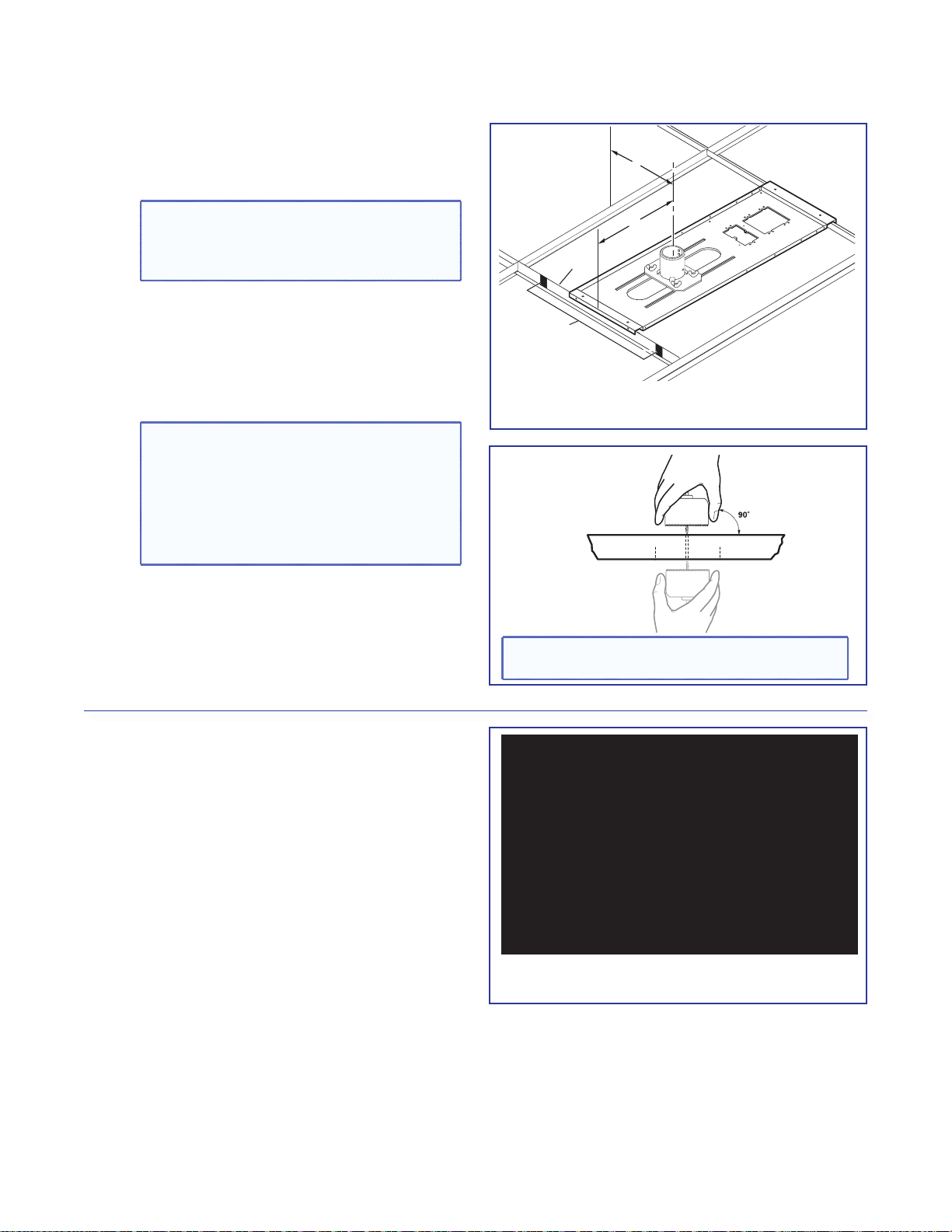
b. Place the PCM 340 over the T-frame, between
the two marks. Lightly tighten the T-frame
securing screws. The T-frame screws can be
used on the outside or the inside to secure the
PCM to the T-frame.
NOTE: Place the PCM 340 on the T-frame
so that the pipe adapter slides left to right
in relation to the proposed screen location,
rather than towards and away from it. This
makes it easier to align and center the
image.
c. Slide the slotted pipe up into the pipe adapter.
Adjust to the desired height and align the
location holes and pipe holes. Insert the location
screw, lightly tightening it down using a
5/32 inch hex wrench. Insert and lightly tighten
down the set screws onto the pipe. Do not
overtighten. The pipe is removed and replaced
later during installation.
Place the PCM 340 on the T-bar
É
Slotted
Pipe
Pipe
Adapter
Align Pipe holes with
location screw holes.
Insert location screw
and secure.
Insert and secure the slotted pipe.
î
PoleVault Digital Systems • Installation — Stage 1 (Screen and Projector)18
Page 25

d. Using a 3/32 inch hex wrench, back out the
set screws on the top portion of the adjuster
plate (see a in the image below) of the UPB 25.
Screw the plate onto the base of the pipe. Align
it so the security flange is at the rear
a
Adjuster
Plate
Pivot Screws
Security Flange
Set Screws (2)
Loosen the four adjuster plate
locking screws and slide the
adjuster plate away from the
projector bracket.
Adjuster Plate
Locking Screws (4)
e. Carefully follow the steps below to install the
projector bracket on the projector.
i. Invert the projector on a flat surface to access
the mounting points. Use a blanket or a
similar item under the projector to protect the
projector and the surface.
ii. On each arm, rotate the barrel (on the end
of the arm) so that it only just protrudes from
the base of the arm (see the figure at right).
iii. Select the correct sized mounting screws and
the appropriately sized washers that fit the
projector mounting point inserts.
iv. To attach the arms to the projector:
The next step is critical as it provides a
flat surface for the bracket to sit on, and
must be done for each mounting point.
• Place a washer on a mounting point
(see the figure at right).
• Position the arm so the barrel is over the
washer.
• Insert the mounting screw down through
the barrel and washer, and into the
threaded insert (mounting point). Lightly
tighten the screw by hand.
b
Projector
Bracket
ï Screw the adjuster plate onto the base of
the pipe.
Rotate the barrel
until it just protrudes
ii
Barrel
below the arm.
ATTENTION:
iv
Ü
Place washer on
mounting point.
Mounting Point
on Projector Base
This is critical as it provides a flat surface
for the bracket to sit on.
NOTE: If using the 3- or 4-millimeter
screws, place an additional small washer
under each screw head, on top of the
barrel, as well as one on the top of the
mounting point.
v. Repeat step iv for all projector mounting
points.
PoleVault Digital Systems • Installation — Stage 1 (Screen and Projector) 19
Place the washer. Align the barrel. Insert the screw.
Page 26

vi. Pivot the arms so that they extend towards
the center of the projector (see the figure at
right). Adjust the arms as needed for your
projector model.
NOTE: Avoid overlapping the arms where
possible.
Washer
vii. With the security flange towards the rear of
vi. Pivot arms towards center of projector.
the projector, place the projector bracket on
top of the arms and adjust for slot alignment.
• Using the slots on the bracket that are
closest to the barrel on each arm, place
the clamp under the arm and lightly secure
it to the bracket with the adjustment screws
(see the figure at right). Loosely secure all
the mounted arms.
Using the slot closest
to the barrel, secure the
arms to the bracket with
the clamp and screw.
NOTE: Where arms are unavoidably
crossed, replace the original adjustment
vii. Secure arms with clamp.
screw with a supplied 10-32 ¾ inch
adjustment screw and secure both
arms to the bracket using one clamp. In
addition, the barrels on the arms must be
raised to compensate, keeping the arms
Where arms cross, use the
supplied screw to secure
both arms to the bracket.
See note at left.
Bracket
level and reducing stress.
Clamp
viii. As close as possible, balance the weight
Arms
Note: If arms cross, secure both with clamp.
of the projector evenly across the projector
bracket. Lift the bracket at opposite corners
to assess if the configuration is approximately
balanced.
ATTENTION: Take into consideration the
uneven weight distribution of the projector
when lengthening or shortening the arms.
Distribute the projector weight evenly on
the arms.
Adjust the bracket on the arms as needed.
The projector shown at right is as close as
possible to being evenly balanced.
PoleVault Digital Systems • Installation — Stage 1 (Screen and Projector)20
viii. Evenly balanced configuration
Page 27

ix. Check for stress on the arms. To do this
Projector
Center Line
⊗
loosen the mounting screws (do not remove).
If the arm or the barrel lifts, this indicates
stress on the arm. Adjust the height of the
threaded barrels to reduce or eliminate
any torque or stress that might be caused
by crossed arms or by projector mounting
points with differing heights. It is important to
keep the arms level and as close (low) to the
projector base as possible.
x. Check that the projector weight is still as
evenly distributed as possible.
Hand tighten the screws until snug.
ATTENTION: Do not overtighten the
mounting screws as this may damage the
projector. See the projector manual for the
threaded insert torque setting.
f. Lift the projector up to the adjuster plate and
slide it into place. Tighten down the locking and
pivot screws.
Loosen the screw and adjust
the barrel height to reduce torque
on the arms and bracket.
Tighten down all the
mounting screws.
Washer
INCORRECT CORRECT
Arm not level, causing stress Arm level, no stress
on mounting point on mounting point
3. Verify the Image Location.
a. Connect a power cable to the projector and
turn it on.
b. Verify image size and location by loosening the
PCM 340 pipe adapter plate wing nuts, and
adjust the plate (left-right) to center the image.
TIP: Remember to include the vertical
and horizontal offsets when aligning the
projector. See the projector manual for
information
c. When satisfied, tighten down the plate wing
nuts.
PoleVault Digital Systems • Installation — Stage 1 (Screen and Projector) 21
Slide and lock the projector onto the
ß
adjuster plate.
Center Line
Measure the
horizontal offset
Lens
Page 28
4. Cut the Ceiling Tile.
T-bar
X"
Y"
Minimum and
Maximum
Throw Distance Marks
a. Mark the location of the PCM 340 on the
T-frame. This aids putting it back in the correct
location when the tile is replaced.
TIP: Mark the screen direction on back
of the tile (for example with an arrow or
“to front”) to help orientation of tile when
replacing it after cutting
b. Measure the distances X and Y (see the figure
at right) from the inner vertical section of the
front and left T-frame runners to the center of
the Pipe Adapter Plate.
Using the X and Y dimensions, mark and cut a
hole for the slotted pipe in the ceiling tile.
TIP: Place the tile on a box and mark the
center of the hole on the underside of the
tile. Use a hole saw bit to start to cut the
hole by hand (turning bit counter clockwise) to avoid damaging the tile. When the
drill bit is through the tile, turn the tile over
and finish cutting from the top side
Take the measurements with the PCM 340
á
on the T-frame.
Top Side of Tile
Underside of Tile
TIP: Mark and start cutting the hole on the
underside. Finish on the top side.
5. Preliminary Safety Hardware Installation
a. Mark and drill holes at 10 degrees out from
vertical for each turnbuckle. Drill a fifth hole
directly centered above the PCM 340 for the
safety cable.
b. Install an appropriate anchor or lag eye bolt for
the structural ceiling into each drilled hole.
à Mark the structural ceiling for lag eye
bolt installation.
PoleVault Digital Systems • Installation — Stage 1 (Screen and Projector)22
Page 29

6. Finish Projector Drop Ceiling Mount
Installation.
a. Detach the projector bracket and projector
from the adjuster plate. DO NOT remove the
projector bracket from the projector.
b. Unscrew the adjuster plate from the mounting
pole.
c. Loosen the pipe adapter set screws on the
PCM 340 and the pipe location screw and
remove the mounting pole, then loosen the
T-frame securing screws and remove the PCM
340 from its marked location.
d. Replace the cut ceiling tile, checking the
orientation to align the hole with the
PCM 340.
e. Replace the PCM 340 over the ceiling tile, slide
the slotted pipe up through the tile and into
the adapter plate. Realign the location holes
with the pipe holes, insert and tighten down the
location screw. Tighten the set screws.
f. Tighten the four T-frame securing screws on the
PCM 340. The T-frame securing screws can be
used on either side of the frame.
J Slide the pipe up through the ceiling tile and
into the pipe adapter plate. Shown as viewed
from below.
PoleVault Digital Systems • Installation — Stage 1 (Screen and Projector) 23
Page 30

7. Secure the Projector Drop Ceiling Mount
to the Ceiling.
a. Attach the four turnbuckles to the base plate,
one at each corner.
WARNING: May result in serious injury.
DO NOT rest or lean on the mounting
plate or suspended ceiling when attaching
turnbuckles, tie wire, or when drilling into
the ceiling.
NOTE: For safest installation, insert the
turnbuckle from the outside so that it
hooks inwards
b. Cut four equal lengths of the supplied hanging
wire, and loop the wire through the anchors or
lag eye bolts, and the turnbuckles, then twist
å Attach the turnbuckles at the corners
of the PCM 340.
the wire around itself at least five times tightly at
each end.
c. Hand tighten the turnbuckles and level the plate
so it just rests on the T-frame.
Secure PCM to T-frame
(from either side)
CAUTIONS:
• The four hanging wires should be taut,
PCM
taking the full weight of the completed
installation.
• Do not overtighten the turnbuckles
T-frame
or the T-frame assembly could be lifted,
making the suspended ceiling bowed
and unsafe
Adjust the turnbuckles to take
up any slack in the hanging wire.
e. Pass the braided safety cable through the fifth
and center anchor and attach it to the center
holes on either side of the plate. Ensure the
K Hand tighten all four turnbuckles.
cable is of equal length on both sides of the
anchor and secure the cable using the cable
clamps.
PoleVault Digital Systems • Installation — Stage 1 (Screen and Projector)24
Page 31

8. Install the Electrical Box (If required).
WARNING: Improper installation may result in
electrical shock or serious injury.
All electrical installation should be performed by
qualified personnel in accordance with local and
national building codes, fire and safety codes, and
local and national electrical codes.
RACO box
If required, the following method is recommended for
integrating a 4S RACO
®
electrical box (not supplied) on
the PCM base plate (for example, a RACO 232, 2 1/8
inch deep, 4x4 inch electrical box and a RACO 778,
1/2 inch raised, 4x4 inch plaster ring or similar).
Install the RACO box on the PCM plate as follows:
a. Attach the box to the plate, using the smallest
notches in opposite corners of the cut-out (see
figure at right). Do not tighten the screws fully at
this time.
b. On the opposite side of the PCM plate, slide
the plaster ring under the screws. The plaster
ring anchors the box in place with PCM plate
sandwiched between.
c. Fully tighten the screws.
WARNING: May result in electrical
shock or serious injury. For safety,
complete all wiring of the electrical boxes
and accessories after the plate is fully
installed and secured.
Use the smallest
notches when
attaching the
RACO box.
RACO 778
Plaster Ring
é Install the RACO box and plaster ring onto
the PCM 340.
d. Mark and cut a hole in the ceiling tile for the
electrical box opening.
9. Install the Screen.
a. Following the guidelines given by the screen
manufacturer, continue to install the screen
mounting brackets and then hang the screen.
TIP: Use S-hooks to hang the screen
from the brackets. Bend the ends of the
S-hooks so the screen does not fall when
it is rolled up.
PoleVault Digital Systems • Installation — Stage 1 (Screen and Projector) 25
Page 32

PoleVault Digital Systems • Installation — Stage 1 (Screen and Projector)26
Page 33

Stage 2:
Audio Input
Mounting the PVT
Wallplate and the
MediaLink Controller
Stage 2 Involves installing and cabling the devices shown below.
NOTE: The installation must conform to national and local electrical codes and UL requirements. See the
device user guide for details.
PVT SW HDMI RGB D AV Source Input Wallplate
PVT SW HDMI RGB D
AUDIO IN
HDMI IN
IR OUT
G
S
LOCAL OUT
Decora
Faceplate
• Where it goes: Installs in a wall near input source location.
• What it does: Transmits an input source HDMI or RGB video and audio signals to the switcher.
NOTES:
• The PVT SW HDMI RGB D is a 2-gang wallplate.
• The PoleVault Digital System incorporate EDID Minder. This allows the transmitter to communicate the
appropriate EDID information to the source, ensuring correct video output resolution.
• The EDID settings on the PVT wallplates are set during switcher configuration. See the PVS 405D
PoleVault Digital Switcher User Guide (available at www.extron.com),or the PCS Help file for setup and
operating details.
AUDIO
IN OUT
VGA IN
Mounting
Screws (4)
Signal/Power
Status LED
Audio and
HDMI input
Connectors
IR Output
Connector
AUDIO IN
HDMI IN
IR OUT
G
S
AUDIO
IN OUT
VGA IN
LOCAL OUT
Audio Output
Connector
VGA Input
Connector
Local Monitor
Output
Audio Input
Connector (at Rear)
PVT Output Port
(at Rear)
L R -
IN
AUDIO
SIG LINK
PVT SW HDMI RGB D
PVT OUT
PoleVault Digital Systems • Installation — Stage 2 (Wallplates and MLC) 27
Page 34

MLS 104 IP Plus MediaLink Controller
PVT SW HDMI D
Audio Input Connector
Mounting
screws (4)
DISPLAY
ON
VOLUME
OFF
CONFIG
VCR
DVD
PC
1
2
3
4
RS-232/IR
COMM LINK
I/O
RS-232
12V
Captive screw connectors for:
Display/RS-232/IR
Comm. Link
Digital I/O,
MLS/RS-232
Power
Tx
DISPLAY
Rx
GROUND
IR OUT
A B C D E
+12V OUT
GROUND
DIGITAL
GROUND
MLS
POWER
IR IN
A B
GROUND
GROUND
+12V IN
CM
SCP
1
2
3
Rx
Tx
LAN
TWEEKER TO REMOVE
PRESS TAB WITH
Ethernet
port
RUN
100
00-05-A6-01-6B-F5
MLC 104 IP PLUS
Right Side
• Where it goes: Installs in a wall at a location convenient to user.
• What it does: Provides remote control of switcher and projector.
Cabling for the Wallplates and MediaLink Controller
PVT transmitter installation
• Sheilded twisted pair (STP) signal transmission cables
(connects PVT input wallplates to PVS 405D switcher)
MLC 104 IP Plus installation
• MLC power and RS-232 control cable
(connects the MLC controller to the MLC control
port on the PVS 405D switcher)
• IR/RS-232 communications cable control cable
(connects the MLC controller to the projector via
RS-232 or to an IR emitter)
• LAN network cable
(not supplied - connects the MLC controller to LAN)
Optional Wallplate
Signal/Power
Status LED
AUDIO IN
HDMI IN
IR OUT
G
S
IR OUT
AUDIO IN
HDMI IN
G
S
AUDIO IN
HDMI IN
Audio and
HDMI input
Connectors
IR Output
Location of
MAC address
AUDIO IN
HDMI IN
HDMI Input
Connector
Rear View
STP201P cable, 35 ft
26-696-35
MLC PW/RS-232, 50 ft
26-626-50
IR Serial Comm, 50 ft
26-621-50
PVT SW HDMI D
SIG LINK
PVT OUT
Decora
Faceplate
Mounting
Screws (4)
PVT Output Port
(at Rear)
• Where it goes: Installs in a wall near input source location.
• What it does: Transmits an input source HDMI and audio signals to the switcher.
PoleVault Digital Systems • Installation — Stage 2 (Wallplates and MLC)28
Page 35

NOTE: The installation must conform to national and local building and electrical codes, and
UL requirements. See the device user guides for details.
1. Install the Mud Rings.
NOTE: These devices can be installed using the
supplied mud ring or a wall box. If installing a
box, allow enough depth for the plate and the
cables. The box should be at least 2.5 inches
(6.4 cm) deep to accommodate the connectors
and cables.
If a suitable wall box is already installed, follow
step 2 onwards.
a. Using an appropriate template or the PVT
mounting enclosure as a guide, with a soft
pencil, mark the area of the wall that will be cut
out.
NOTE: If installing a metal junction box,
check with the manufacturer of the box for
specific installation requirements.
b. Use a jigsaw or small hand saw to carefully
cut away the material within the marked area.
c. If using a mud ring in a wall with insulation
inside, remove at least 6 inches of the insulation
in all directions around the cutout.
NOTE: If a wall stud interferes with
removing 6 inches of insulation around the
cutout, remove the insulation between the
cutout and wall stud.
Wall
Mud Ring
4.00"
3.75"
û Insert the mud ring into the wall.
CAUTION: Risk of personal injury. Smooth
the edges of the opening to avoid
personal injury during installation.
ATTENTION: Smooth the edges of the
opening to avoid damage to the mounting.
d. Insert the mud ring into the opening. The
mud ring locking arms should fit easily into
the opening. If needed, use a saw, file, or
sandpaper to enlarge the hole.
e. Rotate the mud ring locking arms and secure
with the screws provided.
TIP: Use a level when fitting the mud ring.
Repeat steps a to c for each additional input wall
plate that needs to be installed.
f. At the desired location mark the opening for the
MLC 104 IP Plus mud ring.
g. Repeat steps b to e.
PoleVault Digital Systems • Installation — Stage 2 (Wallplates and MLC) 29
Page 36

2. Pull the Cables (at the input locations)
Fasten the WHITE section to the cable
The following cables need to be installed:
• STP cables for signal transmission from the
AV wallplates to the PVS 405D
NOTES:
• Maximum distance from the
PVS 405D to the Wallplate is 150 feet.
• STP cables supplied are terminated to
the TIA 568B standard.
• PoleVault switcher communication cable
from the MediaLink controller (MLC PW/
RS-232/VC, 50 feet, part number
26-626-50)
• Projector communication cables from the
MediaLink controller (IR Serial Comm,
50 feet, part number 26-621-50)
a. Drill cable pathways through any obstructions
(for example, wall caps, fire-breaks, or
horizontal studs).
b. Label the signal cables at both ends with the
supplied labels.
c. Pull the cabling through the wall from the ceiling
space down to the location of the transmitters
and other wall devices, and out through the
openings.
TIP: Secure cables with cable clamps to
provide strain relief.
NOTE:
first, then wrap the clear section around it.
INPUT 1/2
Use the supplied labels for clear cable
É
identification during installation.
PoleVault Digital Systems • Installation — Stage 2 (Wallplates and MLC)30
Pull the cables at each location.
î
Page 37

3. Install the Wallplates.
VGA IN
AUDIO
IN OUT
LOCAL OUT
S G
HDMI IN
AUDIO IN
IR OUT
S
G
Decora
®
Faceplate
Wall
Mud Ring
Extron
PVT SW HDMI RGB D
STP Cable
from PoleVault® Switcher
Audio Input Cable
a. Connect the cables to the rear of the input
devices.
b. If desired, wire an IR emitter to the unit using a
two conductor cable. Wire the ground to G and
signal lead to S. IR signals are transmitted over
the STP cables.
NOTE: For podcasting or recording
applications, use a three conductor audio
cable and connect the audio return to
the connector marked G (ground wire),
R (black wire), and L (red wire). The other
end will be connected to the “Line Out”
connection on the PVS 405D switcher.
This option is available only with
PVT SW HDMI RGB D wallplates.
c. Mount the device into the mud ring, using the
supplied screws.
d. Attach the supplied Decora® faceplate.
e. Label the Decora plate with the supplied label,
using the appropriate input number. This makes
inputs easier to identify when configuring the
switcher.
f. Repeat steps a through e for other AV
wallplates.
Connect the cables to the AV source
Ñ
input devices at each location.
PoleVault Digital Systems • Installation — Stage 2 (Wallplates and MLC) 31
AUDIO IN
HDMI IN
IR OUT
G
S
Mount the PVT in the mud ring then õ attach
ñ
AUDIO
IN OUT
VGA IN
LOCAL OUT
the Decora faceplate.
Page 38

4. Install the MediaLink Controller.
Wire Bared
(22 mm)
Heat Shr
Drain
LAN 2 LAN 3
STPUTAUDIO OUT
5D
GENSO
IN
AUX
VOIC
5
T
1 2
3
OT
DR SHO
R
S
T
G
TIP: Before cabling and installing the
MLC 104 IP Plus, locate the device MAC
address printed on a label on the bottom of
the controller. Write down the 12 character
alphanumeric address, (for example,
00-05-A6-03-9G-H4) and use when
configuring the IP address.
When cabling, the length of exposed wire is
critical to avoid transmission problems. Ensure
the lengths given here are adhered to when
stripping the cables for connection.
NOTE: If a drain wire is used, both ends of the
wire must be covered by heat shrink to avoid
accidental grounding.
a. Connect the MLC power and RS-232 control
cable (part number 26-626-50) as shown at
right. To do this, strip the outer jacket back
to the length appropriate to get the red and
black leads to the switcher power supply. Trim
the white/purple/drain short enough to plug
directly in to the switcher, keeping most of the
drain covered in the jacket.
Wire
ink on
3/16"
(5 mm)
Max.
Heat Shrink on
Outer Jacket to
Inner Conductor
Transition
7/8"
TIP: Observe wire stripping lengths.
PVS 405D
PVS 40
PAGING
PAGIN
SENSOR
R
L
R
VOICELIFT
ELIFT
+V
+V
AUX OVER PVT REMOTE
INPUT 5
L
R
POWER
12V
3A MAX
INPUTS OUTPUT AUDIO OUT
INPUT
1/2
3/4
2
4
SIG LINKSIG LINK
IG
HDMI
IG
PVT IN PVT IN
IN
Included power supply is used for both
PVS 405D and MLC 104 IP Plus
AMPLIFIED AUDIO OUT
AMPLIFIED AUDIO OU
DO NOT
N
ROUN
GROUND
OR SHORT
PEAKE
SPEAKER
UTPUT
OUTPUTS
CLASS 2 WIRING
LASS 2 WIRIN
VER PV
RT
4/8
RS-232
TxRxIRSG G
Rx
AB
MLS PWR
RS-232 12V
8
Ω
Tx
LR
GROUND
GROUND
+12V IN
LAN 1
MLC 104 IP Plus
right side panel
MLS and Power ports
REMOTE
RS-232
Tx Rx G
NOTE:
PVS 405D
Remote RS-232
Port
From MLC 104 IP Plus
terminal
A - (Rx on the MLS port) White (Tx on the RS-232 port)
B - (Tx on the MLS port) Violet (Rx on the RS-232 port)
MLS RS-232 Ground Drain wire
Wire color To PVS 405D terminal
Ground
Power Ground Black To PVS 405D Power Supply
12 V In Red To PVS 405D Power Supply
NOTE:
You must connect
a ground wire between
the MLC and PVS 405D.
G
Ground (Gnd)
B
Receive (Rx)
A
Transmit (Tx)
If you use cable that has
a drain wire, tie the drain wire
to ground at both ends.
Transmit (Tx)
Receive (Rx)
B
A
Tx
Rx
AB
GROUND
MLS PWR
RS-232 12V
MLC 104 IP Plus
right side panel
MLS and
+12V IN
Power
GROUND
ports
G
Ground
+12 VDC input
External Power Supply
(12 VDC, 4 A)
Ground all devices.
NOTE: The MLC 104 IP Plus is powered from the PVS 405D associated power supply.
Connect the MLC 104 IP Plus to the PVS 405D Switcher and Power Supply.
Ü
PoleVault Digital Systems • Installation — Stage 2 (Wallplates and MLC)32
Page 39

b. Connect the IR/RS-232 projector
Connecting IR Cable
k
Connecting RS-232 Cable
LR
DO NOT
GROUND
OR SHORT
SPEAKER
OUTPUTS
4/8
Ω
3A MAX
POWER
12V
HDMI
1/2
SIGLINKSIG LINK
3/4
INPUTS OUTPUT AUDIO OUT
PVS 405D
AMPLIFIED AUDIO OUT
PAGING
SENSOR
PVT IN PVT IN
L
R
AUX OVER PVT REMOTE
VOICELIFT
LAN 1LAN 2LAN 3
INPUT 5
+V
L
R
RS-232
TxRxIRSG G
123
GROUND
+12V OUT
CM
GROUND
IR OUT
GROUND
SCP
GROUND
Tx
Rx
DISPLAY
RS-232/IR
A B C D E
COMM LINK
LAN
PRESS TAB WITH
TWEEKER TO REMOVE
A B
MLS
RS-232
POWER
12V
DIGITAL
I/O
IR IN
Tx
GROUND
Rx
+12V IN
MLC 104 IP Plus Right Side Panel
CAT 5, 5e or 6 Cable
PVS 405D
NOTE: Connect to the PVS 405D Ethernet ports as follows:
1. TCP/IP network
2. MLC controller
3. Optional Network Device
TCP/IP
Network
communication cable as shown for either
RS-232 or IR projector control
NOTE: Some projectors require NULL
connection wiring, which inverts the Tx
and Rx connections. See the projector
guide for details.
IR control for a connected input device such as
a Blu-ray player can be made through the PVT
wallplate (see the figure at step 4d).
Terminal RS-232 Cable color Pin
Tx White 2
Rx Violet 3
Ground
Shield 5
Terminal IR/RS-232 Cable color IR Cable color
Ground Black Black
IR Signal Red White/Black
c. Connect a network cable (CAT 5, 5e, or 6
straight through) from the PVS 405D to the
RJ-45 LAN jack on the MLC.
The switcher acts as a 3-port Ethernet switch,
when connected to the LAN.
Projector
Projector
IR Emitter
White
(or striped)
Black
MLC IR/RS-232
Tx
Rx
DISPLAY
RS-232/IR
Comm Cable
Shield
IR OUT
GROUND
NOTE: White, violet, and
shield not used.
RedBlack
Tx
Rx
IR OUT
GROUND
DISPLAY
RS-232/IR
Red
9-Pin Female
NOTE: Red and black
not used.
White
Violet
MLC 104 IP Plus
Connect the MLC to the projector with an
á
RS-232 cable or IR emitter cable, as appropriate.
Blac
Connect to the LAN using a CATx cable.
ó
PoleVault Digital Systems • Installation — Stage 2 (Wallplates and MLC) 33
Page 40

d. The connections between the MLC 104 IP Plus
and the PVS 405D switcher should look like the
figure below.
POWER
12V
3A MAX
STP Input Cable
Projector
DISPLAY
ON
VOLUME
RGB IN #2
HDMI IN #1
AUDIO
AUDIO IN
IN OUT
HDMI IN
VGA IN
LOCAL OUT
IR OUT
S
G
INPUTS OUTPUT AUDIO OUT
1/2
SIG LINK SIG LINK
3/4
PVT IN PVT IN
RS-232
VCR
OFF
1
DVD
2
PC
3
CONFIG
4
Tx
MLC 104 IP PLUS
Rx
DISPLAY
RS-232/IR
Optional PVT Front Panel
IR Output Connection
HDMI
Ground
Rx
Tx
IR OUT
+V OUT
GROUND
A B C D E
COMM LINK
IR Emitter
GROUND
PVS 405D
PAGING
SENSOR
L
R
VOICELIFT
+V
INPUT 5
L
AUX OVER PVT REMOTE
R
IR control
Tx
Rx
IR OUT
GROUND
DISPLAY
RS-232/IR
PRESS TAB WITH
TWEEKER TO REMOVE
LAN
2
3
1
Tx
Rx
CM
SCP
IR IN
A B
+12V IN
GROUND
GROUND
GROUND
MLS PWR
DIGITAL
RS-232 12V
I/O
Rx
AB
MLS PWR
RS-232 12V
To Blu-ray (or similar) input device
S
IR Out
Ground
G
RS-232
Ground (Gnd)
G
Ground
+12 VDC input
Transmit (Tx)
Receive (Rx)
Receive (Rx)
A
Transmit (Tx)
B
Tx
MLC 104 IP Plus right side panel
+12V IN
GROUND
GROUND
MLS and Power ports
AMPLIFIED AUDIO OUT
DO NOT
GROUND
OR SHORT
SPEAKER
OUTPUTS
CLASS 2 WIRING
RS-232
IR
Tx Rx
SG G
Tx
Rx
LAN 1 LAN 2 LAN 3
4/8
Ω
LR
NOTES:
• You must connect a ground wire
between the MLC and PVS.
• If you use cable that has a drain
wire, tie the drain wire to ground at
both ends.
To Supplied
PVS Switcher
Power Supply
(12 VDC, 4 A)
Connections made to the MLC 104 IP Plus
ò
e. Sliding the cables into the opening, secure
the MLC 104 IP Plus to the mud ring with the
provided machine screws.
Wall
Mud Ring
OFF
OFF
ON
ON
Extron
MLC 104 IP Plus
VOLUME
DISPLAY
CONF
IG
MLC 104 IP Plus
1
2
3
4
ô Secure the MLC 104 IP Plus to the mud ring.
PoleVault Digital Systems • Installation — Stage 2 (Wallplates and MLC)34
Page 41

Stage 3:
)
Installing the FF 120
Ceiling Speakers
Stage 3 Involves installing the devices shown below.
FF 120 Flat Field Ceiling Speakers
FF 120 Speaker (2)
Terminal Cover
Seismic Tabs (3 per side)
Anchor Rings (2)
T-rails (2)
• Where it goes: Installs in ceiling tiles at a predetermined location for best acoustics.
Connects to the switcher.
• What it does: Receives and outputs audio signal from the PVS 405D switcher.
Cabling for the Speakers
Speaker Installation:
• Speaker cable (connects ceiling speakers to the
PVS 405D switcher).
Cable Clamps (2
SPK 18, 35 ft
PoleVault Digital Systems • Installation — Stage 3 (Speakers) 35
Page 42

NOTE: The installation must conform to national
and local electrical codes, and UL requirements.
See the device guide for details.
1. Cut Ceiling Tile.
a. Remove the ceiling tiles where the speakers are
to be installed.
TIP: For ease of working on the speaker
when it is replaced on the T-frame, remove
adjacent tiles.
b. Mark a line 12 inches from one of the short
sides of the tile and cut along the line. Discard
the short portion.
TIP: Use a fine hacksaw blade to cut the
tile without damaging the face. Place an
empty box under the tile for support and
to collect the waste.
2. Install the Speaker on the Drop Ceiling.
a. At the speaker location, lay one of the supplied
T-rails 12 inches from one end of the T-frame.
The speaker is placed into the small section.
b. Remove the terminal cover from the rear of a
speaker and attach the anchor ring and cable
clamp to the cover.
c. Place the speaker onto the T-frame and,
passing the speaker cable through the cable
clamp on the terminal cover, connect the
speaker wires to the speaker terminals:
• Red wire - positive (+)
• Black wire - negative (-)
Mark and cut the tile.
Å
Ç Place the T-rails on the T-frame.
ATTENTION: DO NOT short the
speaker wires together as it may
damage the speakers.
d. Reattach the terminal cover.
e. Bend the seismic tabs over the T-rails.
f. Replace the ceiling tile.
PoleVault Digital Systems • Installation — Stage 3 (Speakers)36
Remove terminal cover and attach clamp
É
and ring.
36
Page 43

Repeat steps 1 and 2 for each speaker that
Seismic Safety
Cable
Anchor this end to a
lag eye bolt screwed
into the structural ceiling.
Route the safety cable
through the anchor ring
and the seismic tab.
needs to be installed, connecting the speakers
according to the system preferred (for example,
in parallel, see page 38).
If you wish to install an optional seismic/
safety cable, at each speaker location do the
following:
g. Mark, drill, and install a lag eye bolt for the
seismic safety cables (not included) in the
structural ceiling above the speaker location.
h. Pass the seismic cable through the anchor
ring, down to the seismic tab and twist the end
around the cable five times. Pass the other end
up through the lag eye bolt and twist it around
the cable five times.
To wire the speaker, see the next page.
Attach safety cable.
M
PoleVault Digital Systems • Installation — Stage 3 (Speakers) 37
Page 44

3. Terminate the Speaker Cable for the PVS
8 Ohm Load
LR
8 Ohms
AMPLIFIED OUTPUTS
Mono –
Mono +
Mono –
Mono +
4 Ohm Total Load4 Ohm Total Load
Two 8 ohm speakers
wired in parallel
equal a 4 ohm load.
LR
4/8 Ohms
AMPLIFIED OUTPUTS
Mono –
or
Stereo R-
8
ohms
8
ohms
Mono +
or
Stereo R+
Mono –
or
Stereo L-
Mono +
or
Stereo L+
8
ohms
8
ohms
8 Ohm Load
Stereo R–
Stereo R+
Stereo L–
LR
8 Ohms
AMPLIFIED OUTPUTS
Stereo L+
PVS Switcher
Rear Panel
LR
4/8
Ohms
AMPLIFIED OUTPUTS
4-pole Captive
Screw Connector
(viewed from top)
Audio output
to speakers
Switcher.
a. To terminate the cable, strip the end of the
cable 0.2 inch (5 mm) and secure the wires into
the supplied 4-pole captive screw connector.
ATTENTION: DO NOT short the speaker
wires together as it may damage the
switcher.
NOTE: The correct speaker impedance
loading must be observed when setting up
a speaker system. See figures below for
examples.
Speaker
Wire color
To PVS 405D terminal
(Left and Right)
Red Positive (+)
Black Negative (-)
Ñ Wire the captive screw connector.
Stereo output
Dual mono output
Stereo or dual mono output using parallel speaker wiring
NOTE: By default, the amplifier is set for dual mono output. Use the software or Extron Special Instruction Set
(SIS) commands to change the setting to stereo if desired. For full details, see the PVS 405D User Guide,
available online at www.extron.com.
PoleVault Digital Systems • Installation — Stage 3 (Speakers)38
Page 45
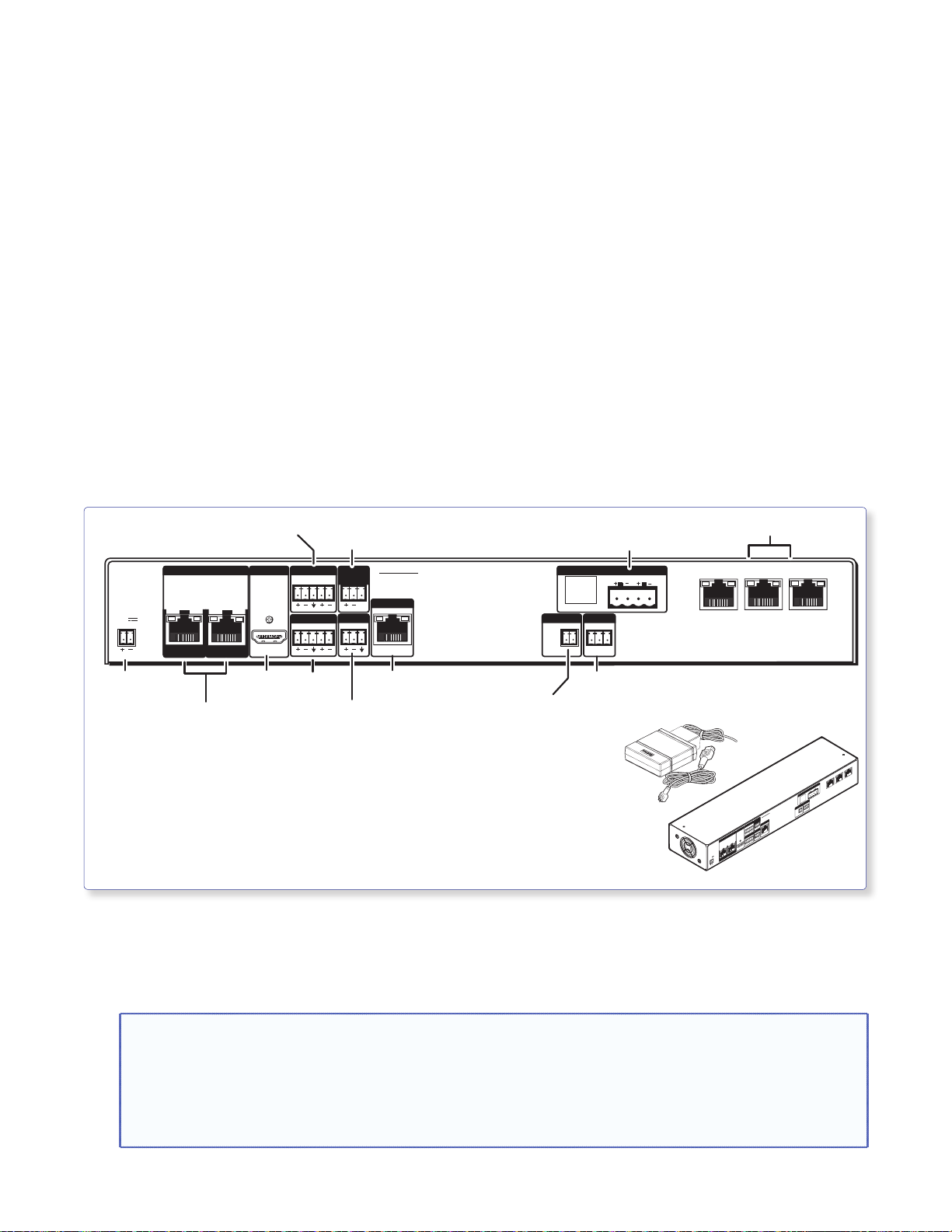
Stage 4:
Power Supply
3-Port 10/100
Installing the Switcher
Mounting System and
the PVS 405D
Stage 4 Involves installing the switcher mounting system and the PVS 405D Digital Switcher.
This stage is divided into four sections based on the system type. Each system mounts the PVS 405D
switcher and associated power supply using a specific mounting kit.
A. PoleVault System (using the PMK 560 Pole Mount Kit)
B. WallVault Wall Mount System (using the WMK 160 Wall Mount Kit)
C. WallVault Short Throw System (using the USFM 100 Short Throw Wall Mount Kit)
D. PlenumVault System (using the PVM 220 PlenumVault Mount Kit)
The PVS 405D Digital Switcher.
INPUTS OUTPUT AUDIO OUT
1/2
POWER
12V
3A MAX
SIG LINK SIG LINK
PVT IN PVT IN
Connector
HDMI/RGB Video and Audio
Inputs (1-4) from
Lineout
Output
3/4
HDMI
HDMI
Output
Paging Sensor
L
R
INPUT 5
L
R
Aux Audio
Input 5
Input
Port
PVS 405D
PAGING
SENSOR
VOICELIFT
+V
AUX OVER PVT REMOTE
SG G
VoiceLift
Receiver Port
Aux
IR Control
Input
Speaker
Output
AMPLIFIED AUDIO OUT
RS-232
Tx Rx
4/8
Ω
LR
DO NOT
GROUND
OR SHORT
SPEAKER
OUTPUTS
IR
RS-232
Control Port
PVT SW HDMI RGB D
• Where it goes: PVS 405D and power supply install into a mounting
enclosure.
• What it does: Receives input video and audio signals from AV source
input wall plates. Outputs and switches the video and
audio signals to a display device (such as a projector or
flat screen display) and ceiling speakers.
For installation of the PMK 560 for the PoleVault system, start at page 40.
For installation of the WMK 160 for the WallVault Wall Mount system, start at page 44.
For installation of the USFM 100 for the WallVault Short Throw system, start at page 47.
For installation of the PVM 220 for the PlenumVault system, start at page 52.
Ethernet Switch
LAN 1 LAN 2 LAN 3
Rear View
AMPLIFIED AUDIO OUT
DO NOT
GROUND
OR SHORT
SPEAKER
OUTPUTS
REMOTE
RS-232
IR
OVER PVT
TxRx
SG G
PVS 405D
PAGING
SENSOR
VOICELIFT
R
AUDIO OUT
+V
L
OUTPUT
AUX
R
INPUT 5
INPUTS
HDMI
L
3/4
1/2
SIG LINK SIG LINK
PVT IN
POWER
12V
PVT IN
3A MAX
LAN 1 LAN 2 LAN 3
L R
4/8
Ω
NOTES:
• The installation must conform to national and local building and electrical codes, and UL requirements.
See the device user guide for details.
• The included power supply MUST NOT be installed in wall cavities or similar locations.
• Unless installing the PVM 220 (for the PlenumVault System only) the power supply MUST NOT be
installed above the suspended ceiling.
PoleVault Digital Systems • Installation — Stage 4 (Mounting System Kit and PVS 405D) 39
Page 46

A. PoleVault System (PMK 560 Pole Mount Kit)
A
Mounting Plate
Base Plate
To open, remove 4 cover screws
and slide the covers away.
PMK Covers (2)
• Where it goes: Attaches to slotted pipe, above the projector and close to the drop ceiling.
• What it does: Supports and hides the installed PVS 405D switcher and power supply from view.
A1. Install the PMK 560 Base Plate.
a. Remove the four cover screws from the center
of the PMK 560 and slide the two halves apart.
Remove them from the base plate.
ttach PMK to the projector
pole. Secure the pipe collar
with the four
10-32 set screws.
1d1f1e
1c
Attach
Power
Supply
NOTE: If the PoleVault switcher and its power
supply are already installed, go directly to
step 1d.
b. To mount the PoleVault switcher, place the
mounting plate, with the raised tabs upwards,
on the top surface of the switcher and pass the
two supplied 4-40 x 3/16 inch screws into the
top of the switcher (see figure at right). Secure
Hook the combined mounting
plate and switcher into the
base plate and secure with
screws.
1b
Attach the mounting plate
to the top of the
PoleVault switcher.
Projector
Pole
the mounting plate but do not overtighten.
Use only the supplied screws to avoid
IN
P
POWER
damaging the switcher.
c. Attach the associated power supply to the base
plate with the supplied tie wraps by passing
them through the appropriate slots and around
the power supply. Tighten until snug
PVS 405D
Switcher
U
TS
12V
3
A
MAX
1/2
SIG
OUTPUT
LINK
3/4
S
AUDIO OUT
I
G
L
INK
L
HDMI
PVT IN
PAGING
R
SENSOR
PVS 405SA IP
PVT IN
INPUT 5
L
+V
R
VOICELIFT
AUX
AMPLIFIED AUDIO OUT
DO N
GROU
OT
OR SH
ND
SPEAKER
ORT
OUTPUTS
L R
OVER PVT
4/8
Ω
IR
REMOTE
RS-232
LAN 1 LAN 2 LAN
S
G
TxRx
G
3
d. Loosen the four pipe collar set screws and slide
the base plate up the pipe until it is touching the
suspended ceiling.
e. Level the base plate and secure it by fully
tightening the set screws.
Attach the mounting plate to the switcher,
Å
û
fasten the power supply to the base plate, ü secure
the base plate to the projector pole,
and hook
°
mounting plate tabs into the base plate.
NOTE: At least three set screws must come in contact with the pipe.
PoleVault Digital Systems • Installation — Stage 4 (PMK 560 and PVS 405D)40
Page 47

f. Hook the combined plate and switcher into
om
the PMK 560 base plate (see figure on page
40, °). Secure it to the base plate with two
screws.
ATTENTION: Use only supplied screws to
avoid damaging the switcher.
A2. Pull the Cables (at the switcher location).
a. Gather all the cables from the speakers, AV wall
plates, MLC 104 IP Plus controller, network,
and any installed optional devices that have
been run to the switcher location. Pull them
down through the ceiling hole and the pipe.
These cables are:
• MLC power/RS-232 cable
• STP AV input cables from the wall plates
• Speaker cables
• MLC to projector (IR/RS-232 projector
control) cable
• LAN cables
• Any optional device cables (Aux audio
input Priority Page Sensor Kit, VoiceLift)
b. Pull the cables out of the pipe slot towards the
switcher, ready for connection. Leave the
IR/RS-232 projector control cable to hang out
of the bottom of the pipe.
c. Connect the HDMI output video signal cables
to the switcher and pull the loose ends down
the pipe so that they hang out the pipe with
the IR/RS-232 projector control cable, to be
connected to the projector later.
NOTE: Do not thread any high voltage
power cabling, such as power supply
or projector power cords, through the
projector pipe. This violates National
Electrical Code.
Cables to PVS 405D
AV wall plate cables, STP
1
MLC 104 IP Plus switcher control cable
2
3
FF 120 speaker cables
4
LAN cable(s)
IR projector control cable (from MLC)
5
1
4
1
5
3
3
2
Optional accessory cables fr
the VoiceLift and Page Sensor,
may also be included.
INPUTS
POWE
12V
R
3
A MAX
1/2
SIG
OUTPUT
LINK
3/4
SIG
AUDIO OUT
L
INK
L
HDMI
PVT IN
PAGING
R
SENSOR
PVS 405SA IP
PVT IN
INPUT 5
L
+V
R
VOICELIFT
AUX
1
6
2
AMPLIFIED AUDIO OUT
DO NOT
GR
O
OR SHORT
UND
SPEAKER
OUTPUTS
L R
OVER PVT
4/8
Ω
3
IR
REMOTE
RS-232
LAN 1
S
G G
TxRx
LAN 2
5
LAN
3
4
Cable Access
Slot
Cables to Projector
6
HDMI cable
6
To Projector
Switcher and Projector Cable Overview
PoleVault Digital Systems • Installation — Stage 4 (PMK 560 and PVS 405D) 41
Page 48

A3. Secure the HDMI Cables Using the LockIt
Bracket.
The supplied Extron LockIt lacing bracket makes
it possible to secure a standard HDMI cable to the
PVS 405D switcher.
NOTE: The tie wrap can be tightened using
pliers or similar tools.
To securely fasten an HDMI cable to the PVS 405D:
a. Plug the HDMI cable into the rear panel HDMI
connector.
b. Loosen the HDMI connection mounting screw
from the rear panel enough to allow the LockIt
lacing bracket to be placed over it. The screw
does not have to be removed.
c. Place the LockIt lacing bracket on the screw
and against the HDMI cable connector.
d. Tighten the screw to secure the bracket.
e. Place the included tie wrap around the HDMI
connector and the LockIt lacing bracket and
tighten as shown in the images at right.
OUTPUT
3
b
a
c
LLLLLLL
d
3
e
Secure HDMI Cable with LockIt Bracket
PoleVault Digital Systems • Installation — Stage 4 (PMK 560 and PVS 405D)42
Page 49

A4. Finish Installing the Mounting Kit.
Line Out
Supplied PVS Switcher
Exter
(12 VDC, 4 A max.
(12 VDC, 4 A max.)
CAUTION: The PoleVault signal transmission method is specific for PVS 405D switcher working
with PVT wallplates. DO NOT connect the input ports to an MTP system or to an LAN or data
transmission system.
a. Connect the cables as follows to the switcher:
a PVT SW HDMI RGB D Input wall plate (STP) cable
b Audio input 5 cable (optional)
c Aux input cable (optional)
d VoiceLift Receiver cable (optional)
e Paging sensor cable (optional)
f HDMI output cable
g Audio line out cable to an assistive or recording
device (optional, see audio warning card for details)
Your completed connections should look like the image below.
7
L
R
INPUT 5
L
R
Aux Audio
Input 5
Paging
Sensor
+V
5
PVS 405D
PAGING
SENSOR
VOICELIFT
+V
AUX OVER PVT REMOTE
4
Aux
VoiceLift
Input
Receiver
POWER
12V
3A MAX
12
Power Connector
nal Power Supply
)
Output (Audio)
INPUTS OUTPUT AUDIO OUT
1/2
3/4
AUDIO
IN OUT
VGA IN
LOCAL OUT
HDMI
6 2 3
HDMI
Connector
HDMI Output
to Display Device
SIG LINKSIG LINK
PVT IN PVT IN
1
HDMI/RGB
AUDIO IN
HDMI IN
IR OUT
S
G
PVT SW HDMI RGB D
HDMI or RGB video/audio, Inputs1/2 and 3/4
1 STP cable with RJ-45 connectors
h Audio output to speakers (see page 38)
i Control cable from MLC 104 IP Plus
j IR control cable
k LAN 1: TCP/IP Network
LAN 2: MLC Controller
LAN 3 Optional network device
l Power supply. Do not apply power yet.
Audio Output to Speakers
PVS terminal
Speaker
(left and right)
wire color
Red Positive (+)
Black Negative (-)
AMPLIFIED AUDIO OUT
DO NOT
GROUND
OR SHORT
4/8
SPEAKER
OUTPUTS
RS-232
IR
Tx Rx
SG G
10
SG
IR control
8
LR
Ω
MLC 104 IP Plus
9
RS-232 input
NOTE: You must connect
a ground wire between
the MLC and PVS.
G
Ground (Gnd)
B
Receive (Rx)
A
Transmit (Tx)
NOTE: If you use cable that has
a drain wire, tie the drain wire
to ground at both ends.
3-port 10/100 Ethernet Switch
LAN 1 LAN 2 LAN 3
MLC
wire color
White Tx on RS-232 port
Violet Rx on RS-232 port
Drain wire Ground (G)
Black Power Supply (–)
Red Power Supply (+)
Transmit (Tx)
B
Receive (Rx)
A
Tx
Rx
AB
+12V IN
GROUND
GROUND
MLS PWR
RS-232 12V
Connect to ports as follows:
1. TCP/IP network
2. MLC controller
3. Optional network device
11
To PVS terminal
B
Ground
+12 VDC input
MLC 104 IP Plus right side
panel MLS and Power ports
To Supplied
PVS Switcher
Power Supply
NOTE: The cabling of the PoleVault Switcher is the same regardless of which switcher mounting kit used.
PoleVault Digital Systems • Installation — Stage 4 (PMK 560 and PVS 405D) 43
Page 50

B. WallVault System (WMK 160 Wall Mount Kit)
Se
M
)
"
Ass
v
o
M
lat
e
K
(4) 1/4" KapToggle®
(4) 1/4
Assemblies
4
(4) 1/4-20 x 2"
Pan Head Bolts
(2) #14 x 1 3/4"
2) #14
Self-tapping
Metal/Wood Screws
(4) Cover Screws
Co
(1) WMK 160 Base Plate
(1) WMK 160 Cover
• Where it goes: Installs onto a wall close to the projector.
• What it does: Supports and hides from view the installed PVS 405D switcher, power supply, and any
1) WM
160 Base P
(1) PoleVault Switcher
(1) P
Mounting Plate
installed optional accessories.
B1. Install the WMK 160 Base Plate
NOTES:
• For masonry wall use steps a to e.
• For non-masonry walls use steps f to j.
WMK 160
Base Plate
Mounting
Holes
Level
Cutout for
Electical Outlet
Marker for
Pilot Hole
a. To mount the WMK 160 onto masonry
walls, hold the base against the wall, level it,
and mark the positions of four slotted mounting
holes (indicated by + marks in the figure at
right). Set the base plate aside.
b. Using a masonry drill bit, drill 1¾ inch (4.4 cm)
deep pilot holes at the marked locations.
c. Screw in ¼ x 1¾ inch masonry screws (not
supplied) until a gap of about 3/8 inch (9 mm)
remains between the wall and the screw heads.
d. Align the slotted mounting holes of the base
plate over the installed screws, then slide the
plate down so the screws fit into the slots.
e. Verify level and position and tighten all the
Cutout for Signal Cable Access
screws to secure the plate flush to the wall.
Proceed to step B2.
Mounting the base plate on a masonry wall.
PoleVault Digital Systems • Installation — Stage 4 (WMK 160 and PVS 405D)44
Page 51

f. To mount the WMK 160 onto non-masonry
Marker for
walls, at the desired site, locate and mark the
wall studs.
NOTES:
• For ideal installation secure the base plate
to at least one wall stud
• Drywall KapToggles can be used for holes
not aligned with studs.
• Always use the widest spacing of screws
and KapToggles.
• The base plate can be installed over an
existing electrical outlet.
g. Hold and level the base plate against the wall
and mark the positions of the slotted mounting
holes that are on the stud lines (see image at
right). Where applicable, mark the mounting
holes on the wall for drywall toggles.
h. If the cables are to be run behind the wall to the
WMK 160 location, mark the cutout area on the
wall for the signal cable access hole and cut out
the marked area.
i. Drill 1¾ inch (4.4 cm) deep pilot holes at the
hole marks.
j. At the pilot holes, screw in the screws until a
gap of about 3/8 inch (9 mm) remains between
the wall and the screw heads.
k. Align the slotted mounting holes in the base
plate over the installed screws, then slide the
plate down so the screw fit into the slots.
l. Verify level and position, and tighten down all
the screws to secure the plate flush to the wall.
NOTE: If using toggle assemblies, see figure at
right for method.
Mounting
Holes
Cutout for
Electrical
Outlet
Level
Pilot Hole
WMK 160
Base Plate
Wall Studs
Cutout for Signal Cable Access
Mounting the base plate on a non-masonry wall.
b. Slide plastic washer
down into pilot hole.
c. Cut off handle close to wall.
d. Hand screw in pan head
bolt until 1/8" gap remains.
Toggle Assembly Installation
B2. Install the Switcher Onto the Base Plate.
a. Place the switcher (base up) on a flat surface.
Place the mounting plate flat on the switcher
base with the plate tabs (raised section up)
over the edge of the front panel. Align the two
mounting holes in the switcher base with the
corresponding holes on the mounting plate.
Secure the plate to the switcher with the
supplied 4-40 x ¼ inch screws.
b. Secure the switcher mounting plate (with
switcher attached) to the base plate by sliding
the two tabs into the slots at the bottom edge
of the base plate. Secure to the standoffs with
4-40 x 3/16 inch screws.
PoleVault Digital Systems • Installation — Stage 4 (WMK 160 and PVS 405D) 45
b
(2) 4-40 x 3/16"
screws
3
2 LAN
1 LAN
N
LA
G
Rx
x
T
TE
-232
R
G
T
RS
MO
S
U
O
RE
Ω
L
IO
8
/
R
T
4
D
I
TS
V
R
E
P
T
K
AU
R
TPU
O
D
D
OU
N
SH
VER
SPEA
OT
O
IFIE
N
OR
L
GROU
O
D
AMP
IFT
L
E
IC
VO
X
5SA IP
AU
+V
40
R
PVS
T 5
G
SOR
U
N
P
L
IN
IN
SE
PAG
R
T
I
L
IN
IO OU
T
M
D
V
P
HD
AU
K
N
T
I
L
U
P
T
T IN
U
V
4
G
/
O
P
I
3
K S
N
I
L
2
G
S
I
1/
S
T
PU
IN
X
A MA
ER
V
3
2
1
OW
P
(2) 4-40 x 1/4"
screws
a
Attach switcher to the mounting plate and secure
both to the base plate.
Page 52

c. Secure the power supply to the right of the
V700
electrical outlet cutout by threading the supplied
tie wraps through the loops on the base plate.
Attach it so the cables are easily and safely
routed to the electrical outlet and switcher alike.
d. An optional ¼ rack, 3 inch deep accessory
device, such as the Extron IPL T S2, can be
installed on the WMK 160 base plate. To do
so, remove the base plate from the wall and
place the device towards the top of the base
plate, align the holes on the base plate and the
device, and secure with the supplied 4-40 x
3/16 inch screws. Replace the base plate.
B3. Run the Cables to the WMK 160 Location.
Run signal cables from the proposed PVT input
wallplates, control device location, and the speakers to
the WMK 160 location. Cables can be routed to
WMK 160 either behind the walls, or through a surface
raceway (for example, Wiremold® V700 or 2400 series).
2400
Raceway Option
Electrical Access
Cutout
a. If running cable behind the walls, run all the
cables from the various locations to the WMK and
through the access cutout.
b. If using a surface raceway, slide the WMK
cover over the base plate, then identify and mark
the most suitable raceway entrance to the
WMK 160.
Run the raceway from the signal source,
speaker, and display locations to the marked
raceway entrance at the WMK.
Remove the WMK cover, and remove the
desired knockout.
Attach the raceway to the wall. Run cables from
the sources and outputs through the raceway
Signal Cable
Access Cutout
Cabling Run Options
to the WMK.
B4. Cable the Switcher.
Connect the cables to the switcher as shown on
pages 43.
NOTE: If using a device other than a PVS 405D
(for example, PVS 305SA IP), refer to the specific
device guide for details.
CAUTION: The WallVault signal transmission
method is specific for PVS 405D switcher working
with PVT wallplates. DO NOT connect the input
ports to an MTP system or to an LAN or data
transmission system.
B5. Final Installation.
Place the cover onto the WMK 160 base plate and
tighten down the screws to secure the cover.
PoleVault Digital Systems • Installation — Stage 4 (WMK 160 and PVS 405D)46
Page 53

C. WallVault System (USFM 100 Short Throw Wall Mount Kit)
Plastic Enclosure Cover
Boom Arm
Base Plate
Arm Cover (bottom)
Arm Cover (top)
Arm Cover (front)
Device Mounting Plate
Cutout for
Marker for
USFM 100
Mounting
• Where it goes: Installs onto a wall close the short throw projector location.
• What it does: Supports the short throw projector and hides from view the installed PVS 405D switcher,
power supply, and any installed optional accessories.
WARNING: Before commencing installation, the wall structure must be examined to determine if it is suitable for the
proper installation and support of this product. If needed, the installer should reinforce the wall. Drywalls should
have a minimum thickness of 1/2 inch and a maximum thickness of 5/8 inch.
Improper installation of this product could lead to serious injury.
NOTE: Before installation, see the user manual for the display device to determine the proper location and placement
of the mount. Take into consideration the projector lens offset, screen size, screen aspect, and projected image throw
distance. See the USFM 100 specifications (available at www.extron.com) for the dimensions of the USFM 100 to aid
in this determination.
Base Plate
Signal Cable
Level
Pilot Hole
Holes
Access
USFM 100 Base Plate.
PoleVault Digital Systems • Installation — Stage 4 (USFM 100 and PVS 405D) 47
Page 54

C1. Install the USFM 100 Base Plate.
Marker for
Mounting
NOTES:
• It is required to attach the base plate to two wall studs, using a minimum of four securing points
• Drywall KapToggles can be used for holes not aligned with studs.
• Always use the widest spacing of screws and KapToggles.
• The base plate can be installed over an existing electrical outlet.
a. To mount the USFM 100 onto non-masonry
walls, at the desired site, use an edge-to-
edge stud finder to locate the center of the wall
studs (wood or steel). Mark each stud location.
Minimum joist size should be 2 by 4 inches.
Pilot Hole
Holes
b. Hold and level the base plate against the wall.
Mark a minimum of four positions (two top, two
bottom) using either the mounting slots or the
keyholes (slots uppermost) that are on the stud
lines. Where applicable, mark the mounting
holes on the wall for drywall toggles.
c. If the cables are to be run behind the wall to the
USFM 100 location, mark the cutout area on
Cutout for
Signal Cable
Access
the wall large enough for signal cables.
d. Remove the base plate and set it aside. Cut out
the marked area for cable access.
For drywall with wood studs
i. Drill ¼ inch diameter pilot holes at the marked
Signal Cables
Exiting from
Cutout
stud locations.
ii. Align the base plate mounting holes over the
pilot holes and lightly secure with 5/16 inch lag
screws and washers.
iii. Verify level and position, and fully tighten down
all the screws to secure the plate.
Cut out a Cable Access Area
For drywall with steel studs
i. Drill a ½ inch (13 mm) hole through the stud at
each of the locations (four recommended).
ii. Insert the supplied toggles through the studs
and lightly secure the plate using the four
supplied (¼-20 x 2 inch) bolts and washers.
iii. Verify level and position, and fully tighten down
all the bolts to secure the plate flush to the wall.
C2. Install the Switcher Onto the Base Plate.
a. Place the mounting plate flat on the switcher
base with the two small raised tabs on top, and
the small securing tab over the front panel. Align
the two mounting holes in the switcher base
with the corresponding holes on the mounting
plate. Secure the plate to the switcher using the
two 4-40 x ¼ inch pan head screws.
PoleVault Digital Systems • Installation — Stage 4 (USFM 100 and PVS 405D)48
c. Cut off handle close to wall.
Toggle Assembly Installation
b. Slide plastic washer
down into pilot hole.
d. Hand screw in pan head
bolt until 1/8" gap remains.
Page 55

iv. Secure the mounting plate (and switcher) to
3
w
2400
the base plate by aligning the two small tabs
on the back of the mounting plate over the
corresponding tabs on the base plate (see
figure at right). Slide the mounting plate (and
switcher) down into place. Secure it to the
base plate by passing a 6-32x¼ inch screw up
through the securing tab (see figure at right).
Tighten down the screw.
C3. Run the Cables to the USFM 100 Lcation.
Run signal cables from the PoleVault input
wallplates, control device location, and the speakers
to the USFM 100 location. Cables can be routed
behind the walls, through a surface raceway (such
as Wiremold 700 or 2400), or through conduit
directly to the USFM 100.
If running cable behind the walls:
Run all the cables from all the locations to the USFM
100 and through the access hole (cut in step C1d).
If using a surface raceway or conduit:
i. Turn over the left or right cover as needed, and
from the inside, cut the most suitable marked
raceway or conduit knockout for the cable to
enter the USFM 100. Remove the knockout.
ii. Run the raceway or conduit from all locations
to the marked entrance and attach to the
baseplate.
USFM 100 Base Plate
(2) 4-40 x 1/4"
Screws
Mounting Plate
Securing
Tab
PVS 405D
Switcher
2 LAN 3
1 LAN
N
A
L
G
xRx
T
TE
-232
R
G
T
RS
MO
S
U
O
RE
Ω
L
IO
8
/
T
4
D
IR
TS
V
R
E
P
T
K
AU
R
TPU
O
D
D
OU
N
SH
VER
SPEA
OT
O
N
OR
LIFIE
GROU
O
D
AMP
IFT
L
E
IC
VO
X
5SA IP
V
AU
+
40
R
PVS
T 5
G
SOR
U
N
P
L
IN
IN
SE
PAG
R
T
I
L
IN
IO OU
T
M
D
V
P
HD
AU
K
N
T
I
L
U
P
T
T IN
U
V
4
G
/
O
P
I
S
3
K
N
I
2
G L
S
I
1/
S
T
PU
IN
X
A MA
ER
V
3
2
1
OW
P
(1) 6-32 x 1/4"
2
1) 6-
Screw
cre
Mounting the Switcher onto the Base Plate.
Raceway Option
V700
Conduit Option
Signal Cable Access
Cutout Option
Options for Running the Cables to the USFM 100
PoleVault Digital Systems • Installation — Stage 4 (USFM 100 and PVS 405D) 49
Page 56

iii. Run the cables through the raceway or conduit
to the USFM 100.
C4. Cable the Switcher.
Connect the cables to the switcher as shown on
pages 43.
NOTE: If using a device other than a PVS 405D (for
example, PVS 305SA IP), refer to the specific device
guide for details.
CAUTION: The WallVault signal transmission
method is specific for PVS 405D switcher
working with PVT digital wallplates.
DO NOT connect the input ports to an MTP,
DTP, or XTP system, or to an LAN or data
transmission system.
C5. Attach the Boom Arm, Power Supply, and
Projector.
a. Hook the boom arm over the top rail on the
base plate so that the tab on the arm
(see figure below) is against the rail.
Secure the arm at the bottom with the two
supplied (10-32 x 3/8 inch) pan head screws
and washers, and at the top with the single
¼-28 x ¾ inch screw.
Screw
Screws
and Washers
Phillips
Pan Head Screws
Set Screw
USFM 100 Base Plate.
PoleVault Digital Systems • Installation — Stage 4 (USFM 100 and PVS 405D)50
Page 57

b. Secure the power supply on the base plate, as
close to the switcher as possible. To do this,
pass the tie wraps through the holes in the
base plate and then around the power supply.
Tighten the tie wraps. The cables should then
be easily and safely routed to the electrical
outlet and to the switcher.
c. Extend the boom arm to the appropriate
projector throw distance and secure in the
applicable slots with the four supplied (¼-20 x
½ inch) screws and washers.
NOTE: Do not overtighten the screws.
d. Loosen the set screw (located in the lower hole
on the boom arm end), and screw the threaded
pipe up into the end of the arm. A minimum of
three turns is needed to safely secure the pipe
in place. Lock it in place by tightening down the
set screw.
NOTE: The upper hole on the boom arm end is
for attaching an optional seismic support wire.
e. Run the video cables from the switcher to the
projector through the boom arm so that they
exit down the projector mounting pipe.
NOTE: Provide sufficient cable slack within
the boom arm to allow for future arm length
adjustment.
f. Referring to the UPB 25 User Guide, screw
the UPB 25 upper mounting plate onto the
threaded pipe and attach the projector to the
UPB 25 projector bracket.
g. Attach the projector bracket (with projector
installed) onto the UPB 25 mounting plate and
secure.
h. Connect the output cables from the switcher,
any MLC control cables, and the power cable to
the projector.
CAUTION: Electrical Shock that may result
in injury.
cable through the boom arm or mounting
pipe. Threading it through the arm or the pipe
violates national electrical regulations.
Do not thread the projector power
PoleVault Digital Systems • Installation — Stage 4 (USFM 100 and PVS 405D) 51
Page 58

D. PlenumVault System (PVM 220 PlenumVault Mount Kit)
Door Frame
PVM 220 Enclosure
Device Mounting
Plate
E
P
HER
SA I
TC
5
I
SW
40
T
S
L
U
V
A
P
EV
POL
NG
OR
GI
S
Y
T
A
N
P
IT
SE
IV
IT
S
N
E
S
L
EL ADJUS
K
A
MA
V
PE
R
L
O
E
A
N
N
L
G
SI
T
F
I
L
E
AUDIO
OIC
V
L
MA
R
O
K
N
L
A
A
N
PE
G
SI
T
U
P
IN
O
5
AUDI
AUX
UTS
P
N
I
3
4
1
2
ELECT
S
FIG
N
CO
R
• Where it goes: Installs onto a T-grid , within the air-handling space above a suspended ceiling near
(within 50 feet) of the projector location.
• What it does: Supports and hides from view the installed PVS 405D switcher, power supply, and any
installed optional accessories.
The PVM 220 is UL Listed for use in plenum airspaces: meets UL 2043 for heat and smoke release.
Suitable for use in environmental air space in accordance with Section 300-22(C) of the National Electrical
Code, and Sections 2-128, 12-010(3) and 12-100 of the Canadian Electrical Code, Part 1, CSA C22.1. The
product has been additionally investigated to UL 2043, "Fire Test for Heat and Visible Smoke Release for
Discrete Products and Their Accessories Installed in Air-Handling Spaces. "
NOTES:
The following products are approved for use in the UL 2043 rated Extron PVM 220 enclosure as part of the Extron
PlenumVault System:
• PVS 305SA IP PoleVault Switcher • PVS 405D PoleVault Switcher • CC 100C Network Codec
• IPL 250 IP Link Controller • SW2 HDMI Switcher
In addition, any Extron product that has been individually tested and UL 2043 approved can also be used.
Contact Extron for a complete list of plenum rated products.
The PoleVault switcher and other AV devices are not supplied with the PVM 220.
IMPORTANT INSTRUCTIONS:
• Installation of this product must be done by a qualified, professional installer.
• Installation of this product (including the wiring of devices) must meet national electrical codes, and local building
• A readily accessible disconnect device shall be incorporated in the building installation wiring.
• Building installation wiring to be protected by a UL Listed circuit breaker rated 20 A.
• Observe all local and national building and safety codes, UL requirements, and ADA Accessibility Guidelines.
standards and codes.
PoleVault Digital Systems • Installation — Stage 4 (PVM 220 and PVS 405D)52
Page 59

D1. Remove the Device Mounting Plate from
the Access Door.
a. Open the access door and unscrew the two
Phillips screws that are located in the bottom
corners of the plate (left and right sides), near
the door latches and door tether “T.”
NOTE: Do not remove any of the screws located
below the hinges.
b. Swing the bottom of the plate up to separate it
from the door frame, then slide the plate to the
right until it becomes free of the hinge pins on
the door frame.
Retain the device mounting plate for later use
(see step D6).
D2. Remove Ceiling Tile and Install Suspension Cables.
For threaded rod installation see step D3, steps a-c,
at the top of page 55.
a. At the location where the PVM 220 is to be
installed, remove the ceiling tile and mark the
T-grid for that tile then remove the adjacent tiles
to make working on the grid easier.
b. At an approximate angle of 10 degrees out
from each corner of where the PVM 220 will
be installed, mark and drill four holes in the
structural ceiling for the suspension cable
anchors.
c. Screw a lag eye bolt (or an appropriate anchor)
into each hole.
d. Thread the looped end of the suspension cable
though the bolt eyehole, pass the rest of the
cable through the loop and tighten.
Allow each cable to hang down.
a. Remove this screw on
the right and left sides
of the mounting plate.
Door Tether “T”
Bottom of Door
(inside right
corner view)
b. Swing the mounting plate out from the door frame
and slide the plate to the right, off the hinge pins.
Remove the Access Door.
Secure using lag bolts.
PoleVault Digital Systems • Installation — Stage 4 (PVM 220 and PVS 405D) 53
Page 60

D3. Suspend the main PVM 220 enclosure from the ceiling.
a. Lift and place the PVM 220 enclosure carefully
onto the T-grid so that it sits squarely on the
grid.
b. Holding a cable lock, press the locking pin
down (following arrow directions) and pass the
loose end of one the cables down through
the large hole in the lock.
Continue to push the cable down until about
12-15 inches of cable has exited the lock.
c. Pass the loose end of the cable directly through
the corner hole on the PVM 220 enclosure and
then back up through the other large hole
in the lock.
Pass at least six inches of cable out through the
top of the lock.
d. Repeat for each corner.
e. Adjust the cable tension through all locks,
making each cable taut without lifting the
PVM 220 off the T-grid.
Thread the cable down through the cable
lock, through the hole on the frame of the
enclosure and back up through the lock.
Locking Pin
Cable Lock
PoleVault Digital Systems • Installation — Stage 4 (PVM 220 and PVS 405D)54
Pass Cable through the Cable Locks.
Page 61

For threaded rod installation:
NOTES:
• … inch or à inch diameter threaded
rods are recommended to be used for
installing this product.
• The threaded rod should be properly
secured to the ceiling structure. For
example, properly fasten a unistrut to
the ceiling structure and attach threaded
rods using nuts and washers.
Secure the frame to the structural ceiling using
threaded rods.
To do this:
a. Attach four rods to the support structure by
using, for example a unistrut, one over each
corner of the PVM 220 installation location.
b. Attach a rod to each corner securing point of
the PVM 220 with nuts and washers (see figure
at right).
c. Adjust all the nuts to secure the PVM 220 to the
ceiling, keeping it level and without lifting the
unit from the T-grid.
D4. Run AC Power Wiring to the AC Module in
the PVM 220.
If power is not available close to the installation
location, install a junction box or power source at
the area.
Insert threaded rods
through holes on the ends
of the mounting plate.
Attach washers and nuts and secure.
Threaded Rod Installation
NOTES:
• This must be done by a qualied electrician
and must meet local and national electrical,
building and safety codes and all the
regulatory requirements. See the Important
Instructions on page 52.
• Use metal conduit only to run wire to the AC
module.
• Do not run power cable in the same conduit
as signal cables.
• Use 12 AWG gauge solid copper wire only, as
required by the installed power receptacles.
Run the power cable through metal conduit and
wire it into the PVM 220 power module.
To do this:
a. Unscrew the two center screws (left and right
side) of the power inlet/control panel and
remove from the enclosure (see figure at right).
b. Unscrew the two screws on the corners and
detach the outer cover.
1/2" Conduit
Knockout
b. Remove the cover
from power module.
a. Remove power
module from the
PVM 220 enclosure.
Cabling the Power Module
c. Attach a
metal conduit.
PoleVault Digital Systems • Installation — Stage 4 (PVM 220 and PVS 405D) 55
Page 62

c. Attach the metal conduit to the outer cover.
NOTES:
• Remove only the knockouts that are to
be used for cabling. Leave intact the
unused knockouts.
• The three knockout sizes are Œ inch to
– inch, – to 1 inch, and 1 to 1… inch.
d. Run the wires through the conduit and connect
to the AC receptacles.
e. Reassemble the power module.
f. Reattach the module to the enclosure.
NOTE: The power module outlets must be used
to power installed AV devices only.
D5. Run Signal and Control Cables to the PVM 220.
Run the signal and control cables either into cable
clamps or through conduit attached to the PVM 220
enclosure (see figure at right).
To install a cable clamp on the enclosure:
C. Push the cable clamp into the
knockout from inside the enclosure.
a. Select a suitable sized cable clamp for the
quantity and thickness of cable to be fed into
the enclosure. See the note in step D4 for
knockout sizes.
b. Identify the most suitable cable entry point and
remove one or more knockouts as needed.
NOTE: Remove only the knockouts that are to
c. Remove the large nut from the back of the
d. Place the nut on the clamp and tighten to
be used for cabling. Leave intact the unused
knockouts.
cable clamp and insert the clamp into the
enclosure knockout from the inside.
D. Attach the nut from the outside
of the enclosure.
Run signal the cable into the PVM 220 through
the knockouts.
secure.
e. Pass the cables through the clamp into the
enclosure. Leave enough cable slack at the
PVM 220 to ensure cable connection
to any device is maintained when the access
door is open.
f. Tighten down the cable grip until the cables are
held firmly.
Avoid damaging or bending cables at too sharp
an angle.
PoleVault Digital Systems • Installation — Stage 4 (PVM 220 and PVS 405D)56
Page 63

D6. Install Devices onto the Device Mounting plate.
NOTE: The maximum door load is 15 lbs (6.8 kg).
To mount the devices and accessories:
a. Carefully align the switcher with the appropriate
holes only, indicated by arrows on the mounting
plate.
b. Secure the switcher with the supplied #4-40
» inch mounting screws, tightening each one
until snug. Do not overtighten.
c. Mount the power supply onto the device
mounting plate in the marked location (indicated
by arrows on the mounting plate), using the
supplied screws.
NOTE: Replacement power supplies must be
either the equivalent Extron power supply,
or a UL Listed NEC Class 2 power supply.
d. Mount any other approved devices following the
procedures in the supplied device guide.
D7. Cut and Install the Ceiling Tile in the Access Door.
Mount the PoleVault
switcher with the front
Mount other optional
devices as desired.
panel facing outwards
in the marked location.
R
C
ONFI
G
SE
LECT
INPU
TS
1
2
3
4
AUDIO
AUX
5
INPUT
N
O
R
M
A
AUDIO LE
L
PEA
K
S
I
G
N
A
L
VE
V
O
I
C
L ADJU
EL
I
FT
P
ST
EA
K
N
OR
M
A
L
P
SI
AGI
G
N
SEN
A
NG
L
S
OR
P
SENS
VS 405
P
I
OLEV
TIVITY
A
U
S
LT
A IP
S
W
ITCHE
R
E
Device
Mounting Plate
PoleVault Switcher
Power Supply
Mount the switcher, power supply, and devices
on the Mounting Plate.
NOTES:
• The door can accept a ceiling tile thicknesses
of Œ-1… inches. Check the tile thickness
before cutting.
• If the ceiling tiles have a specic pattern
direction, ensure the overall pattern direction
is maintained when cutting and tting the cut
tile insert into the access door.
a. Mark the dimensions (22 inches by 21.5 inches)
for the PVM 220 access door on the installation
tile and cut the tile to size.
b. With the access door open, insert the cut
ceiling tile into the door frame (see figure on
page 58).
21.5"
(54.6 cm)
Cut the ceiling tile to 22 x 21.5 inches
and use that part for insertion into the
access door
.
Bottom of Door (Door Locks)
Example: 24 x 24 inch Ceiling Tile
Cut the ceiling tile
22.0"
(55.9 cm)
PoleVault Digital Systems • Installation — Stage 4 (PVM 220 and PVS 405D) 57
Page 64
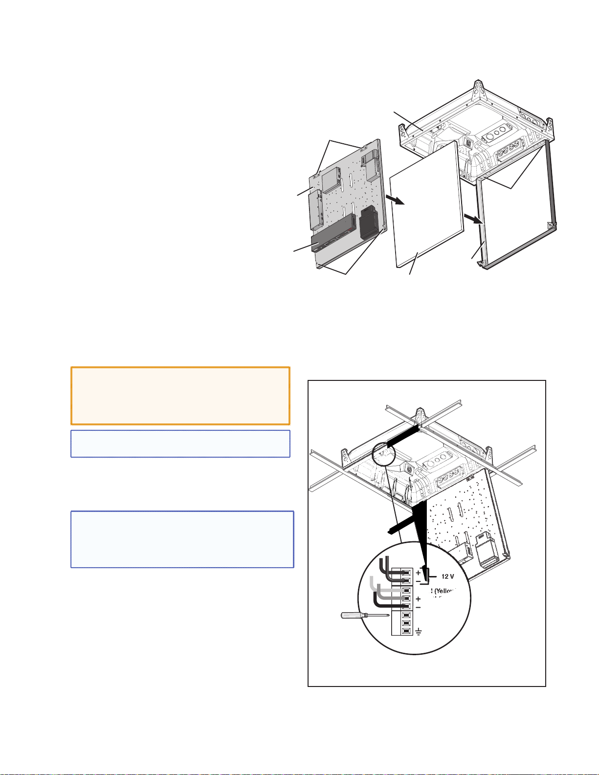
Device Mounting
Plate (with devices
installed)
D8. Install the Device Mounting Plate onto the Access Door.
To fit the mounting plate and devices on the
access door:
a. Align and slide the device mounting plate onto
the two hinge pins located at the top of the
door frame.
b. Secure the plate into place with
the two mounting plate screws,
located at the bottom of the
door frame.
D9. Cable the Switcher.
a. Connect the cables to the switcher as shown
on pages 43.
CAUTION: The signal transmission method is
specific for PVS 405D switcher working with PVT
digital wallplates. DO NOT connect the input
ports to an MTP, DTP, or XTP system or to an LAN
or data transmission system.
PoleVault
Switcher
(front panel
facing down)
PVM 220 Enclosure
Device Mounting
Plate Hinges
E
P
I
CHER
T
5SA
I
0
W
4
S
S
ULT
V
A
P
V
E
L
O
P
G
R
O
T
S
AGIN
P
S
EN
ITY
S
IV
JU
IT
NS
E
AD
S
EL
K
L
A
A
V
E
P
RM
E
AL
L
NO
N
G
I
S
O
T
F
I
UDI
L
E
A
C
VOI
AL
RM
O
N
AK
E
NAL
P
G
I
S
T
U
INP
O
I
D
5
U
X
A
U
A
S
NPUT
I
3
4
1
2
ECT
L
SE
G
NFI
CO
R
Door Frame
Device Mounting
Plate Screws
Ceiling Tile
Insert
Install the Mounting Plate onto the Access Door.
Device Mounting
Plate Hinge Pins
NOTE: For cable connections to optional devices see
the relevant device guide or manual.
b. Plug in the fan controller cable to the switcher
power supply. The fan comes already pre-wired
to the controller in the enclosure.
NOTE: The fan is controlled automatically by the
internal temperature of the PVM 220. The fan can
also be turned on or off manually (see below for
wiring). Manually controlling the fan overrides the
automatic thermal control mode.
The fan can be wired to a control system for manual
On/Off as follows (see figure at right for connectors):
• For manual On, wire a latching relay to the On
and Ground connectors on the fan controller.
• For manual Off, wire a latching relay to the Off
and Ground connectors on the fan controller.
c. Connect and dress the other device cables as
needed, providing enough slack to open and
close the access door.
12 V
TACH (Yellow)
FAN (Red)
FAN (Black)
ON
OFF
GROUND
Wire the fan controller for manual on and off.
PoleVault Digital Systems • Installation — Stage 4 (PVM 220 and PVS 405D)58
Page 65

D10. Verify and Configure the Setup.
Turn on the power to all the devices. Verify and
configure the system.
See the PVS 405D User Guide, or PVS 305SA IP
User Guide available at www.extron.com for full
details.
D11. Attach the Door Tether to the Door.
The PVM 220 enclosure has a coiled door tether
installed on the right side of the enclosure (when
viewed from the front).
After the device mounting plate is installed, the
tether should be attached to the door to ensure
safety when the door is opened.
To attach the tether to the door:
a. With the door fully open, locate the
door tether attached within the
enclosure. The coiled tether has a looped end
to be attached to the door.
b. In the lower corners of the door locate the
cutout with a “T” shaped metal tab (see figure
at right).
c. Stretch the tether and close up the door until
the loop on the tether can be carefully slid over
the “T” tab on the door. Ensure the loop is
completely over the “T”.
d. Carefully lower the door to the full extent of the
tether to ensure it functions correctly.
Push the tether loop completely over the T tab on the door.
Attach the door tether.
D12. Secure the Door Latches.
Both door latches can be made secure so the door
cannot be opened accidentally or inadvertently.
To secure the latches close the door and tighten
down the small set screws onto the latch (see the
figure at right).
For full safety secure both latches.
PoleVault Digital Systems • Installation — Stage 4 (PVM 220 and PVS 405D) 59
To secure the latch from opening
tighten the set screw onto the latch.
Secure the door latch.
Page 66

PoleVault Digital Systems • Installation — Stage 4 (PVM 220 and PVS 405D)60
Page 67

Stage 5: Configuring the PVS 405D Switcher
Stage 5 Involves installing the programs shown below.
Items needed to help complete this stage:
• Laptop (or PC) with a network connection
• PCS (Product Configuration Software) program
by download from www.extron.com)
• Global configurator software
• MLC 104 IP Plus User Guide
• Projector manufacturer guide
• Device driver and driver package
(download from www.extron.com)
1. Configure the Switcher — PCS Product
Configuration Software Program
a. Download and install the Extron Product
Configuration Software (PCS) program onto the
PC that is to be connected to the PVS 405D.
b. Connect the switcher to the PC via the front
panel USB and ensure they are both powered
and connected to the LAN.
ü Select online device or emulation mode (below).
c. Click on the desktop PCS icon to launch
the PCS utility.
NOTE: If you have installed PCS version 2.x,
open the embedded PCS Help file and
follow the instructions to access and
configure your switcher.
d. Select Connect to Online Devices tab and
then the online connection format (USB). Click
Connect.
Alternatively select Start New Device File
tab, then scroll to the PVS 405D. Click Open
Device
e. Once the program is running click on the blue
icon in the top right corner. Select Help File
and follow the instructions.
. The window opens in emulation mode
NOTE: An offline emulation of the
PVS 405D can aid in becoming familiar
with the device before configuring an
active unit.
† Accessing the Help File in PCS.
PoleVault Digital Systems • Installation — Stage 5 (Configuration)
61
Page 68

2. Configure the System — Global Configurator.
a. Download and install the Extron Global
Configurator (GC) configuration program
(available at www.extron.com) on the PC.
b. Ensure the PC and the MLC 104 IP Plus are
connected to the LAN and powered on.
NOTE: Alternatively, connect a 2.5 mm TRS
configuration cable (part number
70-335-01) to the PC and to the front panel
configuration port of the
MLC 104 IP Plus.
c. Launch the Global Configurator program and
click on Help, Contents, or press <F1>.
Load Global Configurator software
Ç
Launch Global Configurator
d. Select the MLC 104 IP Plus/PoleVault
system from the drop-down box in tyhe Help
file. Follow the instructions on the Help page to
configure the MLC.
e. To move to the next page in the Help file (as
shown in the yellow box, figure 2e), click the NEXT
button above the drop-down box. Repeat as
needed, following the instructions on the pages
to configure the MLC 104 IP Plus.
î
Select MLC 104 IP Plus/PoleVault IP System
ï
Ú¶ Configure the MLC 104 IP Plus
PoleVault Digital Systems • Installation — Stage 5 (Configuration)62
Page 69

3. Test the System.
a. Connect all the input devices (PC, DVD,
document camera, and, where desired, LAN
cables, and so forth) to the transmitters and
power up the input devices. Check that power
and signal are present at the transmitters. The
LEDs light red when only power is present
and light green when power and a signal are
present.
b. At the MLC 104 IP Plus, turn on the Display.
Once the the projector is powered up, check
with an active video source (PC or DVD) that a
good image is shown on screen.
NOTE: If the display does not turn on,
check the MLC controller configuration
and wiring.
c. Properly align and adjust projector mounting
settings as follows:
• Adjust the rotation (yaw) by turning the unit
on the projector pole. Secure the location by
tightening the two set screws on the UPB
mount plate to the pole (see below right).
• Loosen all pivot screws and adjust the vertical
angle (pitch) of the projector. Lock down the
four adjustment screws.
• Adjust the horizontal tilt (roll) of the projector.
Lock down all the remaining adjustment and
pivot screws.
• Adjust the image settings on the projector
(zoom, focus, keystone, brightness, contrast,
and so on). See the projector user manual.
Connect and turn on the input devices,
Ö
and turn on the display at the MLC.
Pitch/Vertical Angle
Yaw/Rotation
Roll/Tilt
ñ Check that an image is present, and
adjust as needed.
Vertical
Angle Adjustment
and Pivot
Point Screws
PoleVault Digital Systems • Installation — Stage 5 (Configuration) 63
Horizontal Angle
Adjustment and
Pivot Point Screws
Tighten these 2 set screws
(one each side) to lock the
UPB onto the pole.
Adjuster
Plate Locking Screws (4)
Page 70

d. Test the controller configuration as follows:
)
• Check that the MLC is controlling the projector
and PVS 405D switcher, and outputs the
correct image when switching inputs.
• Check the projector power control (turn it off
and on at the MLC).
• Adjust the configuration as necessary.
e. Adjust the audio input sensitivity as follows:
• Ensure there is an audio source at each
transmitter.
• On the PVS switcher, set the volume for each
input by selecting an input and rotating the
Volume encoder to a comfortable maximum
level, where the input “normal” LED is lit,
indicating the level is set properly. This ensures
Test the MLC configuration is correct.
õ
there is no clipping if the MLC volume is turned
to maximum during operation.
• Repeat step e for all inputs.
f. Where installed, to adjust the microphone
sensitivity switch on the microphone, press and
hold the volume down button until no beeps
are heard from the speakers. Then press and
hold the volume up button until six beeps are
heard. To adjust the VoiceLift audio output level
rotate the VoiceLift encoder on the switcher to
the “normal” setting and the LED lights. Test
and adjust the microphone so that the amplified
voice is heard just above the normal voice level
at each speaker location. See the VoiceLift User
Guide, and page 66 of this guide for details.
NOTES:
• The MLC volume control does not control
the VoiceLift volume.
• By default the switcher has been configured
so that input level and VoiceLift input
adjustments may not be required.
INPUT
AUDIO LEVEL ADJUST
PEAK
VOICELIFT
NORMAL
SIGNAL
PEAK
NORMAL
SIGNAL
PAGING
PEAK
SENSOR
NORMAL
SIGNAL
SENSITIVITY
Level set too high,
lower input gain
Level has been
properly adjusted
Signal threshold
-20 dBV (-18 dBu
PVS 405D
POLEVAULT SWITCHER
® Adjust the audio levels on the PVS 405D.
PoleVault Digital Systems • Installation — Stage 5 (Configuration)64
Page 71

g. Where installed, it may be necessary to adjust
the sensitivity of the Priority Paging system.
During a test transmission of the paging system
rotate the Paging Sensor encoder until program
audio is no longer heard from the PoleVault
speakers. See the Priority Page Sensor
Installation Instructions, or page 67 of this
guide, for full details.
NOTE: The Paging Sensor feature must be
enabled using the MLS Configuration software
or SIS commands prior to adjustment.
4. Final Installation.
a. Slide the covers of the PMK onto the base
plate, ensuring the power cable can exit the unit
through the power cable access slot.
b. Using a 5/32 inch hex wrench, tighten down the
four screws on the PMK to secure the sides in
place.
c. Check and tighten the adjuster plate locking
screws on the projector bracket.
d. Hole plugs can be used to cover any exposed
holes in the slotted pipe if necessary.
Ü Slide the covers onto the PMK 560.
PoleVault Digital Systems • Installation — Stage 5 (Configuration) 65
Page 72

T
Loc
Optional Accessory Installation — VoiceLift System
LR
8
AMPLIFIED AUDIO OUT
REMOTE
LAN 1 LAN 2 LAN 3
RS-232
G
G
SOR
AUX
OT
D
T
S
AMPLIFIED AUDIO
O
O
TE
-232
The Extron VoiceLift system is an easy-to-use, low-power, voice amplification system that ensures the speaker’s
voice can be clearly heard at a comfortable level throughout the classroom. Speech is picked up by the pendant
microphone worn by the teacher and is transmitted via wireless from a base station receiver and the PVS 405D
to the installed ceiling speakers.
For detailed installation information, see the
VoiceLift Installation Instructions, supplied
with the device.
VoiceLift System Included Parts:
• VLP 202 Pendant Microphone
• VLR 102 Receiver
• Wall charger
Installation Procedure
1. Determine the optimal receiver location and
mark and drill a 2.5 inch diameter hole in the
ceiling tile where it is to be installed.
2. Insert the ceiling bracket screw through the
back plate (attached to the housing) and the
hole in the ceiling tile and loosely attach the Z
bracket.
3. Align the back plate knockout over the hole in
the ceiling tile and tighten the bracket screw to
secure.
4. Replace the ceiling tile.
5. Pull the communication and power RJ-45
Ethernet cable (and other secondary use
cables) through the receiver base and connect
the Ethernet cable to the Receiver Out port
(the RJ-45 connector on the left on the receiver
base).
6. If desired, set the Tone switch on the receiver
base. Set the Mix DIP switch on the receiver to
Off as the Aux In port (on the VLR) is not used.
7. Place the dome onto the housing, align the
arrows on the dome locking tab and on the
housing rim. Turn the dome until it locks in place
(approximately 1/8 turn).
8. Pull the cables from the receiver to the PVS
405D switcher location, through the pipe and
down into the PMK 560.
9. Disconnect the power from the switcher, and
plug the included VoiceLift RJ-45 into the PVS
405D VoiceLift receiver port.
10. Replace power to the switcher. This also
powers the VoiceLift receiver.
b Attach the Z bracket to the ceiling tile
and the back plate.
wist to
k
Tab
Align Arrows
Tab
Arrow
Receiver
Dome
Arrow
Dot
g Align the arrows on the housing rim and
the dome tab.
OUTPUT AUDIO OUT
TPUTAUDIO OUT
L
R
HDMI
INPUT 5
5
R
Plug VoiceLift cable into PVS 405D.
i
PVS 405D
PAGING
AGIN
EN
SENSOR
VOICELIFT
+V
AUX OVER PVT
VoiceLift Input
DO NOT
N
GROUN
GROUND
R SHOR
OR SHORT
PEAKER
SPEAKER
UTPUT
OUTPUTS
VER PVT REM
IR
Tx Rx
SG
T
4/
Ω
Ω
PoleVault Digital Systems • Optional Accessories66
Page 73

Optional Accessory Installation — Priority Page Sensor (PPS 35)
S
35
ClassroomAdmin Building
Ceiling Mounted
To Classroom
Paging Speakers
Paging Speaker
Sensor
Output
PPS 35
PP
Priority Page Sensor
riority Page Sensor
(installed on Speaker
(installed on Speaker
Front Grille)
Plenum cable
Typical PPS 35 paging system with PVS 405D switcher.
The Extron PPS 35 Priority Page Sensor works with
the PVS 405D PoleVault Digital Switcher only and is
an optional part of a PoleVault, a PlenumVault, or a
WallVault system.
For detailed information, see the Priority Page
Sensor Kit Installation Instructions, supplied with the
device.
The PPS 35 mounts to the front face of any public
address (PA) loudspeakers with the pre-installed
hook-and-loop fastener. The cable is connected to
the rear panel 3-pole captive screw Paging Sensor
port of the PVS 405D switcher, located up to
50 feet away. Fifteen feet of cabling is supplied
already attached to the sensor.
When the Priority Page Sensor senses a PA system
broadcast, it sends a signal to mute the audio
output of the switcher for the duration of the PA
broadcast.
AN 1 LAN 2 LAN 3
L
R
L
FIED AUDIO OUT
AMPLI
T
4/8
DO NO
Ω
GROUND
OR SHORT
SPEAKER
OUTPUTS
REMOTE
S-232
R
IR
OVER PVT
G
TxRx
SG
PVS 405SA IP
PAGING
SENSOR
VOICELIFT
R
AUDIO OUT
+V
L
OUTPUT
AUX
R
INPUT 5
DMI
INPUTS
H
L
3/4
INK
L
SIG
1/2
NK
LI
SIG
POWER
AX
12V
3A M
Paging
PVT IN
PVT IN
Sensor
Input
Extron
PVS 405D
PoleVault Switcher
Extron
FF 120
Flat Field Speakers
PPS 35 Prority Page Sensor (part number 70-1074-01)
NOTES:
• The PPS 35 unit is NOT plenum rated and
should not be installed above a drop ceiling.
• The cable attached to the PPS 35 unit IS plenum
rated and may be installed above a drop ceiling.
• The PPS 35 is NOT compatible with the PPC 25
Priority Page Controller.
PoleVault Digital Systems • Optional Accessories 67
Page 74

PVS 405D
A
T
5
g
5D
AUX
VOIC
T
Black (+)
J
Installation Procedure
1. Using the hook-and-loop fastener, attach the
PPS 35 to the front grille of a paging system
speaker that is located within fifty feet of the
PVS 405D.
2. Run the attached cable to the switcher location.
3. Connect the end of the three-wire cable to the
Paging Sensor port on the rear panel of the
PVS 405D. Wire the connector as shown at right.
4. Test and configure the PPS 35 using the
PVS 405D front panel, or using SIS commands, or
via the PCS configuration software.
Attach the Sensor to the front grille of a speaker
a
Paging Sensor Port
PVS 405D
PAGING
SENSOR
AUX
VS 40
VOICELIFT
+V
Red (+V)
Drain Wire (-)
ELIF
AUDIO OUT
UDIO OU
R
INPUT 5
R
Wire the sensor into the PVS 405D
c
PVS 405D
AUDIO LEVEL ADJUST
AUDIO LEVEL AD
PAGING
PEAK
NORMAL
NORMAL
SIGNAL
IGNAL
SENSOR
SENSITIVITY
T
Configure the PPS 35 via the front panel
d
POLEVAULT SWITCHER
PoleVault Digital Systems • Optional Accessories68
Page 75

Optional Accessory Installation — Priority Page Sensor Kit (PPS 25)
Admin Building
To Classroom
Paging Speakers
Classroom
Ceiling Mounted
Paging Speaker
Priority
Page
Sensor
Sensor
Output
Paging System
Typical PPS 25 paging system with PVS 405D switcher.
The Priority Page Sensor Kit momentarily silences
classroom audio whenever a page is made from a
public address (PA) system.
For detailed information, see the Priority Page
Sensor Kit Installation Instructions, supplied with the
device.
PVS 405SA IP
PAGING
SENSOR
VOICELIFT
R
AUDIO OUT
+V
L
OUTPUT
AUX
R
INPUT 5
DMI
INPUTS
H
L
3/4
INK
SIG L
1/2
IG LINK
S
POWER
AX
12V
PVT IN
3A M
Paging
PVT IN
Sensor
Input
Extron
PVS 405D
PoleVault Switcher
OVER PVT
AMPLIFIED AUDIO OUT
DO NO
GROUND
OR SHORT
SPE
OUTPUTS
IR
S G G
FF 120
Flat Field
Speakers
LAN 2 LAN 3
AN 1
L
L R
T
4/8
Ω
AKER
REMOTE
RS-232
TxRx
NOTE: The Priority Page Sensor works with
traditional 25 V or 70 V and 4/8 ohm PA
systems. It is not designed for, and may not
work properly with, two-way intercoms or
systems that are IP-based or that use digital
clocks.
Priority Page Sensor Kit Included Parts:
• Priority Page Sensor (part number 70-619-01)
• UL Listed junction box with a cable clamp and
a lid
• 35 feet (10.7 m) of sensor cable
PoleVault Digital Systems • Optional Accessories 69
Page 76
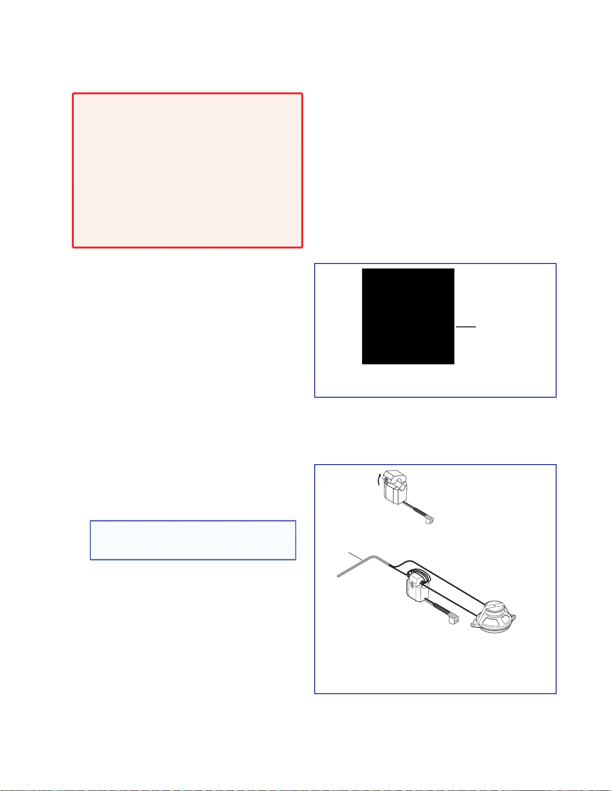
Installation Procedure
Ceiling Mounted
Paging Speaker
Priority
Page
Sensor
Strip plenum jacket from
speaker cable to reveal
two speaker wires.
Speaker Cable with
Plenum Jacket Intact
WARNING: Risk of serious personal injury
if installation is not done correctly. All
structural steps, anchoring, and electrical
installation should be performed by qualified
personnel in accordance with local and national
building codes, fire and safety codes, and/or
local and national electrical codes.
To meet the plenum rating requirement,
the Priority Page Sensor assembly must be
installed in a UL Listed junction box with
a cover. All cables to and from the sensor
must be plenum rated.
1. Choose a suitable location for the sensor near,
and in series with, the speakers.
2. If the sensor is to be located in a plenum
space, the junction box (provided) can be
used. Knock out an opening at one end of the
box and attach the cable clamp (see figure at
Cable Clamp
right). Secure the box at the sensor location.
3. Disconnect the PA system speaker cable.
Remove the outer protective jacket from the
speaker cable to expose the two speaker wires
from the sensor to the speaker (as shown at lower
UL-Compliant Junction Box and Cover
b
right). Do not remove the inner protective jackets
that cover the individual wires.
If the sensor is to be located in a plenum space,
feed a loop of one of the exposed speaker wires
through the cable clamp into the junction box.
The other wire must bypass the sensor to be
connected later directly to the speaker.
4. Open the top of the Priority Page Sensor and loop
the speaker wire that is inside the junction box
Open the
Page Sensor
tightly around the top part of the sensor.
NOTE: Loop only one of the speaker wires
around the sensor cover. Do not loop both
wires. Polarity need not be observed.
The other speaker wire must bypass the sensor
and connect directly to the speaker.
• For a 25 V or 70 V system, wrap 5 to 8 loops.
• For a 4/8 ohm system, wrap 2 to 4 loops.
5. Close and latch the top of the Priority Page
Sensor. Reconnect the speaker cable to the
speaker.
PoleVault Digital Systems • Optional Accessories70
Open the sensor and loop a wire around the
d
sensor.
Page 77

6. Strip 3/16 inches of insulation from each
AUDIO OUT
5
5D
AUX
VOIC
conductor on the bare wire end of the remaining
blue sensor cable. Do not tin the leads. Feed
the wire into the junction box (clamping it down
if necessary) and connect the wires to the Page
Sensor port captive screw connector (use the +
and - poles) on the rear panel of the PVS 405D.
Polarity need not be observed.
7. If a junction box is being used in a plenum space,
ensure the sensor and all wires fit inside the box
(as shown at right). All cables leaving the box must
be plenum rated. Tighten the cable clamp and
secure the lid to the junction box.
NOTE: To enable the switcher’s paging sensor
port, use the PCS Configuration program,
available at
www.extron.com.
PVS 405D Paging Sensor Port
PVS 405D
AUX
+V
PVS 40
VOICELIFT
ELIFT
AUDIO OUT
INPUT 5
R
R
PAGING
SENSOR
Page Sensor
Wire the Priority Page Sensor to the Paging
f
Sensor port on the switcher.
Ensure the sensor and wires fit completely
g
inside the junction box before attaching the
cover.
PoleVault Digital Systems • Optional Accessories 71
Page 78

Testing and Adjustment Procedure
J
VOIC
To test that the classroom audio is muted when a
PA system announcement (a page) occurs:
1. Turn the classroom audio on.
2. Speak into the PA system microphone. The
classroom audio should be muted while the PA
page occurs and be restored when the page
ends.
3. If the program fails to mute the classroom audio
during a page, turn the Sensitivity adjustment, on
the front panel of the PVS 405D, clockwise.
4. If the classroom audio is muted without a page
occurring, turn the Sensitivity adjustment
counterclockwise.
PVS 405D
AUDIO LEVEL ADJUST
AUDIO LEVEL AD
VOICELIFT
c
PEAK
ELIFT
NORMAL
NORMAL
SIGNAL
IGNAL
and d Sensitivity Adjustment Encoder
PAGING
SENSOR
SENSITIVITY
POLEVAULT SWITCHER
PoleVault Digital Systems • Optional Accessories72
Page 79

Outline of Installation Steps for WallVault Digital Systems (WMK 160)
Stage 1 — Install the Screen and Projector.
c Mark the screen location (page 18).
c Install projector to verify location (page 18).
c Verify the image location (page 21).
c Cut the ceiling tile (page 22).
c Preliminary safety hardware installation (page 22).
c Finish projector drop ceiling mount installation (page 23).
c Secure the projector drop ceiling mount to the ceiling (page 24).
c Install the electrical box (if required) (page 25).
c Install the screen (page 25).
Stage 2 — Mount the PVT Wall Plates and the MLC 104 IP Plus.
Install the mud rings (page 29).
c
c Pull cables (at the input locations) (page 30).
c Install the wall plates (page 31).
c Install the MediaLink Controller (page 32).
Stage 3 — Install the FF 120 Speakers.
c Cut the ceiling tile (page 36).
c Install the speaker on the drop ceiling (page 36).
c Terminate the speaker cable for the PVS switcher (page 38).
Stage 4B — Install the WMK 160 and PVS 405D.
c Install the WMK 160 base plate (page 44).
c Install the switcher onto the base plate (page 45).
c Run the cables to the WMK 160 location (page 46).
c Cable the switcher (page 46)
Stage 5 — Configure the PoleVault Switcher and the System.
c Configure the switcher — PCS Configuration program (page 61).
c Configure the system — Global Configurator (page 62).
c Test the system (page 63).
c Final installation (page 65).
Optional Accessory Installation
c
VoiceLift System (page 66).
c Priority Page Sensor PPS 35 (page 67).
c Priority Page Sensor Kit PPS 25 (page 69).
The pages listed above contain instructions for installing the WallVault Digital System. Where possible, line
drawings and photos from an actual installation are used to clarify some of the steps discussed in the text. Most
images have a number corresponding to the step that is being described (for example, Ñ).
PoleVault Digital Systems • Installation Overview 73
Page 80

Outline of Installation Steps for WallVault Digital Systems (USFM 100)
Stage 1 — Install the Screen and Projector.
c Mark the screen location (page 18).
c Install projector to verify location (page 18).
c Verify the image location (page 21).
c Cut the ceiling tile (page 22).
c Preliminary safety hardware installation (page 22).
c Finish projector drop ceiling mount installation (page 23).
c Secure the projector drop ceiling mount to the ceiling (page 24).
c Install the electrical box (if required) (page 25).
c Install the screen (page 25).
Stage 2 — Mount the PVT Wall Plates and the MLC 104 IP Plus.
Install the mud rings (page 29).
c
c Pull cables (at the input locations) (page 30).
c Install the wall plates (page 31).
c Install the MediaLink Controller (page 32).
Stage 3 — Install the FF 120 Speakers.
c Cut the ceiling tile (page 36).
c Install the speaker on the drop ceiling (page 36).
c Terminate the speaker cable for the PVS switcher (page 38).
Stage 4C — Install the USFM 100 and PVS 405D.
c Install the USFM 100 base plate (page 48).
c Install the switcher onto the base plate (page 48).
Stage 5 — Configure the PoleVault Switcher and the System.
Optional Accessory Installation
The pages listed above contain instructions for installing the WallVault Digital System. Where possible, line
drawings and photos from an actual installation are used to clarify some of the steps discussed in the text. Most
images have a number corresponding to the step that is being described (for example, Ñ).
c Run the cables to the USFM 100 location (page 49).
c Cable the switcher (page 50)
c Attach the boom arm, power supply, and projector (page 50)
c Configure the switcher — PCS Configuration program (page 61).
c Configure the system — Global Configurator (page 62).
c Test the system (page 63).
c Final installation (page 65).
c VoiceLift System (page 66).
c Priority Page Sensor PPS 35 (page 67).
c Priority Page Sensor Kit PPS 25 (page 69).
PoleVault Digital Systems • Installation Overview74
Page 81

Outline of Installation Steps for PlenumVault Digital Systems (PVM 220)
Stage 1 — Install the Screen and Projector.
c Mark the screen location (page 18).
c Install projector to verify location (page 18).
c Verify the image location (page 21).
c Cut the ceiling tile (page 22).
c Preliminary safety hardware installation (page 22).
c Finish projector drop ceiling mount installation (page 23).
c Secure the projector drop ceiling mount to the ceiling (page 24).
c Install the electrical box (if required) (page 25).
c Install the screen (page 25).
Stage 2 — Mount the PVT Wall Plates and the MLC 104 IP Plus.
Install the mud rings (page 29).
c
c Pull cables (at the input locations) (page 30).
c Install the wall plates (page 31).
c Install the MediaLink Controller (page 32).
Stage 3 — Install the FF 120 Speakers.
c Cut the ceiling tile (page 36).
c Install the speaker on the drop ceiling (page 36).
c Terminate the speaker cable for the PVS switcher (page 38).
Stage 4D — Install the PVM 220 and PVS 405D.
c Remove the device mounting plate from the access door (page 53).
c Remove ceiling tile and install suspension cables (page 53).
c Suspend the main PVM 220 enclosure from the ceiling (page 54).
c Run AC power wiring to the AC module in the PVM 220 (page 55).
c Run signal and control cables to the PVM 220 (page 56).
c Install devices onto the device mounting plate (page 57).
c Cut and install ceiling tile into the access door (page 57).
c Install the mounting plate onto the access door (page 58).
c Cable the switcher (page 58).
c Verify and configure the setup (page 59).
c
Attach the door tether to the door (page 59).
c Secure the door latches (page 59).
Stage 5 — Configure the PoleVault Switcher and the System.
c Configure the switcher — PCS Configuration program (page 61).
c Configure the system — Global Configurator (page 62).
c Test the system (page 63).
c Final installation (page 65).
PoleVault Digital Systems • Installation Overview 75
Page 82

Optional Accessory Installation
c VoiceLift System (page 66).
c Priority Page Sensor PPS 35 (page 67).
c Priority Page Sensor Kit PPS 25 (page 69).
The pages listed above contain instructions for installing the PlenumVault Digital System. Where possible, line drawings
and photos from an actual installation are used to clarify some of the steps discussed in the text. Most images have a
number corresponding to the step that is being described (for example, Ñ).
PoleVault Digital Systems • Installation Overview76
Page 83

Extron Warranty
Extron Electronics warrants this product against defects in materials and workmanship for a period of three years
from the date of purchase. In the event of malfunction during the warranty period attributable directly to faulty
workmanship and/or materials, Extron Electronics will, at its option, repair or replace said products or components,
to whatever extent it shall deem necessary to restore said product to proper operating condition, provided that it is
returned within the warranty period, with proof of purchase and description of malfunction to:
USA, Canada, South America,
and Central America:
Extron Electronics
1230 South Lewis Street
Anaheim, CA 92805
U.S.A.
Europe and Africa:
Extron Europe
Hanzeboulevard 10
3825 PH Amersfoort
The Netherlands
Asia:
Extron Asia Pty Ltd
135 Joo Seng Road, #04-01
PM Industrial Bldg.
Singapore 368363
Singapore
This Limited Warranty does not apply if the fault has been caused by misuse, improper handling care, electrical
or mechanical abuse, abnormal operating conditions, or if modifications were made to the product that were not
authorized by Extron.
NOTE: If a product is defective, please call Extron and ask for an Application Engineer to receive an RA (Return
Authorization) number. This will begin the repair process.
Japan:
Extron Electronics, Japan
Kyodo Building, 16 Ichibancho
Chiyoda-ku, Tokyo 102-0082
Japan
China:
Extron China
686 Ronghua Road
Songjiang District
Shanghai 201611
China
Middle East:
Extron Middle East
Dubai Airport Free Zone
F12, PO Box 293666
United Arab Emirates, Dubai
USA: 714.491.1500 or 800.633.9876 Europe: 31.33.453.4040
Asia: 65.6383.4400 Japan: 81.3.3511.7655
Units must be returned insured, with shipping charges prepaid. If not insured, you assume the risk of loss or damage
during shipment. Returned units must include the serial number and a description of the problem, as well as the
name of the person to contact in case there are any questions.
Extron Electronics makes no further warranties either expressed or implied with respect to the product and its quality,
performance, merchantability, or fitness for any particular use. In no event will Extron Electronics be liable for direct,
indirect, or consequential damages resulting from any defect in this product even if Extron Electronics has been
advised of such damage.
Please note that laws vary from state to state and country to country, and that some provisions of this warranty may
not apply to you.
77
Page 84

Outline of Installation Steps for PoleVault Digital Systems
Stage 1 — Install the Screen and Projector.
c Mark the screen location (page 18).
c Install projector to verify location (page 18).
c Verify the image location (page 21).
c Cut the ceiling tile (page 22).
c Preliminary safety hardware installation (page 22).
c Finish projector drop ceiling mount installation (page 23).
c Secure the projector drop ceiling mount to the ceiling (page 24).
c Install the electrical box (if required) (page 25).
c Install the screen (page 25).
Stage 2 — Mount the PVT Wall Plates and the MLC 104 IP Plus.
Install the mud rings (page 29).
c
c Pull cables (at the input locations) (page 30).
c Install the wall plates (page 31).
c Install the MediaLink Controller (page 32).
Stage 3 — Install the FF 120 Speakers.
Cut the ceiling tile (page 36).
c
c Install the speaker on the drop ceiling (page 36).
c Terminate the speaker cable for the PVS switcher (page 38).
Stage 4A — Install the PMK 560 and PVS 405D.
Install the PMK 560 base plate (page 40).
c
c Pull the cables (at the switcher location) (page 41).
c Finish installing the pole mount kit (page 43)
Stage 5 — Configure the PoleVault Switcher and the System.
Configure the switcher — PCS Configuration program (page 61).
c
c Configure the system — Global Configurator (page 62).
c Test the system (page 63).
c Final installation (page 65).
Optional Accessory Installation
VoiceLift System (page 66).
c
c Priority Page Sensor PPS 35 (page 67).
c
Priority Page Sensor Kit PPS 25 (page 69).
The pages listed above contain instructions for installing the PoleVault Digital System. Where possible, line drawings and
photos from an actual installation are used to clarify some of the steps discussed in the text. Most images have a number
corresponding to the step that is being described (for example,
Ñ).
NOTE: Similar outline lists of steps for installing WallVault (WMK 160 or USFM 100) and PlenumVault (PVM 220)
Digital Systems can be found on pages 73 through 76.
Extron Headquarters
+1.800.633.9876 (Inside USA/Canada Only)
Extron USA - West Extron USA - East
+1.714.491.1500 +1.919.850.1000
+1.714.491.1517 FAX +1.919.850.1001 FAX
Extron Europe
+800.3987.6673
(Inside Europe Only)
+31.33.453.4040
+31.33.453.4050 FAX
© 2014 Extron Electronics All rights reserved. www.extron.com
Extron Asia
+65.6383.4400
+65.6383.4664 FAX
Extron Japan
+81.3.3511.7655
+81.3.3511.7656 FAX
Extron China
+86.21.3760.1568
+86.21.3760.1566 FAX
Extron Middle East
+971.4.299.1800
+971.4.299.1880 FAX
Extron Korea
+82.2.3444.1571
+82.2.3444.1575 FAX
Extron India
1800.3070.3777
(Inside India Only)
+91.80.3055.3777
+91.80.3055.3737 FAX
 Loading...