

Page 1
PCM 340 • Installation Guide
T-frame
X"
Y"
Minimum and
Maximum
Throw Distance Marks
Projector
Front
IMPORTANT SAFETY INSTRUCTIONS
When using this accessory, basic precautions should always be followed, including the following:
WARNING: Risk of Personal Injury. Maximum setup load for the PCM is 50 lbs (22.7 kg).
SAVE THESE INSTRUCTIONS
NOTE: Refer to local building standards and codes to verify that the installation will meet the regulatory requirements.
Observe all local and national building and safety codes, UL requirements, and ADA accessibility guidelines.
WARNING: Risk of Personal Injury and property damage. Do not exceed specified weight limits of any component of
the installation. Follow the manufacturer's specifications and installation instructions.
Read all instructions before starting installation.
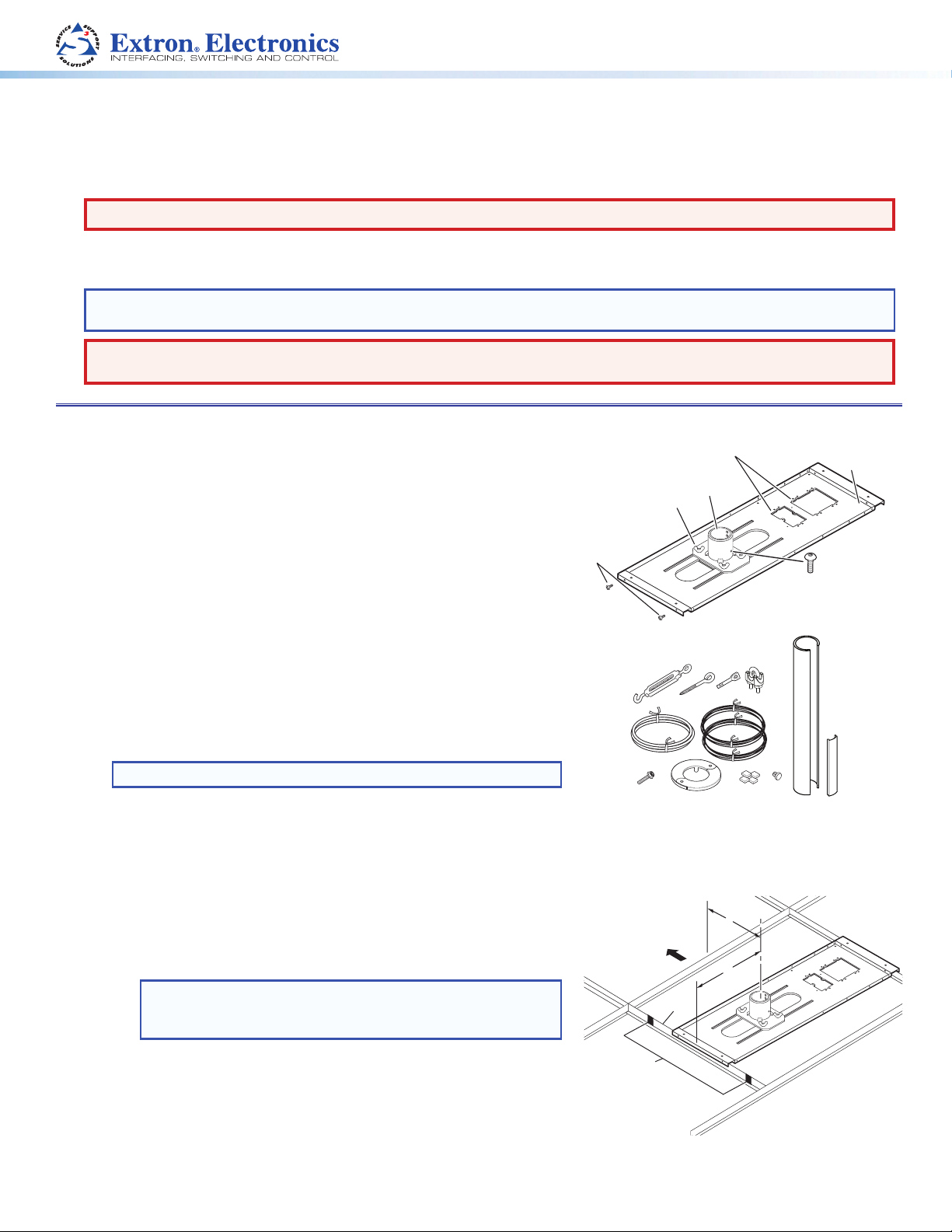
The Extron PCM 340 Drop Ceiling Projector Mount is used for hanging
PoleVault® System AV products and various projectors.
The PCM is installed above the drop ceiling and secures the adjustable
pipe in a pass-through pipe adapter plate. The pipe then supports the
mounting of the Extron PMK 550 and UPB 25 projector bracket.
The key components of the PCM 340 are shown in figure 1.
Also included in the kit are:
4 turnbuckles, 5 lag eye bolts, 5 concrete anchors, 2 cable clamps,
1 safety wire – 15 feet, 2 tie wires – 30 feet, 4 T-frame screws, 2 set
screws,1 location screw, 4 adhesive pads, 11 hole plugs, 1 escutcheon
ring, (1) 25 inch slotted projector pipe with 1 snap-in trim piece.
1-gang and 2-gang Accessory Mounting
Points (for Power Sockets, for example)
Pipe
Adapter
Pipe Adapter Plate
Wing Nuts (4)
T-frame
Securing
Screws (4)
Base
Plate
Pipe Adapter
Set Screws (2)
Pre-Installation
Determine the exact location of the installation on the drop ceiling.
Consider the following:
• The vertical and horizontal offsets of the projector from the proposed
• The projector dimensions relative to the image target.
Installation
location.
NOTE: See the projector manual for details.
Step 1 — Mark the Frame and Cut the Ceiling Tile.
a. At the location for the projector, identify the ceiling tile and T-frame
where the PCM will be installed.
b. Remove the predetermined ceiling tile and mark the maximum and
minimum throw distances of the projector on the T-frame (see
figure 2).
TIP: Mark the screen direction on the back of the tile to
help with orientation of the tile when replacing it after
cutting�
If it helps, create more working space by removing the adjacent
tiles.
c. Place the PCM base plate over the T-frame, between the two marks.
Lightly tighten the T-frame securing screws (which can be inserted
on the inside or outside of the PCM).
d. Mark the location of the PCM base plate on the T-frame to aid in
replacing it in the correct location.
Figure 1. PCM 340 Parts
Figure 2. Minimum and Maximum
Throw Distances
1
Page 2
PCM 340 • Installation Guide (Continued)
e. Measure the distances X and Y (see figure 2) from the inner vertical
section of the front and left T-frame runners to the center of the Pipe
Adapter Plate.
f. Using these dimensions, mark and cut a hole (using a 2 inch
hole saw) for the projector pipe in the removed ceiling tile (see figure 3).
g. If required, to prepare the ceiling tile for a power outlet, use the PCM
plate to trace and cut out the 2-gang hole in the ceiling tile for a
UL approved RACO® junction box.
If this is not required, proceed to step 3.
TIP: Install any optional power outlets in the 2-gang opening on the
mounting plate, towards the outside edge of the mount, so
they do not interfere with the PMK 550 when installed.
Step 2 — Install the Electrical Box.
The following method is recommended for integrating a 4S RACO electrical
box (not supplied) on the PCM base plate (such as a RACO 231, 2 1/8 inch
deep, 4 x 4 inch electrical box and a RACO 778, 1/2 inch raised, 4 x 4 inch
plaster ring.
Install the RACO box on the PCM plate as follows:
a. Attach the box to the plate, using the smallest notches in opposite
corners of the cut-out (see figure 4). Do not tighten the screws fully
at this time.
b. On the room side of the tile, slide the plaster ring under the screws.
c. Fully tighten the screws
Top Side
Underside
Figure 3. Mark and start cutting on
underside. Finish on top
side.
Raco 231
Use the smallest
notches when
attaching the
Raco box.
WARNING: Risk of Personal Injury. For safety, complete all wiring
of the electrical boxes and accessories after the plate
is installed and secure.
All electrical installation should be done by a qualified
electrician.
NOTE: If installing a single-gang electrical box, use a Raco 503
junction box�
Step 3 — Secure the PCM Base Plate to the Ceiling.
Tie wire installation
a. Replace the cut ceiling tile, and temporarily replace the PCM base plate
over the ceiling tile.
b. Check the orientation and tile hole alignment hole(s) with the PCM
adapter plate by pushing the slotted pipe up through the hole into the
adapter plate.
c. When adequately satisfied the plate and hole align, remove the pipe.
d. Attach the four turnbuckles to the mounting plate, one at each corner.
ATTENTION: Risk of Personal Injury and property damage.
• DO NOT rest or lean on the mounting plate or
suspended ceiling when attaching the turnbuckles
and tie wire, or when drilling into the ceiling.
• For safest installation, insert the turnbuckle from
the outside so that it hooks inwards.
e. Mark and drill four holes, approximately 1¼ inch (32 mm) deep into
the ceiling joists, using a 1/4 inch (6.4 mm) diameter drill bit. Do this at
10 degrees out from vertical. Drill a fifth hole centered above the PCM
for the safety cable (see figure 5). The minimum joist size used should
be 2 inches by 4 inches.
Figure 4. Install RACO Box and
Plaster Ring.
Attach safety cable
to center holes and
secure with cable
10
clamps.
o
Attach tie wire
to the turnbuckles
and eye bolts.
Drill holes and
attach tie wires
10° out from
vertical.
Figure 5. Attach Tie Wire and Safety
Cable.
Raco 778
2
Page 3

f. Install appropriate anchors or lag eye bolts for the structural
ceiling into each drilled hole.
g. Loop the safety cable through the center anchor or lag eye bolt,
attach it to the plate center holes (figure 6) and secure it with the
cable clamps.
h. Cut appropriate lengths of the supplied tie wire.
Loop the wire through the anchors or lag eye bolts and the
turnbuckles, then twist the wire around itself at least five times.
i. Tighten the turnbuckles by hand (see figure 6), and level the plate
so that it just rests on the grid.
ATTENTION: Potential Damage to Property.
• The four hanging wires should be taut, taking
the full weight of the completed installation.
• Overtightening the turnbuckles could cause
the T-bar assembly to be lifted, making the
suspended ceiling bowed and unsafe.
j. Tighten the four T-frame securing screws on the PCM.
k. Push the slotted pipe up through the hole into the adapter plate
and tighten the location and set screws to secure the pipe in place.
Secure PCM to frame
(from either side)
PCM
Adjust the turnbuckles to take
up any slack in the hanging wire.
Figure 6. Adjust Turnbuckles.
T-frame
Step 4 — Final Installation.
a. Install the projector assembly and lock it into place.
b. Tuck the signal cables into the slotted pipe and firmly snap
the trim piece into place (see figure 7).
NOTE: The trim piece can be cut to the desired length.
c. Open the escutcheon ring and, with the tabs uppermost,fit the ring
around the slotted pipe (see figure 8), then close it. Slide the ring
up until it is snug against the ceiling tile.
d. Insert the hole plugs into the remaining open holes in the visible
part of the pipe.
e. Complete any further device installation according to the relevant
device manual.
Snap-in
Tr im Piece
Device Cables
Figure 7. Snap in Trim Piece.
Hole Plug
Escutcheon
Ring
Slotted
Projector Pipe
Figure 8. Fit Ring and Hole Plugs.
3
Page 4
PCM 340 • Installation Guide (Continued)
Specications
General
Maximum load capacity ������������������ 50 lbs (22�7 kg)
Material ����������������������������������������� Baseplate and pipe: aluminum,
Tie wire: steel, 14 AWG, 70,000 psi tensile strength
Dimensions
Base plate �������������������������������� 1�2" H x 26�4" W x 8�0" D (2�9 cm H x 67�0 cm W x 20�3 cm D)
Pipe ����������������������������������������� 25" length, 1�5"-11�5 NPT
Adjustment ranges ������������������������� 1�5" - 23�0" drop, 21�5", adjustable in 0�5" steps
NOTE: Drop distances are measured from the bottom of the hanger plate.
Product weight ������������������������������� 4�5 lbs (2 kg)
Shipping weight ����������������������������� 9 lbs (5 kg)
NOTE: Weights include the pipe.
Vibration ���������������������������������������� ISTA 1A in carton (International Safe Transit Association)
Regulatory compliance
Safety �������������������������������������� CE; c-UL, UL for use with UL Listed mount and projector; OSHPD anchorage pre-approval
Warranty ���������������������������������������� 3 years parts and labor
NOTE: Specifications are subject to change without notice.
26.39" (670.3 mm)
2X 1.00" (25.4)
8.00"
(203.2 mm)
2X 6.00"
(152.4)
Drop
2X 24.72" (627.8 mm)
23.71" (602.3 mm)
25.00"
(635.0 mm)
2.42"
(61.4)
1.15"
(29.2 mm)
THREADED HOLES APPEAR
ON THIS SIDE ONLY
2.00" (50.8 mm)
(TYP. SPACING)
Extron Headquarters
+1�800�633�9876 (Inside USA/Canada Only)
Extron Europe
+31�33�453�4040
© 2012 Extron Electronics — All rights reserved. All trademarks mentioned are the property of their respective owners. www.extron.com
4
(1 1/2"-11.5 NPT)
Extron Asia
+65�6383�4400
Extron Japan
+81�3�3511�7655
Extron China
+86�21�3760�1568)
Extron Middle East
+971�4�2991800
Extron Korea
+82�2�3444�1571
Extron India
+91�80�3055�3777
68-1573-01
Rev E
08 12
 Loading...