

Page 1
Setup Guide — P/2 DA8 and DA12 Series
(Continued on reverse side)
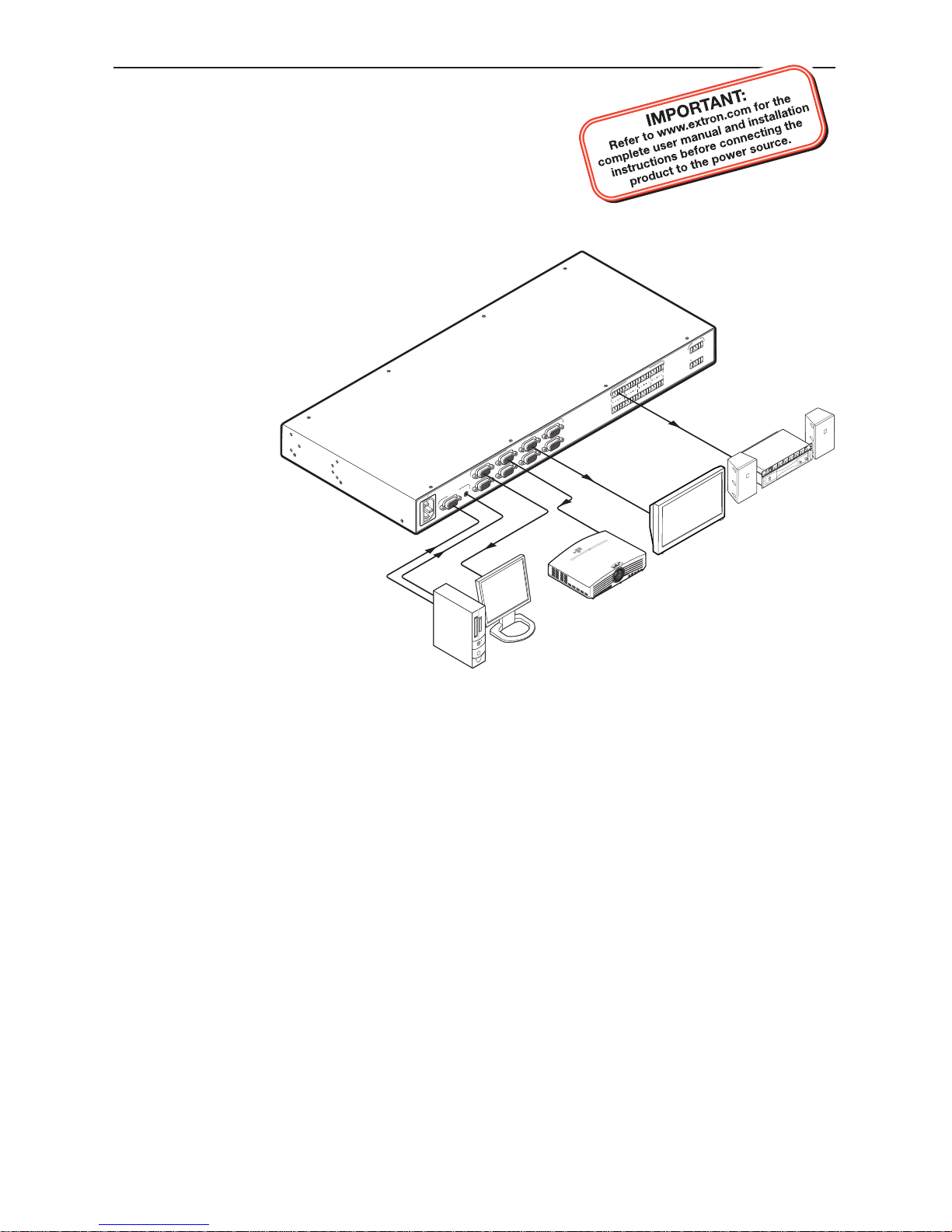
Installation
Step 1
Turn all the equipment off and disconnect all cables.
Step 2
Place the unit on a convenient table top or mount it in a rack, under a desk, or on a projector
mounting system. Follow the instructions included with the appropriate mounting kit.
Step 3
Use the provided IEC connector to connect the unit to a convenient power socket. The internal
power supply supports 100-240 VAC, 50-60 Hz.
C
Always use a power supply specified by Extron for this unit. Use of an unauthorized
power supply voids all regulatory compliance certification and may cause damage to the
supply and the distribution amplifier.
Step 4
Connect a video source to the video input, using a female DB-15 connector. Acceptable input
formats include: RGBHV, RGBS, RGsB, RsGsBs, YUV (tri-level and bi-level sync), S-video, and
composite video.
Step 5 (P/2 DA8 A and P/2 DA12 A models only)
Connect an unbalance audio source to the female 3.5 mm TRS connector.
Step 6
Connect up to eight (P/2 DA8 series) or twelve (P/2 DA12 series) display devices using female
DB-15 connectors. The output signal format follows that of the input.
N
Output 1 is used for DDC reference.
The Extron® P/2 DA8 and P/2 DA12 series of distribution
amplifiers distribute video (all models) and stereo audio
(P/2 DA8 A and P/2 DA12 A models only). Unless
otherwise stated, these instructions apply to all four
models.
W
These instructions provide a quick setup
guide for experienced installers. Installation
and service must be performed by authorized
personnel only.
100-240V
0.6
A
50-60Hz
INPUTS
VIDEO OU
TPUTS
P/2 D
A8 A
2 4
6 8
1 3 5
7
AUDIO OUTPUT
S
MUTE
L
R
7
L
R
8
L
R
5
L
R
6
L
R
3
L
R
4
L
R
1
L
R
2
1 3 5 7
2 4 6 8
A
PC
Local Monitor
Audio In
Video In
Projector
Plasma
Display
Sound
System
Page 2
Setup Guide — P/2 DA8 and P/2 DA12 Series (cont’d)
Extron USA - West
Headqu arters
+800 .633.987 6
Inside USA / Canada Only
+1.714.491.1500
+1.714.491.1517 FAX
Extron USA - East
+800 .633.987 6
Inside USA / Canada Only
+1.919.863.179 4
+1.919.863.179 7 FAX
Extron Europe
+800 .3987.6673
Inside Europe Only
+31.33. 453.404 0
+31.33. 453.405 0 FAX
Extron Asia
+800 .7339.876 6
Inside Asia Only
+65.6 383.44 00
+65.6 383.46 64 FAX
Extron Japan
+81.3.3 511.765 5
+81.3.3 511.765 6 FAX
Extron China
+400 .883.1568
Inside China Only
+86. 21.3760.1568
+86. 21.3760.1566 FA X
Extron Middle East
+971.4. 2991800
+971.4. 2991880 FA X
© 2010 Extron Electronics. All rights reserved.
68-1475-50
Rev. A
01 10
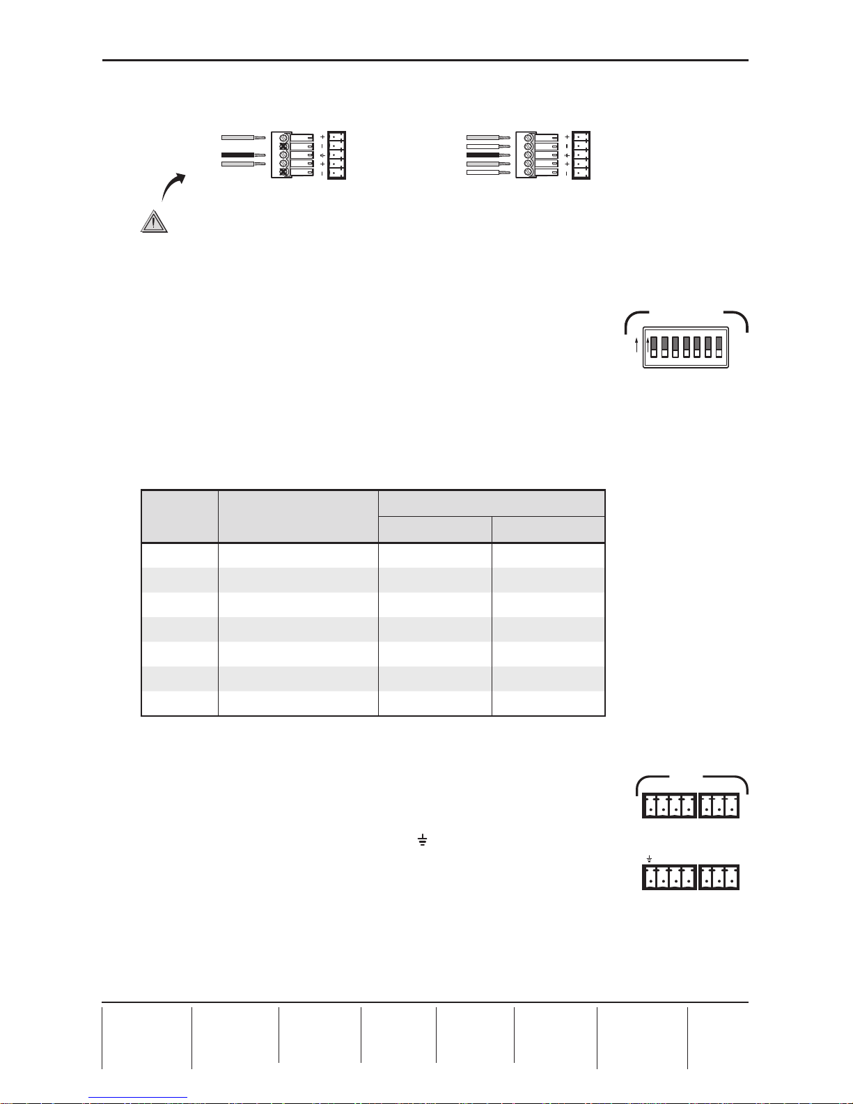
Step 7 (P/2 DA8 A and P/2 DA12 A models only)
Connect up to eight (P/2 DA8 A) or twelve (P/2 DA12 A) audio output devices to the 3.5 mm
5-pole captive screw connectors. Outputs can be balanced or unbalanced.
Unbalanced Stereo Output
Tip
NO GROUND HERE.
Sleeve(s)
Tip
NO GROUND HERE.
Balanced Stereo Output
Tip
Ring
Sleeve(s)
Tip
Ring
L R
L R
Left
Right
Left
Right
CAUTION
For unbalanced audio, connect the sleeve(s) to the center contact ground.
DO NOT connect the sleeve(s) to the negative (-) contacts.
Configuration
Sync impedance DIP switches
Set the front panel DIP switches to correct for sync impedance mismatches,
or to solve laptop compatibility issues on the video input or reflection
problems on the video output.
Switch 1 (sync input impedance) — The default setting is Off (510 ohms). If the image from
the laptop is unstable, slide DIP switch 1 to On (10k ohms).
Switches 2-7 (sync output impedance) — Each of these switches controls a pair of outputs
simultaneously (see the table below). The default setting is Off (50 ohms). If the front LED is
green and all the input and output cables are connected correctly, but there is no image on the
display, slide the switch to On (75 ohms).
Switch Function Sync Impedance (ohms)
On Off
1 Input sync 10,000 510
2 Output 1 and 2 sync 75 50
3 Output 3 and 4 sync 75 50
4 Output 5 and 6 sync 75 50
5 Output 7 and 8 sync 75 50
6 Output 9 and 10 sync 75 50
7 Output 11 and 12 sync 75 50
N
Switches 6 and 7 are available only on the P/2 DA12 series models.
Mute control
The mute control provides a way to mute individual outputs, or all outputs
at once. Audio and video for each output are muted simultaneously.
Each output is assigned to a pin on the captive screw connector. To mute
any output, short its pin to the ground pin ( ). Multiple outputs can be
shorted at the same time. To mute all outputs at once, short pin A (all) to the
ground pin.
The P/2 DA8 A model uses two 5-pole, 3.5 mm captive screw connectors.
The P/2 DA12 A model (shown at right) uses two 4-pole, 3.5 mm connectors and two 3-pole,
3.5 mm connectors.
If you have problems with the output from any of these distribution amplifiers, please consult
the Troubleshooting section of the full manual, which is available online at www.extron.com.
If the problems persist, contact the Extron service department.
1 2
3
4
5
ONON
OFF
SYNC IMPEDANCE
6 7
1 2 3 4 5 6 7
2 4 6 8 10 12
1A 3 5 7 9 11
MUTE
 Loading...