

Page 1
Occupancy Sensor OCS 100C • Setup Guide
Blue Photocell
Sensitivity Dial
Black Timer
Dial
Green Ultrasonic
Sensitivity Dial
DIP Switches (B)
DIP Switches (A)
1
A
2
3
4
ON ON
1
B
2
3
4
1
2
3
4
1
2
3
4
Infrared Sensor
Red Infrared
Sensitivity Dial
Infrared (PIR)
Red LED
(status indicator)
1
2
3
4
1
2
3
4
Infrared (PIR)
The OCS 100C is a dual technology occupancy sensor that can be used to automate meeting and presentation spaces when
used with Extron control products. The OCS is equipped with ultrasonic (US), infrared (PIR), and photocell sensors that can be
used together to report ambient light conditions and room occupancy. Sensors can be wired directly to Extron controller products
equipped with Digital I/Os ports or via eBUS, when using optional eBUS interface accessories.
The OCS requires 24 VDC for operation. If local 24 V power is not available, use the included 12 V to 24 V power converter.
NOTE: The OCS 100C is designed to detect occupancy using both the PIR and US sensors with their default settings to
avoid false detections.
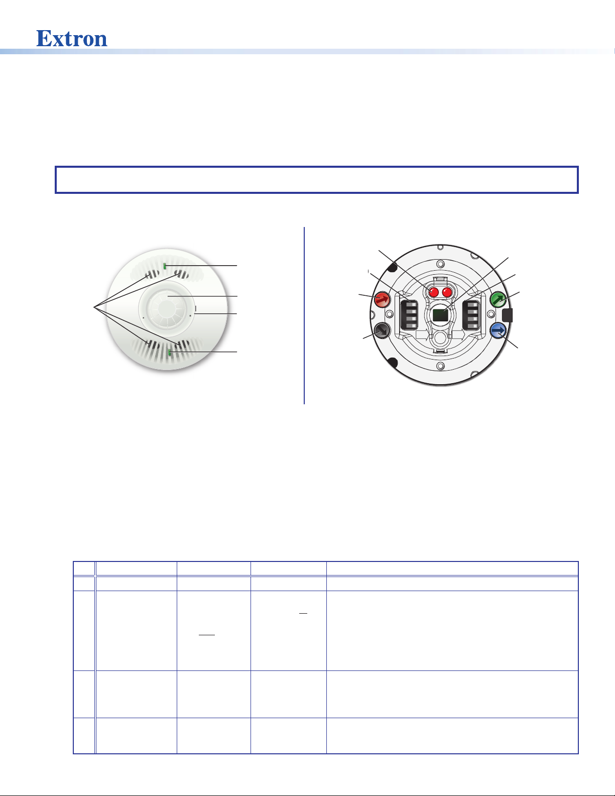
Front Panel Features and Control
Red LED
Ultrasonic
Sensors
Ultrasonic (US)
Green LED
(status indicator)
Fresnel Lens
Retainer Ring
Ultrasonic (US)
Green LED
(status indicator)
(status indicator)
DIP Switches (A)
Red Infrared
Sensitivity Dial
Black Timer
Dial
A
1
2
3
4
ON ON
B
1
2
3
4
Infrared Sensor
DIP Switches (B)
Green Ultrasonic
Sensitivity Dial
Blue Photocell
Sensitivity Dial
Figure 1. OCS 100C Front Panel Features
Figure 2. OCS 100C Controls
• Ultrasonic sensors (4) — Detect movement in the room, based on ultrasonic sound waves. The US sensor emits ultrasonic
sound waves into an area and measures the speed of their return to detect the presence of people. Frequency changes are
caused by the movement of people, which is detected by the US waves.
• Ultrasonic (US) Green LED status indicators (2) — Flash when the ultrasonic sensors detect occupancy.
• Fresnel lens — Diffracts the incoming light and directs the light to the infrared sensor.
• Retainer Ring — Holds the optional IR mask in place. Remove to access all controls and DIP switches. Insert the at end of
a small screwdriver into the notch in the retainer ring to lever it up and off.
• Infrared (PIR) Red LED status indicator — Located behind the fresnel lens, these LEDs ash when the infrared sensor
detects occupancy.
• Infrared Sensor — The infrared (PIR) sensor detects the presence of people based on the difference between the heat
generated by moving people versus the ambient room temperature.
• DIP Switches A —
A Switch Function OFF ON Note
1 Not used *Not used Not used Switch is not used.
2 Occupancy
detection
behavior - Dual
technology mode
3 Sensor status
indicators
4 Automatic adjust
reset
*Default and recommended settings
*Mutually
exclusive
(requires both
PIR and US
detection
*LEDs enabled LEDs disabled Setting A3 to OFF provides a visual notication whenever
*Retain
learned sensor
adjustments
Independent
(either PIR or US
detection)
Erase all learned
settings (toggle
ON, then OFF)
If A2 is set to OFF, both the PIR and US sensors must
be triggered (simultaneously) before the OCS reports an
occupancy signal. If A2 is set to ON, the OCS reports
occupancy based on only one of the sensors being
triggered. When only one sensor is desired, set A2 to ON
and adjust the dials accordingly. If A2 is ON, false detection
when the room is not occupied increases.
the PIR or US sensors are triggered. When the visual LED
indicators are a distraction or you want to disable the
ashing LEDs, A3 should be set to ON.
Only applicable when Timer (B3) or Sensitivity adjust (B4) or
both are set to Automatic mode (OFF). Toggling A4 ON then
OFF will reset any stored learned adjustments.
1
Page 2

Occupancy Sensor OCS 100C • Setup Guide (Continued)
• DIP Switches B — (see figure2 on the previous page)
B Switch Function OFF ON Note
1 High Airow
compensator
2 Doorway mount *Disabled Enabled
3 Timer adjust Automatic *Manual Applies to the Timer (black), Infrared sensitivity (red), and Ultrasonic
4 Sensitivity adjust Automatic *Manual
*Default and recommended settings
NOTE: B3 and B4 must be set to ON for Manual mode, in order to adjust the timer, infrared sensitivity, and US sensitivity
dials manually.
• Black Timer Dial — The occupancy sensor has a built in timer feature. Use the black timer dial to set the amount of time
before the sensor triggers OFF. The factory default setting is 8 minutes.
• Timer range — 8 minutes to 42 minutes.
• Full counter clock wise (CCW) = 8 minutes
• Full clock wise (CW) = 42 minutes
• Timer operation —
• When the sensor detects motion, it instantly triggers ON.
• Once occupancy is no longer detected, the timer begins. If no motion is detected and the timer expires, then the
sensor triggers OFF.
*Disabled Enabled If enabled (set to ON) the sensor will not detect minor changes
and movement. This could result in missed detection, with a low
trigger-on threshold.
sensitivity (green) adjustment dials.
• Setting to Manual mode allows for more predicted behavior
and is better suited for automating AV applications.
• Setting to Automatic mode allows the sensor to learn over
time the ideal timer and sensitivity adjustments for the space
and usage trends. This is better suited for automating lighting
applications.
• All adjustment dials are disabled when set to Automatic (OFF).
NOTE: If it takes too long for the OCS to turn off when the room is unoccupied, adjust the timer to 8 minutes and
extend the timer via the configuration of the connected control processor. This setup reduces false detection.
• Test mode (8 second timer):
• Red Infrared Sensitivity Dial — Adjust this dial to increase or decrease infrared sensitivity.
• Green Ultrasonic Sensitivity Dial — Adjust this dial to increase or decrease ultrasonic sensitivity.
• Blue Photocell Sensitivity Dial — The photocell prevents the sensor from triggering on when the area is adequately lit with
2
1. Open the retainer ring.
2. Rotate the black timer dial to about midway (50% or 12 o’clock).
3. Return to minimum setting (full CCW).
4. The timer will remain in the 8 second test mode for 1 hour, then automatically reset to 8 minutes.
5. To manually force the timer out of the 8 second test mode, turn the timer adjustment approximately 1/16 inch
clockwise. The setting is slightly above minimum (just above the 8 minute setting).
• Turn clockwise (CW) to increase sensitivity. Minor movements are detected as occupancy.
• Turn counter clockwise (CCW) to decrease sensitivity. Major movements are needed to detect occupancy.
• The factory default setting is at 75%.
• Turn clockwise (CW) to increase sensitivity. Minor movement are detected as occupancy.
• Turn counter clockwise (CCW) to decrease sensitivity. Major movements are needed to detect occupancy.
• The factory default setting is at 50%.
natural light and motion is detected. The sensor must be mounted directly over an area that is representative of the average,
natural room lighting. Before setting the photocell control, wait until the natural light is brightest (optional).
Adjust this dial to increase or decrease photocell sensitivity.
• Turn counter clockwise to decrease photocell sensitivity, causing it to activate with less light.
• Turn clockwise to increase photocell sensitivity, requiring brighter light to activate the sensor.
• Factory default is 100% (full clockwise) — Photocell sensor is disabled.
• Range — 10 to 1000 LUX
Page 3
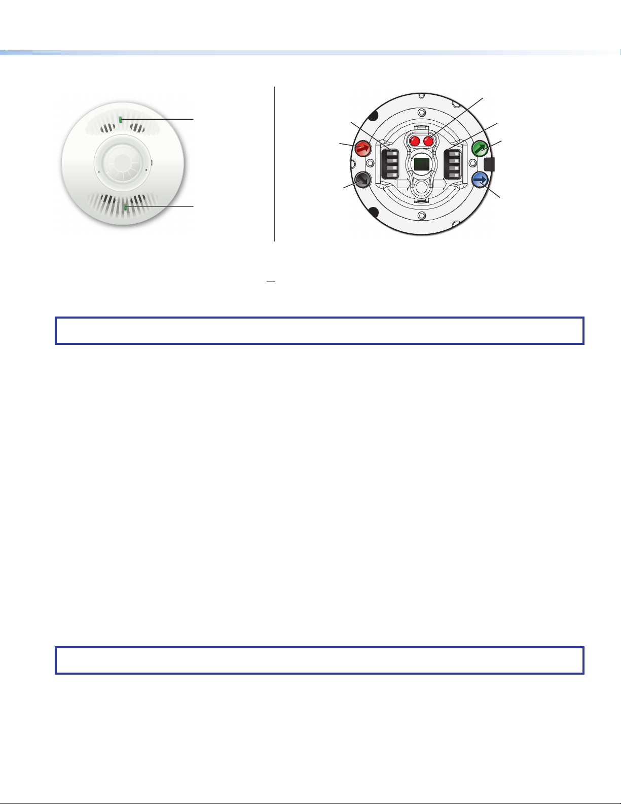
Recommended Setup
Blue Photocell
Sensitivity Dial
Red Infrared
Sensitivity Dial
Green Ultrasonic
Sensitivity Dial
DIP Switches (B)
DIP Switches (A)
1
A
2
3
4
ON ON
1
B
2
3
4
1
2
3
4
1
2
3
4
Infrared (PIR)
Red LED
(status indicator)
Black Timer Dial
1
2
3
4
1
2
3
4
Infrared (PIR)
Red LED
Ultrasonic (US)
Green LED
(status indicator)
Ultrasonic (US)
Green LED
(status indicator)
DIP Switches (A)
Red Infrared
Sensitivity Dial
Black Timer Dial
A
1
2
3
4
ON ON
B
1
2
3
4
Figure 3. OCS 100C Front Panel Features and Controls
With the OCS in the default or recommended settings (A2 OFF), the OCS requires both the IR sensor AND the US sensor to
detect occupancy to turn ON. Only one sensor (PIR or US) needs to trigger to reset the timer for the OCS to remain ON while the
room is still occupied. When the OCS is in the OFF state, no occupancy is detected.
Follow these steps to setup the OCS to detect occupancy with minimal false detection:
NOTE: We recommend using the OCS 100C in the default settings when beginning the setup or the test mode. If needed,
make slight adjustments at a time from the default sensitivity settings.
1. Keep all the DIP switches and rotary dials in the default positions.
2. Set the OCS in Test Mode.
3. Enter the room several times to verify if the IR detector is detecting movement (red LEDs ash).
• If the red LEDs ash when entering the room, the default red infrared sensitivity dial is set correctly.
• Verify the red LEDs ash with movement throughout the room.
• If the red LEDs do not ash, turn the red infrared sensitivity dial to decrease or increase IR sensitivity, until the red LEDs
always ash when entering the room or making movements throughout the room.
• To avoid false detections when the room is unoccupied, do not adjust the sensor too sensitively.
4. Enter the room and verify if the US detector is detecting movement (green LEDs ash).
• If the green LEDs ash when entering the room, the default green ultrasonic range dial is set correctly. This sensor is very
sensitive.
• Verify the green LEDs ash with movement throughout the room.
• If the green LEDs do not ash, turn the green ultrasonic range dial to decrease or increase US sensitivity, until the green
LEDs always ash when entering the room or making movements throughout the room.
• To avoid false detections when the room is unoccupied, do not adjust the sensor too sensitively.
5. Leave the room and close the door. Wait until the Digital output state, relay or red and green LEDs stay OFF. Wait several
minutes to ensure there are no false detections.
• If the door remains open, the US sensor may detect changes.
• If possible, wait longer, to conrm no IR or US change is registered.
6. Enter the room again, to conrm the Digital input state relay, red and green LEDs turn ON.
(status indicator)
DIP Switches (B)
Green Ultrasonic
Sensitivity Dial
Blue Photocell
Sensitivity Dial
NOTE: After going through these steps and verifying the OCS is setup to accommodate the room, do not adjust the DIP
switches or dials.
Automatic Mode
Out of the box, the OCS 100C can be setup in Automatic Mode, where no manual sensitivity adjustments are needed and
sensitivity learning and adjustments are made automatically. For simple setup, we recommend keeping the OCS in the default
settings and ipping the B4 Dip switch to the OFF (Auto) position. The OCS is ready to mount (see Installation on page5).
3
Page 4

Occupancy Sensor OCS 100C • Setup Guide (Continued)
Mask Patterns and Sensor Coverage
An included infrared mask may be needed to achieve the desired sensory coverage. Any area masked will block the PIR sensor
from detecting motion in that area.
NOTE: Mount the OCS 6 to 8 feet (1.8 to 2.4 m) away from HVAC vents and high air flow areas
Hallway
Center Ceiling Mount
(mask blocks sensor seeing
out doorway into hallway)
Conference
Room Mask
Full Mask with
selected areas
cut out
180º Mask Full Mask
Hallway
Corner Ceiling Mount
(no mask needed)
No Mask Needed
Using the Infrared Mask (included)
Rectangular
Areas
Over the Door Specific Areas to Mask
Typical Mask Patterns
22'
(7 m)
12'
(4 m)
(max Disabled)
3
Appliance Control
Threshold
Not Used
U.S. Patents: 6151529, 5946209, 5699243, 5640143, 6415205,
32'
(10 m)
23'
(7 m)
67E4
6078253, D404326, 6222191, 5986357, 6759954
Extron Headquarters
+1.800.633.9876 (Inside USA/Canada Only)
Extron USA - West
+1.714.491.1500 +1.714.491.1517 FAX
OCS 100C
www.extron.com
68-3155-52 Rev. A
45'
(14 m)
64'
(20 m)
Sensor Coverage
Center of
Figure 4. Mask Patterns and Sensor Coverage Diagrams
4
Sensory Coverage
US Minor Motion
US Major Motion
NOTE: These coverage dimensions are achieved when the
OCS100C is installed 10 feet (3 m) above the coverage area.
IR Minor Motion
IR Major Motion
Page 5

Installation
y
e nuts.
Installation Method 1
OCS 100C Parts
S
C
Nut
Washer
Cutting End
Threaded
Mounting Post
Cover Plate
Ceiling
Mounting
Post
Cover Plate
2
Secure mounting
post to the ceiling tile with
nut and washer.
1
Twist and lock threaded
mounting post into the
cover plate. Drill into
ceiling tile.
30˚ Adjustment
Adjustment Knobs
Red: Infrared Range - 75% Default
Black: Timer - 8 min to 42 max - min Default
Green: Ultrasonic Range -50% Default
Blue: Photocell - max Default
Switch Settings: All switches OFF for full automatice oper
A1 Not Used
A2 Threshold: OFF = low sensitivity, ON = high sensitivity
A3 LED Control: OFF = LEDs active, ON = LEDs disabled
A4 Automatic Adjust Reset: Toggle to reset
B1 Strong Airow Compensator: OFF = disable, ON = enable
B2 Over Doorway Mounting: OFF = disable, ON = enable
B3 Timer Adjust: OFF = automatic, ON = manual
B4 Sensitivity Adjust: OFF = automatic, ON = manual
Appliance Control
67E4
Extron Headquarters
+1.800.633.9876 (Inside
Ext
+1.714.491.1500 +1.714.
r
on USA - West
www.extron.com
68-3155-52 Rev. A
U
S
A/
C
anada
491.1517
FAX
U.S. Patents: 6151529, 5946209, 5699243, 5640143, 6415205,
6078253, D404326, 6222191, 5986357, 6759954
OCS 100C
Only)
Made in China
Sensor Coverage
Center of
R
a
n
g
with the arrow on the twist-lock cover
e
Match either arrow shown here
o
f
a
d
plate. Then inserts the tabs into
j
u
s
t
m
e
n
t
the slots. Twist until
ratchet action indicates
(
c
l
i
c
k
t
engagement.
u
Blue: Occupancy control output
Connections
Black : Ground
Grey: Occupancy &
Red: +24VDC
Photocell control
Blue/White = co
Relay Conta
Black/White = N.C
Yello
outp
ation
w/Wh
ut
cts:
mmon
ite = N.O.
.
Conference Room
Mask
Full Mask
r
n
)
Sensor Body
*
*
180º Mask
Infrared Lens w/
Retainer Ring
*
NOTE: *Only use a mask if the PIR sensor needs to be blocked.
Only one mask should be installed at any given time.
Ceiling
Cover Plate
Sensor Body
od
5
Attach sensor body to cover plate
by aligning arrows and twist lock
into place.
Installation Method 2
Ceiling
4
Connect building wiring to
wiring harness with wire nuts.
3
Insert wiring through
mounting post.
Nut and Washer (2 ea)
1
Secure cover
plate to the ceiling.
Mounting Bolts (2)
ATTENTION:
• All structural steps and electrical installation must be performed
by qualied personnel in accordance with local and national
Ceiling
3
Connect building wiring to
wiring harness with wir
building codes and electrical codes.
• Toute étape structurelle et installation électrique, doit être
effectuée par un personnel qualié, conformément aux codes
du bâtiment, aux codes incendie et sécurité, et aux codes
électriques, locaux et nationaux.
• Only connect to Class III SELV systems.
• Connectez l’unité uniquement à des systèmes fonctionnant en
2
Insert wiring through
cover plate.
Sensor Body
4
Screw and mount the
twist-lock cover plate.
très basse tension de sécurité (TBTS) de classe III.
Figure 5. Installation Diagram
5
Page 6

Occupancy Sensor OCS 100C • Setup Guide (Continued)
Extron
Mod
Gr
Devices
PC 1224 Wiring
ATTENTION:
• Do not connect power to the device until you have read the ATTENTION: notices on the next page.
• Ne branchez pas l’alimentation à l’appareil avant d’avoir lu les mises en garde «ATTENTION: » de la page suivante.
• Remove power from the system before making any connections.
• Mettez le système hors tension avant d’effectuer tout raccordement.
• The controller and the OCS 100C must share a common ground connection to avoid ground loops and a difference in
grounding potential.
• Le contrôleur et l’OCS 100C doivent partager une connexion de mise à la terre commune pour éviter les risques de
boucles de terre et une différence dans le potentiel de terre.
The OCS 100C requires 24 VDC to power. If the sensor is connected to a device that does not provide 24VDC, use the included
PC1224 power module:
1. Connect a 12 VDC power source to the 12 VDC input on the supplied PC 1224 power converter (see gure6).
2. Wire the PC 1224 24 VDC, 75 mA max connector to the black and red wires on the OCS100C.
A 12 VDC, 1.25 A max pass-through is available to power additional 12 VDC devices.
OCS 100C Wiring Diagram
PC 1224
Power Module
PC 1224
External Power
Supply (12 VDC)
Ground
(Black)
+12 V (Red)
ound all
Ground (Black)
+12 V (Red)
12V
1.5 A MAX
IN
www.extron.com
POWER
12V
1.0A MAX
OUT
24V
75 mA MAX
OUT
33-2665-01 B
1.25 A MAX
12V
COM 1 DIGITAL I/OCOM 2
G
G
RTSCTS
Tx Rx
Tx Rx
VOL
RELAYS
VCG-S+V +S GC12
IPCP PRO 250
Control Processor
12 4G
PWR OUT = 6W
+24 V (Red)
Ground (Black)
Occupancy Control
Signal (Blue)
IPCP PRO 250
MAC: 00-05-A6-XX-XX-XX
S/N: ####### E######
3
eBUS
IR/S
SG
l
Extron
OCS 100C
Occupancy Sensor
LAN
Figure 6. OCS 100C Wiring Diagram
Wire Color Connections Note
Power
Black Ground Shared with all of the outputs.
Red +24 VDC Power input
Occupancy Control Outputs
Blue Occupancy control output When wiring the blue wire of the OCS to Extron products with Digital or FLEX
Blue/White Common Relay contacts could be used to trigger third party devices, such as HVAC, based on
Black/White Normally closed when unoccupied
Yellow/White Normally open when unoccupied
Occupancy and Lighting Output
Gray Occupancy and photocell control
output
6
Input ports, congure the ports as Input without pull up. The sensor provides
approximately 21 VDC in the ON state and 0 VDC in the OFF state. Use the shared
black ground wire
occupancy.
Typically used for lighting applications. When wiring the gray wires of the OCS to
Extron products with Digital or FLEX Input ports, congure the ports as Input without
pull up. The output state will remain OFF 0 VDC when occupancy is detected but
there is high amount of ambient or natural light in the room. Only when there is low
or no ambient or natural light in the room and occupancy is detected will the output
state trigger ON 21 VDC. Use the shared black ground wire.
Page 7

Troubleshooting
Problem Possible Cause Test Solution
Sensor remains ON. Constant noise. Reduce both green and red
knobs by 1/8 (15%) turn or
remove noise source.
Sensor remains OFF Sensitivity is set too low. Increase both green and red
knobs by 1/8 (15%) turn.
Sensor remains on too long. Timer setting is too high. Check DIP switch settings. Reduce timer setting.
Hallway trafc turns sensor
on.
Infrared sensor can see into
the hallway.
Put sensor in timer test mode
and walk the hallway.
Move sensor to a less noisy
area within the room.
Move the sensor. If the A2
DIP switch is set to OFF,
set green and red knobs to
normal levels.
Move sensor, so it cannot see
into the hallway or install the
IR blocks.
Safety Instructions
For information on safety guidelines, regulatory compliances, EMI/EMF compatibility, accessibility, and related topics, see the
Extron Safety and Regulatory Compliance Guide on the Extron website.
FCC Class A Notice
This equipment has been tested and found to comply with the limits for a Class A digital device, pursuant to part 15 of the
FCC rules. The Class A limits provide reasonable protection against harmful interference when the equipment is operated in a
commercial environment. This equipment generates, uses, and can radiate radio frequency energy and, if not installed and used
in accordance with the instruction manual, may cause harmful interference to radio communications. Operation of this equipment
in a residential area is likely to cause interference. This interference must be corrected at the expense of the user.
NOTE: For more information on safety guidelines, regulatory compliances, EMI/EMF compatibility, accessibility, and related
topics, see the Extron Safety and Regulatory Compliance Guide on the Extron website.
Power Attention
ATTENTION:
• These products are intended for use with a UL Listed LPS type power source.
• Ces produits doivent être utilisés avec une source d’alimentation de type LPS certiée UL.
• Use of a non-LPS or unlisted power supply will void all regulatory compliance certication.
• L’utilisation d’une source d’alimentation non-listée ou non-listéeLPS annulera toute certication de conformité
réglementaire.
• Unless otherwise stated, the AC/DC adapters are not suitable for use in air handling spaces or in wall cavities. The
power supply is to be located within the same vicinity as the Extron AV processing equipment in an ordinary location,
Pollution Degree 2, secured to the equipment rack within the dedicated closet, podium, or desk.
• Sauf mention contraire, les adaptateurs CA/CC ne conviennent pas à une utilisation dans les espaces d’aération ou dans
les cavités murales. La source d’alimentation doit être placée à proximité de l’équipement Extron dans un emplacement
ordinaire soumis à un degré de pollution de catégorie II, solidement xé au rack d’équipement d’une baie technique,
d’un pupitre, ou d’un bureau.
• The installation must always be in accordance with the applicable provisions of National Electrical Code ANSI/NFPA 70,
article 725 and the Canadian Electrical Code part 1, section 16.
• Cette installation doit toujours être conforme aux dispositions applicables du Code américain de l’électricité (National
Electrical Code) ANSI/NFPA 70, article 725, et du Code canadien de l’électricité, partie1, section16.
• The power supply shall not be permanently xed to building structure or similar structure.
• La source d’alimentation ne devra pas être xée de façon permanente à la structure de bâtiment ou à d’autres structures
similaires.
7
Page 8

For information on safety guidelines, regulatory compliances, EMI/EMF compatibility, accessibility, and related topics, see the
Extron Safety and Regulatory Compliance Guide on the Extron website.
© 2017-2019 Extron Electronics — All rights reserved. www.extron.com
All trademarks mentioned are the property of their respective owners.
Worldwide Headquarters: Extron USA West, 1025 E. Ball Road, Anaheim, CA 92805, 800.633.9876
68-3155-51 Rev. G
01 19
 Loading...