

Page 1
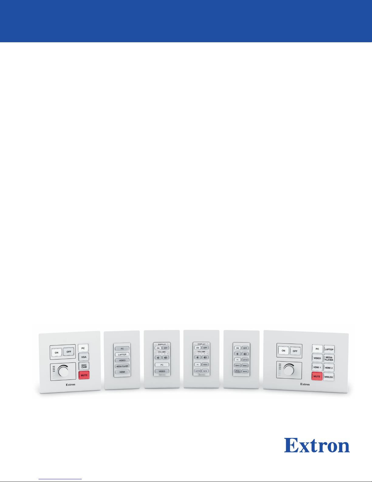
IP Link Pro® Products
Network Button Panels
NBP Network Button Panels
User Guide
NBP 106 DNBP 105 DNBP 100 NBP 200NBP 110 DNBP 108 D
68-3267-01 Rev. A
03 19
Page 2
Safety Instructions
Safety Instructions • English
WARNING: This symbol, ,when used on the product, is
intended to alert the user of the presence of uninsulated dangerous
voltage within the product’s enclosure that may present a risk of electric
shock.
ATTENTION: This symbol, , when used on the product, is intended
to alert the user of important operating and maintenance (servicing)
instructions in the literature provided with the equipment.
For information on safety guidelines, regulatory compliances, EMI/EMF
compatibility, accessibility, and related topics, see the Extron Safety and
Regulatory Compliance Guide, part number 68-290-01, on the Extron
website, www.extron.com.
Sicherheitsanweisungen • Deutsch
WARNUNG: Dieses Symbol auf dem Produkt soll den Benutzer
darauf aufmerksam machen, dass im Inneren des Gehäuses dieses
Produktes gefährliche Spannungen herrschen, die nicht isoliert sind und
die einen elektrischen Schlag verursachen können.
VORSICHT: Dieses Symbol auf dem Produkt soll dem Benutzer in
der im Lieferumfang enthaltenen Dokumentation besonders wichtige
Hinweise zur Bedienung und Wartung (Instandhaltung) geben.
Weitere Informationen über die Sicherheitsrichtlinien, Produkthandhabung,
EMI/EMF-Kompatibilität, Zugänglichkeit und verwandte Themen finden Sie in
den Extron-Richtlinien für Sicherheit und Handhabung (Artikelnummer
68-290-01) auf der Extron-Website, www.extron.com.
Instrucciones de seguridad • Español
ADVERTENCIA: Este símbolo, , cuando se utiliza en el producto,
avisa al usuario de la presencia de voltaje peligroso sin aislar dentro del
producto, lo que puede representar un riesgo de descarga eléctrica.
ATENCIÓN: Este símbolo, , cuando se utiliza en el producto, avisa
al usuario de la presencia de importantes instrucciones de uso y
mantenimiento recogidas en la documentación proporcionada con el
equipo.
Para obtener información sobre directrices de seguridad, cumplimiento
de normativas, compatibilidad electromagnética, accesibilidad y temas
relacionados, consulte la Guía de cumplimiento de normativas y seguridad
de Extron, referencia 68-290-01, en el sitio Web de Extron, www.extron.com.
Instructions de sécurité • Français
AVERTISSEMENT : Ce pictogramme, , lorsqu’il est utilisé sur le
produit, signale à l’utilisateur la présence à l’intérieur du boîtier du
produit d’une tension électrique dangereuse susceptible de provoquer
un choc électrique.
Istruzioni di sicurezza • Italiano
AVVERTENZA: Il simbolo, , se usato sul prodotto, serve ad
avvertire l’utente della presenza di tensione non isolata pericolosa
all’interno del contenitore del prodotto che può costituire un rischio di
scosse elettriche.
ATTENTZIONE: Il simbolo, , se usato sul prodotto, serve ad
avvertire l’utente della presenza di importanti istruzioni di funzionamento
e manutenzione nella documentazione fornita con l’apparecchio.
Per informazioni su parametri di sicurezza, conformità alle normative,
compatibilità EMI/EMF, accessibilità e argomenti simili, fare riferimento
alla Guida alla conformità normativa e di sicurezza di Extron, cod. articolo
68-290-01, sul sito web di Extron, www.extron.com.
Instrukcje bezpieczeństwa • Polska
OSTRZEŻENIE: Ten symbol, , gdy używany na produkt, ma na celu
poinformować użytkownika o obecności izolowanego i niebezpiecznego
napięcia wewnątrz obudowy produktu, który może stanowić zagrożenie
porażenia prądem elektrycznym.
UWAGI: Ten symbol, , gdy używany na produkt, jest przeznaczony do
ostrzegania użytkownika ważne operacyjne oraz instrukcje konserwacji
(obsługi) w literaturze, wyposażone w sprzęt.
Informacji na temat wytycznych w sprawie bezpieczeństwa, regulacji
wzajemnej zgodności, zgodność EMI/EMF, dostępności i Tematy pokrewne,
zobacz Extron bezpieczeństwa i regulacyjnego zgodności przewodnik, część
numer 68-290-01, na stronie internetowej Extron, www.extron.com.
Инструкция по технике безопасности • Русский
ПРЕДУПРЕЖДЕНИЕ: Данный символ, , если указан
на продукте, предупреждает пользователя о наличии
неизолированного опасного напряжения внутри корпуса
продукта, которое может привести к поражению электрическим
током.
ВНИМАНИЕ: Данный символ, , если указан на продукте,
предупреждает пользователя о наличии важных инструкций
по эксплуатации и обслуживанию в руководстве,
прилагаемом к данному оборудованию.
Для получения информации о правилах техники безопасности,
соблюдении нормативных требований, электромагнитной
совместимости (ЭМП/ЭДС), возможности доступа и других
вопросах см. руководство по безопасности и соблюдению
нормативных требований Extron на сайте Extron: ,
www.extron.com, номер по каталогу - 68-290-01.
安全说明 • 简体中文
警告: 产品上的这个标志意在警告用户该产品机壳内有暴露的危险 电压,
有触电危险。
ATTENTION : Ce pictogramme, , lorsqu’il est utilisé sur le produit,
signale à l’utilisateur des instructions d’utilisation ou de maintenance
importantes qui se trouvent dans la documentation fournie avec le
matériel.
Pour en savoir plus sur les règles de sécurité, la conformité à la
réglementation, la compatibilité EMI/EMF, l’accessibilité, et autres sujets
connexes, lisez les informations de sécurité et de conformité Extron, réf.
68-290-01, sur le site Extron, www.extron.com.
注意: 产品上的这个标志意在提示用户设备随附的用户手册中有
重要的操作和维护(维修)说明。
关于我们产品的安全指南、遵循的规范、EMI/EMF 的兼容性、无障碍
使用的特性等相关内容,敬请访问 Extron 网站 , www.extron.com,参见
Extron 安全规范指南,产品编号 68-290-01。
Page 3
安全記事 • 繁體中文
警告: 若產品上使用此符號,是為了提醒 使用者,產品機殼內存在著
可能會導致觸電之風險的未絕緣危險電壓。
注意 若產品上使用此符號,是為了提醒使用者,設備隨附的用戶手冊中有
重 要 的 操 作 和 維 護( 維 修 )説 明 。
有關安全性指導方針、法規遵守、EMI/EMF 相容性、存取範圍和相關主題的詳細資
訊,請瀏覽 Extron 網站:www.extron.com,然後參閱《Extron 安全性與法規
遵守手冊》,準則編號 68-290-01。
安全上のご注意 • 日本語
警告: この記 号 が製品上に表示されている場合は、筐体内に絶縁されて
いない高電圧が流れ、感電の危険があることを示しています。
注意:この記号 が製品上に表示されている場合は、本機の取扱説明書に
記載されている重要な操作と保守( 整備)の 指示についてユーザーの注 意
を喚起するものです。
安全上のご注意、法規厳守、EMI/EMF適合性、その他の関連項目に
つ い て は 、エ クスト ロ ン の ウェ ブ サ イト www.extron.com よ り 『 Extron Safety
and Regulatory Compliance Guide』 ( P/N 68-290-01) をご覧ください。
안전 지침 • 한국어
경고: 이 기호 가 제품에 사용될 경우, 제품의 인클로저 내에 있는
접지되지 않은 위험한 전류로 인해 사용자가 감전될 위험이 있음을
경고합니다.
주의: 이 기호 가 제품에 사용될 경우, 장비와 함께 제공된 책자에 나와
있는 주요 운영 및 유지보수(정비) 지침을 경고합니다.
안전 가이드라인, 규제 준수, EMI/EMF 호환성, 접근성, 그리고 관련 항목에
대한 자세한 내용은 Extron 웹 사이트(www.extron.com)의 Extron 안전 및
규제 준수 안내서, 68-290-01 조항을 참조하십시오.
Copyright
© 2019 Extron Electronics. All rights reserved. www.extron.com
Trademarks
All trademarks mentioned in this guide are the properties of their respective owners.
The following registered trademarks
(®)
, registered service marks
Extron Electronics (see the current list of trademarks on the Terms of Use page at www.extron.com):
Extron, Cable Cubby, ControlScript, CrossPoint, DTP, eBUS, EDID Manager, EDID Minder, Flat Field, FlexOS, Glitch Free, GlobalConfigurator,
GlobalScripter, GlobalViewer, Hideaway, HyperLane, IPIntercom, IPLink, KeyMinder, LinkLicense, LockIt, MediaLink, MediaPort,
NetPA, PlenumVault, PoleVault, PowerCage, PURE3, Quantum, Show Me, SoundField, SpeedMount, SpeedSwitch, StudioStation,
SystemINTEGRATOR, TeamWork, TouchLink, V-Lock, VideoLounge, VN-Matrix, VoiceLift, WallVault, WindoWall, XTP, XTPSystems, and ZipClip
Registered Service Mark
(SM)
: S3 Service Support Solutions
AAP, AFL (Accu-Rate Frame Lock), ADSP (Advanced Digital Sync Processing), Auto-Image, AVEdge, CableCover, CDRS (ClassD
Ripple Suppression), Codec Connect, DDSP (Digital Display Sync Processing), DMI (Dynamic Motion Interpolation), DriverConfigurator,
DSPConfigurator, DSVP (Digital Sync Validation Processing), eLink, EQIP, Everlast, FastBite, FOX, FOXBOX, IPIntercom HelpDesk, MAAP,
MicroDigital, Opti-Torque, PendantConnect, ProDSP, QS-FPC (QuickSwitch Front Panel Controller), Room Agent, Scope-Trigger, ShareLink,
SIS, SimpleInstructionSet, Skew-Free, SpeedNav, Triple-Action Switching, True4K, Vector™ 4K, WebShare, XTRA, and ZipCaddy
(SM)
, and trademarks
Registered Trademarks
Trademarks
(™)
(™)
are the property of RGB Systems, Inc. or
(®)
Page 4
FCC Class A Notice
This equipment has been tested and found to comply with the limits for a Class A digital
device, pursuant to part15 of the FCC rules. The ClassA limits provide reasonable
protection against harmful interference when the equipment is operated in a commercial
environment. This equipment generates, uses, and can radiate radio frequency energy and,
if not installed and used in accordance with the instruction manual, may cause harmful
interference to radio communications. Operation of this equipment in a residential area is
likely to cause interference. This interference must be corrected at the expense of the user.
NOTE: For more information on safety guidelines, regulatory compliances,
EMI/EMF compatibility, accessibility, and related topics, see the “Extron Safety and
Regulatory Compliance Guide” on the Extron website.
Battery Notice
This product contains a battery. Do not open the unit to replace the battery. If the battery
needs replacing, return the entire unit to Extron (for the correct address, see the Extron
Warranty section on the last page of this guide).
CAUTION: Risk of explosion. Do not replace the battery with an incorrect type. Dispose
of used batteries according to the instructions.
ATTENTION : Risque d’explosion. Ne pas remplacer la pile par le mauvais type de pile.
Débarrassez-vous des piles usagées selon le mode d’emploi.
Page 5
Conventions Used in this Guide
Notifications
The following notifications are used in this guide:
CAUTION: Risk of minor personal injury.
ATTENTION : Risque de blessure mineure.
ATTENTION:
• Risk of property damage.
• Risque de dommages matériels.
NOTE: A note draws attention to important information.
TIP: A tip provides a suggestion to make working with the application easier.
Software Commands
Commands are written in the fonts shown here:
^AR Merge Scene,,Op1 scene 1,1 ^B 51 ^W^C
[01] R 0004 00300 00400 00800 00600 [02] 35 [17] [03]
NOTE: For commands and examples of computer or device responses mentioned
in this guide, the character “0” is used for the number zero and “O” is the capital
letter “o.”
Computer responses and directory paths that do not have variables are written in the font
shown here:
Reply from 208.132.180.48: bytes=32 times=2ms TTL=32
C:\Program Files\Extron
Variables are written in slanted form as shown here:
ping xxx.xxx.xxx.xxx —t
SOH R Data STX Command ETB ETX
Selectable items, such as menu names, menu options, buttons, tabs, and field names are
written in the font shown here:
From the File menu, select New.
Click the OK button.
Specifications Availability
Product specifications are available on the Extron website, www.extron.com.
Extron Glossary of Terms
A glossary of terms is available at http://www.extron.com/technology/glossary.aspx.
Page 6

Page 7

Contents Contents
Introduction ...................................................1
Before You Begin ................................................ 1
What This Guide Covers ................................. 1
Conventions Used in This Guide ..................... 1
About the Network Button Panels ....................... 1
Decorator-style Models ................................... 2
US Gang Models ............................................ 2
Features ......................................................... 3
Application Diagrams .......................................... 4
PC System Requirements ................................... 5
Hardware Features and Installation ...........6
Overall Configuration Procedure ......................... 7
Installation Step 1: Get Ready............................. 8
Installation Step 2: Prepare the Installation Site .... 9
Accessibility and Americans with Disabilities
Act (ADA) Compliance ................................... 9
Site Preparation ............................................ 10
Installation Step 3: Change Buttons, Button
Labels, a Bezel, or Wallplate (optional) ............. 11
Instructions for Decorator-style Models ......... 11
Instructions for US Gang Models .................. 13
Installation Step 4: Cable All Devices ................ 14
Rear and Side Panel Features and Cabling ... 15
Installation Step 5: Set up the NBP for
Network Communication ................................. 17
Installation Step 6: Configure the System .......... 17
Installation Step 7: Test and Troubleshoot ......... 17
Installation Step 8: Complete the Physical
Installation ....................................................... 18
Mounting .......................................................... 18
Software-Based
Configuration and Control .........................28
Configuration and Control: an Overview ............ 28
Basic Setup Steps: a Guide to this Section
and Other Resources ...................................... 29
Downloading the Software and Getting Started ... 29
Locating Software, Firmware, and
Driver Files on the Extron Website ................ 29
Things to Do After Installing GC and
Before Starting a Project .............................. 31
Using GC: Helpful Tips ..................................... 31
Troubleshooting ................................................ 32
Power Connections ...................................... 32
Data Connections ......................................... 32
Device Control Connections and
Configuration ............................................... 32
Reference Information ...............................34
Network Port Requirements.............................. 34
Secure Sockets Layer (SSL) Certificates ........... 34
Firmware Updates .......................................36
Determining the Firmware Version ..................... 36
Using Toolbelt Software ................................ 36
Using a Browser ........................................... 36
Updating the Firmware ..................................... 37
Locating and Downloading the Firmware ...... 37
Installing firmware ......................................... 37
Operation ..................................................... 21
Front Panel Features ......................................... 21
Wallplates and Bezels ................................... 23
Buzzer (Decorator-style Models Only) ........... 23
Buttons......................................................... 24
Volume Controls and LEDs ........................... 24
Reset Features and Resetting the Unit .............. 26
Locating the Reset Button and LED .............. 26
Resetting the Unit ......................................... 26
Network Button Panels • Contents vii
Page 8

Network Button Panels • Contents viii
Page 9

Introduction
This section covers the following basic information you should know about this guide and
the product before installation:
• Before You Begin
• About the Network Button Panels
• Application Diagrams
• PC System Requirements
Before You Begin
What This Guide Covers
This user guide provides instructions for an experienced installer to install an Extron Network
Button Panel (NBP). This guide includes detailed information and recommends best
practices for cabling the NBP. It provides a brief overview of the configuration process, and
reference information.
Configure the IP-related settings of the NBP using Toolbelt software. Then you can
configure the control processor and overall system using Extron Global Configurator
Professional (GCProfessional) or Global Configurator Plus (GC Plus), or program them using
GlobalScripter. The system configuration includes button configurations for the NBPs.
This guide does not contain instructions on detailed software-related setup steps or details
of configuration within the software. Those are covered in the help files for each software
package or scripting program. The software help files describe how to use each program to
download drivers, add AV devices to a configuration, configure basic functions, and set up
schedules, macros, e-mail alerts, button configurations, and the like.
Conventions Used in This Guide
• Throughout this guide a Network Button Panel is also referred to as an “NBP” or “button
panel.”
• Global Configurator software is referred to as “GC,” which can be run as Global
Configurator Professional or Global Configurator Plus.
• The GlobalViewer Enterprise application is sometimes referred to as “GVE.”
About the Network Button Panels
The NBP Network Button Panels allow users to remotely control AV equipment in
conjunction with an Extron IPCPPro or IPLPro control processor or HCR102 receiver (part
of an HC400 Series system). This equipment includes, but is not limited to, display devices,
switchers, source devices, and various other items such as lights, a projector lift, or a screen
motor.
See the help files for the configuration and programming software to determine how many
NBPs can be included in a system.
Network Button Panels • Introduction 1
Page 10
The IP settings for NBPs are configured via Toolbelt software. Configure button behavior
33-1720-22
B
C
U
S
CAN ICES-3(A)/NMB-3(A)
LISTED
ACCESSORY
I.T.E.
E146728
on
V
M
L
e
e
as part of the system configuration you create within a Global Configurator project or
GlobalScripter programming. The project configuration is saved, built, and uploaded into
the IPCPPro or IPLPro control processor or the HCR102 receiver.
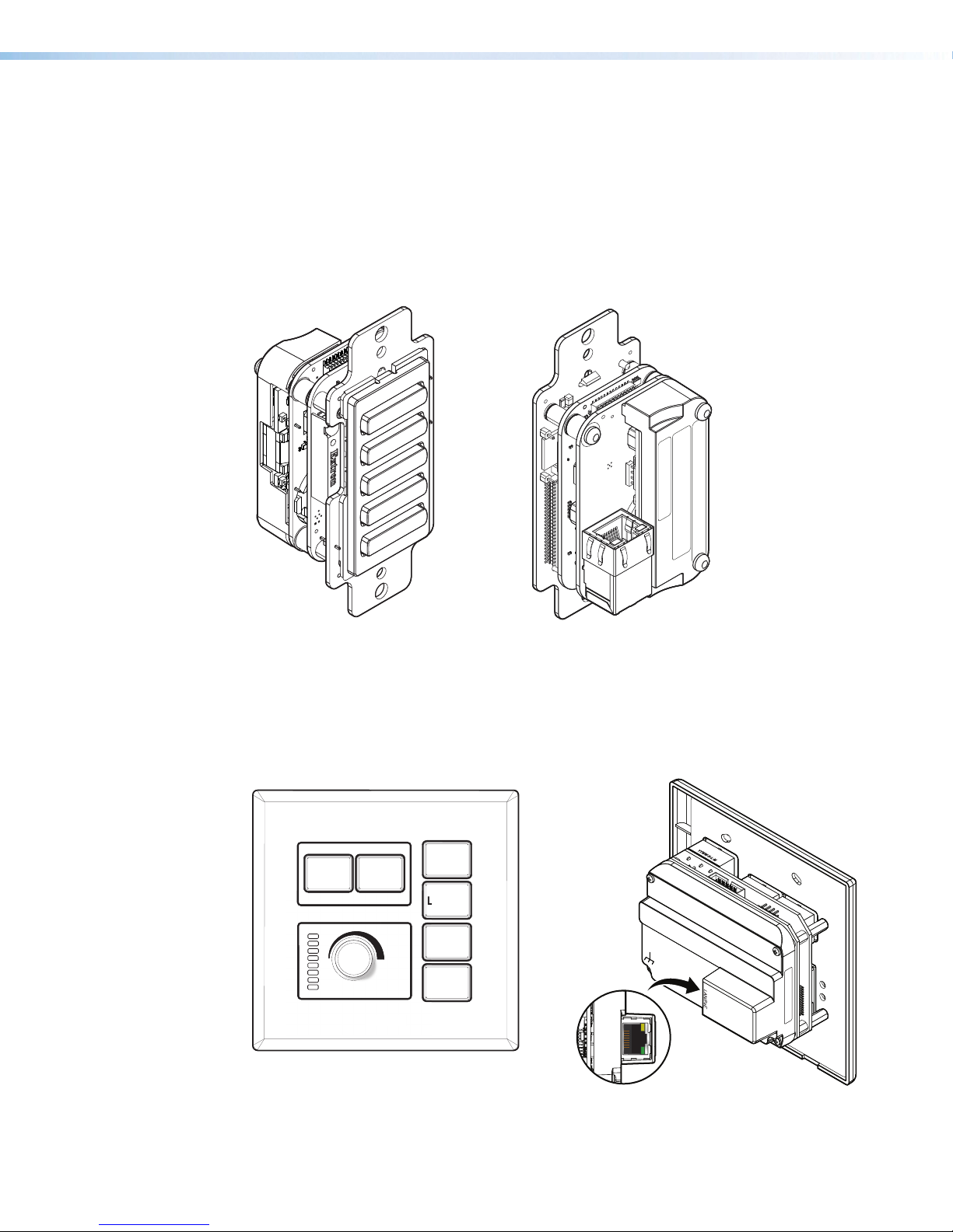
Decorator-style Models
The NBP 105 D, NBP 106 D, NBP 108 D, and NBP 110 D feature soft backlit buttons,
fit into a standard US one-gang junction box or mud ring, and include a decorator-style
wallplate.
R
e
e
PC
LAPTOP
VIDEO
MAC: 00-05-A6-XX-XX-XX
S/N: ####### E######
Figure 1. NBP 105 D Front (Left) and Rear (Right) Views Without Wallplate
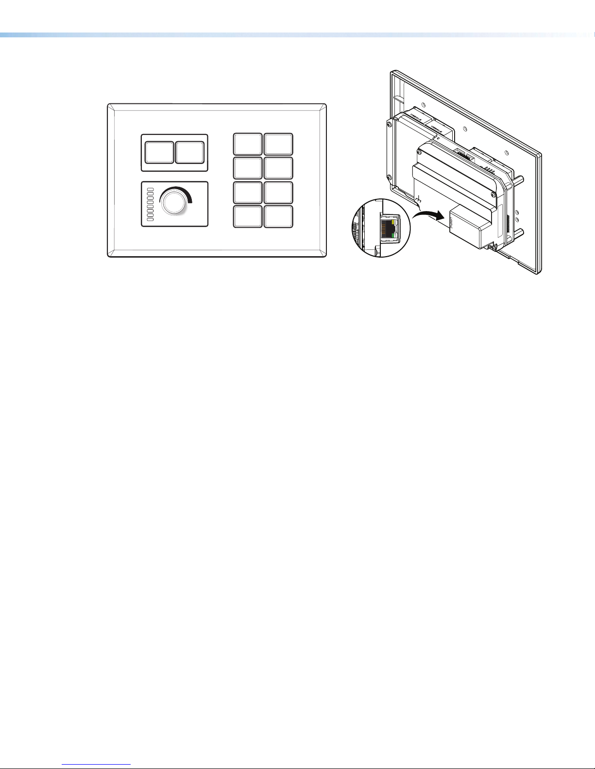
US Gang Models
The NBP 100 and NBP 200 feature hard, translucent buttons that can easily be relabeled.
These models fit into a standard US two-gang (NBP100) or three-gang (NBP200) junction
box or mud ring.
ON
MEDIA PLAYER
HDMI
OFF
Extron
Extr
PC
LAPTOP
VIDEO
MUTE
LAN/PoE
e
YYWW-N- L-M
00-05-A6-XX-XX-XX
MAC: 00-05-A6-XX-XX-XX
S/N: ####### E######
e
Figure 2. NBP 100 Front (Left) and Rear (Right) Views
Network Button Panels • Introduction 2
Page 11
ON
E
o
e
YYWW-N- L-M
e
YYWW-N- L-M
OFF
PC
VIDEO
LAPTOP
MEDIA
PLAYER
YYWW-N- L-M
e
YYWW-N- L-M
e
Features
Extron
xtr
HDMI 1
MUTE
HDMI 2
WIRELESS
e
00-05-A6-XX-XX-XX
MAC: 00-05-A6-XX-XX-XX
S/N: ####### E######
Figure 3. NBP 200 Front (Left) and Rear (Right) Views
General features
• Configurable buttons — The system configuration sets button illumination (levels and
whether each button is lit steadily or blinking) and functions (commands, macros, and
so forth).
• A variety of mounting options — The NBP can be mounted in furniture or a wall, in
a lectern, or in a surface mount box, depending on the model.
• Power over Ethernet (PoE) — The NBPs support power over Ethernet, providing the
unit with both power and an Ethernet signal over a single connector.
Network and configuration features
• Global compatibility — The NBPs use industry standard Ethernet communication
protocols, including DHCP, DNS, HTTP, HTTPS, ICMP, NTP, SFTP, SMTP, SNMP, SSH,
TCP/IP, and UDP/IP.
• Network connection — The NBPs support 10Base-T up to 100Base-T Ethernet
communication.
Network Button Panels • Introduction 3
Page 12

Application Diagrams
Ext
IN
Swit
with
Ex
Document
Came
l
l
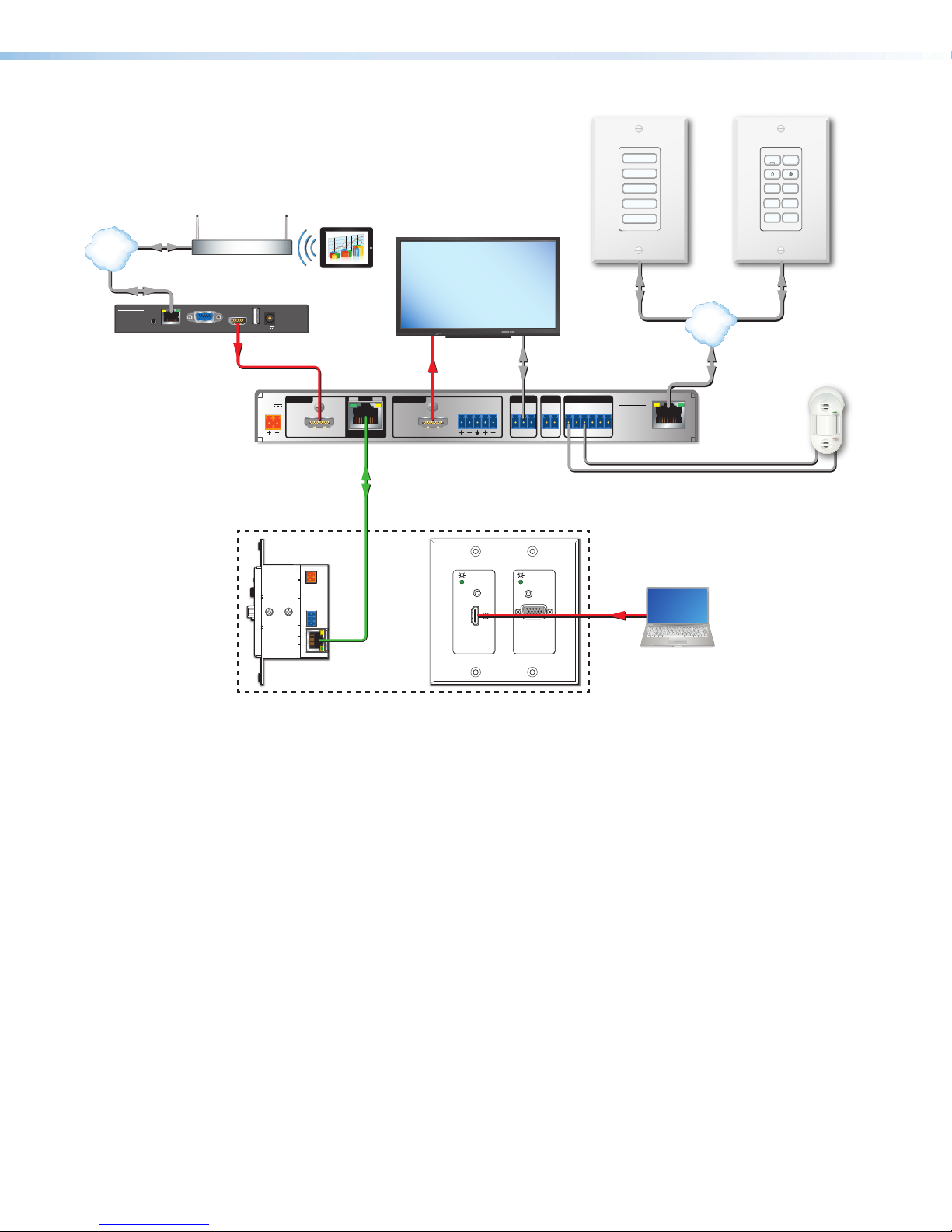
The following figures provide examples of NBP button panels integrated into AV systems.
WiFi
1234
PC
Extron
DTP HDMI 4K
330 Rx
Receiver
SIG LINK
POWER
12V
0.7A MAX
OUTPUTS
AUDIO
DTP IN
LR
OVER DTP
IR
RS-232
TxRx TxRxG
DTP HDMI 4K 330 Rx
Extron
FF 220T
Ceiling Speakers
MODEL 80
HDMI
Laptop
ron
1608 MA
cher
DTP
tension
ra
HDMI HDMI
1
CONFIGURABLE
100-240V ~ -- A MAX
2
50/60 Hz
VGA
RS-232
CATx Cable
12
VARIABLE
LR
AMPLIFIED OUTPUT
RESET
70V - 100W
CLASS 2 WIRING
REMOTE
LAN
Audio
RS-232
TxRx
G
Ethernet
INPUTS
5
3
4
7
SIG LINK
HDMI
HDMI
6
DTP IN
IN1608 MA
OVER DTP
RS-232 IR
TxRx TxRxG
OVER DTP
RS-232 IR
TxRx TxRxG
OUTPUTS
C
8
SIG LINK
A
SIG LINK
OVER DTP
RS-232 IR
B
DTP OUT
TxRx TxRxG
DTP IN
HDMI
AUDIO INPUTS OUTPUTS
LL1R R
3
L2
L4
R
R
L5R
+48V
MIC/LINE
L6
R
2
+48V
RS-232 over DTP
HDMI
POWER
12V
--A MAX
Extron
IPCP Pro 250
STANDBY/ON
PQLS HDMI OPEN/CLOSE FL OFF
Blu-ray Player
USB
IR to Blu-ray
IP Link Pro
Control Processor
Figure 4. An NBP 100 and NBP 100 Application
Tx Rx RTSCTS
COM 1
G
VOL
VCG
TCP/IP
Network
COM 2
DIGITAL I/O
G
Tx Rx
1 2 3 4 G
RELAYS
eBUS
IR/S
1 2 C
+V+S-SG
S G
PWR OUT = 6W
IPCP PRO 250
LAN
FLAT PANEL
Display
Ethernet/PoE
Ethernet
PC
Extron
LAPTOP
MEDIA
VIDEO
PLAYER
HDMI 1
HDMI 2
MUTE
WIRELESS
OFF
ON
Extron
NBP 200
Network Button Pane
Ethernet/PoE
PC
ON OFF
LAPTOP
VIDEO
MUTE
Extron
Extron
NBP 100
Network Button Pane
Network Button Panels • Introduction 4
Page 13
Occupancy Sensor
TCP/IP
Network
Ethernet
Ethernet
ShareLink 200 N
Extron
ShareLink 200 N
Collaboration
Gateway
PC
LAPTOP
VIDEO
Room
Wireless Access
Point
MODEL 80
Tablet
AUDIO
OUT
VGA OUT HDMI OUT
LAN / PoE
POWER
5V
USB 3
2.3A MAX
HDMI
POWER
INPUTS
12V
2.0A MAX
HCR 102
Scaling Receiver
FLAT PANEL
Display
HDMI
SIG
LINK
1
TP
HDMI
OUTPUTS
IN
HDMI/CEC
AUDIO
L R
Twisted Pair
RS-232
COM IR DIGITAL I/O
1 2S GTx Rx G G 3 4 G
MEDIA PLAYER
HDMI
HCR 102
NBP 105 D
Network
Button
Panel
TCP/IP
Network
Ethernet
LAN
ON OFF
PC LAPTOP
HDMI 1 HDMI 2
MEDIA
PLAYER
MUTE
NBP 110 D
Network
Button Panel
Extron
OCS 100W
Wall Mount
Cable (AV)
HCT 102 D
Switching Transmitter
230'
Side Front
Figure 5. A Collaboration System Featuring Network Button Panels
PC System Requirements
To find the minimum hardware and software requirements for the PC you use to configure or
program the system:
• Visit the Download page (http://www.extron.com/download/index.aspx) on the
Extron website and navigate to the web page for the specific software package (such as
Global Configurator). Minimum system requirements are listed in the description section.
In some cases, minimum device firmware version requirements are also listed there.
• If system requirements are not listed on the software package web page, contact an
Extron support representative.
AUDIO IN
HDMI IN
Extron
AUDIO IN
VGA IN
HDMI
Network Button Panels • Introduction 5
Page 14

Hardware Features
and Installation
This section covers the following material:
• Overall Configuration Procedure
• Installation Step 1: Get Ready
• Installation Step 2: Prepare the Installation Site
• Installation Step 3: Change Buttons, Button Labels, a Bezel, or Wallplate
(optional)
• Installation Step 4: Cable All Devices
• Installation Step 5: Set up the NBP for Network Communication
• Installation Step 6: Configure the System
• Installation Step 7: Test and Troubleshoot
• Installation Step 8: Complete the Physical Installation
• Mounting
Network Button Panels • Hardware Features and Installation 6
Page 15

Overall Configuration Procedure
Get ready.
Prepare the installation site.
Change buttons or faceplates, if desired
Cable the NBPs and the control processor or HCR receiver,
Within Global Configurator
(GC Professional or
GC Plus mode):
Create a new GC Professional or GC Plus project
and add the control processor or receiver to it.
Create monitors, schedules, timers, macros,
Add NBP button panels and congure the buttons.
then apply power.
Configure the IP settings of each NBP
and of the control processor or receiver.
If desired or required, install a new
security certicate (via Toolbelt).
Congure ports.
and local variables.
Save the project.
Build and upload the conguration to
the controller or receiver.
See the network
network
communication
communication
setup instructions
setup instructions
on page17.
Cable all devices.
Test the system, make adjustments,
nalize conguration.
Mount the NBPs.
Figure 6. Overall Installation and Configuration Steps
Network Button Panels • Hardware Features and Installation 7
Page 16

Installation Step 1: Get Ready
Use the following checklist to prepare for the installation.
Familiarize yourself with the features of the button panel (see Front Panel Features on
page21 and Rear and Side Panel Features and Cabling on page15)
Download and install the latest version of the software, firmware, and device drivers
needed to discover, configure, or program the control processor or HCR receiver (or
other Extron collaboration system control product) to interact with the NBPs and control
the connected AV products. See the IPCP Pro Series User Guide, IPL Pro Series User
Guide, or HC 400 Series User Guide (avail able from www.extron.com) for details on
software and drivers.
Obtain network information for the unit from the network administrator. You need the
following details for each IPLinkPro device, including the IPCP Pro, IPL Pro, HCR102
(or other collaboration system receiver), and each NBP:
DHCP setting (on or off) Subnet mask User name
Device (NBP) IP address Gateway IP address Passwords
Write down the MAC address of each IPLinkPro device (such as the NBP) to be used.
Obtain model names and setup information for the AV devices to be controlled in the
system.
Each NBP button panel comes with a factory-installed Secure Sockets Layer (SSL)
security certificate. If you intend to install a different SSL certificate, contact your IT
department to obtain the certificate or for instructions on how to obtain one. See
Secure Sockets Layer (SSL) Certificates on page34 for requirements and
guidelines regarding SSL certificates.
Network Button Panels • Hardware Features and Installation 8
Page 17

Installation Step 2: Prepare the Installation Site
Steps and hardware required depend on the model being installed (see Site Preparation
on page10 for details).
ATTENTION:
• Installation and service must be performed by authorized personnel only.
• L’installation et l’entretien doivent être effectués uniquement par un technicien
qualifié.
• Extron recommends installing the NBP into a grounded, UL Listed electrical junction box.
• Extron recommande d’installer le NBP dans un boîtier d’encastrement électrique mis
à la terre, certifié UL.
• If the NBP will be installed into fine furniture, it is best to hire a licenced, bonded
craftsperson to cut the access hole and perform the physical installation so the
surface will not be damaged.
• S’il est prévu d’installer le NBP dans du beau mobilier, il est préférable de faire appel
à un artisan autorisé et qualifié pour couper le trou d’accès et réaliser l’installation de
telle façon que la surface ne soit pas endommagée.
• Follow all national and local building and electrical codes that apply to the installation site.
• Respectez tous les codes électriques et du bâtiment, nationaux et locaux, qui
s’appliquent au site de l’installation.
NOTES:
• For the installation to meet UL requirements and to comply with National Electrical
Code (NEC), the NBP must be installed in a UL Listed junction box. The end user or
installer must furnish the junction box. It is not included with the NBP.
• Read any installation instructions and regulatory guidelines that come with the
mounting devices (raceway, junction box, surface mounting box, mud ring) before
installing the mounting device.
• If the NBP is not mounted to a grounded metal junction box or a grounded metal
equipment rack, Extron recommends connecting the unit to an earth ground
to protect the unit from electrostatic discharge. For details, see the grounding
instructions on page14.
Select and prepare the site before cabling the controller. This may include cutting a hole
in the installation surface or installing a cabling raceway, running the cables to that site,
installing the wall box, and pulling cables through it.
Accessibility and Americans with Disabilities Act (ADA) Compliance
When planning where to install the NBP, consider factors affecting accessibility of the
controller such as height from the floor, distance from obstructions, and how far a user
must reach to press the buttons. For guidelines, see sections 307(“Protruding Objects”)
and 308(“ReachRanges”) of the 2010 ADA Standards for Accessible Design available at
http://www.ada.gov/regs2010/2010ADAStandards/2010ADAStandards.pdf.
Network Button Panels • Hardware Features and Installation 9
Page 18

Site Preparation
The NBP button panels fit standard US junction boxes or mud rings.
Model Gang Size
Decorator Series:
NBP105D, NBP106D, NBP108D, NBP110D 1
NBP100 2
NBP200 3
Optional mud rings, ULListed junction boxes, external junction boxes, and surface
mounting boxes are available for use with the button panels. Read any installation
instructions and UL guidelines that come with the mounting devices, then install the box or
mud ring in the opening at the installation site.
To prepare the site:
1. Using the size of the junction box or mud ring for reference, cut the hole in the mounting
surface. Protect the surface prior to and during cutting so the surface is not damaged.
2. Run cables to the mounting location,
leaving enough slack for device installation.
3. Install the junction box or mud ring
into the wall or furniture.
4. Secure the cables with
a clamp for strain relief
and so they do not slip
back down into the wall
or furniture.
NOTES:
• The approximate cutout dimensions for an Extron-supplied two-gang mud ring
are 4.1" W x 3.75" H (104 mm W x 95 mm H).
• If mounting the NBP100 directly to the mounting surface, cut a hole of
approximately 3.6” W x 2.9” H (91 mm W x 74 mm H).
Wall
Mud Ring
Figure 7. Installing a Mud Ring
Network Button Panels • Hardware Features and Installation 10
Page 19

Installation Step 3: Change Buttons, Button Labels, a Bezel, or
Wallplate (optional)
Instructions for Decorator-style Models
If desired, replace one or more buttons or button pairs using available additional buttons.
Optional button kits are available in various languages. Wallplates and bezels are available in
black, as well.
NOTE: A custom button builder tool is available at
http://www.extron.com/product/custombuttonbuilder/index.aspx where you
can order standard stock buttons or custom-labeled buttons for the NBP decoratorstyle models.
Replacing Buttons or a Bezel on a Decorator-style NBP
The bezel must be removed to access buttons.
To replace the buttons or the bezel:
1. If already installed, remove the wallplate. Save the two screws for later use.
2. Remove the bezel as follows:
a. Insert the tip of a small, flat-
bladed screwdriver (such as
an Extron Tweeker) through
one of the slots at the top
or bottom of an NBP, as
shown in figure8 at right.
b. Angle the screwdriver to
press gently down on the
tab to release and pry the
bezel from the mounting
plate.
c. If the bezel has not fully
detached from the circuit
board, repeat steps 2a and
2b with the hole and tabs
at the opposite end of the
mounting plate.
d. Lift the bezel away from the
mounting plate.
Module
Bezel
PC
R
e
e
LAPTOP
VIDEO
MEDIA PLAYER
HDMI
NBP 105 D
Press tab down.
Tilt screwdriver to
release bezel from
circuit board.
Figure 8. Using a Screwdriver to Release
the Bezel Tabs, Rear View
3. Remove any buttons to be replaced as follows:
a. Press the button or button pair from the front of the bezel out through the back of
its bezel opening. If necessary, pull the buttons out gently from the back.
NOTE: The smaller buttons are arranged in pairs connected by a rubbery
b. If you are replacing the faceplate, repeat step 3a until all buttons are removed.
c. Set the removed buttons aside for later use.
membrane.
Network Button Panels • Hardware Features and Installation 11
Page 20

4. Insert a button or button pair as follows:
Module
a. Insert a new button or button pair from the
back into the appropriate opening in
the original or the replacement bezel.
b. Align the two pegs in the upper left
and lower right corners of the button
or button pair (see figure 9) with the
corresponding holes in the bezel.
Press the button or buttons into
the bezel so the buttons and pegs
are seated into the holes and bezel
opening.
c. Repeat steps 4a and 4b for any
additional buttons to be replaced or
installed.
5. Reattach the original bezel or attach the
replacement bezel to the NBP as follows:
a. Align the tabs (at top and bottom) and
pegs (at upper left and lower right
corners) on the back of the bezel with
the slots and holes on front of the
mounting plate.
b. Gently but firmly press the bezel against
the mounting plate until the tabs and
pegs are inserted into the slots and
holes, and the tabs click into place.
ON
Figure 9. Inserting Buttons
R
e
e
NBP 105 D
Bezel
PC
LAPTOP
VIDEO
MEDIA PLAYER
HDMI
OFF
Pegs (2)
Figure 10. Aligning and
Reattaching the Bezel
Network Button Panels • Hardware Features and Installation 12
Page 21

Separate the
two-piece button
her
fuser
Base
1
Instructions for US Gang Models
The faceplate, button labels, and knob can easily be changed at any time. Some button
labels ship with the unit. You can create and print your own customized labels using Extron
Button Label Generator software.
Replacing a faceplate
To replace a faceplate:
1. Remove the faceplate by holding the body of the unit with one hand, gripping the sides
of the faceplate with the other hand, and pulling the faceplate away from the unit.
2. Align the openings of the new faceplate with the buttons and knob and with the LEDs
and place the faceplate against the unit. The magnetic catches fasten the faceplate
onto the unit.
TIP: You can wait until the unit is mounted to the junction box or mud ring before
placing the new faceplate on the unit.
Replacing button labels
To change a button label:
1. Remove the faceplate as mentioned in step 1 of “Replacing a faceplate”, above.
2. For each button label to be replaced, gently separate
the button lens cap from its white diffuser. To do
this, insert the end of the provided Extron
removal (pry) tool into the corner notch
and gently twist the tool (see 1 in the
image at right).
3. Remove the label insert from
the translucent button cap.
4. Select one of the button
labels from the printed label
sheets included with the
unit. Remove the label from
its backing and remove the
clear, protective film from the
front of the label.
5. Insert the button label into
the button cap (see 2 at
right). Check for correct label orientation.
6. Align the cap with the white diffuser and
the panel opening, and press the clear
cap into place on the button.
7. Reattach the faceplate to the unit (see step 2 in “Replacing a faceplate”, above).
Changing a knob
To change a knob:
1. Remove the faceplate as described in step 1 of “Replacing a faceplate”, above.
2. Firmly grasp the knob and pull it away from the NBP.
3. Align the ridge inside the new knob with the channel on the knob control and allow the
4. Reattach the faceplate to the unit (see step 2 in “Replacing a faceplate”).
magnet in the knob to snap into place.
TEXT
Dif
2
Insert
button label.
Button
Lens Cap
Removal
Tool
e at the corner.
Figure 11. Replacing Button Labels
on a US Gang Model NBP
Network Button Panels • Hardware Features and Installation 13
Page 22

Installation Step 4: Cable All Devices
NBP 100 Rear Panel
1. For the US gang models (NBP 100, NBP 200), if the button panel is not mounted to a
grounded metal junction box or a grounded metal equipment rack, Extron recommends
connecting the unit to an earth ground to protect the unit from electrostatic discharge.
To ground the unit:
a. Securely terminate a
grounding cable with a
ring terminal.
b. Remove the grounding
screw in the lower left
corner of the rear panel,
insert the grounding
cable, replace and
securely fasten the
screw (see the figure
at right). Do not overtighten the screw.
Maximum torque is
2inch-pounds
(0.2Newton-meter).
c. Connect the other end
of the grounding cable
to an earth ground.
LAN
/
PoE
Figure 12. Connecting a Grounding Wire to
the NBP
2. For all models, connect the NBP to the network (see Rear and Side Panel Features
and Cabling on the next page), and cable devices to the control processor or HCR
receiver (see the user guide for the appropriate device).
NOTE: Examples on the following pages show the NBP105D. However, connector
wiring functions are identical for all models.
3. Connect power cords and power on the control processor or receiver and other
devices.
Network Button Panels • Hardware Features and Installation 14
Page 23

Rear and Side Panel Features and Cabling
e
YYWW-N- L-M
e
YYWW-N- L-M
e
e
33-1720-22
B
C
U
S
CAN ICES-3(A)/NMB-3(A)
LISTED
ACCESSORY
I.T.E.
E146728
LAN (Ethernet) and PoE connector and LEDs — Connect the unit to a network via this
connector for control and Power over Ethernet. Use the following diagrams as a guide.
Network connection lets you configure the control system and the NBP. For details of
communication protocols, ports, and services used, see the Pro Series Control Product
Network Ports and Licenses Guide, part 68-2961-01, available at www.extron.com.
All NBP one-gang decorator-style models have identical rear panel features.
e
YYWW-N- L-M
Grounding
Screw
e
LAN/PoE
(Ethernet)
connector
and LEDs
Side View
NBP 100
Rear Panel
YYWW-N- L-M
Side View
e
YYWW-N- L-M
e
e
NBP 200
Rear Panel
Figure 13. Rear Panel Features — NBP 100, NBP 200
MAC Address
MAC: 00-05-A6-XX-XX-XX
S/N: ####### E######
LAN/PoE
(Ethernet)
connector
LAN/PoE
and LEDs
Figure 14. Rear Panel Features —
Decorator-style NBPs
Activity LED:
Blinks
amber to
indicate data
is being sent
or received.
NBP Rear Panel
LAN/PoE
Link LED: Lights
green to indicate a
network connection.
RJ-45
Connector
Ethernet
Extron
IPCP Pro
Control
Processor
PC
TCP/IP
Network
Figure 15. LAN/PoE Port Details
LAN/PoE (Ethernet and
Power Over Ethernet)
Connect to an Ethernet network.
This port must be congured.
Default protocol:
• NBP address: 192.168.254.253
• Gateway IP address: 0.0.0.0
• Subnet mask: 255.255.255.0
• DNS address: 127.0.0.1
• DHCP: off
• Link speed and duplex level: autodetected
• Data rates: 10/100Base-T
Power over Ethernet (PoE):
The NBP receives power at this port.
Default login credentials:
• Username: admin
• Password: extron
NOTE:
MAC address information
(00-05-A6-XX-XX-XX) is located
on the rear of each decorator-style
enclosure and on the front of each
US gang enclosure.
00-05-A6-XX-XX-XX
MAC: 00-05-A6-XX-XX-XX
S/N: XXXXXXX EXXXXXX
MAC: 00-05-A6-XX-XX-XX
S/N: XXXXXXX EXXXXXX
MAC
Address
Network Button Panels • Hardware Features and Installation 15
Page 24

ATTENTION:
• Power over Ethernet (PoE) is intended for indoor use only. It is to be connected only
to networks or circuits that are not routed to the outside plant or building.
• L’alimentation via Ethernet (PoE) est destinée à une utilisation en intérieur
uniquement. Elle doit être connectée seulement à des réseaux ou des circuits qui
ne sont pas routés au réseau ou au bâtiment extérieur.
• If not provided with a power supply, this product is intended to be supplied by a UL
Listed power source marked “Class 2” or “LPS” and rated output 48VDC (PoE),
minimum 0.35A.
• Si le produit n’est pas fourni avec une source d’alimentation, il doit être alimenté
par une source d’alimentation certifiée UL de classe 2 ou LPS, avec une tension
nominale 48Vcc (PoE) minimum, 0.35A minimum.
• The installation must always be in accordance with the applicable provisions of
National Electrical Code ANSI/NFPA70, article725 and the Canadian Electrical
Code part1, section16. The power supply shall not be permanently fixed to building
structure or similar structure.
• Cette installation doit toujours être conforme aux dispositions applicables du Code
américain de l’électricité (National Electrical Code) ANSI/NFPA 70, article 725, et
du Code canadien de l’électricité, partie1, section16. La source d’alimentation ne
devra pas être fixée de façon permanente à une structure de bâtiment ou à une
structure similaire.
Cabling:
• For 10Base-T (10 Mbps) networks, use a CAT 3 or better cable.
• For 100Base-T (max. 155 Mbps) networks, use a CAT 5 cable.
Activity LED (on connector) — This yellow LED blinks to indicate network activity.
Link LED (on connector) — This green LED lights to indicate a good network connection.
NOTE: DHCP is off by default.
MAC address — This is the unique user hardware ID number
(Media Access Control [MAC] address) of the unit (for example,
00-05-A6-05-1C-A0). You may need this address during
configuration. The label is on the back panel for decorator-style
models (see figure 13 on page15) and on the front panel for the
NBP100 and NBP200 (see figure 12 on page15).
00-05-A6-XX-XX-XX
MAC: 00-05-A6-XX-XX-XX
S/N: ####### E######
MAC: 00-05-A6-XX-XX-XX
S/N: ####### E######
MAC
Address
Network Button Panels • Hardware Features and Installation 16
Page 25

Installation Step 5: Set up the NBP for Network Communication
1. Connect the NBP button panel and
the PC to be used for setup to the
same Ethernet subnetwork.
2. Start Toolbelt and use it to set the IP
address, subnet, gateway IP address,
DHCP status, and related settings.
Network setup is essential prior to
configuration.
Use the flowchart at right as a guide
to setting up the unit for network use.
NOTE: When setting up DHCP
during network configuration or if
using a host name instead of an
IP address the user must enter a
qualified host name
(Username.HostName.Domain).
For example:
somename.somedomain.com.
Installation Step 6: Configure the System
Use Global Configurator (GCPlus or GCProfessional) to configure the IPCPPro control
processor, IPLPro control processor, or HCR receiver. Alternatively, use Global Scripter
to program the IPCPPro or IPLPro control processor. That configuration sets the control
and monitoring behavior for all the AV devices and control accessories (such as the NBP
button panels) in the system. An outline of the main configuration and programming steps is
included in the user guide for the control device.
Network Communication Setup
Connect the NBP and PC to the same
network. Apply power to all devices.
Open the Toolbelt software.
Start Device Discovery.
Toolbelt displays a list of all
Extron control devices connected
Using the MAC address, locate the
desired device in the list and select it.
Use the Set IP feature in Toolbelt or
use the Toolbelt
Settings tab feature to enter the
IP address, subnet address, and
to the network.
Manage > Network
gateway, then congure other
network settings as needed.
Figure 16. Network Setup
NOTE: See the Toolbelt Help File, Global Configurator Help File, and Global Scripter Help
File as needed for step-by-step instructions and detailed information. The help file for GC
includes an introduction to the software, and how to start a project and configuration.
When configuration or programming is completed, save the project or program script, then
build and upload the system configuration to the control processor or receiver.
Installation Step 7: Test and Troubleshoot
1. Test the system (see the IPCPPro Series User Guide, IPLPro Series User Guide, or
HC400 Series User Guide for an outline of the system testing and troubleshooting
procedure).
2. Make adjustments to wiring or configuration as needed. Remember that the rear panel
port on the button panel is not accessible after the NBP is mounted.
Network Button Panels • Hardware Features and Installation 17
Page 26

Installation Step 8: Complete the Physical Installation
Mount the unit to a wall or furniture (see Mounting, below). Before mounting the NBP, make
sure that the Ethernet cable has been fed through the wall or furniture and is connected to
the NBP rear panel.
NOTES:
• Extron recommends taking safety precautions to avoid electrostatic discharge
issues during installation.
• For best results, Extron recommends grounding the NBP if the junction box or mud
rings are not already grounded (see the grounding instructions on page14).
Mounting
Mount the NBP button panel as follows:
1. Insert the cabled NBP into the mud ring or junction box within the wall or furniture,
aligning the mounting holes in the NBP with those in box or mud ring.
2. Secure the NBP to the junction box, wall or surface mounting box, or mud ring as
follows (see figures 17 to 20):
a. For decorator-style models: Insert the included screws through the mounting holes
at the top and bottom of the NBP and into the corresponding threaded holes in the
box or mud ring (see figure 177 and figure 188).
Wall
PC
R
e
e
LAPTOP
VIDEO
Mud Ring
MEDIA PLAYER
HDMI
NBP 105 D
Wallplate
Figure 17. Installing the NBP105D in a Mud Ring
Wall
PC
Electrical
Junction
Box
R
e
e
LAPTOP
VIDEO
MEDIA PLAYER
HDMI
NBP 105 D
Figure 18. Installing the NBP105D
in a Junction Box
Wallplate
Network Button Panels • Hardware Features and Installation 18
Page 27

For US gang models (NBP100 and NBP200): Insert the included screws through
the mounting holes at the top and bottom of the unit, through the plastic spacer (if not
using a mud ring), and into the corresponding threaded holes in the box or mud ring
(see figure 19 and figure 20).
NOTE: If the unit is not installed
in a mud ring, you must install
the plastic spacer. The spacer
Wall
positions the unit to allow the
magnetic faceplate to attach
properly and securely.
e
PC
LAPTOP
OFF
ON
RESET
VIDEO
MUTE
Wall Box
Plastic Spacer
S/N: ####### E######
MAC: 00-05-A6-XX-XX-XX
00-05-A6-XX-XX-XX
S/N: ####### E######
MAC: 00-05-A6-XX-XX-XX
00-05-A6-XX-XX-XX
RESET
Mud Ring
NBP 100
Figure 20. Installing the NBP
in a Mud Ring
ON
Wall
e
OFF
PC
LAPTOP
VIDEO
MUTE
Faceplate
NBP 100
Figure 19. Installing the NBP
in a Junction Box
Extron
NOTE: Extron recommends
taking precautions to avoid
electrostatic discharge issues
during installation.
Extron
Faceplate
b. Using a Phillips screwdriver, lightly tighten the mounting screws until snug.
ATTENTION:
• Do not overtighten the screws.
• Veillez à ne pas trop serrer les vis.
Network Button Panels • Hardware Features and Installation 19
Page 28

3. Attach the wallplate to the NBP
• For decorator-style models: Insert the included screws through the circular
holes in the wallplate and the tabs on the NBP (see figure 17 and figure 18 on
page18). Hand tighten the screws using a flat bladed screwdriver until snug.
• For US gang models (NBP100 and NBP200): Align the faceplate openings
with the buttons, knob, and LEDs, and place the faceplate against the unit (see
figure 19 and figure 20 on the previous page. The magnetic catches fasten the
faceplate onto the front of the unit.
Network Button Panels • Hardware Features and Installation 20
Page 29

Operation
This section of the guide covers the following topics:
• Front Panel Features — Locations and descriptions of items on the front panel
• Reset Features and Resetting the Unit — Locations of the Reset button and LED
and information about the available reset modes and how to reset the NBP button
panel.
Front Panel Features
Some features and indications are described in the Rear and Side Panel Features and
Cabling section starting on page15 with a description of the rear panel LAN port. The
rest are detailed in this section.
NOTE: The system and NBPs must be configured in order to function. See Software-
based Configuration and Control starting on page28, and see the Global
Configurator Help File, Toolbelt Help File, and Global Scripter Help File for information
about the software, and step by step instructions for basic setup.
Network Button Panels • Operation 21
Page 30

NBP 106 D
PC
NBP 105 D
NBP 110 DNBP 108 D
A
C C
LAPTOP
VIDEO
MEDIA PLAYER
HDMI
B B
A
DISPLAY
ON
VOLUME
VIDEO
PC
OFF
E
D
LAPTOP MUTE
Figure 21. Decorator-style NBP Front Panels With Wallplates
Faceplate Faceplate
PC
LAPTOP
B
BBB
BBBB
ON
OFF
AAAA
VIDEO
D
DEDED
E
E
MUTE
Extron
D
DEDED
E
E
DISPLAY
ON OFF
VOLUME
PC VIDEO
ON OFF
D
A
E
PC
VIDEO
HDMI 1
MUTE
ON OFF
PC LAPTOP
HDMI 1 HDMI 2
MEDIA
PLAYER
LAPTOP
MEDIA
PLAYER
HDMI 2
WIRELESS
MUTE
AAAA
NBP 100
NBP 200
Figure 22. US Gang NBP Front Panels With Faceplates
Function buttons — Configure these buttons to light and function as desired.
A
Power buttons — These buttons (present on certain models only) are usually used to
B
control the power to the display device. The On button has a nub that can be felt with
finger tips.
Communications LED (NBP 106 D, NBP 108 D) — This LED indicates the
C
configuration and connection status of the NBP.
• Unlit — Normal operation (the NBP is configured and connected to an IPCPPro
control processor).
• Blinking red — The NBP has been configured but is not connected to an IPCPPro
control processor.
• Lit steadily — The NBP has not been configured.
Volume buttons (on certain decorator-style models) or volume knob (on US
D
gang models) — Configure Volume buttons or the volume knob to increment or
decrement audio volume.
Volume LEDs — Volume LEDs (present only on models with Volume buttons or a
E
volume knob) light to act as a meter to indicate the volume level.
Network Button Panels • Operation 22
Page 31

FFFF
Mounting Holes (x4) Mounting Holes (x6)MAC Address
Bezel Tab
q
ON
OFF
XXXXXX
E
XXXXXXX
MAC: 00-05-A6-XX-XX-XX
S/N:
00-05-A6-XX-XX-XX
RESET
PC
LAPTOP
VIDEO
MUTE
NBP 100 Front Panel without Faceplate
Figure 23. NBP Front Panels Without Faceplates or Wallplates
Reset button and LED — Pressing this recessed button (present on all models)
F
causes various product settings to be reset to the factory defaults (see Reset Features
and Resetting the Unit on page26). The LED is normally off except during resets
and immediately after boot-up.
All the function, power, and volume buttons or knob must be configured or programmed to
carry out their functions. The buttons are backlit by LEDs.
• Buttons that are configured or programmed but are inactive are dimly lit.
• Buttons that are not configured are dimly lit.
• The NBP buzzes or chirps each time a button is pressed.
q
LAPTOP
PC
MEDIA
VIDEO
PLAYER
HDMI 1 HDMI 2
MUTE
WIRELESS
F
F
FFF
ON OFF
XXXXXX
E
XXXXXXX
MAC: 00-05-A6-XX-XX-XX
S/N:
00-05-A6-XX-XX-XX
RESET
NBP 200 Front Panel without Faceplate NBP 105 D
Access Holes (2)
Bezel
(Faceplate)
PC
Extron
LAPTOP
VIDEO
MEDIA PLAYER
HDMI
Front Panel
without Wallplate
Mounting
Holes (2)
Wallplate
Attachment
Holes (2)
Wallplates and Bezels
Each decorator-style NBP is shipped with a white bezel and white wallplate and also a black
bezel and black wallplate.
Each NBP 100 or NBP 200 is shipped with a white faceplate and knob and a black
faceplate and knob.
See Installation Step 3: Change Buttons, Button Labels, a Bezel, or Wallplate
(optional) on page11 for instructions on how to change the bezel, wallplate, faceplate,
buttons, or button labels.
Buzzer (Decorator-style Models Only)
The NBP decorator-style models have a buzzer located on a circuit board within the unit.
The behavior of the buzzer can be configured using Global Configurator or programmed
with Global Scripter to be globally disabled or to beep as desired when a button is pressed.
Network Button Panels • Operation 23
Page 32

Buttons
VOLUME
All the buttons are backlit so they are visible in low light conditions.
You can configure the active (selected) buttons to light brighter
than inactive buttons. The light intensity and blink rate
can be set during configuration.
Each button can be configured with a variety of
commands and functions, as desired.
DISPLAY
ON OFF
Volume Controls and LEDs
You must configure these buttons (NBP decorator-style models) or knob (NBP100 or
NBP200). They can be used for any function and behavior and to control any device.
However, the most common configuration is as follows:
• On the decorator-style models, press the increase volume button ( ) to increase
the audio volume. Press the decrease volume button ( ) to decrease volume.
• On the NBP 100 and 200 models, rotate the volume knob clockwise to
increase the audio volume, counterclockwise to decrease volume.
ON OFF
PLAYER
PC LAPTOP
HDMI 1 HDMI 2
MEDIA
MUTE
PC
LAPTOP
VIDEO
MEDIA PLAYER
HDMI
PC
LAPTOP
VIDEO
MUTE
• On decorator-style models, the Mute button can be configured to turn audio
MUTE
output off or on.
The Volume LEDs directly above the buttons (NBP106D, NBP108D) or to the left of the
knob (NBP100, NBP200) can be configured as follows:
• Blink to indicate increases or decreases or to show volume level status (see Volume
control options below for additional details).
• Light in patterns such as upward or downward sweeps to indicate increases or
decreases for increment or decrement adjustments, or to indicate a volume level range
for range-based adjustments (see “Volume control options” below for additional details)
For all models, when audio mute is active, mute would typically be
indicated by a slowly blinking LED (shown in the diagrams at right), no
matter which port is used for audio control or what mode (rangebased) is being used. When the audio is unmuted, the volume
returns to the previously used level.
Volume control options
Global Configurator software and Global Scripter programming let you configure the
volume buttons (decorator-style models) and volume knob (NBP100, NBP200) to control
audio volume using serial or IR control commands together with a COM or IR port on the
IPCPPro or IPLPro control processor or HCR receiver.
You can specify incremental adjustments or range-based adjustments (via device driver
only). See the GlobalConfigurator Plus and Global Configurator Professional Help File or the
Global Scripter Help File for details on these types of volume adjustments and on how to
configure the volume LEDs (for the desired lighting behavior).
Network Button Panels • Operation 24
Page 33

Range-based volume adjustment
VOLUME
VOLUME
VOLUME
E
VOLUME
VOLU
Range-based Volume Adjustment — NBP 105 D, NBP 106 D
of Max. Volume
of Max. Volume
of Max. Volume
of Max. Volume
of Max. Volume
of Max. Volume
Range-based Volume Adjustment – NBP 100, NBP 200
Volume
Volume
Volume
Volume
Volume
Volume
Volume
Volume
Volume
Increment/Decrement-based Volume Adjustment
Increment/Decrement-based Volume Adjustment – NBP 100, NBP 200
If the system is configured for use with some projectors, the most common way to configure
the LEDs on the NBPs is to indicate volume ranges (with steadily lit LEDs), as shown in the
following diagrams.
Minimum, 0%
ME
81% to 100%
1% to 20%
21% to 40%
VOLUM
41% to 60%
61% to 80%
Figure 24. Range-based Volume Adjustment LED Behavior, NBP 105 D, NBP 106 D
Minimum,
0% of
Max.
1% to
12% of
Max.
13% to
25% of
Max.
26% to
37% of
Max.
38% to
50% of
Max.
51% to
62% of
Max.
63% to
75% of
Max.
76% to
87% of
Max.
88% to
100% of
Max.
Figure 25. Range-based Volume Adjustment LED Behavior, NBP 100, NBP 200
NOTE: Volume LEDs light based on the percentage of the user-set minimum-maximum
range.
Increment/decrement volume adjustment
If the system is configured for increment/decrement volume adjustment, typically you
would configure the volume LEDs to be off except during adjustment. In the most common
configuration, when the volume is adjusted, the LEDs light briefly in a scrolling pattern to
the right or top (increment) or to the left or down (decrement), as shown in the following
examples.
VOLUME
NBP106D,
NBP108D
Figure 26. Volume LED Increment/Decrement Behavior for NBP 105 D, NBP 106 D
NBP 100,
NBP 200
Figure 27. Volume LED Increment/Decrement Behavior for NBP 100, NBP 200
Network Button Panels • Operation 25
Page 34

Reset Features and Resetting the Unit
NBP
NBP
Locating the Reset Button and LED
The Reset button and LED (shown at right) are located on the
front panel of each unit, behind the wallplate or faceplate (see
figure 23, F, on page23 for the locations).
Resetting the Unit
There are several reset modes that are available by pressing the Reset button. The Reset
button is recessed, so use an Extron Tweeker, a pointed stylus, or a ballpoint pen to access
it. See the following reset modes table for a summary of the modes.
ATTENTION:
• Review the reset modes carefully. Using the wrong reset mode may result in
unintended loss of flash memory programming, port reassignment, or a unit reboot.
• Analysez minutieusement les différents modes de réinitialisation. Appliquer
le mauvais mode de réinitialisation peut causer une perte inattendue de la
programmation de la mémoire flash, une reconfiguration des ports ou une
réinitialisation de l’unité.
NOTE: If you press and hold the Reset button continuously, the LED blinks every
3seconds, and the unit enters a different mode, from the Reset All IP Settings mode
through the Reset to Factory Defaults mode. For Reset to Factory Defaults mode
the LED blinks three times, the third blink indicating the last mode. The modes are
separate functions, not a continuation from one mode to the next.
Decorator
-style
RESET
US Gang
Use This
Mode to...
Mode
Temporarily
boot up the
unit with
factoryinstalled
firmware for a
single power
cycle in the
event that
a firmware
update has
failed or if
incompatibility
Use Factory Firmware
issues arise
with userloaded
firmware
Enable or
disable the
DHCP client
Toggle DHCP Client
NBP Series Reset Mode Summary
Activation Result
To start the Use Factory Firmware reset mode and replace
firmware:
1. On the NBP, press and hold the recessed Reset button
while applying power to the unit. Hold the button down until
the Reset LED blinks twice, then release the button. The unit
enters factory firmware mode, and the LED blinks quickly.
2. Upload new firmware to the unit as desired (see Updating
the Firmware on page37 for details).
NOTE: Do not continue to operate the NBP button panel
using the factory firmware version. If you want to use
the factory default firmware version, you must upload
that version again (see the Toolbelt Help File or Global
Configurator Help File for firmware upload instructions).
To enable or disable the DHCP client for the LAN port:
1. Press the Reset button five times (consecutively).
2. Release the button. Do not press the button within 3seconds
following the fifth press.
NOTES:
• By default DHCP is off and the unit uses a static IP address.
• When you disable DHCP, the unit reverts to using the previously-set static IP address.
The button panel reverts to the factory
default firmware. Event scripting does not
start if the unit is powered on in this mode.
All user files and settings such as button
configurations, adjustments, and IP settings
are maintained.
NOTE: To return the unit to the firmware
version that was running prior to the
reset, cycle power to the unit.
• The Reset LED blinks 6 times if the DHCP
client is enabled.
• The Reset LED blinks 3 times if the DHCP
client is disabled.
Network Button Panels • Operation 26
Page 35

Use This
Mode to...
Mode
Reset IP
settings and
port maps
to factory
defaults
without
affecting
user-loaded
files
Reset All IP Settings
Start over with
configuration
and uploading
Activation Result
To reset all IP settings:
1. Press and hold the Reset button for about 6seconds until
the Reset LED blinks twice (once at 3 seconds, again at
6seconds).
2. Release and press the Reset button momentarily (for
<1second) within 1second*.
* Nothing happens if the momentary press does not occur
within 1second.
NOTE:
To reset the unit to all factory default settings:
1. Hold down the Reset button for about 9seconds until the
Reset LED blinks three times (once at 3 seconds, again at
6seconds, again at 9 seconds).
2. Release and press the Reset button momentarily (for
<1second) within 1second*.
* Nothing happens if the momentary press does not occur
within 1second.
Reset to Factory Defaults
NBP Series Reset Mode Summary
Reset All IP Settings mode:
• Sets the IP address back to factory default
(192.168.254.253)
• Sets the subnet back to factory default
(255.255.255.0)
• Sets the default gateway address to the
factory default (0.0.0.0)
• Sets domain and host names to factory
This reset also turns DHCP off.
default
• Turns DHCP off
Reset to Factory Defaults mode performs
a complete reset to factory defaults
(except the firmware).
• Does everything Reset All IP Settings mode
does
• Removes (clears) all user-loaded files and
configurations from the NBP
• Clears driver-port associations
(Ethernet) and port configurations
NOTE: After performing a Reset All IP Settings or Reset to Factory Defaults reset, use
Toolbelt to set the IP address again for use on your network.
Network Button Panels • Operation 27
Page 36

Software-Based
Configuration and
Control
This section of the guide is divided into the following topics:
• Configuration and Control: an Overview
• Basic Setup Steps: a Guide to this Section and Other Resources
• Downloading the Software and Getting Started
• Troubleshooting
Configuration and Control: an Overview
An NBP and the control processor or collaboration system receiver with which it works must
be configured before use in order to recognize and accept commands and pass them on to
the controlled devices. They can be configured and controlled via a host computer attached
to the same network (see LAN (Ethernet) and PoE connector and LEDs on page15
for details about the LAN port and cabling to connect the NBP button panel to the network).
• Configure the NBP and the control processor or collaboration receiver by using the
Global Configurator software (GCProfessional or GC Plus), or program the control
processor or receiver using Global Scripter. See the Extron website for full system
hardware and software requirements for GC.
• The default web pages embedded within each device provide a means to view general
hardware information, network settings, and, if configured, project information. The
embedded web pages can also be used to update the firmware. You cannot configure
these devices via the embedded web pages.
NOTE: See the diagram within LAN (Ethernet) and PoE connector and LEDs on
page15 for the default login credentials for the NBP internal web pages.
Network Button Panels • Software-Based Configuration and Control 28
Page 37

Basic Setup Steps: a Guide to this Section and Other Resources
Cable the NBPs and the control processor or HCR receiver,
then apply power.
Prepare the installation site.
Get ready.
Change buttons or faceplates, if desired
NOTE: GC projects can be created offline and uploaded to the hardware at a later date.
Follow the steps in Hardware Features and Installation starting on page6. The
overall process for setting up a button panel and system is as follows:
Within Global Configurator
(GC Professional or
GC Plus mode):
Configure the IP settings of each NBP
and of the control processor or receiver.
If desired or required, install a new
security certicate (via Toolbelt).
Create a new GC Professional or GC Plus project
and add the control processor or receiver to it.
Congure ports.
Create monitors, schedules, timers, macros,
and local variables.
Add NBP button panels and congure the buttons.
Save the project.
Build and upload the conguration to
the controller or receiver.
Figure 28. Overall Configuration Steps
See the network
network
communication
communication
setup instructions
setup instructions
on page17
Downloading the Software and Getting Started
Software updates and a large variety of device drivers can be downloaded from the
Download page on the Extron website (http://www.extron.com/download/index.aspx).
When you locate the desired software or driver package, follow the on-screen directions to
Locating Software, Firmware, and Driver Files on the Extron Website
download and install it.
There are three main ways to find software, firmware, and device drivers within
www.extron.com:
• Via links from the web page for the specific product
• Via the Download page (click on the Download tab at the top of any page within the
Extron website.)
• Via links from search results
NOTE: For some software you have the option to click the Download button to begin
downloading the software file. For other software there is a link for contacting an
Extron support representative who can provide you access to the latest version.
To obtain Extron control product software, you must have an Extron Insider account
and contact an Extron support representative. Extron provides training to our
customers on how to use the software. For Global Configurator Professional, you
must first attend Extron training, pass a proficiency test, and achieve Extron Control
Professional Certification before being able to access all the features of that program.
Network Button Panels • Software-Based Configuration and Control 29
Page 38

Via links from the web page for the specific product
1. Navigate to the web page for the specific product model by performing one of the
following:
• Typing the model name into the search field in the upper right of any Extron web
page and clicking the magnifying glass icon
or
• Selecting the model name from the Product Shortcuts drop-down list in the
upper left of the Extron home page or Products page.
2. Click the Downloads tab in the middle of the product page. A list of available software,
firmware, and documents for that model appears on screen.
3. Click on the name of the desired software or firmware to start downloading the file, or
click on the link for device drivers to navigate to a page from which you can select either
a driver package or specific drivers for individual devices.
Via the Download Center page
1. Click on the Download tab at the top of any page within the Extron website to access
the Download page.
2. Click on the link for the desired software product category (such as Global Configurator
Professional, firmware, or control system device drivers) in the center of the screen. A
page opens that allows you to make more specific selections from within that category.
3. For software, click on the link for the specific software that you need. A software
product page opens that provides a description of the software package, a list of
system requirements, a list of features, and access to the release notes, in addition to a
download link.
For drivers:
a. Click on the Control System Drivers button.
b. Select the name of the control processor from the drop-down list.
c. Click the link directly below the search fields to download the current “Pro Series driver
package” of all available drivers supported by the control processor. Alternatively,
search for, locate, and select the device or devices for which you need a driver file.
d. To download a single driver rather than the package, click on the appropriate link in
the row for the product you want to control to download the driver or to download
the “communication sheet.” The communication sheet provides details that may be
helpful for working with the product and its control driver.
4. For some software you can click the Download or Download Now button to begin
downloading the software file. For other software there is a link for contacting an Extron
support representative who can provide you access to the latest version.
For drivers, navigate through the alphabetically arranged list to select and download a
driver for a specific device.
Via links from search results
1. Type the specific name of the software package (such as Global Configurator or
GlobalScripter) into the Search field in the upper right of the Extron web page and
click the magnifying glass icon. A search results page opens.
2. Click on the name of the software package. A software product page opens that
provides a description of the software package, a list of system requirements, a list of
features, and access to the release notes, in addition to a download link.
3. For some software you can click the Download or Download Now button to begin
downloading the software file. For other software there may be a link for contacting an
Extron support representative who can provide access to the latest version.
Network Button Panels • Software-Based Configuration and Control 30
Page 39

Things to Do After Installing GC and Before Starting a Project
• Read the Global Configurator Help File, included with the software, for details and step-
by-step procedures on how to start a GCProfessional or GCPlus project and perform
basic setup tasks for a control processor or collaboration system receiver. The help file
provides a wealth of information on settings and how to use the software. It includes
examples of how to use the features of GC and step by step instructions for typical
configuration tasks.
• Obtain network addresses and related information from your network administrator.
• Set up the IP addresses for the NBP units and for the control processor or
collaboration system receiver (see Installation Step 5: Set up the NBP for Network
Communication on page17 for an overview of how to set up the network
properties of the unit). For details, see the GC help file or Toolbelt help file, which
contains instructions on how to set the IP address, gateway IP address, subnet mask,
mail server IP address, domain name, web port, SMTP username, and SMTP password
so that each device is able to communicate with the network.
Using GC: Helpful Tips
Resources and Notes
• The Network Button Panel — Decorator-Style Series Setup Guide and Network Button
Panel — US Gang Series Setup Guide ship with the NBP units. The setup guides
include a quick reference to the front and rear panel features and cover basic hardware
installation.
• See Front Panel Features on page21 and Rear and Side Panel Features and
Cabling on page15 in the “Hardware Features and Installation” section of this guide
for features and for settings for configuring the LAN port.
• If you plan to configure the system at the installation site, Extron recommends
downloading drivers for all the devices in the installation before you go out to the site.
• The Global Configurator project file (*.gcpro or *.gcplus) contains configuration
settings and it can be saved to a directory or folder for backup or for installation on
another control processor or collaboration system receiver. Saving a configuration is
recommended before you perform a firmware upgrade.
• IP addresses, subnet masks, and gateway address are required during network setup
of the system.
• The unit name is any name (for example, Room730-NBP100 or ConfRmSystemNBP)
that you want to use to label a specific device. The default is a combination of the
product name and part of the hardware (MAC) address. This can be changed to your
choice of alphanumeric characters and hyphens (-). The following rules apply:
• Spaces are not permitted within the name of a unit or at the start or the end of a
• Underscores ( _ ) are not permitted.
• Valid characters are A-Z, a-z, 0-9, and - (hyphen).
• The unit does not distinguish between upper and lower case letters.
• The name cannot start with a number or a hyphen, and it cannot end with a
• Maximum name length is 63 characters.
name.
hyphen.
Network Button Panels • Software-Based Configuration and Control 31
Page 40

Troubleshooting
Power Connections
Data Connections
Turn on the input devices (DVD players, Blu-ray players, PCs, and other sources), output
devices (display screens, projectors), the controller, and the PC. Push a front panel button or
(for US gang models) rotate the Volume knob.
If an input or output AV device cannot be remotely controlled (does not respond as
expected), check the following:
• Ensure that all devices are plugged in.
• Make sure that each device is receiving power. The front panel buttons light if the unit is
receiving power.
1. Check the cabling connections and make adjustments as needed. The Link LEDs on
the control processor or collaboration space receiver, the network button panels, and
on the PC should be lit green steadily if a network connection is detected. If these LEDs
are not lit, either the cable is faulty or not plugged in, or it is the wrong type of cable or is
miswired (see LAN (Ethernet) and PoE connector and LEDs on page15).
2. Try to “ping” each device by entering one of the following at the command prompt on
the PC:
• ping 192.168.254.250 — for a control processor or collaboration system
receiver without AVLAN, or for an IPCPPro control processor AVLAN port when
the DHCP server is disabled (default)
• ping 192.168.253.250 — for the LAN port of an IPCPPro control processor
with AVLAN
• ping 192.168.245.1 — for an IPCPPro control processor AVLAN port if the
DHCP server is enabled
• ping 192.168.254.253 — for an NBP button panel
Or ping the IP or web address provided to you by your system administrator.
If you get no response:
• Make sure your unit is using the appropriate subnet mask (check with your system
administrator).
• Make sure your PC and network do not have a software firewall program that might
block the IP address of the devices.
3. If contact is established with the unit, but the NBP internal web pages cannot be
accessed by your browser program, verify that your browser is configured for direct
network connection and is not set up to use a proxy server. Use the Internet network
options or preferences menu in the browser to check the settings.
Device Control Connections and Configuration
• Verify that ports are wired correctly and that ground (earthing) wires are connected
to the proper pins on the control processor or collaboration system receiver, and, if
applicable, on controlled devices.
• Verify that the NBP is grounded (see grounding instructions on page14).
• Verify that the appropriate drivers were used while creating the GC configuration file
and that the correct commands and signal types (IR or RS-232) are associated with the
appropriate ports on the control processor or collaboration system receiver and on the
other devices.
Network Button Panels • Software-Based Configuration and Control 32
Page 41

• Verify that the NBP buttons and knobs (where applicable) are configured correctly.
• For digital input and output connections, verify whether the application requires the
+5VDC pull-up resistor within the control processor or receiver for TTL circuits and use
the software to check whether it is selected within the configuration.
• Verify that input current at any digital input or output port on the control processor or
receiver does not exceed 250mA.
• Verify that input current at the volume control port on an IPCPPro250 does not exceed
10VDC and that the amplifier is cabled correctly, as well.
If you are still experiencing problems, call the Extron S3 Sales & Technical Support
Hotline or the Extron S3 Control Systems Support Hotline (1.800.633.9877).
Network Button Panels • Software-Based Configuration and Control 33
Page 42

Reference Information
This section of the guide includes the following reference items:
• Network Requirements
• Secure Sockets Layer (SSL) Certificates
To read product specifications, visit the MLCPlus84 product pages at www.extron.com.
Network Port Requirements
Network administrators may find it useful to know which ports, protocols, and services
are used by the button panels, control processors, collaboration receivers, touchpanels,
Global Configurator Plus and Professional software, Toolbelt, and Extron Control software. A
list of protocols used for inbound and outbound communication for each type of device or
software is available in the Pro Series Control Product Network Ports and Licenses Guide,
part 68-2961-01, available at www.extron.com.
The controllers use various licensed third-party software packages during operation. To
view details about third-party packages and associated licensing, click the License
Information button in the internal web pages of the control processor or receiver. A
License Information window opens. To view a copy of a listed package license, in
the License Information window, click the link in the License column for the relevant
package. This opens a copy of the package license in a separate window. A list of licenses
is also available in the Pro Series Control Product Network Ports and Licenses Guide at
www.extron.com.
Secure Sockets Layer (SSL) Certificates
Extron NBP button panels, IPLinkPro controllers, and collaboration system receivers ship
with factory-installed SSL certificates created by Extron. If you want or are required to use
a different SSL certificate at your installation site, then you can use system utilities in the
Toolbelt software to change the SSL certificate at any time. The Toolbelt Help File provides
instructions on how to apply an SSL certificate to a controller.
NOTES:
• You must run Toolbelt as an administrator.
• Some certificates require a passphrase that is created when the certificate is
created. If a passphrase is required, you must enter that passphrase before
uploading and applying the certificate.
These devices support standard OpenSSL certificate encodings such as .pem (Privacyenhanced Electronic Mail) and .der (Distinguished Encoding Rules) file types. PEM file types
are ASCII encoded and are the required format for uploading to the Extron control product.
DER file types are binary encoded and can typically have several file extension variations,
such as .crt and .cer. There are many standard tools that can convert from DER to PEM file
encodings if needed.
NOTE: A DER format file must be converted to PEM encoding before uploading it to the
button panel, control processor, or collaboration receiver.
Network Button Panels • Reference Information 34
Page 43

To properly create the certificate for uploading to Extron control devices, ensure that the
certificate file meets the following requirements:
• contains X.509 certificate information
• contains public and private keys
• uses PEM encoding
NOTE: ITU-T standard X.509 covers aspects of public key encryption, digital
cryptography, certificates, and validation.
Contact your IT administrator for more information on what tools and policies are required to
obtain or create the SSL certificate and, if necessary, the corresponding passphrase.
Network Button Panels • Reference Information 35
Page 44

Firmware Updates
If the need arises, you can replace the NBP firmware. This section covers the following
firmware-related topics:
• Determining the Firmware Version
• Updating the Firmware
Determining the Firmware Version
To check which firmware version the button panel is using, do one of the following:
• View the device information in Toolbelt.
• View the general status information section of the NBP embedded web page.
Before using those methods, connect the NBP and the PC to the same network. For details
see the Hardware Features and Installation section starting on page6 and the
Software-based Configuration and Control section starting on page28.
Using Toolbelt Software
1. Open the Toolbelt software.
2. Either add the desired control processor manually or start device discovery and select
the desired processor from the list of discovered devices.
3. Click Manage in the row for the desired control processor and view the device
information that appears in that section.
Using a Browser
The NBP comes with a factory default embedded web page, where you can check the
firmware version as follows:
1. Start a browser program.
2. Type the IP address of the NBP into the address field of the browser and log on to the
internal web page.
3. Look for the general device or status information section.
Network Button Panels • Firmware Updates 36
Page 45

Updating the Firmware
Firmware upgrade tools require the PC and the NBP to both be connected to an Ethernet
network. The instructions for updating the firmware assume you have installed the
appropriate software on your PC first.
NOTES:
• You should save the existing configuration to a file (see the Global Configurator
Help File for instructions) before replacing the firmware. If the file is saved, the
configuration can be restored to the control processor or collaboration system
receiver later using GC.
• Check the Extron website for firmware-related documents, instructions, patch files,
and new firmware files before loading new firmware. We recommend that you read
the firmware release notes (available from www.extron.com) before beginning the
firmware update.
Locating and Downloading the Firmware
1. Visit the Extron website to find the latest firmware file for the NBP button panel. The
easiest way to locate files is through the Downloads tab on the web page for the
specific model.
2. Download the executable installer file (*.exe) from the website and run the installer
program. The program automatically stores the firmware file on the PC in C:\Program
Files\Extron\Firmware within a folder specific to that version.
3. Write down the firmware filename and location for later use. The filename ends in .eff
such as 49-476-50-x.xx.xxxx-yyyy.eff where x.xx.xxxx is the version
number.
NOTE: The firmware update file must have a filename extension of .eff. If the file
Installing firmware
Firmware can be replaced by using one of the following:
• Global Configurator (using the Update Firmware link to Toolbelt)
• Toolbelt (the stand-alone program)
• The firmware uploader feature in the default embedded web page
These methods allow you to browse to find and select the appropriate .eff file on your PC
and then click an Upload button to initiate the firmware upload to the unit.
NOTE: Toolbelt allows you to update multiple devices with the same firmware version
simultaneously.
Allow at least a couple minutes for the firmware to finish uploading. At the end of the upload
process, the unit partially reboots and loses its connection to the PC. Therefore, to continue
using the web page or Toolbelt you need to refresh the web page or reconnect via Toolbelt
after the firmware update.
does not have that extension, it does not work properly.
Network Button Panels • Firmware Updates 37
Page 46

Extron Warranty
Extron Electronics warrants this product against defects in materials and workmanship for a period of three years
from the date of purchase. In the event of malfunction during the warranty period attributable directly to faulty
workmanship and/or materials, Extron Electronics will, at its option, repair or replace said products or components,
to whatever extent it shall deem necessary to restore said product to proper operating condition, provided that it is
returned within the warranty period, with proof of purchase and description of malfunction to:
USA, Canada, South America,
and Central America:
Extron Electronics
1230 South Lewis Street
Anaheim, CA 92805
U.S.A.
Europe and Africa:
Extron Europe
Hanzeboulevard 10
3825 PH Amersfoort
The Netherlands
Asia:
Extron Asia Pte Ltd
135 Joo Seng Road, #04-01
PM Industrial Bldg.
Singapore 368363
Singapore
This Limited Warranty does not apply if the fault has been caused by misuse, improper handling care, electrical
or mechanical abuse, abnormal operating conditions, or if modifications were made to the product that were not
authorized by Extron.
Japan:
Extron Electronics, Japan
Kyodo Building, 16 Ichibancho
Chiyoda-ku, Tokyo 102-0082
Japan
China:
Extron China
686 Ronghua Road
Songjiang District
Shanghai 201611
China
Middle East:
Extron Middle East
Dubai Airport Free Zone
F13, PO Box 293666
United Arab Emirates, Dubai
NOTE: If a product is defective, please call Extron and ask for an Application Engineer to receive an RA (Return
Authorization) number. This will begin the repair process.
USA: 714.491.1500 or 800.633.9876 Europe: 31.33.453.4040
Asia: 65.6383.4400 Japan: 81.3.3511.7655
Units must be returned insured, with shipping charges prepaid. If not insured, you assume the risk of loss or damage
during shipment. Returned units must include the serial number and a description of the problem, as well as the
name of the person to contact in case there are any questions.
Extron Electronics makes no further warranties either expressed or implied with respect to the product and its quality,
performance, merchantability, or fitness for any particular use. In no event will Extron Electronics be liable for direct,
indirect, or consequential damages resulting from any defect in this product even if Extron Electronics has been
advised of such damage.
Please note that laws vary from state to state and country to country, and that some provisions of this warranty may
not apply to you.
Worldwide Headquarters: Extron USA West, 1025 E. Ball Road, Anaheim, CA 92905, 800.633.9876
 Loading...