

Page 1
High Resolution Video Products • A/V System Integration Tools • Interactive Training Systems
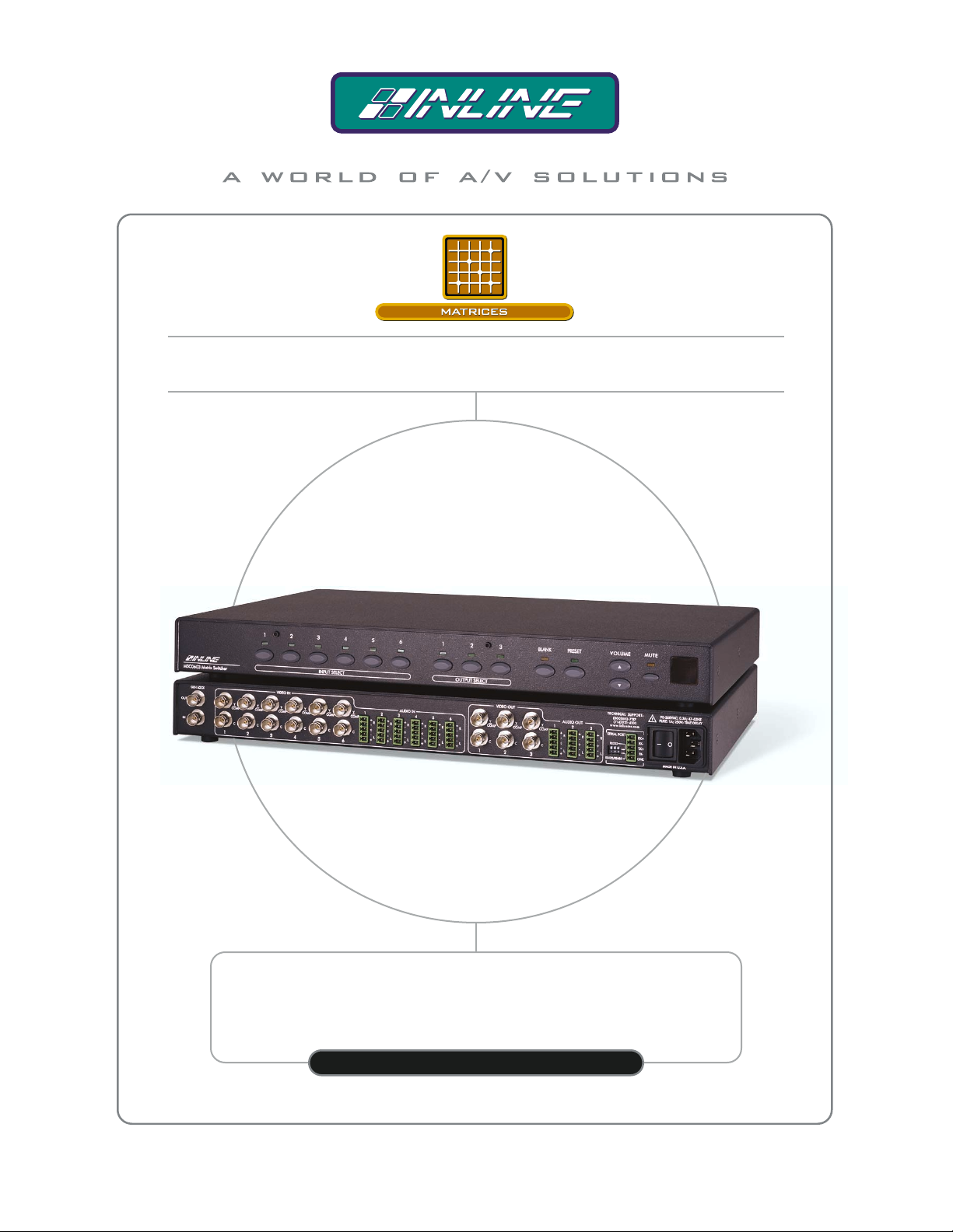
6 X 3 MATRIX SWITCHER
FOR COMPOSITE VIDEO / S-VIDEO AND STEREO AUDIO
MSC0603
OPERATION MANUAL
Page 2

Installation and Safety Instructions
For Models without a Power Switch:
The socket outlet shall be installed near the equipment and shall be accessible.
For all Models:
No serviceable parts inside the unit. Refer service to a qualified technician.
For Models with Internal or External Fuses:
For continued protection against fire hazard, replace only with same type and rating of fuse.
Instructions d’installation et de sécurité
Pour les modèles sans interrupteur de courant:
La prise de courant d’alimentation sera installé près de l’équipement et sera accessible.
Pour tout les modèles:
Pas de composants à entretenir à l’intérieur. Confiez toute réparation à un technicien qualifié.
Pour les modèles équipés de fusibles internes ou externes:
Afin d’éviter tout danger d’incendie, ne remplacer qu’avec le même type et la même valeur de fusible.
Installations- und Sicherheitshinweise
Für Geräte ohne Netzschalter:
Die Netzsteckdose soll in der Nähe des Gerätes installiert und frei zugänglich sein.
Für alle Geräte:
Keine Wartung innerhalb des Gerätes notwendig. Reparaturen nur durch einen Fachmann!
Für Geräte mit interner oder externer Sicherung:
Für dauernden Schutz gegen Feuergefahr darf die Sicherung nur gegen eine andere gleichen Typs und gleicher Nennleistung
ausgewechselt werden.
Instalacion E Instrucciones de Seguridad
Modelos Sin Interruptor:
Para Todos Los Modelos:
Modelos con Fusibles Internos o Externos:
La conexión debe ser instalada cerca del equipo y debe ser accesible.
Dentro de la unidad , no hay partes para reparar. Llame un tecnico calificado.
Para prevenir un incendio, reemplace solo con el mismo tipo de fusible.
CE COMPLIANCE
All products exported to Europe by Inline, Inc. after January 1, 1997 have been tested and found to
comply with EU Council Directive 89/336/EEC. These devices conform to the following
standards:
EN50081-1 (1991), EN55022 (1987)
EN50082-1 (1992 and 1994), EN60950-92
Shielded interconnect cables must be employed with this equipment to ensure compliance with
the pertinent Electromagnetic Interference (EMI) and Electromagnetic Compatibility (EMC)
standards governing this device.
FCC COMPLIANCE
This device has been tested and found to comply with the limits for a Class A digital device,
pursuant to Part 15 of the FCC rules. These limits are designed to provide against harmful
interference when equipment is operated in a commercial environment. This equipment generates,
uses and can radiate radio frequency energy and, if not installed and used in accordance with th e
instruction manual, may cause harmful interference to radio communications. Operation of
equipment in a residential area is likely to cause harmful interference, in which case the user will be
required to correct the interference at their own expense.
Page 3

Table of Contents
Table of Contents ..........................................................................................................................1
Product Overview .........................................................................................................................2
Description........................................................................................................................2
Product Features................................................................................................................2
Compatibility.................................................................................................................................3
Video Inputs ......................................................................................................................3
Genlock Input/Output........................................................................................................3
Audio Inputs......................................................................................................................3
Analog Audio Signals.........................................................................................3
Video Outputs...................................................................................................................3
Audio Outputs...................................................................................................................3
Analog Audio Signals.........................................................................................3
Installation.....................................................................................................................................4
Operation.......................................................................................................................................7
Front Panel Controls ......................................................................................................... 7
Switching - Connecting Inputs & Outputs (Front Panel)...................................................7
To make a connection between an input and an output:......................................7
To select a different input:..................................................................................7
To blank the output:............................................................................................7
To configure a new input/output patch:..............................................................8
To store a preset:.................................................................................................8
To recall a stored preset:.....................................................................................8
Audio ................................................................................................................................8
Adjusting input audio volume level ....................................................................9
To mute and/or restore audio output:..................................................................9
Serial Ports........................................................................................................................9
RS-232/RS-422/RS-485 Connections ...............................................................................9
Dipswitch settings...........................................................................................................10
To create a preset:.............................................................................................10
Power-on Settings...........................................................................................................10
Reset to Factory Default..................................................................................................10
Remote Operation.......................................................................................................................11
RS-232 Control...............................................................................................................11
Communication Protocol:.................................................................................11
Protocol Structure.............................................................................................11
Using the CTL120-2 Remote Control.............................................................................12
To configure a new input/output patch using the CTL120-2 remote control: ...12
Serial Commands........................................................................................................................13
Addressing Commands ...................................................................................................13
Set-up Commands...........................................................................................................14
Level Commands............................................................................................................14
Switching Commands.....................................................................................................15
Volume Commands.........................................................................................................15
Preset Commands............................................................................................................17
Specifications...............................................................................................................................19
Warranty......................................................................................................................................22
2002 - INLINE, INC. MSC0603 OPERATION MANUAL - v1.0 5/7/02
Page 4

2
Product Overview
Description
MSC0603 is a compact 6 x 3 composite video/S-Video and Stereo Audio Matrix switcher
featuring composite video/S-Video stereo audio matrix switching, 100 MHz video bandwidth,
and one switching mode. It is ideal for permanent installations, rentals, complex staging
operations, and any other display system requiring a high performance, economical composite
video/S-Video stereo audio matrix switcher.
MSC0603 Model Inputs/Outputs Video Matrix
(1 BNC)
MSC0603-1 6 x 3
MSC0603-2 6 x 3
MSC0603-3 6 x 3
MSC0603-4 6 x 3
Product Features
• Video Performance — Provides 100 MHz video bandwidth
S-Video Matrix
(2 BNCs)
Stereo Audio
Matrix
• Integrated Labeling — Matrix faceplates include attachment posts to hold optional
nameplates that the user can engrave to identify inputs, outputs, or preset functions
• IR Remote Control Capability — Enables user to select inputs/outputs and adjust
volume using optional CTL 120 IR Remote Control
• Robust RS-232/RS-422/RS-485 Serial Control Capability — Provides connection to a
third party control system
• New Serial Control Protocol — Offers fast, easy programming and powerful control
options, such as individual unit addresses
• Audio Inputs — Compatible with balanced or unbalanced stereo audio signals
• Audio Outputs — Can be wired to output balanced or unbalanced stereo audio
• Individual Audio Input Trim Levels — Units can store a unique input level for each
input
• Master Volume Control and Mute — For Each Output
• 32 Configuration Memories — Store and recall input/output configurations and audio
levels
• Genlock Input — Matrix offers vertical interval switching for glitch-free transitions
when used with synchronous video sources
MSC0603 OPERATION MANUAL - v1.0 5/7/02 2002 - INLINE, INC.
Page 5

3
Compatibility
Video Inputs
The MSC0603 matrix switcher provides six female BNC inputs and accepts composite video and
S-Video signals on all six inputs.
Genlock Input/Output
The MSC0603 provides one BNC input and one BNC output for genlock to allow switching to
occur during the vertical interval.
Audio Inputs
Analog Audio Signals
Inputs 1-6 include 5-pin captive screw terminals for analog audio input. All eight analog stereo
audio inputs are compatible with unbalanced and balanced line level signals from a VCR, DVD
player, computer audio card, or any other audio device that delivers a stereo line level signal.
Video Outputs
The MSC0603 provides three BNC outputs.
Audio Outputs
Analog Audio Signals
The analog stereo audio output provides a balanced or unbalanced line level output signal (see
page 4 for output wiring diagram). This output can drive any line level compatible audio unit, or
a local device such as powered speakers. The output level is adjustable using the volume control.
2002 - INLINE, INC. MSC0603 OPERATION MANUAL - v1.0 5/7/02
Page 6
4
Installation
Below are instructions for installing the MSC0603 Matrix Switcher. An application diagram
showing typical connections is on page 5.
Note:
1. Place/install the MSC0603 at the desired location. Seat the unit on a flat surface or
securely install it in a standard 19" equipment rack using the MTR102 rack ears
(provided). The MSC0603 is exactly 1U high without
be located in the space directly below the matrix switcher, you must remove the rubber
feet on the bottom of the unit before mounting it in the equipment rack.
2. Connect the output display devices (monitors, data projectors, etc.) to the matrix
switcher BNC connector outputs. The MSC0603 features three BNC composite video
outputs and three S-Video BNC S-Video outputs for easy connections to display devices.
You can connect display devices with a BNC input directly to the MSC0603 BNC output
ports using standard BNC cables. INLINE’s IN8000 Series flexible BNC cables offer
exceptional performance and are available in a variety of lengths.
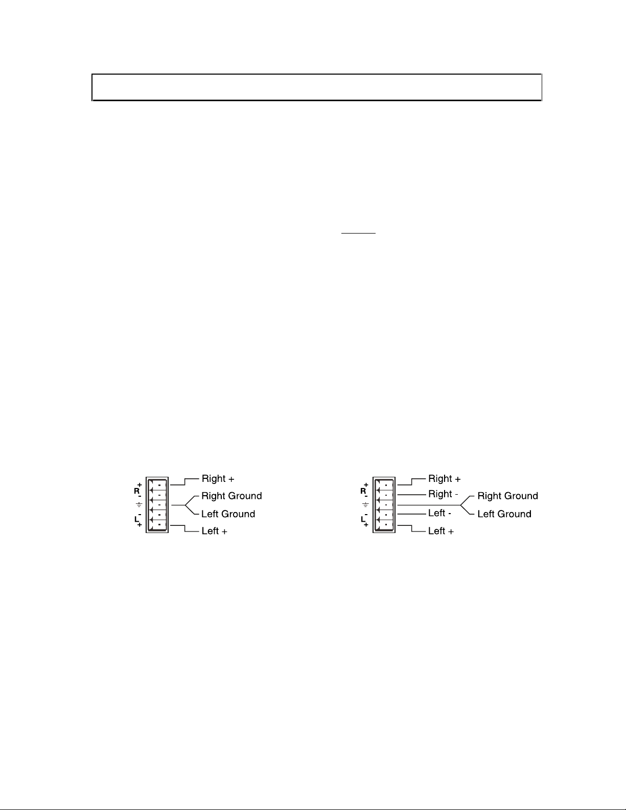
3. Connect the MSC0603 analog stereo audio output (5-pin captive screw terminal) to the
audio system’s line level input (mixer, amplifier, powered speakers, etc.). The output can
be set for balanced or unbalanced output signal as required by wiring the output
appropriately (see wiring diagram below). The analog audio output connector will
accept stranded or solid cables from 20 - 26 AWG.
For Unbalanced Stereo Audio Output: For Balanced Stereo Audio Output:
Prior to initiating the installation procedure, ensure that there is
no power supply cord connected to the unit.
the feet. If other equipment will
4. Connect the input video sources to the matrix switcher’s BNC connector inputs.
5. Connect the audio sources to the audio inputs. All five inputs accept balanced or
unbalanced stereo audio signals. Connect the audio signals to the 5-pin captive screw
connectors.
6. If desired, connect a control system, computer, or other serial command source to the
RS-232 remote connector. Cable the control system or computer serial port to the serial
port based on the type of connection described on page 9.
7. Connect power to the Matrix switcher, display devices, and serial and audio equipment
as applicable. To connect power to the switcher, attach the power cord to the connector
on the rear of the set. A standard IEC power cord comes with the unit. Plug it into a 100
– 40 VAC, 50Hz or 60Hz power source.
MSC0603 OPERATION MANUAL - v1.0 5/7/02 2002 - INLINE, INC.
Page 7
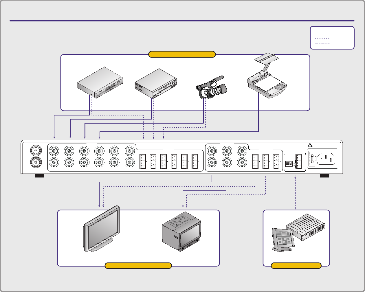
APPLICATION DIAGRAM
MSC0603 COMPOSITE/S-VIDEO MATRIX SWITCHER
Video Camera Document CameraVCRDVD
Plasma Display Monitor Control System
input devices
output devices control
= Video
= Audio
= Control
C
Y
COMP
IN
GEN LOCK
OUT
1
C
2
COMP
Y
COMP
34
C
COMP
VIDEO IN
Y
5
C
6
C
Y
Y
COMP
+
-
C
LL
+
-
+
Y
COMP
12
RR
+
-
+
LL
-++
AUDIO IN
+
-
3R4
R
+-+
-
5
C
Y
COMP
LL
-
+
1
R6R
+
-
23
C
COMP
VIDEO OUT
Y
TX+
RX-
RX+
GND
TX-
C
+
L
+
L
AUDIO OUT
COMP
Y
-
+
1R2
-
+
R
RS232
RS422/RS485
L
+
-
R
-
+
3
SERIAL PORT
FUSE: 1A; 250V; TIME DELAY
90-260VAC; 0.3A; 47-63HZ
!
MADE IN U.S.A.
TEC
H
N
IC
A
L SU
PPO
RT
(8
0
0
) 8
8
2
-7
1
1
7
(7
1
4
) 9
2
1
-4
1
0
0
w
.w
.w
. inlin
einc.com
Page 8
MSC0603 COMPOSITE/S-VIDEO
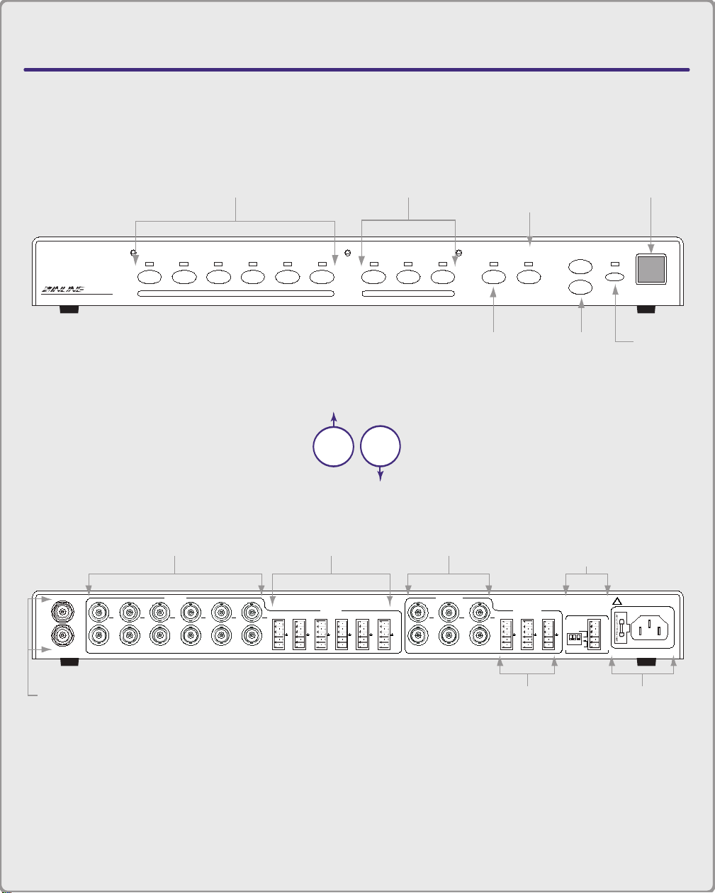
MATRIX SWITCHER
CONNECTORS & CONTROLS
Rear
View
Front
View
2345612 BLANK PRESET MUTEVOLUME1 3
INPUT SELECT OUTPUT SELECT
MSV0603 A/V Matrix Switcher
C
Y
COMP
IN
GEN LOCK
OUT
1C 2
COMP
Y
COMP
34
C
COMP
VIDEO IN
Y
5C 6
C
Y
Y
COMP
+
-
C
LL
+
-
+
Y
COMP
12
RR
+
-
+
LL
-++
AUDIO IN
+
-
3R4
R
+-+
-
5
C
Y
COMP
LL
+
1
R6R
+
-
23
C
COMP
VIDEO OUT
Y
TX+
RX-
RX+
GND
TX-
C
+
L
+
L
AUDIO OUT
COMP
Y
-
+
1R2
-
+
R
RS232
RS422/RS485
L
+
-
R
-
+
3
SERIAL PORT
FUSE: 1A; 250V; TIME DELAY
90-260VAC; 0.3A; 47-63HZ
!
MADE IN U.S.A.
TECHNICAL SUPPORT
(800) 882-7117
(714) 921-4100
w.w.w. inlineinc.com
Input Buttons 1-6
Output Buttons 1-3
Blank
Button
Preset
Button
Volume
Buttons
Mute
Button
IR Window
Audio Outputs 1-3
Audio Inputs 1-6
Video Inputs 1-6
Video Outputs 1-3 RS232/422/485
Serial Port
A/C Power
Input
Genlock
Input/Output
Page 9

Operation
Front Panel Controls
Input Select 1 - 6: Selects the designated input
Output Select 1 - 3: Selects the designated output
Preset: Stores or recalls a preset configuration, which includes all input/output patches and
volume levels
Blank: Blanks the currently selected output
Mute: Silences audio for the selected output
Volume: Increases or decreases volume level of the selected audio output
IR Window: Receives IR commands from optional CTL 120 IR remote control
Switching - Connecting Inputs & Outputs (Front Panel)
To make a connection between an input and an output:
1. Select the output.
2. Assign it an input.
3. Press the button of the output you want to change.
Result: The LED above the output button glows (only one output can be selected at a
time). The LED of the input currently sent to that output also glows.
To select a different input:
Press the desired input button.
To blank the output:
Press the Blank button.
Once you select an output, you can change the input as many times as desired.
7
2002 - INLINE, INC. MSC0603 OPERATION MANUAL - v1.0 5/7/02
Page 10

8
To configure a new input/output patch:
1. Press the desired output select button.
2. Press the input select button you want to connect to the output.
Example: To patch input 4 to output 2, press the Output 2 button followed by the Input 4
button.
To store a preset:
1. Configure all necessary input/output patches.
2. Adjust audio volume levels.
3. Press and hold the Preset button for 5 seconds.
4. Press the input or output button you want to use to designate as the preset number for
that configuration.
To recall a stored preset:
Press the Preset button, followed by an input or output button.
Switching and defining multiple groups is only feasible if you control the unit via RS-232.
Audio
The MSC0603 routes stereo audio along with the video. The audio for the selected input routes
to the selected output.
The MSC0603 has Volume Up and Down buttons as well as a Mute button. These buttons
function as follows:
Volume Up/Down - The Volume Up button increases the output volume; the Volume Down
button decreases it. The volume is increased/decreased for the currently selected output. The
output button’s LED flashes to indicate a change. The LED stops flashing upon reaching the
maximum or minimum level.
To adjust
output audio volume level:
Press the Volume buttons on the front panel to raise or lower the volume of an output.
MSC0603 OPERATION MANUAL - v1.0 5/7/02 2002 - INLINE, INC.
Page 11

9
Adjusting input audio volume level
Adjusting the volume allows users to equalize the audio levels of the various inputs. This is
important so the volume level does not increase/decrease dramatically when switching between
inputs.
1. Press and hold the Mute button.
2. While still pressing the Mute button, press the Input button that corresponds to the input
device for which you want to adjust the volume.
3. Press the Volume buttons to raise or lower the volume of the input device.
The Mute Button silences the audio signal. When the audio is muted (no audio) the LED glows.
The audio remains muted until you press the button again.
To mute and/or restore audio output:
Press the Mute button to alternately silence/restore audio output.
Serial Ports
The MSC0603 utilizes a 5-pin captive screw terminal block. The pin configurations are as
follows:
RS-232/RS-422/RS-485 Connections
RS-232 Connection Diagram: Full Duplex RS-422/485 Connection Diagram:
Half Duplex RS-485 Connection Diagram:
2002 - INLINE, INC. MSC0603 OPERATION MANUAL - v1.0 5/7/02
Page 12
10
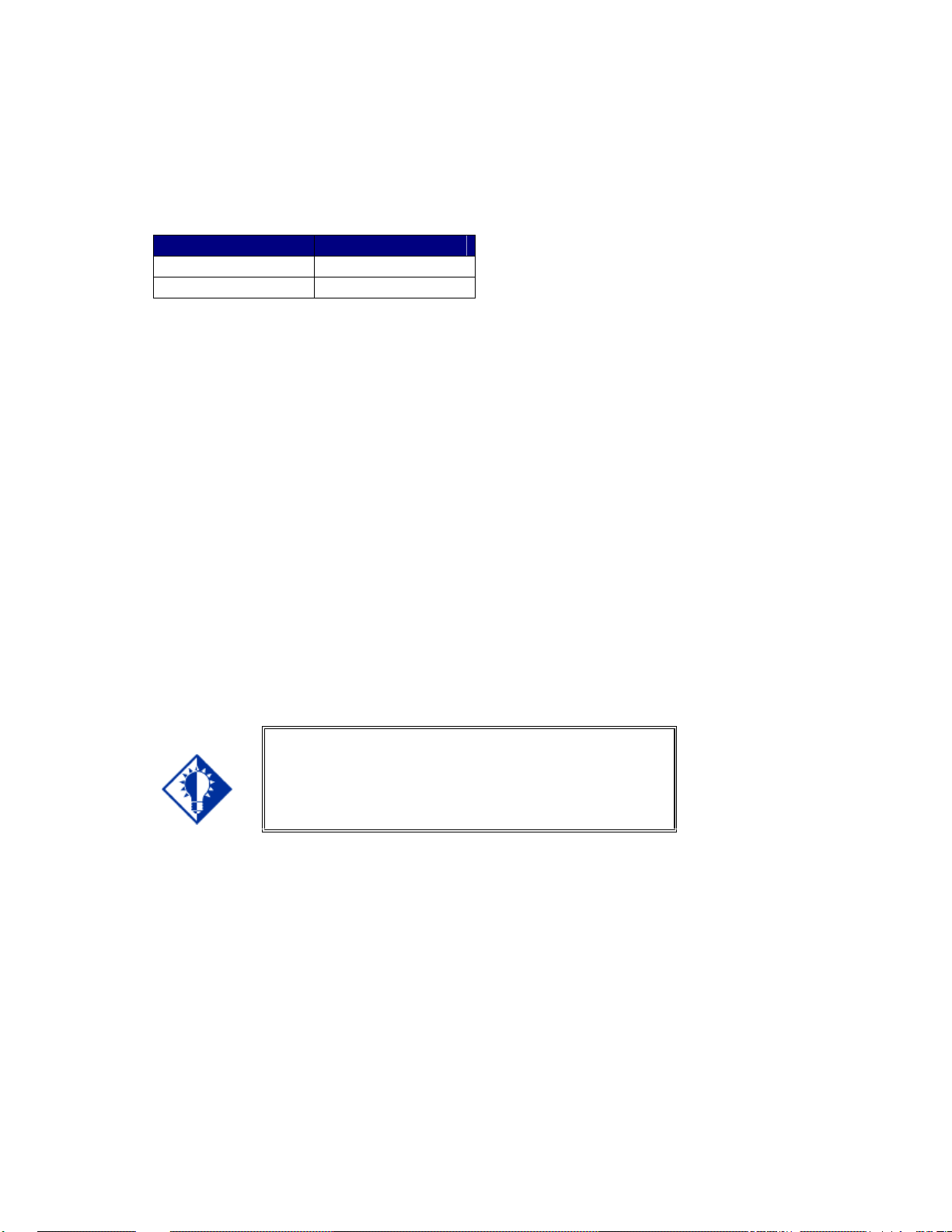
Dipswitch settings
Dipswitch settings change according to the standard used. Higher standards require a different
signal type. Dipswitches make subtle adjustments to that signal type. Configure the dipswitch
settings according to the following table.
Serial Format Dipswitch Settings
RS-232* 123 OFF
RS-422/RS-485 123 ON
*Factory default
Creating Presets
Once you create a switch or patch through the Output-Input method, you can assign it a Preset
number. This is a valuable, timesaving feature and allows unskilled operators the ability to
duplicate complex patches without having to actually configure the patch.
To create a preset:
1. Create the desired configuration of input/output connections.
2. Press the Preset button.
3. Press any one of the Input or Output select buttons to pick a storage location for this
preset.
4. Be sure to label or notate each Preset you make.
5. To recall a preset, press the Preset button, followed by the input/output button where the
preset was stored.
Key Concept
When you turn the MSC0603 on, it uses setup #1 as the
default, and this cannot change. If you plan on turning
off the MSC0603, make certain to store the initial
settings in setup #1.
Power-on Settings
To power the MSC0603 up, simply plug the unit it the outlet. There is no power on/off switch.
Reset to Factory Default
Soft Reset - To restore I/O configurations, volume levels, and the serial set up to the default
factory setting, press the 1 and 5 input buttons.
Hard Reset - To restore all parameters, including presets, to the default factory setting, use the
[DFLTx] command.
MSC0603 OPERATION MANUAL - v1.0 5/7/02 2002 - INLINE, INC.
Page 13

Remote Operation
RS-232 Control
The MSC0603 RS-232/RS-422/RS-485 serial control port accepts serial commands from a
control system, computer serial port, or any other device capable of sending out serial ASCII
commands at compatible baud rates. A complete listing of RS-232/RS-422/RS-485 codes is
included below.
Communication Protocol:
• 8 data bits
• 1 stop bit
• No parity check
• 9600 baud (factory default setting)
Protocol Structure
All commands sent to the unit must contain a leading character, the actual command, and an
ending character. The MSC0603 can accept multiple commands, storing them in a buffer. It
immediately executes each command in the order it was issued.
The MSC0603 recognizes [ and ] as leading and ending characters, also called Command
Codes. The factory default for the Command Code is [ ]. The Command code can be changed
via RS-232. Some sample command codes follow. For example:
This part of the command
string...
[
ADDRxx
]
This command string... Means:
[ADDRxx]
Represents:
The leading character
The actual command.
The ending character
Assign an address to the unit, 01 to 98,
where xx = 01-98.
11
2002 - INLINE, INC. MSC0603 OPERATION MANUAL - v1.0 5/7/02
Page 14

12
Using the CTL120-2 Remote Control
CTL120-2 IR Remote Control sends infrared commands to the CTL101. The CTL101 will
convert these IR signals to serial commands so you can control functions on the MSC0603
matrix switcher. A diagram outlining the location of each button is on page 18.
To use the CTL120-2 remote, press the MATRIX button. The remote is now in matrix switcher
mode.
To configure a new input/output patch using the CTL120-2 remote control:
1. Press the remote control button that corresponds to the desired output select button.
2. Press the remote control button that corresponds to the desired input select button you
want to connect to the output.
Note: The Blank button on the remote control does not work to blank the
currently selected output.
MSC0603 OPERATION MANUAL - v1.0 5/7/02 2002 - INLINE, INC.
Page 15

13
Serial Commands
Addressing Commands
If the switcher is being used in RS-232 mode (no other devices connected in parallel) there is no
need to assign an address for this unit. If you are using multiple Inline products connected in
parallel to a single serial port using RS-422 or RS-485 communications, you will need to assign
an address for each unit.
The factory default for the unit is no address. The address for the unit must be between 01 and
98. Address 00 is a broadcast address and all units on the buss will perform the action
commanded; however, they will not issue any responses.
To open communications to an addressed device, you must send a [CCxx] command. All other
devices on the buss will ignore commands until addressed.
COMMAND DESCRIPTION
[ADDRxx]
[ADDR@]
[ADDR?]
[CCxx]
Assigns an address to the unit, 01 to 98. Address 99 is reserved for future
products.
• Where xx = 01 - 98
Removes an address from the unit. This is the factory default, and is the
typical way to use the switcher when in the RS-232 mode
Query unit for a pre-assigned address.
Connects controller to the addressed unit. 00 is a broadcast address thus all
connected devices will perform commands. This command is to be used in
conjunction with the [ADDRxx] command string.
• Where
o xx = 01 - 98
o Note: This command string is case sensitive.
2002 - INLINE, INC. MSC0603 OPERATION MANUAL - v1.0 5/7/02
Page 16

14
Set-up Commands
These commands are for configuring the switcher, and you only need to send them once. If using
a third party control system, you should place most commands in this section in the start-up
section of the program.
COMMAND DESCRIPTION
[ARC]
[CPx@]
Request for model and version information.
Re-sets the communications port to default of 9600, 8, N and 1.
• Where x = 1
[CPx?]
Query communications port for current settings.
• Where x = 1
[CPxbpsfd]
Configures the communications port for baud rate, parity, stop bits, flow
control and duplex.
• Where
o x = 1
o b = 0 for 1200, 1 for 2400, 2 for 4800, 3 for 9600, 4 for
19200, 5 for 38400
o p = 0 for no parity, 1 for odd parity, 2 for even parity
o s = 0 for 1 stop bit, 1 for 2 stop bits
o f = 0 to disable flow control, 1 to enable flow control
o d = 0 for full duplex and 1 for half duplex
[DFLTx]
Performs a factory reset. The partial reset will default I/O configurations,
volume levels and serial set-up but does not reset presets. A full reset will
reset all parameters including presets.
• Where x = 0 for partial reset, 1 for full reset
[FPx]
Enable/disable front panel control and request current status.
• Where
o x = 0 to disable, 1 to enable
o x = ? to request current state
o x = (left blank) to toggle current state
[RESx]
Enable/disable serial responses from switcher.
• Where x = 0 to disable, 1 to enable
[VISx]
Enable/Disable Vertical Interval Switching. Requires sources to be
Genlocked. Contact Inline Inc. For specific application support.
• Where x = 0 to disable, 1 to enable, ? to query
Level Commands
There are three predefined switching levels. Levels consist of combinations of Video (RGB),
Sync (HV) and Audio boards (A). For commands that use level designators see Switching
Commands below.
Default levels include:
• Level 1 - RGBHVA
• Level 2 - RGBHV
• Level 3 - Audio only
MSC0603 OPERATION MANUAL - v1.0 5/7/02 2002 - INLINE, INC.
Page 17

Switching Commands
These commands can only initiate a one-input-to-one-output switch.
COMMAND DESCRIPTION
[MSxOooIii]
Executes a matrix switch of an input to an output for a
specific level.
• Where
o x = 1 - 3 for specific level
o oo = 01 - 03 for output
o ii = 00 - 06 for input (00 = blank)
[MSx?]
[BLANKoo]
Returns the current connections for Level x
Blanks a specific output.
• Where oo = 01 - 03 for output
Volume Commands
Use these commands to control volume levels for both inputs and outputs. Typically, adjust
input volume levels to minimize drastic changes in volume when performing switches.
COMMAND DESCRIPTION
[MUTEoox]
[MUTE]
[VOLoox]
[VOLooxxx]
[VOLLoox]
Used to mute/un-mute a specific output and request current status.
• Where
o oo = 01 - 03 for output
o x = 0 to disable mute, 1 to enable mute
o x = ? to request current state
o x = (left blank) to toggle current state
Toggle mute/un-mute all outputs.
Sets volume level for a specific output.
• Where
o oo = 01 - 03 for output
o x = + (plus sign) to increment output volume
o x = - (minus sign) to decrement output volume
o x = @ to return output volume to factory default
o x = ? to request current volume level
Sets volume level for a specific output.
• Where
o oo = 01 - 03 for output
o xxx = -550 - 090
o Note: 090 equals max (9 db gain), 000 equals factory
default (unity gain), -550 equals minimum (-55db)
Sets left channel volume level for a specific output.
• Where
o oo = 01 - 03 for output
o x = + (plus sign) to increment output volume
o x = - (minus sign) to decrement output volume
o x = @ to return output volume to factory default
o x =? to request current volume level
15
2002 - INLINE, INC. MSC0603 OPERATION MANUAL - v1.0 5/7/02
Page 18

16
COMMAND DESCRIPTION
[VOLLooxxx]
Sets left channel volume level for a specific output.
• Where
o oo = 01 - 03 for output
o xxx = -550 - 090
o Note: 090 equals max (9 db gain), 000 equals factory
[VOLRoox]
Sets right channel volume level for a specific output.
• Where
o oo = 01 - 03 for output
o x = + (plus sign) to increment output volume
o x = - (minus sign)to decrement output volume
o x = @ to return output volume to factory default
o x = ? to request current volume level
[VOLRooxxx]
Sets right channel volume level for a specific output.
• Where
o oo = 01 - 03 for output
o xxx = -550 - 090
o Note: 090 equals max (9 db gain), 000 equals factory
[VOLx]
Sets volume level for all outputs.
• Where
o x = + (plus sign) to increment output volume
o x = - (minus sign) to decrement output volume
o x = @ to return output volume to factory default
o x = ? to request current volume level
[VOLRMPoox]
Starts volume ramp of a specific output.
• Where
o oo = 01 - 03 for output
o x = + (plus sign) for volume ramp up
o x = - (minus sign) for volume ramp down
[VOLSTOP]
[VINiix]
Stop volume ramp function.
Sets input volume level for a specific input.
• Where
o ii = 01 - 06 for input
o x = + (plus sign) to increment input volume
o x = - (minus sign) to decrement input volume
o x = @ to return input volume to factory default
o x = ? to request current volume level
[VINiixxx]
Sets input volume level for a specific input.
• Where
o oo = 01 - 06 for input
o xxx = -640 - 000
o Note: 000 equals max (factory default), -640 equals
default (unity gain), -550 equals minimum (-55db)
default (unity gain), -550 equals minimum (-55db)
minimum
MSC0603 OPERATION MANUAL - v1.0 5/7/02 2002 - INLINE, INC.
Page 19

17
COMMAND DESCRIPTION
[VINx]
Sets input volume level for all inputs.
• Where
o x = + (plus sign) to increment input volume
o x = - (minus sign) to decrement input volume
o x = @ to return input volume to factory default
o x = ? to request current volume level
Preset Commands
The MSC0603 and MSV0804 have the ability to store and recall common configurations. Both
units offer 32 presets available via serial control. The MSC0603 has 7 presets available via the
front panel while the MSX0804 has 12 presets available via the front panel.
COMMAND DESCRIPTION
[PSVxxx]
[PRCxxx]
Save current configuration to preset memory.
• Where xx = 01 - 32
Recall stores configuration from preset memory.
• Where xx = 01 - 32
2002 - INLINE, INC. MSC0603 OPERATION MANUAL - v1.0 5/7/02
Page 20

CONNECTORS & CONTROLS
MSV0502 / MSV0804 / MSC0603 Matrix Switchers
CTL120-2 REMOTE CONTROL
1st BUTTON TO PRESS
CH VOL
ENTERMENU
BLANK MUTE
FREEZE
INPUT RECALL
ENTER
ENTPIP
AUDIO
POWER
123
45
897
0
6
S
MATRIXSWITCHER
VIDEO
SCALER
+
–
+
–
MENU OK
MATRIX
CTL120-2 COMMAND EXAMPLES FOR MSV0502/MSV0804/MSC0603 MATRIX SWITCHERS
COMMAND EXAMPLES
function:
Configure an input/output patch.
steps:
Press the numeric button that corresponds to the desired
output select button.
Press the numeric button that corresponds to the desired
input select button.
function:
Increase the audio level.
steps:
Press the VOL + button once to increase the volume slightly.
Press and hold VOL + to continuously increase the volume.
function:
Mute the audio signal.
steps:
Press the MUTE button to engage mute.
Press MUTE again to return to previous volume.
Numeric Buttons
Select desired output,
followed by the desired input
Enter Button
Press to make a menu selection or to
execute a new setting when using
on-screen menus
Vol + Button
Increases audio level
Vol – Button
Decreases audio level
Controls
all outputs
simultaneously
Mute Button
Mutes audio signals
Matrix Button
Press this button first to set
the CTL120 to control
MSV0502 / MSV0804
matrix switchers
IMPORTANT: You must press the MATRIX button ( ) once to set the CTL120 remote to control
MSV0502/MSV0804/MSC0603 matrix switchers.
MATRIX
Page 21

Specifications
MSC0603 Specifications
Video
Gain Unity (1.0 V/V)
Bandwidth 100 MHz @ -3dB with .7V p-p input signal, fully loaded
0 - 10 MHz: < +0.1 dB to -0.1 dB
0 - 30 MHz: < +0.3 dB to -0.3 dB
Crosstalk 1 MHz: -67.2dB (worst) to -74.3dB (best)
10 MHz: -51.2dB (worst) to -70.2dB (best)
Video Input
Number/Connectors MSC0603-1/-2: (6) BNC Female for Composite Video
MSC0603-3/-4: (6) Pairs of BNC Female for Composite
Nominal Input Level Composite Video: 1.0V
S-Video - Chroma: 0.3V
S-Video - Luma: 1.0V
Maximum Input Level 1.8 Vp (including any DC Offset)
Impedance 75
Input Return Loss -46.0 dB @ 5 MHz
Video Output
Number/Connectors/Signal Type MSC0603-1/-2: (3) BNC Female for Composite Video
MSC0603-3/-4: (3) Pairs of BNC Female for
Impedance 75
Output Return Loss -46.0 dB @ 5 MHz
Genlock
Input Connector (1) BNC female for External Sync (Genlock)
Signal Level 0.3 - 0.4V p-p
Output Connector (1) BNC female for Genlock loop out
Video or S-Video
Composite Video or S-Video
19
2002 - INLINE, INC. MSC0603 OPERATION MANUAL - v1.0 5/7/02
Page 22

20
MSC0603 Specifications, continued
Audio
Frequency Response 10 Hz to 175 KHz - 3dB
20 Hz to 20 KHz ± 0.05dB
THD+Noise 0.0038% (1.0Vp-p @ 1 KHz)
S/N Ratio 87.0 dB
Output Gain Adjustment +9.5 dB to -54.5 dB
Crosstalk -95 dB (1.0Vp-p @ 1 KHz)
Stereo Separation -95 dB (1.0Vp-p @ 1 KHz)
Audio Input
Number/Connectors/Signal Type (6) 5-Pin Captive Screw Terminal for Balanced/Unbalanced
Stereo Audio
Impedance 20
Maximum Input Level: +16 dBU
Input Gain Adjustment 0dB to - 55dB
Audio Output
Number/Connectors/Signal Type (3) 5-Pin Captive Screw Terminal for Balanced/Unbalanced
Stereo Audio
Impedance 50 8QEDODQFHG%DODQFHG
Maximum Output Level +22dBU (High Z)/+16dBm (600
Gain Error ± 0.1dB (channel to channel)
Control
Connector 5-Pin Captive Screw Terminal
Serial Protocol RS-232/RS-422/RS-485
Baud Rate 1,200 to 38,400 bps
General
Power Supply 90-260VAC; 47-63 Hz
Shipping Weight 9.6 lbs./4.4 kg
Product Weight 5.9 lbs./2.7 kg
Dimensions 1.78" x 17" x 11.35"/4.5cm x 43.2cm x 28.8cm
MTBF 35,000 Hours
Storage Temperature/Humidity -40° to 158° (-40° to 70° C)/10% to 90% non-condensing
Ambient Operating
32° to 113° (0° to 45° C)/10% to 90% non-condensing
Temperature/Humidity
Regulatory Approvals UL1950
CAN/CSA-22.2 No.950
Third Edition CE: EN55022 (1987)
EN50081-1 (1991)
EN50082-1 (1992 and 1994)
EN60950-92
Included Accessories
IN9123B Rack Mounting Ears
IN9339 Inline Adjustment Tool
ICS100 Inline Control Software
MSC0603 OPERATION MANUAL - v1.0 5/7/02 2002 - INLINE, INC.
Page 23

MSC0603 VGA MATRIX SWITCHER
PRODUCT DIMENSIONS
11.35"
right side view
17.00"
11.35"
1.99"
0.21"
MSV0603 A/V Matrix Switcher
top view
17.03"
2 3 4 5 6 1 2 BLANK PRESET MUTEVOLUME1 3
1.78"
INPUT SELECT OUTPUT SELECT
front view
1.99"
0.21"
17.03"
T
R
O
PP
U
S
L
A
C
I
N
H
C
GEN LOCK
OUT
IN
Y
COMP
1C 2
Y
COMP
C
VIDEO IN
Y
COMP
C
3 4
Y Y
COMP
COMP
C
5C 6
+
R R
-
L L
+
AUDIO IN
3R4
+
-
L L
+
+-+
R
-+-
5
+
R6R
-
-
-
L L
+
+
+
-
-
+
Y
1 2
COMP
C
VIDEO OUT
Y
Y
COMP
COMP
C
C
1
2 3
AUDIO OUT
Y
1R2
COMP
+
-
C
L
+
TE
800)
(
(714)
i
w.
w.
.
w
3
SERIAL PORT
+
+
R
R
-
-
RS232
-
-
L
L
+
+
RS422/RS485
882-71
921-4
n
90-260VAC; 0.3A; 47-63HZ
!
17
FUSE: 1A; 250V; TIME DELAY
100
m
co
c.
n
ei
n
li
RX+
RXTX+
TX-
GND
MADE IN U.S.A.
1.78"
back view
Page 24

22
Warranty
• INLINE warrants the equipment it manufactures to be free from defects in materials
and workmanship.
• If equipment fails because of such defects and INLINE is notified within three (3) years from
the date of shipment, INLINE will, at its option, repair or replace the equipment at its plant,
provided that the equipment has not been subjected to mechanical, electrical, or other abuse
or modifications.
• Equipment that fails under conditions other than those covered will be repaired at the current
price of parts and labor in effect at the time of repair. Such repairs are warranted for ninety
(90) days from the day of re-shipment to the Buyer.
• This warranty is in lieu of all other warranties expressed or implied, including without
limitation, any implied warranty or merchantability or fitness for any particular purpose, all
of which are expressly disclaimed.
The information in this manual has been carefully checked and is believed to be
accurate. However, INLINE, Inc. assumes no responsibility for any inaccuracies
that may be contained in this manual. In no event will INLINE, Inc. be liable for
direct, indirect, special, incidental, or consequential damages resulting from any
defect or omission in this manual, even if advised of the possibility of such
damages. The technical information contained herein regarding the MSC0603
features and specifications is subject to change without notice.
Windows is a registered trademark of Microsoft Corporation. All other
trademarks and registered trademarks are the property of their respective
companies.
All Rights Reserved © Copyright 2002 INLINE, Inc.
© INLINE, Inc. • 810 WEST TAFT • ORANGE, CA 92865
(800) 882-7117 • (714) 450-1800 • Fax: (714) 450-1850 • www.inlineinc.com
MSC0603 OPERATION MANUAL - v1.0 5/7/02 2002 - INLINE, INC.
 Loading...