

Page 1

MS9500GL HD FrEND Plus
MS9500 HD FrEND Plus
User Guide
Page 2

MS9500GL HD FrEND Plus User Guide
Copyright © 2009 Electrosonic, Inc.
All rights reserved
No part of this documentation may be reproduced or transmitted in any form or by any means, electronic or mechanical, including photocopying and
recording, without the prior written permission of Electrosonic, Inc.
The information in this documentation is supplied without warranty of any kind, either directly or indirectly, and is subject to change without prior
written notice. Electrosonic, Inc. its employees or appointed representatives will not be held responsible for any damages to software, hardware, or
data, howsoever arising as a direct or indirect result of the product(s) mentioned herein.
Issued by:
Electrosonic, Inc.
3320 North San Fernando Blvd
Burbank, CA 91504
Sales Support
Toll Free: 1.888.343.3602; Tel: 1.818.333.3602; Fax: 1.818.333.3679
products@Electrosonic.com
E-mail:
Technical Support
Toll Free: 1.888.832.4374
E-mail:
productsupport@electrosonic.com
Page 3

Preface
About This User Guide
This manual contains detailed information about your Electrosonic MS9500GL HD FrEND Plus.
We recommend that the user read ‘Chapter1: Introduction/Quick Reference Guide’ before setting up the Player.
This will give a basic understanding of how to use the MS9500GL.
The manual is comprised of the following chapters:
Chapter 1: Introduction/ Quick Reference Guide
Chapter 2: Player Configuration - LCD
Chapter 3: Player Configuration – HD player Application
Chapter 4: Linear Timecode (LTC)
Chapter 5: Genlock
Chapter 6: The Playlist Display
Chapter 7: Scenes
Chapter 8: Transport Status Display
Chapter 9: The Log/File Information Window
Chapter 10: Data Transfer
Chapter 11: Remote Control Configuration
Chapter 12: Remote Control Protocols
Chapter 13: Using the GPIO Interface
Appendix A: TCP/IP Communications
Appendix B: An Introduction to MPEG
Appendix C: Encoding Guidelines
Appendix D: Specifications
Glossary
Index
A full contents list appears after this preface.
Tested To Comply
with FCC Standards
HD FrEND
MS9500GL
1 Rev. 1.26
Page 4

CE Compliance
This Information Technology Equipment has been tested and found to comply with the following European
directives:
IEMC Directive 89/336/EEC amending directive 92/31/EEC & 93/68/EEC as per EN55024: 1998 EN55022: 1998
Class B
FCC Compliance
This equipment has been tested and found to comply with the limits for a Class B digital device, pursuant to part
15 of the FCC Rules. These limits are designed to provide reasonable protection against harmful interference in a
residential installation.
This equipment generates, uses and can radiate radio frequency energy and, if not installed and used in accordance
with the instructions, may cause harmful interference to radio communications. However, there is no guarantee
that interference will not occ ur in a particular installation. If this eq uipment does cause harmful interference to
radio or television reception, which can be determined by turning the equipment off and on, the user is encouraged
to try to correct the interference by one or more of the following measures:
Reorient or relocate the receiving antenna.
Increase the separation between the equipment and receiver.
Connect the equipment into an outlet on a circuit different from that to which the receiver is connected.
Consult the dealer or an experienced radio/TV technician for help.
Design Restrictions on High Risk Activities.
Products that use Microsoft XP Embedded software are not fault-tolerant and are not designed, manufactured or
intended for any use requiring fail-safe performance in which the failure of a Product could lead to death, serious
personal injury, severe physical or environmental damage (“High Risk Activities”). This includes the operation of
aircraft and nuclear facilities. The MS9500GL is not licensed for use in connection with any High Risk Activities.
Trademarks
ELECTROSONIC ®, MS ® and the ELECTROSONIC ® logo are registered trademarks of ELECTROSONIC Ltd.
ELECTROSONIC ®, ES ® and the ELECTROSONIC ® logo are registered trademarks of ELECTROSONIC Ltd.
WINDOWS ® is a registered trademark of MICROSOFT CORPORATION.
All other brand and product names are trademarks or registered trademarks of their respective holders.
2 Rev. 1.26
Page 5

Document History
VERSION DATE BY COMMENTS
1.0 12.18.06 SS Initial Release
1.1 01.22.07 IS/SS General updates; system diagram
1.2 03.15.07 SS/RH IR, Channel Properties
1.21 03.06.07 SS Differentiate unique 9500GL features from those of 9500
1.22 06.22.07 SS Add Timecode command protocols.
1.23 10.26.07 IGS Update Sync control guidelines based on MSTN104
1.24 03.03.08 KF/RM Update Default RS232 settings/ Added Command Reference
1.25 6.10.08 IGS/SJS Correct RGBs description in command reference. Command
caveat.
1.26 3.13.09 SS/IGS XP disclaimer. Fastseek revisions. Default Resolutions. FCC
text.
1 Rev. 1.26
Page 6

MS9500GL HD FrEND Plus
Table of Contents
Preface..................................................................................................... 1
About This User Guide....................................................................................................................................1
CE Compliance..............................................................................................................................................2
FCC Compliance........................................................................................................................................... 2
Design Restrictions on High Risk Activities................................................................................................... 2
Trademarks...................................................................................................................................................... 2
Document History........................................................................................................................................... 1
Table of Contents.................................................................................... 2
Chapter 1: Introduction/Quick Reference Guide ...........................8
Main Features .................................................................................................................................................8
Installation........................................................................................................................................................9
Rack Mounting...........................................................................................................................................9
Wall Mounting...........................................................................................................................................10
Front Panel.....................................................................................................................................................11
Front Panel Controls.................................................................................................................................11
Navigating the LCD ............................................................................................................................... ......11
Player Connections...................................................................................................................................... 12
MS9500GL Connector interface:...........................................................................................................12
MS9500 Connector Interface:................................................................................................................ 13
System Configuration...................................................................................................................................13
LCD: “Quick Start”........................................................................................................................................15
To play a Test File from the LCD interface:........................................................................................... 15
HD Player GUI................................................................................................................................................16
To play a Test File from the HD Player application: ............................................................................17
IR Remote (Hand-Held)...............................................................................................................................17
Chapter 2: Player Configuration - LCD........................................... 18
Playback........................................................................................................................................................18
Loop On/Off..............................................................................................................................................18
Play.............................................................................................................................................................19
Pause .........................................................................................................................................................19
Stop............................................................................................................................................................ 19
Screen On/Off..........................................................................................................................................19
Color bars..................................................................................................................................................19
Audio On/Off............................................................................................................................................ 19
Volume ......................................................................................................................................................19
Color BCS...................................................................................................................................................19
Schedule On/Off......................................................................................................................................20
Scenes............................................................................................................................................................20
Content: Local..............................................................................................................................................20
Files.............................................................................................................................................................20
Current Playlist.......................................................................................................................................... 20
Playlists.......................................................................................................................................................21
Schedules.................................................................................................................................................. 21
Content: Test................................................................................................................................................. 22
2 Rev. 1.26
Page 7

MS9500GL HD FrEND Plus
Communications...........................................................................................................................................22
Ethernet......................................................................................................................................................22
RS232...........................................................................................................................................................22
System.............................................................................................................................................................23
Output........................................................................................................................................................23
Resolution...................................................................................................................................................23
Frame Rate................................................................................................................................................23
Audio............................................................................................................................... ...........................23
Time/Date..................................................................................................................................................23
Computer name.......................................................................................................................................24
LCD Timeout..............................................................................................................................................24
Factory Defaults........................................................................................................................................24
Field Order .................................................................................................................................................24
Lock.................................................................................................................................................................24
Help.................................................................................................................................................................24
Chapter 3: Player Configuration - HD Application........................25
The Channel Properties dialog...................................................................................................................25
Set the channel to loop at startup.........................................................................................................26
Set the channel to start playin g at startup...........................................................................................26
Video on at startup ..................................................................................................................................26
Audio on at startup ..................................................................................................................................26
Output black when file completes........................................................................................................26
Enable AV Sync.........................................................................................................................................26
Enable Scheduler......................................................................................................................................27
Base Channel Number ............................................................................................................................27
Audio Output Format...............................................................................................................................27
Output Standard.......................................................................................................................................27
Genlock......................................................................................................................................................28
BCS – Brightness-Contrast—Saturation..................................................................................................28
Output Format...........................................................................................................................................29
The HD Player application, Main Menu.....................................................................................................30
The File Menu.............................................................................................................................................30
The View Menu..........................................................................................................................................30
The Configurations Menu........................................................................................................................31
The Help menu..........................................................................................................................................31
Saving the current configuration................................................................................................................31
To save the current configuration..........................................................................................................31
To save a configuration file:....................................................................................................................32
Loading a configuration file........................................................................................................................32
To load a configuration file:....................................................................................................................32
Chapter 4: Linear Timecode (LTC)..................................................33
NOTE: Adjustments to the slave Tcplayat timecode may be necessary to correct for encoding
errors................................................................................................................................................................35
REFERENCE For more information on files and encoding, refer to the following appendices:
Appendix B: An Introduction to MPEG Appendix C: Encoding Guidelines For more information on
setting up communications protocols refer to the following chapters: Chapter 1 1: Remote
Control Configuration, Chapter 12: Remote Control Protocols, Appendix A: TCP/IP
Communications...........................................................................................................................................36
Synchronized playback using manual local control...............................................................................36
Timecode Master..........................................................................................................................................36
The Timecode configuration dialog...........................................................................................................36
3 Rev. 1.26
Page 8

MS9500GL HD FrEND Plus
Start Time................................................................................................................................................... 37
Play At........................................................................................................................................................37
Stop At .......................................................................................................................................................37
Configuring as a Timecode Slave..............................................................................................................39
Play At........................................................................................................................................................39
Loop Input to Output...............................................................................................................................39
Configuring as a Timecode Reader..........................................................................................................40
Chapter 5: Genlock......................................................................... 41
Genlock Mode..............................................................................................................................................41
Genlock Composite Black Burst............................................................................................................ 41
Chapter 6: The Playlist Display .................................................... 43
The Playlist......................................................................................................................................................43
Adding a clip to the Playlist....................................................................................................................43
The Clip Properties Dialog...........................................................................................................................44
Clip (name)............................................................................................................................................... 44
Selecting and Playing a Clip...................................................................................................................... 45
To Play a Clip............................................................................................................................................ 45
IR Remote (Hand-Held)...............................................................................................................................45
Selecting and Playing a List (Sequence).................................................................................................. 45
Chapter 7: Scenes............................................................................ 46
Chapter 8: Transport Status Display ................................................ 47
Transport status............................................................................................................................................. 47
Stopped.....................................................................................................................................................47
Paused.......................................................................................................................................................47
Cueing.......................................................................................................................................................47
Playing .......................................................................................................................................................48
Frame Counter..............................................................................................................................................48
Current Timecode........................................................................................................................................48
Mode Indicators ...........................................................................................................................................48
Loop...........................................................................................................................................................48
Vid ..............................................................................................................................................................48
Aud.............................................................................................................................................................48
Current Chapter and Clip Name...............................................................................................................49
Transport/Output Controls.......................................................................................................................... 49
Play.............................................................................................................................................................49
Cue.............................................................................................................................................................49
Pause .........................................................................................................................................................49
Auto-repeat (Loop).................................................................................................................................49
Audio Output............................................................................................................................................49
Video Output: Black ................................................................................................................................49
Video Output............................................................................................................................................ 49
Color Bars ..................................................................................................................................................49
Fast Forward/Loop Slider............................................................................................................................. 49
Analog Audio Volume Slider ......................................................................................................................50
Chapter 9: The Log / File Information Windows............................. 51
The Log Window....................................................................................................................................... 51
4 Rev. 1.26
Page 9

MS9500GL HD FrEND Plus
The File Information Window...................................................................................................................52
Status Bar....................................................................................................................................................52
Chapter 10: Data Transfer ..............................................................53
Loading MPEG (.mpg) data files:...............................................................................................................53
Loading Scene (.scn) data files:.................................................................................................................53
To Up-Load data with the DOS window:...................................................................................................54
To Delete a file from the MS9500GL using DOS....................................................................................55
To Up-Load data with Internet Explorer.....................................................................................................55
To Delete a file from the MS9500GL using Internet Explorer...............................................................56
Chapter 11: Remote Control Configuration .................................57
The Remote Control Methods dialog........................................................................................................57
To create a new Method........................................................................................................................57
To Edit Method settings............................................................................................................................57
To Delete a Method.................................................................................................................................57
The Remote Control Wizard - Method Type dialog.................................................................................58
The Remote Control Wizard - Serial Control Parameters (RS232) page...........................................58
Remote Control Wizard Protocol page ................................................................................................59
The Remote Control Methods wizard TCP/IP page.................................................................................59
Chapter 12: Remote Control Protocols........................................61
Serial Port Pinout............................................................................................................................................61
RJ45 Ethernet .................................................................................................................................................61
RJ45 Pinout.................................................................................................................................................61
Text Command Protocol (Telnet Protocol) ...............................................................................................61
To Run Telnet..............................................................................................................................................62
Command Structure................................................................................................................................62
Command Reference..................................................................................................................................63
Configuration Commands......................................................................................................................63
Media Management Commands.........................................................................................................65
Playlist Commands...................................................................................................................................66
Scene Commands ...................................................................................................................................68
Playback Commands..............................................................................................................................68
Timecode Commands.............................................................................................................................70
GPIO COMMANDS:..................................................................................................................................71
System/Status Commands......................................................................................................................71
Miscellaneous Commands – (Telnet Protocol)....................................................................................72
Examples ........................................................................................................................................................73
ES 4000............................................................................................................................... .............................73
Available Player Commands......................................................................................................................74
Available Player Command Reference....................................................................................................74
Chapter 13: Using the GPIO Control Interface.............................77
GPIO Physical Interface...............................................................................................................................77
Opto-Isolated Digital Inputs....................................................................................................................77
Input Circuit Wiring Configuration..........................................................................................................77
Relay Changeover contacts (Digital Outputs)....................................................................................78
GPIO Command Protocol...........................................................................................................................79
Digital Outputs ..........................................................................................................................................79
Digital Inputs..............................................................................................................................................79
5 Rev. 1.26
Page 10

MS9500GL HD FrEND Plus
Appendix A: TCP/IP Communications.......................................... 81
An Introductory Note...................................................................................................................................81
Ethernet Communication ...........................................................................................................................81
RS-232.........................................................................................................................................................81
Ethernet .....................................................................................................................................................81
TCP/IP Addressing ........................................................................................................................................81
Dynamic Assignment...............................................................................................................................82
Static Assignment..................................................................................................................................... 82
The IP Address...............................................................................................................................................82
Network and Host Identifiers ..................................................................................................................82
Class Names..............................................................................................................................................82
Choosing IP Addresses ................................................................................................................................83
Connecting to an Existing Network.......................................................................................................83
Establishing an Independent Network .................................................................................................83
The Subnet Mask...........................................................................................................................................84
Accessing the PC’s Subnet Mask and IP Address................................................................................... 84
Opening the Network Dialog Box: ........................................................................................................84
Accessing the IP Address:....................................................................................................................... 84
Assigning the MS9500GL IP Address and Subnet Mask ..........................................................................85
Setting the Subnet Mask......................................................................................................................... 85
Setting the IP Address.............................................................................................................................. 85
Saving the Subnet Mask and IP Address Values.................................................................................85
Pinging a Device..........................................................................................................................................85
Performing a Ping.....................................................................................................................................86
Example 1: A successful Ping................................................................................................................. 86
Example 2: Unsuccessful Pings............................................................................................................... 86
Appendix B: An Introduction to MPEG ......................................... 87
Digital and Compression Video............................................................................................................. 87
What is MPEG? .........................................................................................................................................87
I, B and P frames.......................................................................................................................................88
Groups Of Pictures - GOP.......................................................................................................................88
Multiplexes And Elementary Streams....................................................................................................89
System Stream..........................................................................................................................................89
Program Stream....................................................................................................................................... 89
Transport Stream ......................................................................................................................................90
Appendix C: Encoding Guidelines................................................ 91
Appendix D: Specifications............................................................ 92
Video Output ................................................................................................................................................92
Video Connector.....................................................................................................................................92
Network.......................................................................................................................................................... 92
Digital Video Decoder............................................................................................................................ 92
Flexible Format Converter ...................................................................................................................... 93
Video Output Formats............................................................................................................................. 93
Audio.............................................................................................................................................................. 93
Audio Processing.......................................................................................................................................... 93
SPDIF...............................................................................................................................................................94
System Control Aids................................................................................................................................. 94
Physical Features..........................................................................................................................................94
6 Rev. 1.26
Page 11

MS9500GL HD FrEND Plus
Glossary .................................................................................................95
Index.....................................................................................................106
7 Rev. 1.26
Page 12

MS9500GL HD FrEND Plus Chapter 1: Introd uction/Quick Reference Guide
Chapter 1: Introduction/Quick Reference Guide
The Electrosonic MS9500GL HD FrEND Plus is a compact single-channel High Definition (HDTV) video player.
It is designed to playback MPEG files compressed to the SMTPE 296/274 specification as defined by the ATSC
(Advanced Television Standards Committee). The Player manipulates all program material in the digi tal
environment to ensure that image quality is maintained irrespective of the number of times a file is displayed or
copied. Using the computer/network topology, files may be transferred to, and displayed on, remote Players from
a central distribution location. The Player is also available as the MS9500 version which offers the same playback
functionality as the MS9500GL but not the same control and sync features.
Also included with the MS9500GL is the OSD Designer application which gives the user the ability to quickly
design screen layout ‘scenes’ made up of various types of source files. NOTE: The OSD application does not run
on the MS9500GL; it must be installed on a separate PC which can be connected to the MS9500GL.
NOTE: All references to the MS9500GL apply to the MS9500 as well except when describing the GPIO,
Genlock and Timecode functions.
Main Features
• Compact and rugged enclosure ensures maximum reliability, long product life and ease of installation.
• LCD Encoder user interface for easy local control of the player.
• HD Player software (GUI) for easy access to the Player’s functions with a mouse.
• Combine Video, still images, Web pages, Tickers etc. into customized display ‘Scenes’. Refer to the
‘OSD Designer User Guide’.
• Built in scheduler for sequencing automatic playback.
• Support for a wide range of remote control options, using serial RS232 or Ethernet TCP/IP interfaces.
• Hand-held IR Remote Control of Play/Stop
• Networking capabilities provide the means to remotely upload new audio/video files to the Player.
• Standard “on-board” storage capacity (hard disk) of 80Gbytes of ATSC encoded HD material.
• Support for 1920 x 1080i, 1280 x 720p and 720 x 576/480p as well as other formats
8 Rev. 1.26
Page 13

MS9500GL HD FrEND Plus Chapter 1: Introd uction/Quick Reference Guide
• HD/DVI output
• Analog and Digital audio output
• Linear Time Code (LTC) features for strict system timing control (MS9500GL only)
• Genlock capable for multi unit synchronous operation (MS9500GL only)
• GPIO signals for enhanced show control (MS9500GL only)
• Windows XP embedded OS
• Support for ESCAN, iMediate and OSD designer.
Installation
The MS9500GL is designed for use in a variety of situations, the most common being ‘desktop’ use.
Rack Mounting
An optional rack mount kit is available from Electrosonic.
1. Secure the Side Brackets to the Rack Panel using four 8-32 screws secured to standoffs (Items 1 in
illustration). Ensure that the mounting flanges face outward.
2. Remove two per side, 6-32 CSK screws (Items 2 in illustration) from the 9500GL unit.
3. Slide 9500GL into the ‘channel’ formed by the two side brackets until the side holes on the unit line up
with those on the side brackets. The 9500GL will protrude through the Rack Panel.
4. Secure the 9500GL to the side brackets with four 6-32 round-head screws (Items 3 in illustration;
supplied with the rack –mount kit).
5. Install the assembly into the equipment rack (2RU required).
9 Rev. 1.26
Page 14

MS9500GL HD FrEND Plus Chapter 1: Introd uction/Quick Reference Guide
Wall Mounting
The unit may also be mounted on a flat horizontal or vertical surface adjacent to a display device by means of
optional mounting brackets.
NOTE: Ensure that there are no impediments to the inlet and outlet vents on the sides of the case and that the
mounting surface is capable of supporting the unit and mounting hardware.
Prepare the mounting surface to accept 6-32 hardware; the mounting brackets are designed for 6-32 hardware.
1. Remove two screws (Items 1 in diagram) from each side of the unit.
2. Secure the angle brackets to the sides unit with two 6-32 x 3/8” screws per side fastened into the same
locations as screws previously removed.
3. Position the MS9500GL with brackets attached, mark the locations for mounting screw holes.
4. Remove the MS9500GL and drill the mounting holes where marked.
5. Reposition the MS9500GL and secure to the mounting holes with screws (Items 2 in diagram).
NOTE: When installing multiple MS9500GLs in an equipment rack or other enclosed area it is highly
recommended that the space be equipped with an active cool air intake and warm air exhaust system.
10 Rev. 1.26
Page 15

MS9500GL HD FrEND Plus Chapter 1: Introd uction/Quick Reference Guide
Front Panel
The following diagram illustrates the MS9500GL front panel layout:
Front Panel Controls
The front panel is equipped with a number of user interface and monitoring features; from left to right they are:
• LCD SCREEN – Displays the User Interface for local (mouse-free) control
• PREV button – Press this button to return to the previous menu/page
• FUNC button – Refer to the ‘Current Playlist’ section in Chapter 2 for more on this feature
• ENCODER – Rotate this knob left/right to navigate the menu tree. Press this knob to make a selection or
perform an ‘Enter’ or ‘Return’ command
• STATUS LEDs – Indicate (left to right in diagram):
1. VIDEO active
2. Hard Disk active
3. Power active. Main power switch at the back of the unit is ON.
• RESET – Press this switch to reset the MS9500GL. The switch is recessed behind the front panel to
prevent inadvertent activation. Use a straightened paper clip to access the switch through the hole.
• IR WINDOW – Allows remote control from an IR source
NOTE: The HD Player Application software offers access to certain control and configuration features that are not
available from the front panel. Refer to ‘Chapter 3: Player Configuration – HD Application’ for more information.
Navigating the LCD
To navigate the LCD pages:
• Rotate the front panel encoder knob left/right to scroll up/down the visible options
• Press the encoder <ENC> to select an option; this is the ‘enter’ command.
• Press the <PREV> button to go back ‘up’ the menu to the previous page – you may navigate all the way
back to the main menu this way.
NOTE: The LCD will go dark after a certain time if not in use. Simply press any button on the front panel to
‘bring it back to life.’ Refer to Chapter 2, System – LCD Timeout to change the timeout settings.
11 Rev. 1.26
Page 16

MS9500GL HD FrEND Plus Chapter 1: Introd uction/Quick Reference Guide
Player Connections
All system connections are made at the back of the Players as shown in the following diagrams.
MS9500GL Connector interface:
The rear panel interface is as follows:
• POWER OFF/ON - Main power switch
• 12.0VDC Socket - Power input socket (12.0VDC). This accepts a locking plug from the outboard power
supply adapter
• PS2 Sockets – Connect a mouse and keyboard - required for use with the HD Applicati on
• MONITOR – Connect a computer monitor here - required for use with the HD Application
• ETHERNET – Access the LAN for TCP/IP control capability and data transfer
• USB – These ports allow data transfer to the MS9500GL from portable data storage devices.
• RS232 – Control port (comm.) I/O port for local computer control
• HD/DVI – High Definition Video output (Component Video). Connection for a High Definition Video
display device
• AUDIO – SPDIF: 5.1 Stereo, Phono socket, and ANALOG: Stereo, 2 Phono sockets, Left and Right
outputs
• GROUND LUG – Connect to system ground if required (use a 6-32 thread screw).
• GPIO INTERFACE – Optional control ports for external devices (MS9500GL only; Refer to Chapter 13)
• GENLOCK INPUT – BNC socket. Connect external Genlock signal generator for multiple player
synchronization (MS9500GL only; Refer to Chapter 5)
12 Rev. 1.26
Page 17

MS9500GL HD FrEND Plus Chapter 1: Introd uction/Quick Reference Guide
• LTC IN/OUT – 2 Phono sockets. Connect Linear Time Code (LTC) for system control (MS9500GL
only; Refer to Chapter 4)
MS9500 Connector Interface:
System Configuration
Use the MS9500GL in simple stand-alone configurations consisting of the player, an HD display and an audio
system, or in more complex network integrated systems.
The following diagram illustrates a generic system utilizing an MS9500GL. Your actual system configuration may
be different but will be some variant of that shown. The Show Control Computer is only necessary when using the
HD FrEND Plus in a network (LAN) controlled system, or locally controlled through the RS232 port.
13 Rev. 1.26
Page 18

MS9500GL HD FrEND Plus Chapter 1: Introd uction/Quick Reference Guide
Refer to Chapter 11: Remote Control Configuration, for more detail.
NOTE: DO NOT save any data to the C: Drive or the Desktop. This may impair the Player’s performance.
14 Rev. 1.26
Page 19

MS9500GL HD FrEND Plus Chapter 1: Introd uction/Quick Reference Guide
LCD: “Quick Start”
Assuming correct connection of the MS9500GL into a display system, perform system steps 1-3 below to turn on
the player:
1. Turn ‘on’ the main POWER OFF/ON switch at the rear of the player (the power LED on the front panel
will glow). NOTE: Should the power Led not illuminate, verify that the power supply is securely
connected then toggle the power switch between OFF/ON.
2. The Hard Drive Led will flash during initialization (this could take about 30seconds).
3. During initialization the LCD display will show the message ‘HD FrEND Plus MS9500GL’ changing to
default page with MENU in the top left corner at completion.
Additionally, the HD Player application will appear on the computer monitor.
To play a Test File from the LCD interface:
The user may wish to view the Test File(s) present on the MS9500GL:
1. Using the <ENC>, from the MENU page navigate to MENU | Content | Local | Files | xxx.mpg | Play.
2. Press the <ENC> to play the file. The display will momentarily change to ‘Preparing to play’ then returns
to the list of available clips (files).
3. The file begins playing.
15 Rev. 1.26
Page 20

MS9500GL HD FrEND Plus Chapter 1: Introd uction/Quick Reference Guide
HD Player GUI
You may wish to test the application by playing the pre-loaded test clip from the GUI (you must first connect a
computer monitor to the MS9500GL). The image below shows the layout of the HD Player application which will
run automatically whenever the MS9500GL is powered up:
‘Playlist
Display’
‘Scenes Display’
‘Log
Window’
Note: The contents of the ‘Playlist Display’ on your MS9500GL may be different from that shown.
Use the mouse to navigate the HD Player application (GUI).
The GUI application consists of several main “segments”:
• Status and Transport Controls Display
• The Playlist Display
• The Scenes Display. Refer to ‘Chapter 5: Scenes’ for more information.
• The Log Window
• The File Information Window
These “segments” offer access to all of the features available and will be discussed in greater detail in the relevant
chapters.
16 Rev. 1.26
‘File Information
Window’
Page 21

MS9500GL HD FrEND Plus Chapter 1: Introd uction/Quick Reference Guide
NOTE: If no filenames appear in the ‘Playlist Display’ area it may be due to a Network Conflict. Check and /or
correct any network conflict as follows:
1. Correct the Network Conflict: Refer to the Communications section in Chapter 2 for information on
setting the IP address using the LCD interface.
2. Restart the MS9500GL, after which the GUI will display the names of the clips in the current playlist
Alternatively you may:
1. Click File | Open and navigate to C:\Program Files\MediaSonic\HDPlayer.
2. Select a .vsf file from the list (there will be at least one).
3. Click Open. The test file name will appear in the Playlist Display. You can play the file but the Network
Conflict must be resolved before the unit can be integrated into a control system.
To play a Test File from the HD Player application:
1. Double click the clip in the Playlist, this will Cue the start of the clip
2. Click
display device.
3. Click
a few seconds), next click
(Play) button on the Transport to begin playing the clip. A video image will appear on your
(Pause/Stop) button to quit or click , the MS9500GL will re-cue the clip (this may take
to restart the clip.
IR Remote (Hand-Held)
Use the Hand-Held IR Remote to trigger certain functions on the MS9500:
• PLAY - Cues and Plays the FIRST clip in the HD Player Application Playlist
• STOP – Stops the clip and displays a blank screen.
NOTE: The IR remote will not function if no clips are present in the HD Player playlist.
NOTE: If the HD Player Application has been closed for some reason you may double-click the
on the MS9500GL desktop to restart the application.
icon
17 Rev. 1.26
Page 22

MS9500GL HD FrEND Plus Chapter 2: Player Configuration - LCD
Chapter 2: Player Configuration - LCD
Assuming correct connection of the MS9500GL into the AV system, perform system steps 1-3 below to turn on
the player:
1. Turn ‘on’ the main POWER OFF/ON switch at the rear of the player (the power LED on the front panel
will glow). NOTE: Should the power Led not illuminate, verify that the power supply is securely
connected then toggle the power switch between OFF/ON.
2. The Hard Drive Led will flash during initialization (this could take 30 seconds).
3. During initialization the LCD display will show the message ‘HD FrEND Plus MS9500GL’ followed by
the default page with MENU in the top left corner. Note: if the MS9500GL is not connected to a network
there will be a ‘x’ in the icon at the top right corner of the display; when connected to a network this icon
is not displayed.
Additionally, the HD FrEND HD Player application will be displayed on the computer monitor.
The unit is ready for configuration.
4. Select <MENU> from the LCD display.
5. Use the encoder to navigate through the interface to the various Setup Menus; for example from the main
page with Menu displayed press <ENC> then scroll to Playback and press <ENC> to access the playback
page. The main menu pages are:
• Playback – Transport functions (also available through the HD Player application)
• Scenes – Select from a list of user-defined output ‘scenes’. A scene is a display layout that uses a
mixture of image sources such as MPEG video files, still images and internet pages and assigns
them to specific (and variable) areas of the screen.
• Content – Video content, playlists schedules etc. (also available through the HD Player
application)
• Communication – TCP/IP, RS232 and Scheduler
• System - Output, Resolution, Frame Rate (also available through the HD Player application);
also, Time/Date, Computer name, Field Order
• Lock – PIN to Lock the player
• Help – Version number and Update FOR FACTORY USE ONLY)
Each menu page will be described in the following sections.
NOTE: Throughout this User Guide <ENC> indicates that the user is to press the Encoder knob to make a
selection or start an action.
Playback
Use this menu to access all of the ‘Transport’ functions of the player - Select: Menu | Playback <ENC>
Each icon represents a function as described below in counter-clockwise order:
Loop On/Off
Press the LOOP icon to toggle the Loop mode:
18 Rev. 1.26
Page 23

MS9500GL HD FrEND Plus Chapter 2: Player Configuration - LCD
• OFF - File plays to the end and stops
• ON – File plays to the end a repeats until it receives a STOP command.
Play
Press the ‘Play’ to start a paused file from its halt point.
Pause
Press the ‘PAUSE’ icon to halt a file during playback; usually followed by a ‘Play from Pause’ command.
Stop
Press the STOP icon to stop and re-cue a playing file.
Screen On/Off
Press the ‘Screen ON/OFF’ icon to toggle the video output from the player.
• ON – Video is sent to the display device
• OFF – Video output is blanked
Color bars
Press the ‘Color bars’ icon to toggle the color bars output ON/OFF:
• OFF – Normal use
• ON – Color bar output fed to the display device (for setup/testing only)
Audio On/Off
Press the ‘Audio ON/OFF’ icon to toggle the audio output:
• ON – Audio is sent to the sound system (normal mode of use)
• OFF – Audio output is disabled
NOTE: These settings do not affect a file during playback.
Volume
Press the ‘Volume’ icon and the audio level fader appears.
Control for analog audio is provided (digital audio output level is fixed). Analog audio level can be adjusted
between +30dB and –97dB.
Color BCS
Press the ‘Color BCS’ icon and select from:
• Brightness – With the encoder adjust output brightness level from the default then press <ENC>
• Contrast – Adjust contrast level as above
• Saturation – Adjust saturation (color) as above
Press <PREV> to return to the previous page (Playback).
19 Rev. 1.26
Page 24

MS9500GL HD FrEND Plus Chapter 2: Player Configuration - LCD
Schedule On/Off
Select the Scheduler on/off button to turn the Serial Port Event Scheduler On or Off.
If you select ‘off’ any Schedule that may be running on the MS9500GL will stop. When not using the Event
Scheduler, ignore this setting.
Refer to Schedule section below.
Scenes
Use this menu to access the scenes list stored on the MS9500GL:
Menu | Scenes | Scene Files
Choose a scene from the list or create your own and press <ENC> to load the scene – a ‘Loading Scene’ message
will be displayed.
NOTE: A ‘scene’ will persist until a new scene (or ‘No Scene’) is selected.
Refer to Chapter 7: Scenes Display for information on generating Scenes.
Content: Local
Use this menu to access all of the necessary file management functions of the player:
Menu <ENC> Content <ENC> Local<ENC>
Files/Current Playlist/Playlists/Schedules
Files
View all Files available on the player. Scroll to a file in the list and choose from:
• Play <ENC> to play the file or
• Add to Playlist <ENC> to add the selected file to the Current playlist.
NOTE: Files can only be added to the current playlist
Current Playlist
Current Playlist - this will be empty initially and will be useable only after a file has been added. ‘Current Playlist’
is the ‘playlist management’ feature of the player; use it to add files to the Current Playlist and save it as a new
playlist for future playback.
1. Navigate to Content|Local|Files, press <ENC>; a list of media files is displayed.
2. Scroll to an .mpg file in the list and press <ENC>.
3. Select Add to Current Playlist and press <ENC>. An ‘Adding to Playlist’ message appears; the file is
now a part of the ‘Current playlist’. Repeat this step to add as many files as required.
4. Return to Current Playlist and press <ENC>. Choose from the following options:
• Play playlist – Press <ENC> to start the playlist
• Save Playlist – Press <ENC> to open a ‘keyboard’ window that will allow the user to name the
playlist. Scroll to the required characters and press <ENC> to add to the name. Scroll to Del to
20 Rev. 1.26
Page 25

MS9500GL HD FrEND Plus Chapter 2: Player Configuration - LCD
remove a character-press <ENC> to delete. Scroll to Enter and press <ENC> to save the
playlist.
Note: To expedite the creation of playlist names press the <FUNC> button on the front panel to
advance line by line within the ‘keyboard’ window.
• Move Item Up – Scroll to an item and press <ENC> to move the item up the line order one line
in the list. Press <PREV>
• Move item Down – Scroll to an item and press <ENC> to move an item down the line order one
line in the list. Press <PREV>
• Remove item – Remove an item from the playlist. Caution this cannot be undone.
• Remove All – Remove all playlists. Caution this cannot be undone.
Playlists
View a list of all Playlists available on the player.
Scroll to a Playlist and press <ENC> the options available will be:
• Play playlist – Press <ENC> to start the playlist
• Remove Playlist – Press <ENC> to delete the playlist – CAREFUL!
• Make it current Playlist – Press <ENC> to make the selected playlist the current playlist.
Schedules
Define a schedule for playback of playlists at specific times. The playlist will start and stop (Note: If the video
content is shorter than the scheduled time, playback will end at the last frame of the content unless the ‘loop’
feature is enabled) at the specified times; there can only be a single schedule per day:
• Daily – The schedule will be the same every day
• Days of the week Monday through Sunday – the schedule may vary from day to day. Note: ‘Days of the
week’ schedules override ‘Daily’ schedules. For example: Any file scheduled to play on Tuesdays will
play at its prescribed time even if a different file is scheduled to play ‘Daily’.
• Special Days – Set a playlist to be run at a specific time on a particular date.
Under each Schedule you may:
• Add Playlist- Add a playlist to a schedule
• Remove Playlist- Remove a playlist from a schedule
• Remove All playlists – Delete all playlists from a schedule
To add a Schedule:
1. Scroll to Schedules, press<ENC>
2. Scroll to Daily, Day of Week or Special Days and press <ENC>
3. If the display states ‘Empty’ press <ENC>.
4. Select Add playlist and press<ENC>
5. Choose a Playlist from the options offered and press <ENC> NOTE: For ‘Special Days’ only, you will be
asked to enter the date then select OK and press <ENC>
6. Use the encoder to set the Start Time then select OK and press <ENC>
21 Rev. 1.26
Page 26

MS9500GL HD FrEND Plus Chapter 2: Player Configuration - LCD
7. Use the encoder to set the Stop Time then select OK and press <ENC>; an ‘Adding Playlist’ message
appears.
When the preset time is reached the scheduler will start the playlist and run it until the stop time is reached.
To Remove a Schedule:
1. Scroll to Schedules, press<ENC>
2. Scroll to the day schedule and press <ENC> TWICE
3. Scroll to Remove Playlist or Remove All and Press <ENC>; a ‘Removing Playlist’ message appears
Content: Test
Select specific files for test purposes – factory use only.
Communications
Use this menu for access to all of the remote control settings for the player.
Ethernet
This menu allows the MS9500GL to be set-up for use in a LAN.
Press the ‘Ethernet’ icon to access TCP/IP control options:
• Set IP Address – Select this feature and press<ENC>. Adjust the IP as required; select OK
• Set Subnet Mask – Select this feature and press<ENC>. Adjust the Subnet Mask as required; select OK
• Set Gateway – Select this feature and press<ENC>. Adjust the Gateway as required; select OK
• Enable DHCP – Select this feature to toggle DHCP on or off.
NOTE: This would be a good time to record the MS9500GL’s IP address and name (Refer to section ‘System:
Computer Name’ later in this Chapter) as this information will be required for transferring MPEG files to the
MS9500GL with an FTP application (refer to following chapter).
RS232
This menu allows setup of the MS9500GL Comm Port for remote control with ESCAN or other control
application. Use the encoder to navigate to each window and highlight the necessary option. Press the <ENC> to
select an option.
• MODE – Select from: Passthrough, Device or Control
Pass Through - Use the “Pass Through” setting to control another device such as a video projector
(RS232) from the MS9500GL with ESCAN or some other control system.
NOTE: When using the Pass Through setting ensure that the Baud Rate, Parity, Data Bits and Stop Bit are
set to match the device being controlled. Also, in your remote control program, set the IP Port Number to
4001 and the IP address to that of the HD FrEND Plus in use. In Pass Through mode any TCP/IP control
string appearing on port 4001of the HD FrEND Plus is passed to the RS232 port.
• Baud Rate – Select from the options presented: 960 0, 1 9200, 38400, 57600, 115200
• Parity – Select from: None, Even or Odd
22 Rev. 1.26
Page 27

MS9500GL HD FrEND Plus Chapter 2: Player Configuration - LCD
• Stop bits – Select from 1 or 2.
NOTE: The default serial control settings for the MS9500 are Control, 38400, N, 1.
System
Use this menu to access settings for the player video output format etc.
Output
Choose the video output format from the available options:
• RGBHV
• YPrPb
• RGBS
Resolution
Choose the video output resolution from the available options (for more information on frequency rates refer to
table on page 31):
• 1920 x 1080i This is the Default output Mode
• 1280 x 720p
• 720 x 480p
• 720 x 576p
• 1024 x 768
• Reserved 1 (for internal test only; do not select)
Frame Rate
Choose from the available options:
• 47.95 Hz, 48 Hz, 50 Hz, 59.94 Hz, 60 Hz.
Note: The options presented will vary depending upon the Resolution settings (from the previous section).
Audio
Choose from the available options:
• Analog Stereo (RCA sockets)
• SPDIF (RCA socket)
• Audio Off
Time/Date
Set the system Time and Date from this menu:
23 Rev. 1.26
Page 28

MS9500GL HD FrEND Plus Chapter 2: Player Configuration - LCD
• System Time – Enter the time required using the encoder, select OK and press <ENC> to save. ‘System
Date’ window appears.
• System Date – Enter the required date using the encoder, select OK and press<ENC> to save. The display
reverts to the System menu page.
Computer name
Use this menu to give the player (computer) a unique name for use with your control system:
1. Select ‘Computer Name’ a ‘qwerty’ keyboard display opens
2. Use the encoder to select and enter the characters (press <ENC> for each character) for the new name
3. Select ‘Enter’ and press <ENC>
4. Restart the MS9500GL
5. Navigate to MENU/System/Computer Name. The new name will be displayed.
LCD Timeout
Set the length of time the display will stay on when not in use; choose from:
• 1 Minute, 3 minutes, 5 minutes, 10 minutes, Never
Factory Defaults
Use this feature to revert the Player to its factory settings.
Field Order
• Normal – Screen is ‘redrawn’ Odd horizontal lines first
• Reverse- Screen is ‘redrawn’ Even horizontal lines first. This setting may be required with some ‘non-
standard’ encoded video files.
Lock
Use this menu to assign a PIN number to the MS9500GL for security. This number will be required to use the
LCD control on reboot.
1. Press <ENC> over one of the four number in the display
2. Use the encoder to adjust the value and press <ENC>
3. Select OK and press <ENC> the display reverts to the main menu and the PIN is set.
Help
Use this menu to access useful information about the MS9500GL and to perform software updates when available.
• Version - Displays the current software version on MS9500GL
• Update – This function will allow for updates to the system and is controlled with a special PIN number
to prevent accidental use. It will start the boot loader program and should not part of normal use.
24 Rev. 1.26
Page 29

MS9500GL HD FrEND Plus Chapter 3: Player Configuration – HD Application
Chapter 3: Player Configuration - HD Application
The MS9500GL HD Player application provides a number of configuration options that can be used to control the
Player’s functionality. These options cover the output signal format, startup behavior and other features that are
set once and not changed as part of the show control system.
The HD Player application duplicates many of the LCD panel control features as well as providing access to
several additional user features. Use the HD Player Control Application to:
• Set video output format (also accessible with the LCD)
• Adjust video output resolution (also accessible with the LCD)
• Set Audio output format
• Assemble and organize Playlists. Note: Playlists assembled in the GUI can only be saved as part of a
.vsf file and are accessed manually from the GUI. Playlists assembled from the LCD interface are
displayed in the GUI during playback (as well as being available for remote control).
• Remote control your system with commands from other devices
These and other features of the Electrosonic HD Player application will be described in detail below.
The Channel Properties dialog
Use this interface to access the GUI configuration features.
• Right-Click the Playlist area and select Channel Properties from the drop down menu.
The Channel Properties dialog box appears (shown below), containing a number of different settings necessary for
optimum performance of your HD Player.
Note: You must select Save from the File/Save menu to keep any changes made in the Channel Properties dialog
25 Rev. 1.26
Page 30

MS9500GL HD FrEND Plus Chapter 3: Player Configuration – HD Application
Set the channel to loop at startup
This option determines the state of the auto-repeat (loop) function at MS9500GL power on. Select this option by
clicking the box. The HD Player will be set in auto-repeat mode at the end of the currently playing clip (LCD:
Loop on/off).
Set the channel to start playing at startup
This option instructs the MS9500GL to play a file when it is first powered on. When the option is selected the clip
that was in use when the configuration file was last saved will play at startup. For more information please refer to
the Configuration files section of this manual.
Video on at startup
Select this option to enable HD Video output when the HD Player is powered on. This option will usually be set to
ON, but can be useful in certain show control environments.
Audio on at startup
Select this option to enable the HD audio output when the HD Player is powered on. This option will usually be
set, but can be useful for disabling the video at power on in certain show control environments.
Output black when file completes
Select this option to set the MS9500GL video output to black whenever a clip completes. This is useful for theater
style applications, where the MPEG clip may end on a bright picture, which would stay on the screen until the
next play command is sent. A black output will avoid any possible “burn in” problems on certain display devices.
Enable AV Sync
Select this option to allow the MS9500GL application to force synchronization between audio and video during
playback.
A typical MPEG file consists of a separate audio and video streams played back together. The MPEG
specification contains extensive time-stamping mechanisms to ensure that during playback the audio and video
26 Rev. 1.26
Page 31

MS9500GL HD FrEND Plus Chapter 3: Player Configuration – HD Application
remain synchronized The Electrosonic HD Player has built in logic to process time-stamps within an MPEG
stream and use these timestamps to actively synchronize the video to the audio
The “Enable AV Sync” option can be used to enable or disable the synchronization algorithm. When the option is
unchecked the audio and video streams are decoded without regard for each other. This will result in solid and
stable video and audio playback but they may drift apart relative to each other – particularly during looping.
When the option is checked the synchronization algorithm is employed and any time-stamp discrepancies are
eliminated.
Enable Scheduler
Select this option to run any Schedule file present on the Player at startup.
Base Channel Number
Set this number to identify a specific HD Player (for remote control purposes) in a system utilizing multiple HD
Players. Default is 1.
Enter the appropriate Base Channel Number into the Command Protocol command structure – refer to ‘Chapter
12: Remote Control Protocols’ for more information.
Audio Output Format
The MS9500GL supports three different audio output modes, which can be selected from a drop down list. To
change the audio output mode: Click over the window and select the required setting (LCD control also).
No Audio Decode
This mode will disable the audio decode.
Select this option when the MS9500GL is used in a system environment, where the audio is provided by an
external, timecode locked, digital audio playback device (LCD Audio on/off).
Output Stereo
Select this mode to use the built in AC3 audio decoder and output the two primary channels in the stream through
the stereo RCA sockets.
Output AC3 – S/PDIF (5.1)
Select this mode to utilize the S/PDIF output on the Electrosonic Decoder Card (RCA socket).
When this mode is selected the AC3 audio in the MPEG file is embedded inside a S/PDIF (IEC-61937 formerly
IEC-958) digital signal. This mode requires an external Dolby Digital® decoder to interpret the digital stream.
For more information on S/PDIF please see the appendix at the end of this manual.
Output Standard
The HD Player supports three different output formats, which can be selected from a drop down list. To change
the output format, click over the window and select the required setting (LCD: System/Output/…)
Output RGBHV
27 Rev. 1.26
Page 32

MS9500GL HD FrEND Plus Chapter 3: Player Configuration – HD Application
This mode is similar to a Computer graphics output. This is a five wire signal, with separate lines for the Red,
Green, and Blue colors, and the horizontal and vertical syncs.
Output YPrPb
This mode is a three-wire component signal, with horizontal and vertical syncs combined on the Y channel. This
format conforms to the ATSC High Definition video specification.
Output RGBS
This mode is a four-wire component signal, with horizontal and vertical syncs combined on the S channel. This
format conforms to the ATSC High Definition video specification.
Genlock
The MS9500GL supports Composite Black Burst genlock mode.
Refer to Chapter 5 for a more detailed description of using genlock.
Genlock Composite Black Burst
Select this mode to genlock the player to a composite black and burst signal.
Ensure that the genlock signal matches the output standard selected. For example it is not possible for the
MS9500GL to genlock to a PAL (50hz) composite signal if the output mode is set for a 60Hz output mode.
BCS – Brightness-Contrast—Saturation
The Electrosonic HD Player provides some built in control over the video output. The control i s global and applies
to every file and all of the different outputs (LCD: Playback/BCS).
1. Click the BCS button in the Channel Properties to open the dialog bo x shown here:
Click here to
Return to default
settings
2. Click over the rectangular bar for the required option and drag it to the left or right. Any changes to the
settings will take effect immediately on the video output.
The adjustments are as follows.
• Brightness - Dragging the bar to the left causes the brightness to decrease – i.e. the picture gets darker.
Dragging the bar to the right causes the brightness to increase – i.e. the picture gets lighter.
The range is 0 – 255 with 128 being the default setting.
• Contrast - Dragging the bar to the left decreases the contrast. Dragging the bar to the right increases the
contrast.
The range is 0 – 255 with 128 being the default setting.
• Saturation - Dragging the bar to the left decreases the saturation – washing the colors out. Dragging the
bar to the right increases the saturation.
The range is 0 – 255 with 128 being the default setting.
28 Rev. 1.26
Page 33

MS9500GL HD FrEND Plus Chapter 3: Player Configuration – HD Application
Output Format
Use this feature of the Channel Properties to ensure that your Video format matches the requirements of your
display device (LCD: System/Resolution; System/Frame Rate).
The video Output Format field tells the MS9500GL how to format the video output. Normally this will match the
contents of the file. A file encoded as 1080i is normally decoded as 1080i, but the Player has an integrated video
scaler that can output a different format to that contained in the file.
To select the required format: Click over the down arrow and select the required setting from the drop down list.
Click to select the required
Video output format.
Click to select the required
Video output frequency.
The following table illustrates the formats supported. Some of these are not standard ATSC video modes, and are
custom to the Electrosonic HD Player.
Format Frequency Notes
1920x1080
1280x720 50Hz
50Hz
59.94 Hz
60 Hz
59.94 Hz
60 Hz
Commonly referred to as 1080i
Commonly referred to as 720p
720x480 59.94 Hz
60 Hz
Commonly referred to as 480p
720x576 50 Hz
1024x768
59.94 Hz This mode was designed to match the resolution of many digital display
devices (such as DLP or LCD). This gives very good quality images because
it removes the need for the projector to resize the input signal.
Reserved1 This mode is for internal test only; do not select.
29 Rev. 1.26
Page 34

MS9500GL HD FrEND Plus Chapter 3: Player Configuration – HD Application
The HD Player application, Main Menu
Use the Main Menu as in any Windows™ software. The Main Menu allows access to many basic functions of the
HD Player.
The File Menu
The HD Player utilizes the .vsf file format. These files hold all of the HD Player information or settings unique to
a particular clip or set of clips; their file names appear in the File command menus.
Use the File menu to:
• Open a New file for building a Playlist
• Open an existing .vsf file
• Save your file settings
• Save your settings as a new file
NOTE: Whenever you change settings they must be saved or they will not be enabled if you restart the
MS9500GL.
The View Menu
Open the View menu and select or de-select the item you wish to affect.
The view menu allows the user to:
• Turn the Status display on or off
The Status Bar lists information about the main menu commands. Use the Status Bar to view quick tips about the
commands available on the main drop down menus. The display changes as you drag your pointer along the menu
options.
• Turn on the Driver Statistics window
Click here to
close
30 Rev. 1.26
Page 35
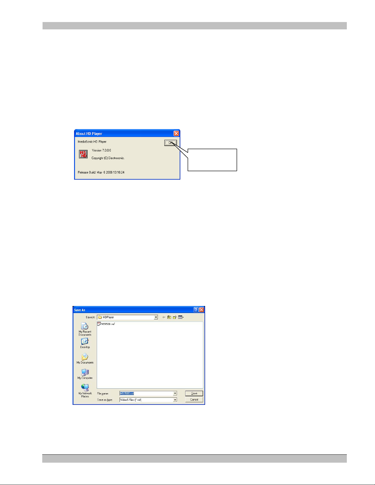
MS9500GL HD FrEND Plus Chapter 3: Player Configuration – HD Application
The Driver Statistics window is used for information only.
The Configurations Menu
Select Configurations/Remote Control Configurations to ope n the Remote Control Wizard.
Note: Refer to ‘Chapter11: Remote Control Configuration for more information.
The Help menu
Select Help/About HD Player to verify the Version of HD Player software on your system.
The About HD Player display:
Click here to
Close
Saving the current configuration
To enable the MS9500GL to “remember” its configuration when the power is turned off and back on,
configuration files are stored on the player hard-disk. These files contain information such as the Playlist (created
by the HD Application), defined remote control methods and startup options.
You may have as many different configuration files as you wish.
These configuration files have the extension. vsf (video player file) files.
To save the current configuration
The current configuration can be saved using the Save As command.
1. Click File/Save As on the main menu. The ‘Save As’ window appears:
2. Enter the name of the file you wish to create (make sure it has a .vsf extension)
3. Click the Save button or hit the ‘enter’ key on the keyboard.
Note: When the HD Player starts up it will automatically load the last saved .vsf file.
31 Rev. 1.26
Page 36

MS9500GL HD FrEND Plus Chapter 3: Player Configuration – HD Application
Once a file has been given a name using the “Save As” command, the “Save” command can be used to speed up
the operation. Save will replace the named file without prompting for a new name.
To save a configuration file:
Click File/Save on the main menu or press Ctrl-S on the keyboard (if connected).
Loading a configuration file
A different configuration can be loaded into the HD Player using the load command.
To load a configuration file:
Click File/Open from the main menu or press Ctrl-O on the keyboard (if connected).
32 Rev. 1.26
Page 37

MS9500GL HD FrEND Plus Chapter 4: Linear Timecode (LTC)
Chapter 4: Linear Timecode (LTC)
NOTE: This chapter applies to the MS9500GL only - the MS9500 does not accommodate LTC. Timecode
related features will appear ‘grayed-out’ in the HD Player interface.
Large control systems often require a number of different, and usually diverse, pieces of equipment to operate
within strict timing constraints. For example, an exhibit may use a video display with an associated multi-channel
audio playback system. A method is required to ensure that the audio playback matches the video display (“Lip
Sync”).
To solve the synchronization problem use a Timecode signal. Timecode, as the name suggests, is a stream of
coded time stamps encapsulated in an audio signal. The frequency of these time stamps is designed to match video
rates for the various video standards in use around the world. There are three common standards in use today.
SMPTE - The SMPTE standard is used in the USA and matches the video rate of 29.97 frames per second.
EBU – This standard matches the PAL specification in use in the United Kingdom, i.e. 25 frames per second.
FILM – This standard matches the 24 frames per second used in the motion picture industry.
A typical timecode based system will incorporate a device that generates the timecode for the system, referred to
as the master timecode. This signal is distributed to each timecode aware device in the system. These are often
referred to as slaves. A slave will usually have the ability to generate its’ output based on the timecode it receives.
For example a lighting system could be programmed to generate a lighting scene or effect when a certain timecode
is received.
The MS9500GL player can operate either as a slave or as a master. This allows for maximum flexibility when
integrating the player in a system. It is even possible for some clips to operate in the master mode while others
operate in the slave mode.
Note: Drop Frame timecode is not supported.
SYNCHRONIZED MULTI-PLAYER OPERATION
SYSTEM COMPONENTS:
The following equipment is required for a minimal synchronized system:
• Two MS9500GL Players.
• Timecode cable.
• Composite black and burst video sync generator. *
• Genlock cables.
• Show control computer (running ESCAN or other control software).
• LAN (TCP/IP) or RS232 remote control cabling.
The two MS9500GL Players are designated as Master and Slave, for the remainder of this description.
Note * - A composite video source. e.g. pattern generator may be used if necessary.
The master HD Player generates a triggering timecode signal for the slave and potentially other components in the
system. Time code signal is fed from its output on the master to the input on the slave unit.
33 Rev. 1.26
Page 38

MS9500GL HD FrEND Plus Chapter 4: Linear Timecode (LTC)
The Genlock signal is fed to both the master and slave from the external Composite black and burst video sync
generator. See chapter 5 for further details.
Note that timecode and genlock can also be provided by external show control equipment. In this case the master
player becomes a slave to the show control equipment.
Ensure that the remote control communication method for the system is correctly connected and functioning.
Synchronized playback using show control
This section explains the commands used to control a synchronized multi-player system. The messages sent to
each player are the same, whether RS232 or TCP/IP is used for the physical connection.
Please refer to chapter 12 of this manual for full details about the command structure and more information about
configuring the HD Players.
Command Descriptions
Playrange <Channel> <start chapter> < end chapter>
Sets the start and end chapters for a Playlist on the specified channel. This command will also pre-load the start
chapter in preparation for a play command.
The Playrange command requires an amount of time to complete (up to 6 seconds depending on the file format
and bit rate), because of some initialization that must occur when a new file is selected. If the HD Player is used in
a simple application where a single file is repeatedly played (in a theater for example) it is more efficient to use
the “loop” command (see Loopon below).
When the Playrange command is complete the HD Player will return the following:
Channel x Cued <cr> <lf> (where x is the base channel set in the channel properties).
Fastseek <Channel> <start chapter> < end chapter>
The fastseek command is a possible alternative to playrange, which can be used in some situations where all the
content in the playlist is of the same format (resolution, frame rate, bitrate and with matching PIDs). By assuming
the content format is identical, the HDPlayer software is able to bypass a lot of initialization and checking, thereby
making the cueing process much faster. However, reliable playback becomes critically dependent on accurate
content preparation and encoding and tight control. Specifically, the playrange command must be used the first
time a file is cued and if the player reaches the end of the playlist a new playrange command must be issued
before fastseek becomes active again.
Tcgenerate <Channel> hh:mm:ss:ff
Turns the timecode generator on and sends the timecode hh:mm:ss:ff out as a jam sync.
Tcreceive <Channel>
Sets the player into timecode receive mode.
Tcreceiveloop <Channel>
Sets the player into timecode receive mode, and loop the incoming timecode to the timecode output.
Tcplayat <Channel> hh:mm:ss:ff
Sets the timecode playat time
34 Rev. 1.26
Page 39

MS9500GL HD FrEND Plus Chapter 4: Linear Timecode (LTC)
Tcstopat <Channel> hh:mm:ss:ff
Sets the timecode stopat time
Tcstart <Channel>
Starts the timecode running (assumes the player is in Generate mode).
CONTROL EXAMPLE
This example is the simplest type of synchronized show. Two players, each load a single clip and play it through
to the end. This technique might be used in a 3D theater for example.
The required sequence of events, triggered by show-control is:
• Cue the players (Playrange command). This command readies the file on each player for playback.
• Program the Master timecode generator (Tcgenerate)
• Program the “Slave” as a timecode receiver (Tcreceive)
• Tell both devices to begin playing at a specific timecode (Tcplayat)
• Tell the master to begin timecode generation (Tcstart)
The HD Players will begin video playback when the timecode specified in the tcplayat command is reached.
Command sequence to play file 0 on both players at 01:00:00:00, with a 5 second timecode lead in.
NOTE: This example assumes both MS9500GL players are using the same base channel (1 in this case).
The player responds to the Playrange when the file loading process is completed. If the show control system is
not using these responses to control the timing of messages to the MS9500GL, a delay will be required between
the fastseek and tcgenerate commands. The actual delay required is dependent on the file and will need to be
determined empirically.
Device 1 "Master" Device 2 "Slave"
Playrange 1 0 0 <cr> Playrange 1 0 0 <cr>
Tcgenerate 1 00:59:55:00 Tcreceiveloop 1 <cr>
Tcplayat 1 01:00:00:00 <cr> Tcplayat 1 01:00:00:00 <cr>
Tcstart 1 <cr>
NOTE: Adjustments to the slave Tcplayat timecode may be necessary to correct for encoding errors.
In the example above the <cr> symbol represents an ASCII carriage return, in practice this should be sent as a
byte with the value 0d (hex) or 13 (decimal).
35 Rev. 1.26
Page 40

MS9500GL HD FrEND Plus Chapter 4: Linear Timecode (LTC)
REFERENCE
For more information on files and encoding, refer to the following appendices:
Appendix B: An Introduction to MPEG
Appendix C: Encoding Guidelines
For more information on setting up communications protocols refer to the following chapters:
Chapter 11: Remote Control Configuration,
Chapter 12: Remote Control Protocols,
Appendix A: TCP/IP Communications.
Synchronized playback using manual local control
Timecode Master
In the master mode the MS9500GL is programmed to generate timecode when an MPEG clip begins playing. This
allows any slave devices to be locked to the video output from the Player. Each clip can have its own unique
timecode and has the ability to generate a pre-roll and/or run-on option.
The Timecode configuration dialog
NOTE: Follow the procedure below only when using the GUI application to control the player. Ensure that
the Clip Properties>Timecode is set to ‘Disabled’ when using a remote control system.
To access the timecode configuration dialog:
1. Right click over an entry in the clip list
2. Select “Clip Properties” from the drop down menu.
3. Select the Generate option in the properties to set the parameters (If using system remote control, set
timecode to ‘Disabled’).
Note: A Clip has to be cued using the transport controls or a remote control message for the timecode settings to
be activated.
36 Rev. 1.26
Page 41

MS9500GL HD FrEND Plus Chapter 4: Linear Timecode (LTC)
Click here
Start Time
This is the timecode that will be generated when a play command is received after the clip is cued. If the Play At
(see below) option is not enabled, this will also be the point when video output begins. The Player will output this
timecode, as a “Jam Sync” signal, when a cue command is issued.
Play At
Select the Play At box and enter a time for clip playback to begin. The difference between the ‘Start Time’ and
‘Play At’ time is known as “pre-roll”, i.e. a period where timecode is generated before the video starts. This might
be used for pre show setup before the video begins.
Stop At
Select the Stop At option set a stop point for the timecode. This time can be before or after the end of the video
output. This might be used for controlling “post show” equipment such as fading house lights up. The Stop At
time is independent of the length of the MPEG clip. Stop At can be used to stop the timecode while the clip is still
playing, or extend the timecode after the clip has ended.
The following examples show some typical uses of the timecode generation options:
Generate a timecode starting at 01:00:00:00 when the play command is received.
37 Rev. 1.26
Page 42

MS9500GL HD FrEND Plus Chapter 4: Linear Timecode (LTC)
Generate a timecode starting at 01:00:00:00 when the play command is received, but delay start of the
video playing until 01:00:10:00.
Generate a timecode starting at 01:00:00:00 when the play command is received. Start the video 10
seconds later (10 second delay) and run the timecode on until 01:05:00:00.
38 Rev. 1.26
Page 43

MS9500GL HD FrEND Plus Chapter 4: Linear Timecode (LTC)
Configuring as a Timecode Slave
In the slave mode the MS9500GL can be programmed to start playing when it receives a particular timecode. A
different timecode can be programmed for each clip in the clip list.
To access the timecode configuration right click over an entry in the clip list and select “Clip Properties” from the
drop down menu. Select the Receive option in the properties to set the parameters
Play At
The Play At box is used to set the trigger point at which the cued file will begin playing.
Loop Input to Output
Select this option to pass incoming timecode through to the timecode output. Use this feature to daisy chain a
number of players to the same timecode input.
Note: In the loop through mode the output timecode is electrically regenerated, i.e. there is no perceptible delay in
the timing between the input and output.
The following example shows a typical use of the timecode receive option:
Play the clip when a timecode of 01:00:10:00 is received.
Note: When using Timecode remote control the ‘tcreceive’ command overrides the loop through settings in
the individual clip properties and stops Timecode loop through. Use the ‘tcreceiveloop’ command to enable
(or maintain) Timecode loop through. Refer to the Timecode Commands list in Chapter 12: Remote
Control Protocols.
39 Rev. 1.26
Page 44

MS9500GL HD FrEND Plus Chapter 4: Linear Timecode (LTC)
In this mode a cue command is required for the timecode trigger to be activated.
Configuring as a Timecode Reader
The MS9500GL can also be used as a simple timecode reader if verification of incoming timecode is necessary.
Simply select the Receive mode but do not check the Play At option. In this mode the Timecode window will
show the incoming timecode without a clip being played.
40 Rev. 1.26
Page 45

MS9500GL HD FrEND Plus Chapter 5: Genlock
Chapter 5: Genlock
NOTE: This chapter applies to the MS9500GL only - the MS9500 does not accommodate Genlock. Genlock
related features will appear ‘grayed-out’ in the HD Player interface.
Genlock provides a method for ensuring that multiple MS9500GL players can operate with synchronous timing on
each of their outputs. Also, the playback timing of each of the players in a ‘genlocked’ system will ensure that the
first frame of video is decoded across multiple Players at the same time.
Genlock Mode
The Player can operate in a single genlock mode (composite black burst) chosen from the Genlock Mode drop
down menu in the Channel Properties dialog box. NOTE: The standalone/master and ES-Gen options listed are
not applicable for the MS9500GL, they are provided for compatibility with other models within the Channel
Properties Dialog window click on the arrow button indicated below:
Click here to select
Genlock Mode.
The Genlock Mode menu shown below will appear:
Select ‘Genlock Composite Black Burst’ mode.
Genlock Composite Black Burst
Select this mode to Genlock the MS9500GL to a composite Black and Burst signal.
It is important that the Genlock signal matches the output standard selected. For example, it is not possible for the
MS9500GL to Genlock to a PAL (50Hz) composite signal if the output mode is set for a 60Hz output mode.
Typically all MS9500GL players in the same system will be connected to a central house sync that is generated
from a video DA.
The figure below shows a typical Composite Black/Burst Cabling Configuration.
41 Rev. 1.26
Page 46

MS9500GL HD FrEND Plus Chapter 5: Genlock
42 Rev. 1.26
Page 47

MS9500GL HD FrEND Plus Chapter 5: Genlock
Chapter 6: The Playlist Display
The Playlist
Use the Playlist area of the HD Player GUI to perform video clip management functions:
• Display and select clips which have been previously loaded on the MS9500GL’s disk drive
• Add new clips
• Set up clip sequences to run in a particular order. The order may be changed by simply dragging the clip
to a new position within the sequence
The Playlist also allows access to many of the powerful features and settings of the HD Player, namely:
• The Clip Properties Dialog – This dialog controls Clip specific configurati ons
• The Channel Properties Dialog – This dialog controls system configurations. Refer to Chapter 3: Player
Configuration - HD application
Note: After Editing the Playlist or any of the Dialogs mentioned above, you must save the configuration to ensure
the Playlist is available when the HD Player is next restarted. See the ‘Saving the current configuration’ section
in Chapter 3 for more details.
The following figure defines the data that appears in the Playlist:
Pointer 1
Pointer 2
Chapter
Number
Clip
Name.
• Clip Name
• Chapter Number: Defines the Clip position in the list
• Pointers 1 and 2: Define the start and end clips in a playlist.
Adding a clip to the Playlist
There are three methods that can be used to add clips to the Playlist.
• Double Click a blank entry in the Playlist. This will display the Clip Properties dialog box, from which
an MPG file can be selected. See ‘The Clip Properties Dialog’ section following.
• Right Click an existing entry in the Playlist and click Clip Properties from the list. The Clip Properties
dialog appears. See ‘The Clip Properties Dialog’ section following.
• Drag and Drop: Open an explorer window, select one or more files and drag them onto the Playlist. As
the mouse is moved over the Playlist area, a highlight bar will appear indicating where the files will be
placed. See ‘The Clip Properties Dialog’ section following.
43 Rev. 1.26
Page 48

MS9500GL HD FrEND Plus Chapter 5: Genlock
You may re-order clips in the Playlist at any time; simply drag files to different positions within the Playlist as
necessary.
The Clip Properties Dialog
The Clip Properties dialog box is used to set various parameters relating to the clips in the HD Player Playlist.
Open this dialog window by right clicking over a clip in the Playlist, and selecting the “Clip Properties” menu
item.
The Clip Properties dialog appears, as shown below:
Clip (name)
The clip name specifies the location and name of the MPEG transport file.
• Click the Browse button to display a standard file selection window that can be used to locate the required
file.
44 Rev. 1.26
Page 49

MS9500GL HD FrEND Plus Chapter 5: Genlock
Selecting and Playing a Clip
Use the GUI to manually choose and play a clip.
To Play a Clip
1. Double click any clip in the Playlist, this will Cue the start of the clip
2. Click (Play) button on the Transport to begin playing the clip. A video image will appear on the
display connected to the MS9500GL.
3. Click (Pause/Stop) button to quit and click again to play from the pause point or, click the
button and the MS9500GL will re-cue the clip (this may take a few seconds); next, click to
play the clip from the beginning.
Alternatively you may:
1. Drag both arrows at the left of the Playlist up or down to the clip you wish to play
2. Click the (Cue) button on the Transport
3. Click the
(Play) button on the Transport to begin
IR Remote (Hand-Held)
Use the Hand-Held IR Remote to play a clip:
• PLAY - Cues and Plays the FIRST clip in the HD Player Application Playlist
• STOP – Stops the clip and displays a blank screen.
NOTE: The IR remote will not function if no clips are present in the HD Player playlist.
Selecting and Playing a List (Sequence)
1. Drag the top pointer at the left of the Playlist to the beginning clip of the sequence
2. Drag the remaining pointer at the left of the Playlist to the end clip of the sequence
3. Place intermediate clips in any order you wish by dragging to their required position in the order. If only
two files make up the Playlist, the first file to be played will be the first file listed.
4. Click the Cue button on the Transport Control
5. Click the Play button in the Transport Control
NOTE: To ensure quality playback, all Video files within a Playlist must use the same resolution, frame rate, and
PID numbers.
45 Rev. 1.26
Page 50

MS9500GL HD FrEND Plus Chapter 7: Scenes
Chapter 7: Scenes
Scenes are user-defined (preset) screen layouts output by the MS9500GL to the display device.
Scenes are created on a ‘local’ computer running the On Screen Display Designer (OSD Designer) software
available free with the MS9500GL.
The OSD software Interface:
A Scene is produced by the integration of video (MPG), still images (BMP), HTML (Web) pages scrolling
‘Tickers’ (RSS or Text) and other elements. They are defined within .scn files that consist of ‘Regions’ which
contain definitions unique to each type of medium.
A Region is defined by certain parameters which the user can alter to vary the location, appearance and content of
the region. Up to six user-definable Regions are available for incorporating into any Scene.
NOTE: All but the Video ‘Region’ may be defined in multiple instances on the display.
The user may wish to use an existing Scene as a template for a new scene (by copying the scene from the
MS9500GL and editing it on the local computer) or, generating a new scene. The Scene is then transferred to the
MS9500GL.
Refer to the accompanying document ‘On Screen Display Designer (OSD Designer)’ that was provided as
part of the MS9500GL package. The document explains the Installation and use of the OSD Designer interface
to generate Scenes for loading on the MS9500GL. The OSD application also offers methods for creating Playlists
and Schedules (for content management).
The OSD Designer application is provided on a CD with the MS9500GL for installation on any ‘local’ Windows
based computer
46 Rev. 1.26
Page 51
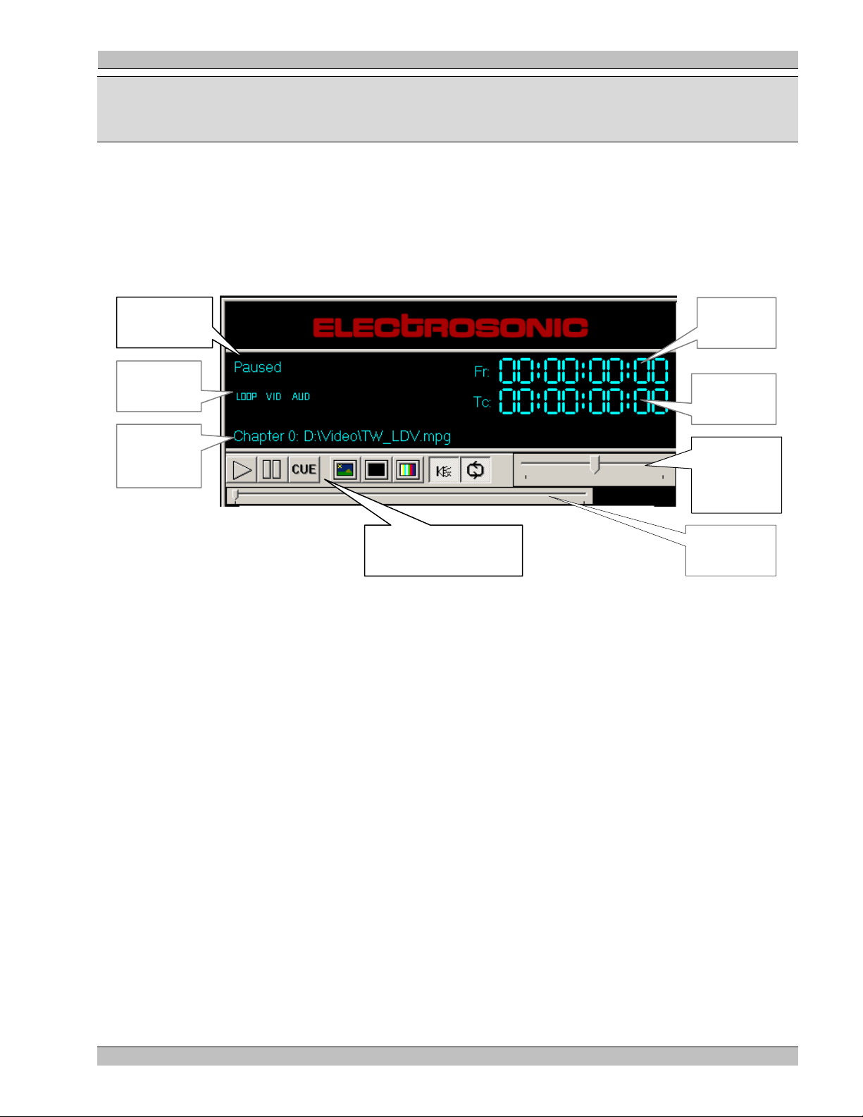
MS9500GL HD FrEND Plus Chapter 8: Transport & Status Display
Chapter 8: Transport Status Display
The HD Player interface is similar to that of a simple tape player: The tape is played until it reaches the end, when
a rewind is required to play again. In the case of the MS9500GL this rewind (Cue) is near instant, but the
metaphor provides a useful description.
The Status display is linked to the Transport Controls and shows various pieces of useful information about the
current state of the MS9500GL:
Transport
Status
Mode
Indicators
Current
Chapter
and File
Transport + Output
Mode Buttons
Cue To
Slider
Frame
Counter
Current
Timecode
Analog
Audio
Volume
Transport status
The transport status shows the current operating state of the MS9500GL. The display will show one of the
following messages.
Stopped
The Stopped indicator appears at Start-up of the HD Player software, only. The status will change when the first
file is cued.
Paused
The Paused indicator is displayed under the following circumstances.
• Paused will be shown after a file has been cued.
• Paused will be displayed if a file has been played and then stopped using either the transport controls or a
remote control message.
Cueing
The Cueing indicator will be shown when
• The cue button has been selected from the transport controls
• The user double-clicks a clip in the Playlist – selecting the Play button will run the cued clip
47 Rev. 1.26
Page 52

MS9500GL HD FrEND Plus Chapter 8: Transport & Status Display
• A play range command has been received through a remote control interface.
During the cueing process, the MS9500GL searches the MPEG clip for the first displayable picture and initializes
the video output to the requested resolution. The Cue process ensures that when a play command is received the
MPEG decoder is primed and ready to play. This is essential in multi-channel systems where a predictable startup
is a requirement.
Playing
The playing indicator will be displayed while the MS9500GL is decoding the MPEG stream.
Frame Counter
The frame counter shows the current clip position in hours, minutes, seconds and frames.
Note: This number is relative to a start frame of 0, i.e. the first frame decoded in the MPEG stream will be shown
as 00:00:00:01
Current Timecode
The timecode counter shows the current timecode output when operating as a generator or external input when set
to receive. Shows hours, minutes, seconds and frames.
Mode Indicators
The Mode indicators are used to illustrate various on/off style settings on the HD Player. These modes are:
Loop
This indicator will be on when the Auto-repeat mode is selected. The auto-repeat mode can be selected from the
transport controls. When this option is set and the decoder reaches the end of an MPEG clip, playback will
continue from the first frame of the MPEG clip. This ensures continuous playback.
Note: The visual quality of the loop is dependent on how the MPEG stream ends. For full details of how to ensure
clean looping, please refer to the encoding considerations later in this manual.
Vid
This indicator will be on if the video output is active. It will be off when the video outputs are muted (black).
Video syncs are maintained while in muted mode.
Aud
This indicator will be on if the audio output is active. It will be off when the audio is muted. Audio mute will mute
both the SPDIF and Stereo Analogue audio.
48 Rev. 1.26
Page 53

MS9500GL HD FrEND Plus Chapter 8: Transport & Status Display
Current Chapter and Clip Name
The Current Chapter field indicates the name of the file that is currently in playback or cued for playback. This
entry will change as a result of the cue command.
Note: The term Chapter refers to a file in the Playlist. The meaning is analogous to the term used in reference to
DVDs. Here chapter refers to a section of the disc.
Transport/Output Controls
Play
Click this button to start the Clip or Playlist playing.
Cue
Click this button to load a clip from the Playlist (“rewind” a clip to the beginning) prior to
a restart.
Note: If the clip is the first file in a Playlist then a play command will cause the entire
playlist to run.
Pause
Click this button to pause the Clip playing.
Auto-repeat (Loop)
Click this button to toggle the auto-repeat mode on or off. When this option is selected, a
playing file or Playlist will restart from the beginning when it reaches the end.
Audio Output
Click this button to toggle the audio output on or off.
Video Output: Black
Click this button to mute (set to black) the video output.
Video Output
Click this button to activate the Video output, following either a video mute, or color bars
command.
Color Bars
Click this button to display color bars on the video outputs.
Fast Forward/Loop Slider
• Drag this Slider to Cue to any position in a clip. Click the Play button to play from the new position.
49 Rev. 1.26
Page 54

MS9500GL HD FrEND Plus Chapter 8: Transport & Status Display
Analog Audio Volume Slider
• Drag this ‘Slider’ to adjust analog audio output +30dB/-97dB.
50 Rev. 1.26
Page 55
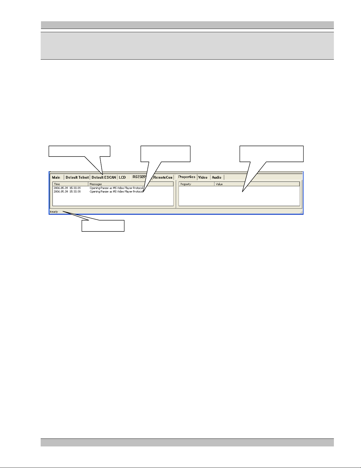
MS9500GL HD FrEND Plus Chapter 9: The Log/ File Information Windows
Chapter 9: The Log / File Information Windows
The Information display at the bottom of the GUI is divided into two (left and right) main segments:
• The Log Window on the left, and
• The File Information Window on the right
• Additionally, the Status Bar is located at the very bottom left of the display
These windows display various pieces of useful information about the HD Player while it is running. The
information shown can be used to “debug” show control programming problems, check communications protocols
and generally monitor the condition of the HD Player.
Click tab as required
Log Window File Info. Window
The Log display is arranged as a set of “pages” each listing related information. The active tab, i.e. the one whose
entries are being displayed, can be selected by clicking over it’s name, as illustrated in the following diagram.
The Log Window
The Log Window displays various Log Tabs:
• Main - Shows details about the unit’s status, such as when files are cued and played, when the audio or
video is muted etc.
• Default Telnet – Shows details on the default Telnet Remote Control ‘Method’. Refer to Chapter 11.
• Default ESCAN – Shows details on the default ESCAN Remote Control ‘Method’. Refer to Chapter 11. .
• LCD – Shows details on the LCD interface.
• RS232Port – Shows details on RS232 Remote control ‘Method’. Refer to Chapter 11. .
• User Defined (not a default) – This is a remote control connection through server Port 23. A log tab
“RemoteCon” for example is created for each remote control method defined by the user. These tabs
display any commands received by that method and will also show any protocol errors encountered. (See
Chapter 11: Remote Control Configurations, also, Chapter 12: Remote Control Protocols)
51 Rev. 1.26
Page 56

MS9500GL HD FrEND Plus Chapter 9: The Log/ File Information Windows
User Defined Tab
The File Information Window
The File Information Window displays various properties unique to the current clip:
• Properties – Data Rate of the clip
• Video – Horizontal and Vertical Resolution, Frame Rate and PID
• Audio – Sample Rate, Channels, Format, Bit Rate and Frame Time
Click the appropriate tab to view the page contents.
Status Bar
Refer to the section ‘The View Menu’ in Chapter 3.
52 Rev. 1.26
Page 57

MS9500GL HD FrEND Plus User Guide Chapter 10: Data Transfer
Chapter 10: Data Transfer
Loading MPEG (.mpg) data files:
MPEG encoded HD or SD video clips (MPEG transport streams) must be loaded on to the MS9500GL’s hard disk
in order to be played (sent to a display device).
Transfer all video files to the default folder in the MS9500GL (a default test MPEG file is included with the
MS9500GL); this is the D:\Video folder.
The user has two methods available for loading MPEG data into the MS9500GL:
• ETHERNET port on the back panel – Connect the MS9500GL to your LAN and transfer MPEG data
from your file storage system (or another computer) with any FTP application.
• USB interface on the back panel – Connect the MS9500GL to another computer or to a portable drive
and transfer files to the MS9500GL
Use the FTP application of your choice to up-load MPEG (.mpg) files stored on a “local compu ter” to the
MS9500GL. Follow the directions given with the specific application for transferring data between computers.
For the purpose of example we will describe two methods for file transfer:
1. The DOS command window
2. Internet Explorer
Perform these procedures with any Windows based PC.
The MS9500GL “remote computer” and the computer containing video files for transfer (“local computer”) must
be connected to a network.
NOTE: Do not change the password to the hdclipftp user.
Loading Scene (.scn) data files:
Scene (.scn) data must be loaded on to the MS9500GL’s hard disk in order to implement a user defined display
device layout (scene).
Transfer all Scene files to the D:\Scenes folder in the MS9500GL (a number of default Scene files are included
with the MS9500GL).
The user has two methods available for loading .scn data into the MS9500GL:
• ETHERNET port on the back panel – Connect the MS9500GL to your LAN and transfer the .scn data
from your file storage system (or another computer) with any FTP application.
• USB interface on the back panel – Connect the MS9500GL to another computer or to a portable drive
and transfer .scn files to the MS9500GL
Use the free Electrosonic OSD Designer software or a FTP application of your choice to up-load Scene (.scn) files
stored on a “local computer” to the MS9500GL. Follow the directions given with the specific application for
transferring data between computers.
For the purpose of example we will describe two methods for file transfer:
1. The DOS command window
2. Internet Explorer
53 Rev. 1.26
Page 58

MS9500GL HD FrEND Plus User Guide Chapter 10: Data Transfer
Perform these procedures with any Windows based PC.
The MS9500GL “remote computer” and the computer containing .scn files for transfer (“local computer”) must be
connected to a network.
NOTE: Do not change the password to the hdclipftp user.
To Up-Load data with the DOS window:
1. Select Start/Run/ and type: cmd as shown; click OK
A window similar to the following should appear:
2. At the command prompt enter: f t p XXX.XXX.XXX.XXX (where X…X is the IP address of the
MS9500GL from the Chapter 2: Player Configuration – LCD, Communications, Set IP Address). Press
Enter/Return.
3. Enter the User Name: ftpuser (case sensitive), press Enter/Return when prompted.
4. Enter your password: electrosonic (case sensitive), press Enter/Return when prompted.
5. IMPORTANT! Type binary in the command line and press Enter/Return. This ensures that data is
transferred to the MS9500GL correctly.
6. Type: dir in the command line, press Enter/Return. The application will display the contents (directory
structure) of the MS9500GL (D:\).
7. Type: CD Video or CD Scenes. The application will display the contents of the \Video folder or \Scenes
folder.
8. Type: put <path>\<filename> and press Enter/Return to send a file from the local computer to the
current folder on the MS9500GL.
NOTE: MPEG video file sizes may be very large. The time taken to up-load will be dependent on the file
size as well as the bandwidth of your network connection. Check for the ‘Transfer Complete’ message as
shown above to ensure that your files have completely transferred to the MS9500GL before trying to play
them. XML files are relatively small and their transfer should happen almost instantaneously.
54 Rev. 1.26
Page 59

MS9500GL HD FrEND Plus User Guide Chapter 10: Data Transfer
9. Type: quit or bye to exit.
10. Close the DOS window.
Having transferred your data to the MS9500GL you can now play your video files or run Scenes.
To Delete a file from the MS9500GL using DOS
If necessary you may remove files from the MS9500GL:
1. Open a DOS window and log on to the MS9500GL as shown above.
2. Open the \Video or the \Scenes (Step 7 in preceding sequence).
3. Type: del filename enter/return in the command line. The file will be removed from the appropriate
folder on the MS9500GL.
To Up-Load data with Internet Explorer
1. Open Internet Explorer on the local computer.
In the Address line, as shown above, type the IP address for your MS9500GL (from Chapter 2,
Communications, Set IP Address), press Enter/Return.
Press Enter/Return; the following Login dialog box will be displayed:
2.
Enter the User Name: ftpuser (case sensitive)
Enter the Password: ftpuser (case sensitive).
Click Login. The MS9500GL file D:\ folder is displayed.
3. Browse to the D:\Video folder or the D:\Scenes folder.
55 Rev. 1.26
Page 60

MS9500GL HD FrEND Plus User Guide Chapter 10: Data Transfer
4. Open a file manager window by clicking My Computer on the desktop of the ‘local’ computer.
5. Select the file(s) you wish to transfer (Video or Scene) and drag/drop from the My Computer window
(local computer) to the Internet Explorer window (MS9500GL).
NOTE: MPEG video file sizes may be very large. The time taken to up-load will be dependent on the file size as
well as the bandwidth of the network connection. Ensure that the files have completely transferred to the
MS9500GL before trying to play them. Scene files are relatively small and their transfer should happen almost
instantaneously.
Having transferred the program material to the MS9500GL you are now ready to play the files.
To Delete a file from the MS9500GL using Internet Explorer
If necessary you may remove files from the MS9500GL:
1. Open Internet Explorer and log on to the MS9500GL as shown above
2. Open either the D:\Video or the D:\Scenes folder
3. Select the file you wish to remove from the list in the window
4. Right click the file and select Delete from the menu. The file will be removed from the appropriate
folder on the MS9500GL.
56 Rev. 1.26
Page 61

MS9500GL HD FrEND Plus Chapter 11: Remote Control Configuration
Chapter 11: Remote Control Configuration
Two specific components are required for the remote control of the HD Player: a physical link and a protocol.
The MS9500GL uses two types of physical links, RS232 serial, or Ethernet using TCP/IP.
A number of different protocols are available for interface with standard control systems.
In order to use the Player for remote control a ‘Method’ must be created. This provides the link between physical
medium, protocol, and video channels. Methods are created using the ‘Remote Control Methods wizard’. This can
be reached from the configuration menu.
Click on Configurations/Remote Control Configurations in the main menu to display the Remote Control
Methods wizard described in the following section.
The Remote Control Methods dialog
The initial Remote Control Methods display shows a list of methods that have been defined so far. The
number of methods allowed is unlimited and can use any combination of RS232 and TCP/IP.
NOTE: The default serial control settings for the MS9500 are Control, 38400, N, 1.
To create a new Method
Click the New button located to the right of the dialog. This will invoke the Method Type page of the Remote
Control Wizard. The wizard follows the format commonly found in Windows based software, where a series of
screens appear requiring information to be entered. When you have entered the details required in a screen, use the
“Next” button to move on to the next page. The Back button can be used at any time to step to the previous page.
To Edit Method settings
Click the Method name and then click the now active Edit button. This will produce the remote method wizard,
from where the required settings can be changed.
To Delete a Method
Click the Method name then click the now active Delete button. A confirmation prompt will appear, to prevent
accidental deletion.
Click the Delete All button to remove all methods from the table. Care should be taken using this option, since it
cannot be undone.
The following sections describe each page of the wizard.
57 Rev. 1.26
Page 62

MS9500GL HD FrEND Plus Chapter 11: Remote Control Configuration
The Remote Control Wizard - Method Type dialog
The first screen in the wizard requires two pieces of information, the method name and the physical connection
type. Every method must have a unique name, which is used to identify the method in the Log window. There are
currently two physical connection types, Serial (RS232) and TCP/IP.
Click here to choose a type
Click on the list to select either Serial or TCP/IP
Click Next to advance to either the Serial Control Parameters page or the TCP/IP Configuration page.
Information for the Serial Control Parameters is given next, followed by information for TCP/IP Configuration.
The Remote Control Wizard - Serial Control Parameters (RS232) page
This page of the wizard will appear if Serial (RS232) was selected from the “Method Type” page described above.
The page is used to select the parameters for the serial port, from the following allowable settings.
Serial port: Choose from the COMs available
BaudRate: 1200, 2400, 4800, 9600, 19200, 57600, 115200.
Parity: Odd, Even or None.
Stop Bits: 1 or 2 stop bits.
58 Rev. 1.26
Page 63

MS9500GL HD FrEND Plus Chapter 11: Remote Control Configuration
To modify the Serial Control Parameters: Click the arrow buttons adjacent to the appropriate boxes and select the
necessary settings from the options listed then, Click the Next button to accept the settings and advance to the
Choose Protocol page.
Remote Control Wizard Protocol page
Use this page to select the protocol necessary for a specific Remote control Method. A detailed description of the
available protocols is provided in the “Protocol Reference” section later in this manual.
1. Click on the list to select a Protocol
2. Click Next to advance
3. Click Finish to end. This will return you to the Remote Control Methods. A new method will be
displayed in the list:
The Remote Control Methods wizard TCP/IP page
The following window results after selecting the TCP/IP option and clicking Next on the “Method Type” page of
the Remote Control Wizard. There is only one parameter required, the TCP/IP port to use for the connection. It is
usually safe to select ports above the value 2000, although any number can be used in a closed installation.
59 Rev. 1.26
Page 64

MS9500GL HD FrEND Plus Chapter 11: Remote Control Configuration
Enter Port
Number 4000
1. Enter the port number in the window.
2. Click Next to advance to the Protocol page.
3. Choose a protocol for this channel from the drop-down list:
MS Video Player Protocol
ES4000 H-Type Parser v1.02
Text Command Protocol v1.07
LCD
4. Click on the list to select a Protocol.
5. Click Next to advance
6. Click Finish to end.
A new tab will appear in the Information Window for each method created:
New Remote
Control method
Tab
60 Rev. 1.26
Page 65

MS9500GL HD FrEND Plus Chapter 12: Remote Control Protocols
)
Chapter 12: Remote Control Protocols
The HD Player facilitates remote control with Serial and LAN connectors located at the rear. We recommend that
you use commercially manufactured connecting cables. Should you wish to make your own cables, the HD
Player’s control pinouts are given below.
Serial Port Pinout
9 WAY D TYPE PLUG
(FRONT VIEW)
15
69
PIN1 Data carrier detect
PIN2 Receive data
PIN3 Transmit data
PIN4 Data Terminal ready
PIN5 Ground
PIN6 Data set ready
PIN7 Request to send
PIN8 Clear to send
PIN9 Ring Indicator
Figure 6. Serial Port Pin Functions
RJ45 Ethernet
This is a 100 Base T connection that supports the TCP/IP protocol.
RJ45 Pinout
(DCD
(RXD)
(TXD)
(DTR)
(SG)
(DSR)
(RTS)
(CTS)
(RI)
Pin No Signal Pin No Signal
1 Tx+ 5 No connect
2 Tx- 6 Rx3 Rx+ 7 No connect
4 No connect 8 No connect
Text Command Protocol (Telnet Protocol)
The Text Command Protocol is a simple ASCII text based control method primarily designed for easy control
through a TCP/IP connection or a serial port.
61 Rev. 1.26
Page 66

MS9500GL HD FrEND Plus Chapter 12: Remote Control Protocols
The simplest way to test and experiment with the protocol is to connect the Electrosonic HD Player to a remote
computer running the Telnet program (supplied with all Windows™ operating systems), and to enter commands
using the remote computer’s keyboard.
To Run Telnet
1. Click the Windows Start icon on your desktop
2. Select Run. The window below opens:
3. Enter “Telnet” in the text box and click the OK button
The Telnet window appears:
Enter your commands using the Command Structure shown in the following section.
NOTE: The MS9500GL currently supports a single HD output. To allow for future expansion and to provide
compatibility across all Electrosonic Player products, the Telnet protocol requires a channel number. This
parameter should be set to 1 in the single channel version unless it has been changed using the Base Channel
Number setting in the Channel Properties window (Refer to Chapter 3, Channel properties, Base Channel
Number).
Command Structure
The basic structure for a telnet command is as follows:
KeyWord <channel no> <parameter> <terminator>
The channel no (channel number) is mandatory. For the HD Player use 1 unless you have changed the Base
Channel Number setting in the Channel Properties window (Refer to Chapter 5: HD Player Configuration).
The parameter is only used on some commands. For instance, it could be a chapter number.
The terminator can be either, a Carriage Return, a Carriage Return & Line Feed, or a NULL (0x00).
Commands are
NOTE: In the following Command Reference Chapter = MPEG File
not case sensitive.
62 Rev. 1.26
Page 67

MS9500GL HD FrEND Plus Chapter 12: Remote Control Protocols
Command Reference
NOTE: With asynchronous commands such as ‘loadplaylist’, ‘play’, ‘stop’, etc. the 9500 sends an "OK" message
to acknowledge only that the command was received by the player. However, this message does
player has begun to process the command.
Each section below describes related commands:
In every case, the command to the player must be terminated with an ASCII carriage return character 0d(hex) or
13(decimal).
Configuration Commands
GetPlayerType
This command requests the type of player. The player will respond with:
PlayerType <string1> <number>
Where: String1 = Player type from the player type list below.
Number = software version.
not mean that the
The software version will be a numerically increasing version number
Player Type Description
MS9100HD 9100 series based HD players
MS9200HD 9200 series based HD players.
MS9300SD 9300 series based SD players
MS9400HD 9400 series based HD players
MS9500HD 9500 series based HD players
GetChannelCount
This command requests the number of channels present on the player. The player will respond with:
ChannelCount <number>
SetOutputMode <channel> <string>
This command is used to set the output mode for the player.
<String> is taken from the output mode table.
Mode Description
RGBHV RGBHV Component video output
YprPb YPrPb component video output
RGBs RGB with separate composite syncs (not sync on green)
63 Rev. 1.26
Page 68

MS9500GL HD FrEND Plus Chapter 12: Remote Control Protocols
The Player will respond with:
OK or ERROR
GetOutputMode <channel>
This command is used to get the current output mode for the player. The Player will respond with:
OutputMode <string>
String is taken from the Output mode table.
GetOutputResolution <channel>
This command is used to retrieve the current output resolution and frequency for the player.
The Player will respond with:
OutputResolution <channel> <string> <number>
Where string contains an entry from the Output resolution table and number contains an entry from the
frequency table (below). Example: outputresolution 1 1920 1080 “i” 59
SetOutputResolution <channel> <string> <number>
This command is used to set the output resolution and frequency for the player.
<String> is taken from the resolution table and must be a valid return option from the GetOutputResolution
command.
<Number> is taken from the frequency table and must be a valid frequency for the output resolution.
The resolutions (except video) must have either an I or P appended to the name to indicate Interlace or
Progressive.
Example: setoutputresolution 1 1920 1080 i 59 (string = resolution; from the table) (number = frequency; from
the table)
Resolution Description Freq.
50
720x480
720x576
1024x768
1280x720
1920x1080
X X
X
X
X X X
X X X
Freq.
59.94
Freq.
60
The Player will respond with:
OK or ERROR
64 Rev. 1.26
Page 69

MS9500GL HD FrEND Plus Chapter 12: Remote Control Protocols
Media Management Commands
GetMediaTree
This command is used to retrieve the media storage tree from the player.
NOTE: This command does not return a file listing, only the MS9500GL tree structure.
The player responds with a series of path commands with the following structure; the tree is terminated with an
empty MediaBranch command:
MediaBranch <channel list> <mediapath>
The <channel list> specifies the channels that can use the media (This will be ‘1’ in the MS9500GL).
<mediapath> specifies the name of the branch in a tree format using a UNIX style format. The control
system will not interpret the string but will pass it back to the player when creating playlists.
The GetMediaTree command essentially performs a left hand depth first traverse of the media tree.
The following exchange shows an example response from the player.
MediaBranch 1 “/D:/Video/subfolder1”
MediaBranch 1 “/D:/Video/subfolder2/old video”
MediaBranch
In this example the player wraps two hard drives (e and f) into a UNIX style tree by simply using the letter as the
root of the tree.
GetClips <mediapath>
This command lists the clips available in a MediaBranch passed in the <string> parameter.
The player responds with a series of clip commands with the following structure. The clip list is terminated with
an empty Clip command.
Clip <mediapath> <clip>
Where <string1> contains a branch returned by GetMediaTree, and <string2> is the name of a clip.
The following exchange shows an example response from the player.
Control: GetClips /D:/Video
Player: Clip /D:/Video “clipname1.mpg”
Player: Clip /D:/Video “clipname2.mpg”
Player: Clip /D:/Video “clipname…N.mpg”
Player: Clip
65 Rev. 1.26
Page 70

MS9500GL HD FrEND Plus Chapter 12: Remote Control Protocols
Playlist Commands
ClearPlaylist <string>
This command clears all the entries from the playlist identified by <string>.
The Player will respond with:
OK or ERROR
ListAllPlaylists
Returns a list of all the playlists stored in the server.
The player responds with a list of Playlist commands as follows:
playlist <string1>
Where <string1> identifies a playlist. The list is terminated with an em pty Playlist message.
Example:
Playlist “Left Screen”
Playlist “Right Screen”
Playlist
AddPlaylist <listname> <medianame> <0> <0>
Adds a clip identified by <medianame> to the playlist identified by <listname>.
Note: The <0><0> values are reserved for future development and must be entered with each command line.
The Player will respond with:
OK or ERROR
Example:
AddPlaylist “Left Screen” “Main screen intro.mpg” “0” “0”
AddPlaylist “Left Screen” “Main screen L.mpg” “0” “0”
The control system doesn’t need to terminate the playlist creation commands since the functionality is implied in
the command.
LoadPlaylist <Channel list> <string1>
Loads the playlist identified by <string1> onto the channels specified in <Channel list>. The clips specified in the
playlist must be available to all channels identified in <Channel list>.
The Player will respond with:
OK or ERROR
66 Rev. 1.26
Page 71

MS9500GL HD FrEND Plus Chapter 12: Remote Control Protocols
ListPlaylist <string1>
Returns a list of the clips contained in the playlist identified by <string 1>.
The player responds with a list of PlaylistEntry commands as follow:
PlaylistEntry <string1> <mediapath> <clip>
Where <string1> identifies a playlist, <string3> identifies a media clip located in the media path
identified by <string2>.
The list is terminated with an empty PlaylistEntry message.
Example:
PlaylistEntry “Left Screen” “/D:/Playlists” “Main screen intro.mpg”
PlaylistEntry “Left Screen” “/D:/Playlists” “Main screen L.mpg”
PlaylistEntry
Switchplaylist <Channel list> <string>
The player will perform a seamless switch to another playlist at the end of the currently playing clip.
The Player will respond with
OK or ERROR
Example:
Switchplaylist 1 “Playlistname”
Playrange <Channel list> <start chapter> < end chapter>
Sets the start and end chapters for a Playlist on the specified channel. This command will also pre-load the start
chapter in preparation for the Playlist command.
The Playrange command requires an amount of time to complete, because of some initialization that must occur
when a new file is selected. The status commands can be used to po ll the pl ay er to find out when the playrange
command completes. If the HD Player is required to simply repeat-play the file (in a theater for example) it is
more efficient to use the “loop” command (see Loopon below).
The Player will respond with:
OK or ERROR
Fastseek <Channel list> <start chapter> <end chapter>
Seek to a new file in the playlist as quick as possible. This command should only be used if all files in the playlist
are the same format (resolution, frame rate, bit rate and PID’s):
OK “channel ‘X’ cued” or ERROR
67 Rev. 1.26
Page 72

MS9500GL HD FrEND Plus Chapter 12: Remote Control Protocols
Startscheduler <1>
This command is used to begin a preset schedule on the player.
The ‘1” refers to Channel number and is optional.
Player will respond with:
OK “channel ‘X’ cued” or ERROR
Stopscheduler <1>
This command is used to end the currently running schedule.
The ‘1” refers to Channel number and is optional.
Player will respond with:
OK “channel ‘X’ cued” or ERROR
Scene Commands
LoadScene <Channel list> <scene name>
Loads a (pre-defined) XML ‘Scene’.
The Player will respond with:
OK or ERROR
Playback Commands
Play <Channel list>
Play the currently loaded playlist
The Player will respond with:
OK “channel ‘X’ playing” or ERROR
Stop <Channel list>
Stops the currently playing file and turn video off.
The Player will respond with:
OK “channel ‘X’ paused” or ERROR
Pause <Channel list>
Pauses the currently playing file.
The Player will respond with:
OK “channel ‘X’ paused” or ERROR
68 Rev. 1.26
Page 73

MS9500GL HD FrEND Plus Chapter 12: Remote Control Protocols
Seek <Channel list> <frameno>
Seek to a position in the file. The position is specified as a frameno.
The Player will respond with:
OK “channel ‘X’ cued”/”channel ‘’ playing” or ERROR
Note: This will seek to the next closest index point (i.e. I frame) to the frameno
Audioon <Channel list>
Turn audio on for the requested channel.
The Player will respond with:
OK or ERROR
Audiooff <Channel list>
Mute the audio on the requested channel.
The Player will respond with:
OK or ERROR
Volume <Channel list> <right> <left>
Set the audio output level between 0 and 100 (inclusive; this is a percentage of the maximum output level) for
each side of the stereo audio output.
Example: Volume 1 90 90 = Player 1 outputs 90% of maximum audio. Note: Ensure that values for <right> and
<left> are the same.
The Player will respond with:
OK or ERROR
Videoon <Channel list>
Turn on video for the requested channel.
The Player will respond with:
OK or ERROR
Videooff <Channel list>
Turn off (“Mute”) video on the required channel.
The Player will respond with:
OK or ERROR
69 Rev. 1.26
Page 74

MS9500GL HD FrEND Plus Chapter 12: Remote Control Protocols
Videobars <Channel list>
Turn on video color bar output for the requested channel.
The Player will respond with
OK or ERROR
Loopon <Channel list>
Enable the Auto repeat mode. This will cause the channel to loop (auto-repeat) at the end of the selected files in
the playlist.
The Player will respond with:
OK or ERROR
Loopoff <Channel list>
Turn off the loop flag for the requested channel.
The Player will respond with:
OK or ERROR
Timecode Commands
NOTE: This section applies to the MS9500GL only - the MS9500 does not accommodate Timecode.
Tcgenerate <Channel list> <timecode>
Turns the timecode generator on and sends the timecode hh:mm:ss:ff out as a jam sync.
The Player will respond with:
OK or ERROR
Tcreceive <Channel list>
Sets the player into timecode receive mode.
The Player will respond with:
OK or ERROR
Tcreceiveloop <Channel list>
Sets the player into timecode receive mode and loop the input timecode to the output.
The Player will respond with:
OK or ERROR
Tcplayat <Channel list> <timecode>
Sets the timecode playat time
The Player will respond with:
OK or ERROR
70 Rev. 1.26
Page 75

MS9500GL HD FrEND Plus Chapter 12: Remote Control Protocols
Tcstopat <Channel list> <timecode>
Sets the timecode stopat time
The Player will respond with:
OK or ERROR
Tcstart <Channel list>
Starts the timecode running (assumes the player is in Generate mode – refer to “The Timecode configuration
dialog” section of Chapter 6: Timecode)
The Player will respond with:
OK or ERROR
GPIO COMMANDS:
NOTE: This section applies to the MS9500GL only - the MS9500 does not accommodate GPIO.
When using the MS9500GL GPIO Interface module additional commands are available that enable the
MS9500GL to control or be controlled by an external device.
NOTE: Refer to Chapter 13: Using the GPIO Interface for more information.
Getinput
Verify the state of the four (4) GPIO Inputs.
The Player will respond with
inputstate 1(+ or -) 2(+ or -) 3(+ or -) 4(+ or -) where ‘+’ = ON ‘-‘ = OFF.
Getoutput
Verify the state of the four (4) GPIO Outputs.
The Player will respond with
outputstate 1(+ or -) 2(+ or -) 3(+ or -) 4(+ or -) where ‘+’ = ON ‘-‘ = OFF.
Setoutput
Change the state of the four (4) GPIO Outputs.
The Player will respond with
outputstate 1(+ or -) 2(+ or -) 3(+ or -) 4(+ or -) where ‘+’ = ON ‘-‘ = OFF.
System/Status Commands
Shutdown
Shut the Player system down.
The player doesn’t send a response to this command.
71 Rev. 1.26
Page 76

MS9500GL HD FrEND Plus Chapter 12: Remote Control Protocols
Reboot
Reboot the HD Player.
The player doesn’t send a response to this command.
Getstate <Channel list>
Request the status of certain parameters for a specific player (Channel)
The Player will respond with:
Statetc 1 “00:00:00:00” (“current timecode”)
Statefile 1 “clip” “
(current clip”)
Stateplay 1 “status” (“playing”, “paused”, “stopped”)
Miscellaneous Commands – (Telnet Protocol)
Playfiles <Channel> <start chapter> <end chapter>
Load and play a range of files
Playlist <Channel>
Begins playback of the selected chapters. This command should normally follow a Play range command.
Play <Channel>
Play the currently loaded file.
[When a file is playing the HD player will return this command:
Channel x Playing <cr> <lf> (where x is the base channel set in the channel properties).]
[When a file has played the HD Player will return this command:
Channel x Playlist Complete <cr> <lf> (where x is the base channel set in the channel properties)
.]
Note: The Play and Playlist commands are identical in the HD Player. Both are maintained for compatibility with
other Electrosonic Player products.
Add <Channel> <FileName>
Adds a file to the playlist of the requested channel.
Clear <Channel>
Clears all files from the playlist.
List <Channel>
Returns a list of the files loaded into the current playlist.
72 Rev. 1.26
Page 77

MS9500GL HD FrEND Plus Chapter 12: Remote Control Protocols
Examples
Use the following sequence of commands to set up and play an entry from the Playlist.
Playrange 1 0 0 <cr>
This command pre-loads channel 1 with the first entry in the
playlist.
Play 1 <cr>
This command plays the file selected on channel 1 by the
command above.
ES 4000
The ES 4000 Protocol is a proprietary protocol developed by Electrosonic for integrated control of their entire
product range, covering ESLINX, PICBLOC, IMAGESTAR etc. A subset of this protocol, called the H type
message, was designed to communicate with Electrosonic devices that provide control of source machines such as
Laserdisks. The HD Player recognizes a subset of the H Type protocol. This provides the simplest way for the HD
Player to be integrated into shows programmed with Easy and C- through (by Electrosonic).
The protocol is structured as follows.
^A H Frame No ^B Player Commands ^W ^C
These fields are as follows.
^A – Start of message marker. (01 Hex)
This single byte value indicates the start of a message.
H – message type indicator (48 Hex)
This single byte value indicates the ES4000 message type
FrameNo – Chapter/frame No
This field is a six digit numeric ASCII field that is used for the search, chapter start, and chapter stop commands.
^B – End of header marker. (02 Hex)
This single byte value marks the end of the header and start of the player commands.
Player Commands
This field specifies a command for each of 12 possible channels provided by the protocol (this allows multiple
Players to be controlled from a single command). 2 ASCII digits represent each command, therefore the Player
Command field can contain up to 24bytes. (Note the HD Player will only process commands up to the ^W marker
so that if you only wish to control channels 1- 4 then only 8 bytes are required (2 bytes for 4 players).
The ES400 setup options for the HD Player allow the user to select which channel, out of the 12 possible, should
be monitored.
^W –End of command block. (17 Hex)
This single byte value indicates the end of the player commands block.
^C– End of message marker. (03 Hex)
This single byte value indicates the end of the message
73 Rev. 1.26
Page 78

MS9500GL HD FrEND Plus Chapter 12: Remote Control Protocols
Available Player Commands
The following table illustrates the commands that are supported by the HD Player.
Command Action
C6
Play
C5
E4
E3
E5
E6
83
84
A2
Pause
Video Off
Video On
Chapter Mode (FrameNo = first file to play in playlist)
Frame Mode
Audio On
Audio Off
Set stop point for play list. ( FrameNo = last file to play in playlist.)
To use the ES4000 protocol to control the HD Player, the following steps should be performed.
Set up a Playlist containing the files to be used in the installation.
Send a chapter start with the FrameNo field set to the first chapter to play in the Playlist.
Send a stop point with the FrameNo Field set to the last chapter to play in the Playlist.
Send a Play command to play the files.
Available Player Command Reference
Command Action
Configuration Commands
GetPlayerType
GetChannelCount
SetOutputMode<channel><string>
GetOutputMode
GetOutputResolution<channel>
SetOutputResolution<channel><string>
<number>
Requests the type of player
Requests number of Channels present on player
Set the video output mode for the player
Verify current video output mode of the player
Verify current video output resolution and frequency of the player
Set the output resolution and frequency of the player
Media Management Commands
GetClips<mediapath>
Startscheduler<Channel list>
Stopscheduler<Channel list>
74 Rev. 1.26
Lists clips available in a MediaBranch passed in the <string>
parameter.
Enable Scheduler (9500)
Disable Scheduler(9500)
Page 79

MS9500GL HD FrEND Plus Chapter 12: Remote Control Protocols
Loadscene<Channel list><scene name>
Cuescene <Channel list> <scene name>
Adds specified scene to the player’s current playlist
Cues specified scene to the player
Playlist Commands
ClearPlaylist<string>
ListAllPlaylists
AddPlaylist<listname><medianame><0
><0>
LoadPlaylist<Channel list><string1>
ListPlaylist<string1>
Playrange <channel list> <start
chapter> <end chapter>
Adjustrange<Channel list><start
chapter><end chapter>
Replace<Channel
list><source><destination>
Switchplaylist<Channel list><string>
Clears all entries from the Playlist identified by <string>
Returns a list of all Playlists stored in the player
Adds a clip to a Playlist
Loads a specific Playlist onto a specified channel
Returns a list of clips contained in the identified Playlist
Sets the start and end chapters for a Playlist on the specified
channel. This command will also pre-l oa d the start chapter in
preparation for the Playlist command
Adjusts start and end chapters for current Playlist on the specified
channel.
Replace a clip in a Playlist
Perform a seamless switch to another playlist
Playback Commands
Play<Channel list>
Play the currently loaded Playlist
Stop<Channel list>
Pause<Channel list>
Seek<Channel list><frame number>
Audioon<Channel list>
Audiooff<Channel list>
Videoon<Channel list>
Videooff<Channel list>
Videobars<Channel list>
Loopon<Channel list>
Loopoff<Channel list>
Fastseek<Channel><start chapter><end
chapter>
Volume<channel list><right><left>
Stop the currently playling file and turns video output off
Pauses currently playing file freezing frame on display
Seek to a position in a file, specified as a frame number
Turn audio on for the requested channel
Mute the audio for the requested channel
Turn on video for the requested channel
Turn off (“Mute”) video on the requested channel
Turn on video color bars on the requested channel
Enable loop mode for the specified channel
Turn off the loop flag for the requested channel
Seek to a new file in the playlist as quick as possible. Currently
playing content is frozen on the display while the fastseek
command cues the new playrange. This command should only be
used if all files in the playlist are the same format and should be
followed by a Play command.
Set the audio output level between 0 and 100 (inclusive; this is a
percentage of the maximum output level) for each side of the
stereo audio output. Right and Left channel must be the same.
System/Status Commands
Shutdown
Reboot
75 Rev. 1.26
Shut the player system down
Reboot the player
Page 80

MS9500GL HD FrEND Plus Chapter 12: Remote Control Protocols
GetState<channel list>
GetVersion<channel list>
GetDiskInfo
Retrieve status information from the player. (Playing, Paused,
Transitioning…)
Retrieve version of HDPlayer application
Retrieve total disk space and free disk space in the D: partition of
the player
Timecode Commands
Tcgenerate<channel list>hh:mm:ss:ff
Tcreceive<channel list>
Tcreceiveloop<channel list>
Tcplayat<channel list>hh:mm:ss:ff
Tcstart<channel list>
Turns the Timecode Generator on and sends timecode
hh:mm:ss:ff as a jam sync
Sets the player into timecode receive mode
Sets the player into timcode receive mode and loops input
timecode to output
Sets the player to start playing at time hh:mm:ss:ff
Starts the timecode running (assumes the player is in TC generate
mode)
GPIO Commands
Getinput
GetOutput
SetOutput
Verify state of the GPIO Digital Inputs 1-4
Verify state of the GPIO Changover Relay Outputs 1-4
Set GPIO Changeover Relay Outputs 1-4 ‘On’ (+) or ‘Off’ (-)
76 Rev. 1.26
Page 81

MS9500GL HD FrEND Plus User Guide Chapter 13: Usin g the G PIO Interface
Chapter 13: Using the GPIO Control Interface
GPIO Physical Interface
NOTE: This chapter applies to the MS9500GL only - the MS9500 does not accommodate GPIO.
Back view of the MS9500GL GPIO Interface:
The GPIO Control Interface offers opto-isolated inputs and relay change-over outputs that can be controlled via
third party show-control software, ESCAN or directly from the MS9500GL.
The Control Interface features:
Four Opto-Isolated inputs (each with a corresponding status LED) can be configured to provide triggers
to either an external show-control system or the MS9500GL directly.
Four Digital outputs (each with a corresponding status LED), each driving low current change-over relays
capable of switching up to 1A at 24VDC.
5VDC Power Supply to facilitate the I/O switch functioning.
Opto-Isolated Digital Inputs
The digital input connections consist of a bank of screw terminal connectors with separate 3.5mm removable
terminal blocks for ease of wiring. Each input is assigned two terminals indicated by a ‘+’ and ‘-‘ symbol.
Because each input is opto-isolated both connections must be used to ensure the correct operation of the input
circuit.
The MS9500GL GPIO utilizes four (4) digital input connection channels.
Input Circuit Wiring Configuration
The opto-isolated input circuits provide for various connection scenarios, two common methods follow:
77 Rev. 1.26
Page 82

MS9500GL HD FrEND Plus User Guide Chapter 13: Using the G P IO In ter f a c e
Option 1 – Input switch contacts using the MS9500GL’s power supply. This method is useful in applications
where the current required is within the allowable limit of the MS9500GL. 500mA is available for external use.
Option 2 – Input switch contacts using an external power supply. The voltage of the external supply is not critical
if the current through the internal 560ohm resistor is limited between 5 – 20mA. This method is preferred where
installation takes place in noisy environments, or where the switch contacts wiring is run over a long distance.
Relay Changeover contacts (Digital Outputs)
GPIO output offers four (4) normally open/normally closed (NO/NC) sets of relay changeover contacts.
These relay outputs are used as switches to control external devices. Their activity is controlled by the GPIO
control sequence (macro) stored on the MS9500GL.
78 Rev. 1.26
Page 83

MS9500GL HD FrEND Plus User Guide Chapter 13: Usin g the G PIO Interface
GPIO Command Protocol
The protocol used to communicate with the MS9500GL GPIO board from ESCAN will mirror the text protocol
used from the Electrosonic FrEND range of products, with an important difference:
The commands do not have space separators in the command names. i.e. SET OUTPUT on the FrEND
becomes SETOUTPUT on the MS9500GL.
There are two groups of messages, one group to get and set the status of the outputs and one to get the state of the
inputs and indicate when they change.
All protocol messages are treated as case-insensitive on the MS9500GL.
All protocol messages should be terminated with a carriage return 0x0d.
When referencing an input or output and its state, there should be no space between the Id and the state.
Thus, use 1+<space>2+
NOT 1<space>+<space>2<space>+
Digital Outputs
The number of Digital outputs (Change-over relays) available on the MS9500GL is currently four (4) but the
protocol allows for future expansion.
SET OUTPUT
The output command will set the state of one of more of the digital outputs. The outputs are numbered from 1 to 4.
A ‘ +’ will activate the output, a ‘ –‘ will deactivate the output. The MS9500GL will respond with a single output
message containing the current state of all outputs.
syntax: setoutput 1[+|-] 2[+|-] 3[+|-] 4[+|-] <0x0d>
return data: output 1[+|-] 2[+|-] 3[+|-] 4[+|-] <0x0d>
parameters: 1, 2, 3, 4 are the output numbers 1-4
+: activates the output
-: deactivates the output
Examples setoutput 1+ <0x0d>
setoutput 1- 2+ <0x0d>
GET OUTPUT
The get output command is used to retrieve the current state of all outputs, without affecting the state of any of
them.
syntax: getoutput <0x0d>
return data: output 1[+|-] 2[+|-] 3[+|-] 4[+|-] <0x0d>
parameters: 1,2,3,4 represents the output number
+: output is currently active
-: output is currently inactive
Sets output 1 on.
Sets output 1 off and 2 on.
Digital Inputs
The number of Digital inputs available on the MS9500GL is currently four (4) but the protocol allows for future
expansion.
79 Rev. 1.26
Page 84

MS9500GL HD FrEND Plus User Guide Chapter 13: Using the G P IO In ter f a c e
The MS9500GL will send out an inputstate (See description of GET INPUT) message whenever the state of an
input changes. The input state message will contain the current state of all inputs. It is up to the control system to
determine which input(s) changed and act accordingly.
A function is provided to read the input state at any time.
GET INPUT
This function will return the state of the digital inputs on the unit.
syntax: getinput<0x0d>
return data: inputstate 1[+|-] 2[+|-] 3[+|-] 4[+|-]<0x0d>
parameters: 1,2,3,4 represent the input number
+: input is currently active
-: input is currently inactive
80 Rev. 1.26
Page 85

MS9500GL HD FrEND Plus Appendix A: TCP/IP Communications
Appendix A: TCP/IP Communications
An Introductory Note
A full explanation of Ethernet communication is beyond the scope of this user guide. However, the following
details should provide enough information to understand the basic concepts.
Ethernet Communication
The MS9500GL can be controlled via RS-232 and Ethernet connections. Most users will be familiar with RS-232
communication. Ethernet communication, while not a new development, is still a mystery to many.
Let’s compare the differences between RS-232 and Ethernet data:
RS-232
Designed for one port to connect to one device
Messages transmitted as a whole
No way to guarantee receipt of data
Maximum data transfer speeds of around 115 Kbps
Ethernet
Designed to connect many devices (called a “network”) on a single port
Messages transmitted in “packets”, as network traffic allows
Each device in the network has a unique address, ensuring that a data message can be received by the
target device
Maximum data transfer speeds greater than 100 Mbps
Several types of Ethernet communications exist. The protocol, or language, that the MS9500GL uses for its
Ethernet communication is called TCP/IP (Transmission Control Protocol and Internet Protocol).
TCP/IP Addressing
Each device on a network requires a unique address to ensure that data can be received by the device it is intended
to reach. Two methods exist for assigning an Ethernet addresses in a TCP/IP network:
1. Dynamic assignment
2. Static assignment
81 Rev. 1.26
Page 86

MS9500GL HD FrEND Plus Appendix A: TCP/IP Communications
Dynamic Assignment
Dynamic address assignment requires the use of a DHCP (Dynamic Host Configuration Protocol) Player that
automatically assigns an address to a network device each time it connects. When the device connects, it may be
assigned an address that differs from the address it was last assigned.
Static Assignment
Static assignment allows the user to assign an IP address to a device. Once assigned, it will always retain the
assigned address.
The following sections discuss the structure of IP addresses, and how to assign a static address to the MS9500GL.
The IP Address
An IP Address is a 32-bit binary number that is used to identify each device on an Ethernet network. This is
represented with four decimal numbers (each in the range 0 to 255) separated by dots, such as:
198.123.34.240.
This is called 'dotted decimal notation'.
Network and Host Identifiers
An IP Address is divided into two parts:
The “network identifier”
The “host identifier”
On a given network, each address must have the same network identifier value but have a unique host identifier.
For example, the following two IP addresses could exist on the same network:
208.132.180.40
208.132.180.55
This assumes that 208.132.180 is the network identifier, and 40 and 55 are the host identifiers.
The above examples are representative of a “Class C” network. Classes are explained in the next section.
Class Names
There are rules governing the valid numbers that can be assigned as network identifiers and host identifiers. The
valid numbers are assigned “classes”.
There are different “classes” of IP addresses that define:
The range of valid addresses
Which parts of the address are used for the network and host identifiers
The most common IP Address classes are:
Class Name Valid Address Range Identifier Arrangement
Class A 0.0.0.1 to 127.255.255.254 NNN.HHH.HHH.HHH
Class B 128.0.0.1 to 191.255.255.254 NNN.NNN.HHH.HHH
82 Rev. 1.26
Page 87

MS9500GL HD FrEND Plus Appendix A: TCP/IP Communications
Class C 192.0.0.1 to 223.255.255.254 NNN.NNN.NNN.HHH
Where:
NNN = Network identifier
HHH = Host identifier
Choosing IP Addresses
Two scenarios exist that will dictate the IP address assigned to your devices:
1. Connecting to an existing network
2. Establishing an independent network.
Connecting to an Existing Network
If your MS9500GL is to be connected into an existing network, you will need to contact the network administrator
and ask that a suitable address be allocated to you.
Establishing an Independent Network
If the MS9500GL is to be used on an independent network, you can assign an IP address of your choice. Follow
the guidelines below for choosing your IP address(es).
On an independent network you can (theoretically) use any addresses you wish. However, it is recommended that
you use the Class C format (i.e. from 192.0.0.1 up to 223.255.255.253).
Note: the MS9500GL will be delivered pre-configured with a class C IP address from the 192.0.0.? family.
Remember that there are two rules for choosing IP addresses:
The network identifier must be the same for each address,
The host identifier must be unique for each address.
Applying these rules to Class C addresses, it can be seen that the first three decimal values of your IP addresses
must all be the same, while the last value is used to uniquely identify each device.
The following is an example of a valid Class C addressing scheme:
Device IP Address
ESCAN PC: 208.132.180.41
MS9500GL Player 1 208.132.180.42
MS9500GL Player 2 208.132.180.43
The following is an example of an invalid Class C addressing scheme:
Device IP Address
ESCAN PC 208.132.180.41
MS9500GL Player 1 192.157.180.42
MS9500GL Player 2 209.100.123.43
Note: These are invalid because the network identifier for each address is not the same, even though each IP
Address is unique.
One more concept must be discussed in order to properly assign an IP address; that of the Subnet Mask.
83 Rev. 1.26
Page 88

MS9500GL HD FrEND Plus Appendix A: TCP/IP Communications
The Subnet Mask
The Subnet Mask is another 32-bit binary number that is used to 'mask' certain bits of the IP Address. This
provides a method of extending the number of network options for a given IP Address. It works by allowing part
of the host identifier to be used as a 'subnet identifier'.
It is important that you set the correct value for the Subnet Mask. The basic values depend on the class of IP
Address being used:
Class Name Subnet Mask
Class A 255.0.0.0
Class B 255.255.0.0
Class C 255.255.255.0
Accessing the PC’s Subnet Mask and IP Address
Opening the Network Dialog Box:
The MS9500GL’s IP address is located in the Network dialog box, which can be accessed in the following
manner:
Right-Click the Network Neighborhood desktop shortcut, and then select Properties.
Alternatively, select the Windows™ Start button, then select Settings/Control Panel, and double-click
the Network icon.
After performing either of the previous steps, the Network dialog box will appear.
The Network Dialog Box
Accessing the IP Address:
To access the MS9500GL’s IP address from the Network dialog box, do the following:
1. Scroll down the list of installed network components, and click on the relevant “TCP/IP” entry.
84 Rev. 1.26
Page 89

MS9500GL HD FrEND Plus Appendix A: TCP/IP Communications
2. After selecting the correct TCP/IP component, click the Properties button. The TCP/IP Properties dialog
box will appear, showing the TCP/IP address and the Subnet Mask.
The TCP/IP Properties Dialog Box
Assigning the MS9500GL IP Address and Subnet Mask
Setting the Subnet Mask
To set the Subnet Mask value:
1. Select “Specify an IP address” in the TCP/IP Properties dialog box,
2. Type the appropriate value in the Subnet Mask field.
Setting the IP Address
After setting the Subnet Mask value:
• Type the desired IP address in the IP Address field.
Saving the Subnet Mask and IP Address Values
After setting the Subnet Mask and IP address:
• Click on the “OK” button to save the values.
Note: You must now reboot the layer for the changes to take effect.
Pinging a Device
You can perform a simple test from your control computer to check that the MS9500GL is responding correctly.
To perform the test, you will use a command called “PING” (Packet Internet Groper).
85 Rev. 1.26
Page 90

MS9500GL HD FrEND Plus Appendix A: TCP/IP Communications
Performing a Ping
1. Click on the Windows Start button, and from the menu choose Run.
2. In the Run dialog box, type in the following:
ping xxx.xxx.xxx.xxx -t
Where 'xxx.xxx.xxx.xxx' is the IP Address of the MS9500GL that you wish to test.
3. A 'DOS Window' will then open and show a series of responses as in the examples below.
4. To stop the ping command, press Ctrl + C on the keyboard.
Example 1: A successful Ping
If you have successfully 'pinged' the address 208.132.180.39, you will get the following response:
Reply from 208.132.180.39: bytes=32 time=2ms TTL=32
This response indicates that the device at the specified address is communicating correctly.
Note: The response 'time' value may vary according to network traffic.
Example 2: Unsuccessful Pings
If you are not successful pinging the address, you will get one of two messages. The message returned will
indicate the type of problem.
A message of:
• Request timed out - indicates that there has been no response from the specified address. Either the device
is not receiving data from the computer or the device is sending data. Check the data cabling, power and
setup of the affected device.
• Reply from 208.132.180.48: Destination host unreachable- indicates that you are trying to ping an
address with a different network identifier than your computer. Check the value of the PC’s IP address
and compare it to that of the device – the network identifiers (the first three sets of numbers in the IP
addresses) are mismatched
86 Rev. 1.26
Page 91

MS9500GL HD FrEND Plus Appendix B: An Introduction to MPEG
Appendix B: An Introduction to MPEG
It is not an exaggeration to say there is a revolution in the world of television broadcasting, often referred to as the
digital revolution. The ability of computers and related technology to process digital video, is leading to new
possibilities of interactivity. MPEG is one of the key technologies driving this revolution.
In an analog communication system, a transmitter sends voltage variations, which a receiver uses to control
transducers such as loud speakers, or TV cathode ray tubes. In a digital system the transmitter encodes the analog
voltage into a sequence of zeros and ones (called bits); this bit stream is transmitted to a receiver. The receiver
reconverts or “decodes” the bit stream back into the original analog voltage variations.
Primary advantages of digital representation of information are ease of manipulation and robustness of the data
stream. Digital data can be copied an infinite number of times and the quality will not degrade. Digital data can be
easily manipulated with a computer and distributed through a large number of different mediums.
Digital and Compression Video
Having determined that storing analog signals in a digital form is a good thing, what does this mean for television?
In the early days of digital video processing it was determined that the resolution for a digital representation of an
NTSC frame (single picture), needs to be 720 pixels across by 480 lines to produce an acceptable quality image.
At this resolution about 20 Mega bytes of data is required to represent a second of NTSC standard video.
To represent a High Definition signal over 5 times this quantity of data is required. Even with today’s computing
technology, these are huge numbers to work with. A method is needed to reduce the amount of data that is used to
represent the video stream. This is called Compression. Compression falls into two basic types, Loss-less and
Lossy. As the name implies, loss-less compression is able to recreate the original digital data exactly. Lossy
compression uses information in the input stream, which can be discarded without noticeable degradation of the
stream.
What is MPEG?
MPEG (Moving Picture Experts Group) was started in 1988 as a working group within ISO/IEC with the aim of
defining standards for digital compression of audio-visual signals. MPEG's first project, MPEG-1, was published
in 1993 as ISO/IEC 11172 [1]. It is a three-part standard, defining audio and video compression coding methods,
and a multiplexing system, for interleaving audio and video data so that they can be played back together. MPEG1 principally supports video coding up to about 1.5 Mbit/s giving quality similar to VHS and stereo audio at 192
bit/s. It is used in the CD-i and Video-CD systems for storing video and audio on CD-ROM.
During 1990, MPEG recognized the need for a second, related standard for coding video for broadcast formats at
higher data rates. The MPEG-2 standard [2] is capable of coding standard-definition television at bit rates from
about 3-15 Mbit/s and high-definition television at 15-80 Mbit/s. MPEG-2 extends the stereo audio capabilities of
MPEG-1 to multi-channel surround sound coding. MPEG-2 decoders will also decode MPEG-1 bit streams.
Drafts of the audio, video and systems specifications were completed in November 1993 and the ISO/IEC
approval process was completed in November 1994. The final text was published in 1995.
MPEG-2 aims to be a generic video coding system supporting a diverse range of applications. Different
algorithmic 'tools', developed for many applications, have been integrated into the full standard. To implement all
the features of the standard in all decoders is unnecessarily complex and a waste of bandwidth, so a small number
of subsets of the full standard, known as profiles and levels, have been defined:
• A profile is a subset of algorithmic tools
• A level identifies a set of constraints on parameter values (such as picture size and bit rate).
87 Rev. 1.26
Page 92

MS9500GL HD FrEND Plus Appendix B: An Introduction to MPEG
A Decoder that supports a particular profile and level is only required to support the corresponding subset of the
full standard and parameter constraints.
The MPEG compression standard is now in use throughout the television broadcast community.
A full description of the specific compression techniques employed by MPEG is beyond the scope of this
introduction. The rest of this section introduces and explains some of the terms commonly used in relation to
MPEG video.
I, B and P frames.
In order to achieve significant compression, MPEG implements an “encode only changes” mechanism. For
example in a typical video sequence, much of the image stays the same from frame to frame (except during a cut
of course). In that case why bother storing the static information with every frame?
MPEG uses this feature of video to only encode the changes from frame to frame. A problem with using this
technique is that random access becomes very difficult, because displaying a frame requires knowledge of all the
previous frames that the required frame has changed from. To overcome this problem, MPEG periodically
encodes a complete frame. With this in mind the following definitions describe the different frame types that may
be found in an MPEG stream.
I frames. These are frames that contain a complete Image. I frames act as the random access points into the video
stream.
P Frames. These frames contain only the differences from the previous frame.
B Frames. These frames contain the differences between the previous frame and the next frame. This may seem
like a strange concept. How can a video frame use information from a frame in the future? The answer is that an
MPEG encoder re-orders the frames in the stream, so that the decoder has all the necessary data to generate the B
image.
Of these frame types, B frames give the best compression, typically six times more than I frames.
Groups Of Pictures - GOP
As discussed above MPEG Video frames are encoded as three different picture types, I, B and P. Of these, I
frames are complete images and can be used as random access points into the video stream. Encoders will usually
insert an I frame into the stream at fixed intervals, every 15 frames for example. The arrangement of B and P
frames following each I frame usually follows a fixed pattern. These repeating patterns are referred to as groups of
pictures (GOP). A GOP always begins with an I frame, and can contain an embedded timecode.
A GOP can be either closed or open. In a closed GOP the B-pictures following an I frame have been generated
using only backwards prediction (i.e. using previous frames). This means that the B frames can be decoded
following a random access. Closed GOPs are generally preferred over Open GOPs for this very reason.
88 Rev. 1.26
Page 93

MS9500GL HD FrEND Plus Appendix B: An Introduction to MPEG
Multiplexes And Elementary Streams
So far the discussion has concentrated on audio and video as if they were completely separate entities. Most
applications using MPEG require audio and video to be combined, somehow, in such a way that during playback
they remain synchronized (i.e. Lip Sync). In the MPEG world the audio and video are referred to as Elementary
streams and the “magic” that combines audio, video and provides the synchronization is called a multiplex. The
following diagram shows a greatly simplified version of an MPEG encoder.
Audio Data Mpeg Encode
Video Data
Mpeg Encode
Multiplexer
Output
Stream
As the audio and video data passes through the multiplexer, they are arranged into packets, each of which is
stamped with the current time from the system clock. These packets are named PES packets, for Packetized
Elementary Stream and the time stamps are referred to as PTSs (Presentation TimeStamps). The MPEG timing is
structured such that each elementary stream in a multiplexed stream is linked to the system clock (as opposed to
each other).
When the decoder plays back an MPEG stream, the video and audio data packets are “presented” at the times
specified by the PTSs in the PES packets.
It is important to understand that the PES times are features of Multiplexing audio and video into single streams.
They are not included in elementary streams. Playback of elementary streams relies on the implicit timing of the
stream. For example, an NTSC video stream needs to be presented at 29.97 frames per second. For audio streams,
the playback rate is the same as the sampling rate, for example 48KHz.
Note: This scheme sounds good in theory. Unfortunately, we have experienced that many encoders introduce some
errors into the PTS scheme. This may be a single bad time on a single packet, or even times completely out of sync
between Audio and Video
The MPEG standard defines three different multiplex methods designed for different applications.
System
Clock
System Stream
A system stream is the MPEG 1 mechanism for combining an audio and a video elementary stream into the same
stream.
Program Stream
A program stream is one of two MPEG 2 mechanisms for combining an audio and a video elementary stream into
the same stream. In doing this, the program stream adds timing information for keeping the audio and video
synchronized. Program streams are designed for use in closed systems, where there is a very small chance of
errors occurring in the data stream.
89 Rev. 1.26
Page 94

MS9500GL HD FrEND Plus Appendix B: An Introduction to MPEG
Transport Stream
A transport stream is another MPEG 2 mechanism for combining audio and video elementary streams. It has the
following two differences from Program streams:
• The packet size is much smaller, therefore allowing easier recovery from bit errors in the stream.
• The transport stream can contain any number of different audio and video stream pairs.
Transport streams were designed for the Television broadcast industry where errors may be common in the data
streams transmitted from satellite, and there may be many different TV channels broadcast in the same stream.
Note: The Electrosonic MS9500GL requires all MPEG files to be multiplexed as transport streams. Please refer
to the encoding guidelines for full details of mastering content
90 Rev. 1.26
Page 95

MS9500GL HD FrEND Plus Appendix C: Encoding Guidelines
Appendix C: Encoding Guidelines
The following notes present encoding details required for the Electrosonic HD FrEND Plus.
• MPEG files must be encoded as a Transport Stream.
• Elementary Video stream must be Main Profile High Level
• Elementary Audio Stream must be AC3 encoded.
• Transport stream packet size is 188bytes. This is the standard size, although some encoders generate
packets of 204 bytes. The extra data contains error detection information, used for satellite transmission.
• Stream must start with an I frame and finish on a 188 bytes packet boundary.
• The two most popular resolutions supported are 1920 x 1080 x 59.94 interlace and 1280 x 720 x 59.94
progressive.
• Recommended Video PID numbers are 17, 33 & 49. Audio PID numbers are video PID + 3. Try to ensure
that all files are encoded with the same PID. Electrosonic normally use 49.
• The standard ATSC bit rate is 19.39Mb/s. Higher bit rates up to 30Mb/s can be accommodated.25Mb/s is
an excellent compromise between image quality and file size (storage).
• It is preferable to use closed Group of Pictures (GOPs) if this option is available with the encoder. The
preferred, though not required, GOP size is 15 frames. This provides a good compromise between
compression and random access in the stream.
• A GOP pattern containing I, B & P frames will provide the most efficient compression.
I B B P B B P… generally produces good results.
• Each GOP should contain a sequence header.
MP@HL 4:2:0.
91 Rev. 1.26
Page 96

MS9500GL HD FrEND Plus Appendix D: Specifications
Appendix D: Specifications
Video Output
Format: RGBHV / YPrPb /RGBS to SMPTE274M and 296M
Tri level sync on YPrPb mode as specified by EIA770
Video Connector
29 Pin DVI/I Socket PinOut:
Pin # Name Pin # Name
1 TMDS Data 2 - 13 TMDS Data 3 +
2 TMDS Data 2 + 14 +5 V power
3 TMDS Data 2/4 Shield 15 Ground (for +5V)
4 TMDS Data 4 - 16 Hot Plug Detect
5 TMDS Data 4 + 17 TDMS Data 0 6 DDC Clock (SCL) 18 TDMS Data 0 +
7 DDC Data (SDA) 19 TDMS Data 0/5 Shield
8 Analog Vertical Sync 20 TDMS Data 5 9 TMDS Data 1 - 21 TDMS Data 5 +
10 TMDS Data 1 + 22 TDMS Clock Shield
11 TMDS Data 1/3 Shield 23 TDMS Data Clock +
12 TMDS Data 3 - 23 TDMS Data Clock -
C1 Analog Red C4 Analog Horizontal Sync
C2 Analog Green C5 Analog GND Return: (Analog R, G, B)
C3 Analog Blue
Network
RJ45 Ethernet 10/100Base T auto sensing.
Digital Video Decoder
ISO/IEC 13818-2 MPEG2 Compliant Video Decoder supports MP@HL decoding.
ISO/IEC 13818-1 Transport stream compliant
All ATSC compliant decode formats supported
92 Rev. 1.26
Page 97

MS9500GL HD FrEND Plus Appendix D: Specifications
Better than ATSC quality using data rates up to 35Mbps
1920 x 1080, 1280 x 1024, 1024 x 768, 720 x 480
16:9, 4:3, 5:4, Aspect Ratio support
Flexible Format Converter
High quality up / down converter of source video to selected display format.
Video Output Formats
SMPTE274M / SMPTE296M
Aspect Ratio 16:9, 4:3, 5:4
1920 x 1080i
1280 x 720p
1024 x 768p
720 x 576p
720 x 480p
Video Outputs Electrical
Analogue Output Color Space Support
SMPTE 170M
SMPTE 240M
ITU-R-BT-709
ITU-R-BT-470-2-SystemM
Audio
Stereo Audio Output via Dual RCA Phono Sockets.
Audio Output Level 3Vp-p max
Range +30db –97db
Audio Processing
Dolby Digital AC3
Sampling Rates 32KHz, 44.1KHz, 48KHz
Audio Bit Rate 192Kbps/384Kbps/448Kbps
93 Rev. 1.26
Page 98

MS9500GL HD FrEND Plus Appendix D: Specifications
SPDIF
Digital Audio IEC – 61937 (SPDIF) via RCA Socket.
Audio Output Level 1V p – p
Audio Output Impedance 600 ohms
System Control Aids
Genlock Controls
o Video Black And Burst 1V p - p
o BNC Socket
Timecode Input
o SMPTE, EBU Film (24fps)
o Input Connector Phono Socket
o Input Impedance 60 0 ohms
o Input Level >100mV p-p
Timecode Output
o SMPTE, EBU Film (24fps)
o Output Connector Phono Socket
o Output Impedance 600 ohms
o Output Level 1V p-p
Physical Features
Chassis Weight 10 lbs.
Chassis Dimensions 2.4” H x 12.9" W x 10.0" D
61mm H x 328mm W x 254mm D
Power, Voltage Input:110/240 VAC 50/60 Hz Auto Ranging,
Output: 12VDC, 80 Watts
Environmental 10 to 24C Ambient, 90% RH non-condensing
Safety Compliance CE, UL, CSA,
94 Rev. 1.26
Page 99

MS950GL HD FrEND Plus Glossary
Glossary
The following section contains definitions for some common terms that may be encountered during the use of the
HD Player and other articles relating to MPEG and digital video.
Anti-aliasing
Artifacts
ASCII
ATSC
Aspect Ratio
Baud
The smoothing and removing of aliasing effects by filtering and other
techniques. Most, but not all, DVEs and character generators contain antialiasing facilities.
Unwanted blemishes in a video image. In the analog video world this might be
noise, snow, spots for example. In the MPEG digital word artifacts are typically
blocking or lack of detail caused by the compression process. See also,
Compression Artifacts.
American Standard Code for Information Interchange. A standard code for
transmitting data, consisting of 128 letters, numerals, symbols, and special codes
each of which is represented by a unique binary number
Advanced Television Systems Committee. Formed to establish technical
standards for advanced television systems, including digital high definition
television (HDTV). 1750 K Street NW, Suite 800, Washington, DC 20006. Tel:
202-828-3130. Fax: 202-828-3131.
Email:
Internet:
The ratio of the width of a picture to it’s height. In standard resolution television
this is typically 4:3. For HDTV the ratio is 16:9. The increased width of the
image relative to the height has lead to the frequent use of “wide screen” to refer
to an HDTV display.
A unit of signaling speed equal to the number of signal events per second. Baud
is equivalent to bits per second in cases where each signal event represents
exactly one bit. Often the term baud rate is used informally to mean baud,
referring to the specified maximum rate of data transmission along an
interconnection. Typically, the baud settings of two devices must match if the
devices are to communicate with one another.
atsc@atsc.org.
www.atsc.org.
B frames
Bit
Bit Depth
Bit stream
Black Burst
95 Rev. 1.26
Bi-directional predictive frames used in the MPEG-2 signal. They are composed
by assessing the difference between the previous and the next frames in a
television picture sequence. As they contain only predictive information, they do
not make up a complete picture and so have the advantage of taking up much
less data than I frames. However, to see that original picture requires a whole
sequence of MPEG-2 frames to be decoded.
See also: I frames, P frames, MPEG.
Binary digit. The smallest unit of data in a digital system. A bit is a single one or
zero. A group of bits, such as 8-bits or 16-bits, compose a byte. The number of
bits in a byte depends upon the processing system being used. Typical byte sizes
are 8, 16, and 32.
The number of levels that a pixel might have, such as 256 with an 8-bit depth or
1,024 with a 10-bit depth.
A continuous series of bits transmitted on a line.
Black burst is a composite signal that simply contains a black picture. A Black
burst signal is typically used to synchronize (genlock) video equipment together.
Page 100

MS950GL HD FrEND Plus Glossary
A Black burst signal contains vertical sync, horizontal sync and chroma burst
information.
Block
Brightness
Byte
• Rectangular area of picture, usually 8 x 8 pixels in size, which are
individually subjected to DCT coding as part of a digital picture
compression process.
• Artifact of compression generally showing momentarily as misplaced
rectangular areas of picture with distinct boundaries.
This is one of the major defects of digital compression, its visibility generally
depending on the amount of compression used, the quality of the original signal,
and the quality of the encoder. The visible blocks may be 8 x 8 DCT blocks or
"misplaced blocks"-16 x 16 pixel macroblocks, due to the failure of motion
prediction/estimation in encoder or other motion vector system, such as a
standards converter.
See also: DCT, JPEG, Macroblock, MPEG-2.
This is the intensity of the video level and refers to how much light a display
emits.
A group of data bits that are processed together. Typically, a byte consists of 8,
16, 24 or 32 bits.
1 Byte = 8 bits = 256 discrete values (brightness, color, etc.)
1 kilobyte = 1,024 bytes: (not 1000 bytes)
1 Megabyte = 1,048,576 bytes: (not 1 million bytes)
1 Gigabyte = 1,073,741,824 bytes: (not one billion bytes)
1 Terabyte = 1,099,511,627,776 bytes: (not one trillion by tes)
A full frame of digital television, sampled according to ITU-R 601, requires just
under 1 Mbyte of storage (701 kbytes for 525 lines, 829 kbytes for 625 lines).
HDTV frames are 4 - 5 times larger. Digital film frames may be that much larger
again.
CBR
CCIR
CCIR-601
Chroma
Codec
Color bars
Color depth
Constant bit rate. CBR refers to the delivery of multimedia where there is
dedicated bandwidth and the data can be delivered at a guaranteed constant bit
rate. MPEG-1 and 2 are designed for CBR delivery. Constant bit rate cannot be
assured on the Internet or most Intranets. Protocols such as RSVP are being
developed and deployed to provide bandwidth guarantees.
Comité Consultatif International des Radio Communications (International
Radio Consultative Committee), an international standards committee no longer
in operation and replaced by the International Telecommunications Union (ITU).
See: ITU-R BT.601-2.
An NTSC or PAL signal is composed of two parts, which make up the picture.
The black and white portion (or Luma) and the color portion (Chroma).
Coder-decoder. A device that converts analog video and audio signals into a
digital format for transmission over telecommunications facilities and also
converts received digital signals back into analog format.
A test pattern used to check if a video system is calibrated correctly. A video
system is calibrated if the colors are the correct brightness, hue and saturation.
The number of bits used to represent the color of a pixel and thus how many
colors can be displayed. Color depth is typically 8-, 16-, or 24-bit. 8-bit would
give 256 colors. A high color pixel requires at lest 24-bit color (1.1164 billion
colors).
96 Rev. 1.26
 Loading...