

Page 1

MS9400 HD FrEND
User Guide
Page 2

MS9400 HD FrEND User Guide
MS9400 HD FrEND User Guide
Copyright © 2004 Electrosonic Media Networks Division
All rights reserved
No part of this documentation may be reproduced or transmitted in any form or by any means, electronic or mechanical, including photocopying and
recording, without the prior written permission of Electrosonic Media Networks Division.
The information in this documentation is supplied without warranty of any kind, either directly or indirectly, and is subject to change without prior
written notice. Electrosonic Media Networks Division, its employees or appointed representatives will not be held responsible for any damages to
software, hardware, or data, howsoever arising as a direct or indirect result of the product(s) mentioned herein.
Issued by:
Electrosonic Media Networks Division
3420 North San Fernando Blvd
Burbank, CA 91504
Tel: + 1.818.566.3054 Fax: + 1.818.566.3053
E-mail: information@mediasonic.com
2 Rev. 1.54
Page 3
PMS9400 HD FrEND User Guide Preface
Preface
About This User Guide
The manual is comprised of the following chapters:
Chapter 1: Introduction
Chapter 2: Player Controls and Set-Up
Chapter 3: Data Transfer
Chapter 4: Serial Port Event Scheduler
Chapter 5: Playing MPEG Files
Chapter 6: Remote Control Protocol
Chapter 7: Using the GPIO Control Interface
Appendix A: TCP/IP Communications
Appendix B: An Introduction to MPEG
Appendix C: Encoding Guidelines
Appendix D: Specifications
Index
A full contents list appears after this preface.
HD FrEND MS9400
Tested To Comply
with FCC Standards
CE Compliance
This Information Technology Equipment has been tested and found to comply with the following European
directives:
IEMC Directive 89/336/EEC amending directive 92/31/EEC & 93/68/EEC as per EN55024: 1998
EN55022: 1998 Class B
3 Rev. 1.54
Page 4

PMS9400 HD FrEND User Guide Preface
FCC Compliance
This device has been tested and found to comply with the limits for a Class B Personal Computer and/or
Peripheral device, pursuant to Part 15 of the FCC rules.
Document History
MANUAL VERSION DATE BY COMMENTS
1.0 10.03.03 SS/GC/AG PRELIMINARY Release
1.1 01.20.04 SS General Updates
1.2 03.22.04 SS Screen Updates
1.3 05.21.04 SS Software Update
1.4 08.26.04 SS Software Update – Serial Port Event Scheduler; Pass
Through mode/Port 4001; Reset Menu display. Physical
layout
1.41 09.03.04 SS Mounting information
1.42 12.14.04 SS Menu Button Functions; IR mute
1.43 01.07.05 SS Update Serial Port Event Scheduler
1.44 03.18.05 SS GPIO Features, Menu Updates, IR Soft Function Keys
1.50 04.08.05 SS Default Gateway, Command Protocols
1.51 05.16.05 SS GPIO Input wiring, Option 2.
1.52 07.18.05 SS Enable Scheduler Options Protocol; Modify Startup
Playlist; Spaces in File/Playlist names note; New IR Remote
1.53 09.30.05 SS General Updates
1.54 10.06.05 SS Add ‘GetState’ command
Trademarks
MEDIASONIC ®, MS ® and the MEDIASONIC ® logo are registered trademarks of ELECTROSONIC LTD.
ELECTROSONIC
LTD.
WINDOWS
All other brand and product names are trademarks or registered trademarks of their respective holders.
®, ES ® and the ELECTROSONIC ® logo are registered trademarks of ELECTROSONIC
® is a registered trademark of MICROSOFT CORPORATION.
4 Rev. 1.54
Page 5

PMS9400 HD FrEND User Guide Table of Contents
Table of Contents
Preface.....................................................................................................3
About This User Guide ....................................................................................................................................3
CE Compliance...............................................................................................................................................3
FCC Compliance............................................................................................................................................4
Document History............................................................................................................................................4
Trademarks.......................................................................................................................................................4
Table of Contents ....................................................................................5
Chapter 1: Introduction......................................................................9
Main features:..................................................................................................................................................9
Installation ......................................................................................................................................................10
Wall Mounting...........................................................................................................................................10
Chapter 2: Player Controls and Set-Up...........................................11
Front Panel .....................................................................................................................................................11
Front Panel Controls .................................................................................................................................11
Rear Panel Interface ....................................................................................................................................12
System Configuration ...................................................................................................................................13
“Quick Start”..................................................................................................................................................14
To play a different Test File:.....................................................................................................................14
Hand-held IR remote control ......................................................................................................................15
IR Remote Control Version 1 ...................................................................................................................15
IR Remote Control Version 2 ...................................................................................................................15
IR Remote Control Features ....................................................................................................................16
The <FUNC>/<LAST> button ....................................................................................................................16
Hand-Held IR Remote Control Button functions: .................................................................................17
Configuration.................................................................................................................................................18
Display ........................................................................................................................................................19
Playback ....................................................................................................................................................20
System.........................................................................................................................................................21
Remote Control – RS232 ..........................................................................................................................22
Remote Control – TCP/IP .........................................................................................................................23
Audio Volume control..................................................................................................................................23
Chapter 3: Data Transfer ..................................................................24
Loading MPEG (.mpg) data files:...............................................................................................................24
To Up-Load data with the DOS window: ..............................................................................................24
To Delete a file from the MS9400 using DOS.........................................................................................26
To Up-Load data with Internet Explorer ................................................................................................26
To Delete a file from the MS9400 using Internet Explorer....................................................................27
Chapter 4: RS232 (Serial) Port Event Scheduler .............................28
5 Rev. 1.54
Page 6

PMS9400 HD FrEND User Guide Table of Contents
Event Script....................................................................................................................................................28
Event Script Format..................................................................................................................................28
Events......................................................................................................................................................... 29
Start Date ..................................................................................................................................................29
End Date....................................................................................................................................................29
Day of Week ............................................................................................................................................. 29
Event Time................................................................................................................................................. 29
Command String......................................................................................................................................29
Example Script Files......................................................................................................................................30
Example 1: Turn Display ON/OFF ...........................................................................................................30
Example 2: Load and Play a Playlist ..................................................................................................... 30
Chapter 5: Playing Files.................................................................... 31
MS9400 in a Stand-alone installation.........................................................................................................31
To play files resident on the MS9400 disk drive:...................................................................................31
Menu access during Playback:............................................................................................................. 32
Playlists............................................................................................................................................................32
Creating a Playlist ....................................................................................................................................33
Startup Playlist...........................................................................................................................................34
To generate a Startup playlist................................................................................................................34
MS9400 in a larger system...........................................................................................................................34
Chapter 6: Remote Control Protocol .............................................. 35
Introduction:..................................................................................................................................................35
Parameter Types ...................................................................................................................................... 35
Local Control ............................................................................................................................................36
Network Control.......................................................................................................................................36
CONFIGURATION COMMANDS:................................................................................................................. 37
GetPlayerType.......................................................................................................................................... 37
GetChannelCount...................................................................................................................................37
RunScheduler............................................................................................................................................37
MEDIA MANAGEMENT COMMANDS: ........................................................................................................38
GetMediaTree ..........................................................................................................................................38
GetClips <mediapath> ........................................................................................................................... 38
PLAYLIST COMMANDS:................................................................................................................................. 39
ClearPlaylist <string>................................................................................................................................39
ListAllPlaylists..............................................................................................................................................39
AddPlaylist <string1> <mediapath> <clip> .......................................................................................... 39
LoadPlaylist <Channel list> <string1> ....................................................................................................40
ListPlaylist <string1>...................................................................................................................................40
PLAYBACK COMMANDS:.............................................................................................................................41
LoadClip <Channel list> <mediapath> <clip>.................................................................................... 41
Play <Channel list>................................................................................................................................... 41
Stop <Channel list>..................................................................................................................................41
Pause <Channel list> ...............................................................................................................................41
Audioon <Channel list>........................................................................................................................... 41
Audiooff <Channel list>...........................................................................................................................42
Loopon <Channel list> ............................................................................................................................42
Loopoff <Channel list>............................................................................................................................ 42
6 Rev. 1.54
Page 7

PMS9400 HD FrEND User Guide Table of Contents
Setsmoothmode .......................................................................................................................................42
Setnormalmode........................................................................................................................................42
GPIO COMMANDS:.......................................................................................................................................43
Getinput.....................................................................................................................................................43
Getoutput..................................................................................................................................................43
Setoutput ...................................................................................................................................................43
STATUS COMMANDS:....................................................................................................................................43
GetState<Channel list>............................................................................................................................43
CONTROL PORT CONNECTIONS .................................................................................................................44
Serial Port Pinout .......................................................................................................................................44
RJ45 Ethernet.............................................................................................................................................44
RJ45 Pinout.................................................................................................................................................44
Chapter 7: Using the GPIO Control Interface.................................45
GPIO Physical Interface ...............................................................................................................................45
Opto-Isolated Digital Inputs ....................................................................................................................45
Input Circuit Wiring Configuration..........................................................................................................45
Relay Changeover contacts (Digital Outputs)....................................................................................46
GPIO Command Protocol...........................................................................................................................47
Digital Outputs ..........................................................................................................................................47
Digital Inputs..............................................................................................................................................47
Programming the IR Remote Functions.....................................................................................................48
Programming the GPIO Functions..............................................................................................................49
An Example GPIO Control sequence:...................................................................................................49
Appendix A: TCP/IP Communications ..........................................50
An Introductory Note....................................................................................................................................50
Ethernet Communication ............................................................................................................................50
RS-232 .........................................................................................................................................................50
Ethernet......................................................................................................................................................50
TCP/IP Addressing .........................................................................................................................................50
Dynamic Assignment ...............................................................................................................................51
Static Assignment .....................................................................................................................................51
The IP Address................................................................................................................................................51
Network and Host Identifiers...................................................................................................................51
Class Names ..............................................................................................................................................51
Pinging a Device...........................................................................................................................................52
Performing a Ping .....................................................................................................................................52
Example 1: A successful Ping..................................................................................................................52
Example 2: Unsuccessful Pings................................................................................................................52
Appendix B: An Introduction to MPEG..........................................54
Digital and Compre ssion Video .............................................................................................................54
What is MPEG?..........................................................................................................................................54
I, B and P frames. ......................................................................................................................................55
Groups Of Pictures - GOP........................................................................................................................55
Multiplexes And Elementary Streams ....................................................................................................56
System Stream...........................................................................................................................................56
7 Rev. 1.54
Page 8

PMS9400 HD FrEND User Guide Table of Contents
Program Stream ....................................................................................................................................... 56
Transport Stream ......................................................................................................................................57
Appendix C: Encoding Guidelines................................................ 58
Appendix D: Specifications............................................................ 59
Primary Video Output..................................................................................................................................59
HD - Video Connector ............................................................................................................................59
Secondary Video Outputs:.........................................................................................................................59
Y/C .............................................................................................................................................................59
COMPOSITE...............................................................................................................................................59
Digital Video Decoder ............................................................................................................................60
Flexible Format Converter ...................................................................................................................... 60
Video Output Formats............................................................................................................................. 60
Video Outputs Electrical.........................................................................................................................60
Audio.............................................................................................................................................................. 61
Audio Processing......................................................................................................................................61
SPDIF........................................................................................................................................................... 61
Network..........................................................................................................................................................61
Physical Features ..........................................................................................................................................61
Index ...................................................................................................... 62
8 Rev. 1.54
Page 9
MS9400 HD FrEND User Guide Chapter 1: Introduction
Chapter 1: Introduction
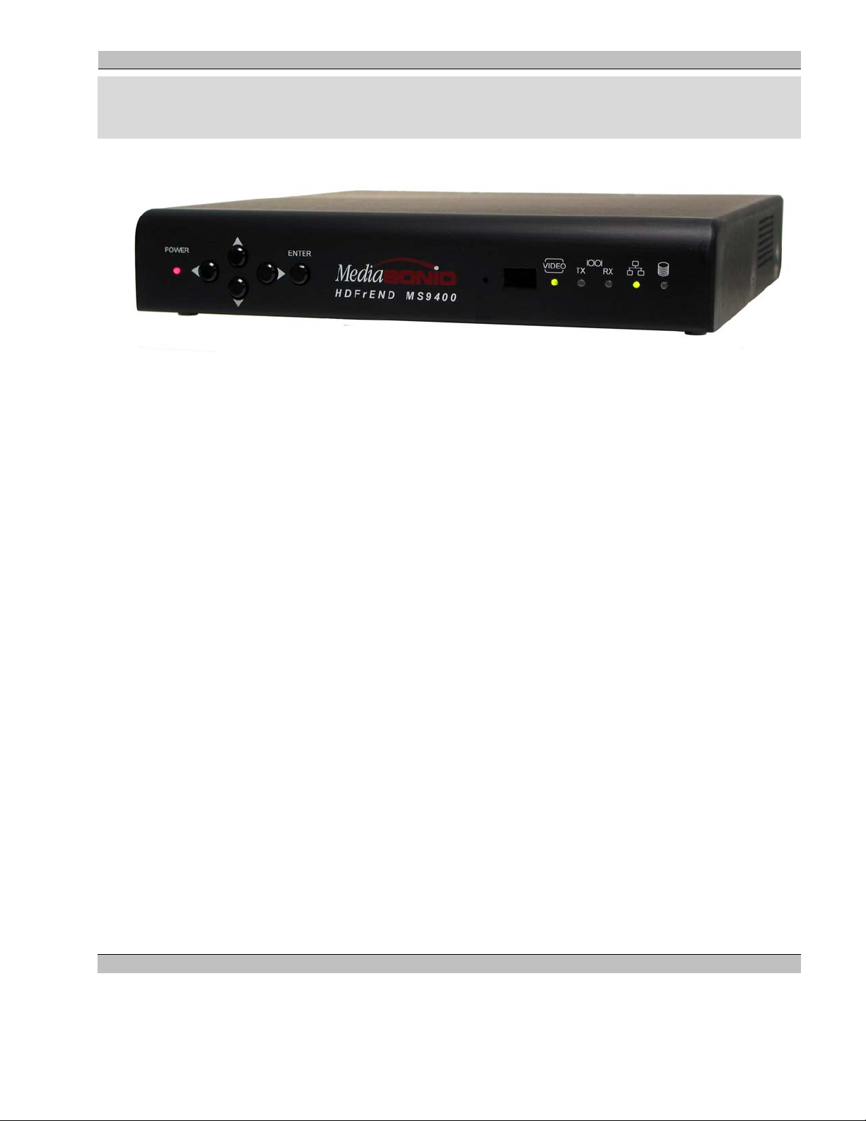
The MediaSonic MS9400 HD FrEND is a simple to use, High Definition (HD) Video Player Appliance that
supports numerous video formats and is designed to facilitate deployment of HD Media Networks in a wide
variety of situations.
Main features:
• Support for 1920 x 1080i, 1280 x 720p and 720 x 576/480p as well as other formats
• Remote management with TCP/IP interface
• Simultaneous HD and SD output
• Composite and S-Video outputs
• Compact size for easy installation close to display devices
• Analog and Digital audio
• Linux OS
• Support for ESCAN and iMediate
• IR Hand-Held Remote Control for easy access to the on-screen menu
• Programmable Function buttons on the IR Remote
• Optional GPIO Interface
9 Rev. 1.54
Page 10
MS9400 HD FrEND User Guide Chapter 1: Introduction
Installation
The MS9400 is designed for use in a variety of situations, the most common being ‘desktop’ use.
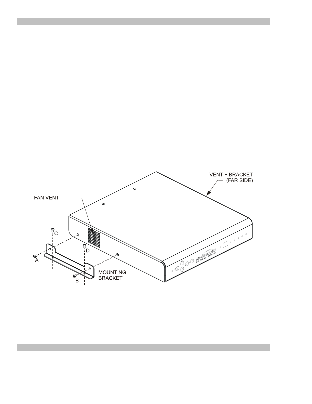
Wall Mounting
Alternatively, the unit may be mounted against a flat horizontal or vertical surface by means of the included
mounting brackets.
NOTE: Ensure that there are no impediments to the inlet and outlet vents on the sides of the case.
NOTE: Prepare the mounting surface to accept 6-32 hardware; the mounting brackets are designed for 6-32
hardware.
1. Remove two screws (A&B in illustration) from each side of the unit.
2. Attach the angle brackets to the sides of the case using two 6-32 x 3/8” screws per side in the same
locations as shown in the following diagram.
3. Position the MS9400 with brackets attached, mark the locations for mounting screw holes (C & D).
4. Remove the MS9400 and drill the mounting holes where marked.
5. Reposition the MS9400 and secure to the mounting holes.
6. Make the necessary connections to the rear of the MS9400.
10 Rev. 1.54
Page 11
MS9400 HD FrEND User Guide Chapter 2: Player Controls and Se t-U p
Chapter 2: Player Controls and Set-Up
Front Panel
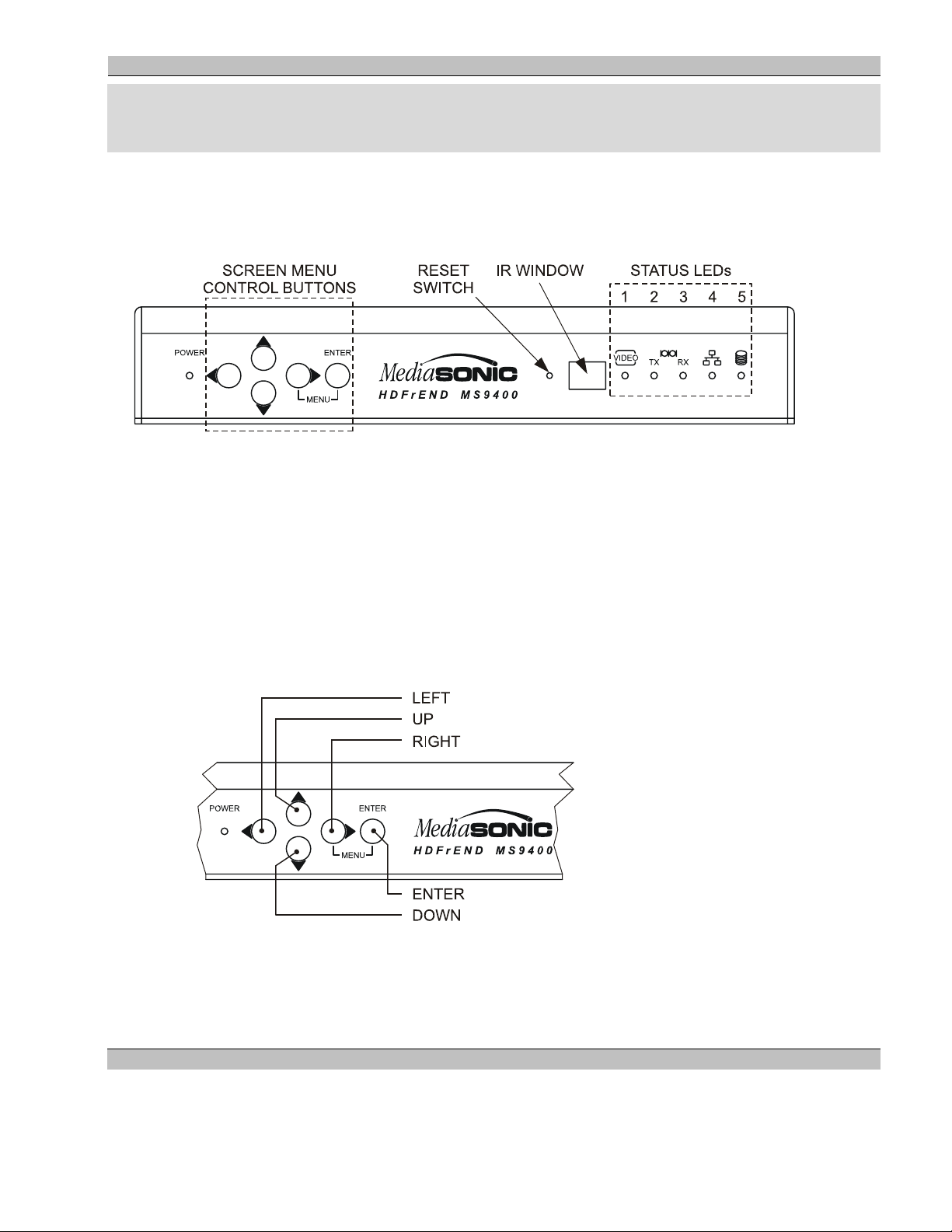
The following diagram illustrates the MS9400 front panel layout:
Front Panel Controls
The front panel is equipped with a number of user interface and monitoring features; from left to right they are:
• POWER LED – Glows when the main power switch (back panel) is ON.
• SCREEN MENU CONTROL BUTTONS:
Press the Right (>) and Enter buttons simultaneously to turn the screen menu On or Off.
Press a particular button (direction of movement is indicated by the arrow next to it) to move the cursor
on the screen.
Press the ENTER button to make a selection.
• RESET – Press this switch to reset the MS9400. The switch is recessed behind the front panel to prevent
inadvertent activation. Use a paper clip to access the switch through the hole.
• IR WINDOW – Allows remote control from an IR source (wireless hand-held or wired)
11 Rev. 1.54
Page 12
MS9400 HD FrEND User Guide Chapter 2: Player Controls and Se t-U p
• STATUS LEDs (Refer to top diagram) - Indicate:
1. VIDEO active
2. RS232 TX (Transmit) active
3. RS232 RX (Receive) active
4. Network connected
5. Hard Disk active
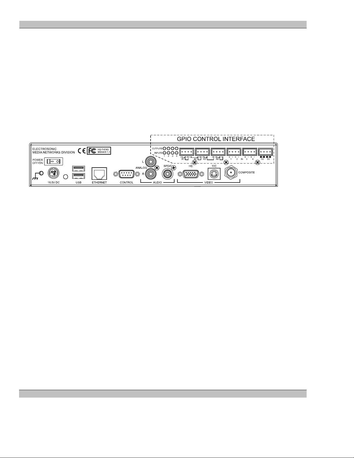
Rear Panel Interface
The following diagram illustrates the MS9400 rear panel layout:
The rear panel interface is as follows (from left to right):
• POWER OFF/ON - Main power switch.
• Power input jack (18.5VDC). This is accepts a locking plug from the outboard power supply adapter.
• USB – (Future) These ports facilitate data transfer to the MS9400 from portable data storage devices;
also, the user may connect a USB keyboard for accessing player functions.
• ETHERNET – Access the LAN for TCP/IP control capability and data transfer.
• CONTROL – RS232 I/O port for local computer control.
• AUDIO – Stereo ANALOG Left, Right and/or SPDIF 5.1 audio outputs.
• VIDEO, HD – High Definition Video output. (Component Video)
Connection for a High Definition Video display device.
• VIDEO, Y/C – Y/C video output (S-Video)
• VIDEO, COMPOSITE – Composite video output.
NOTE: Any of the video outputs may be used. Resolution and image quality will vary depending upon
the output selected.
• CONTROL INTERFACE Refer to Chapter 7: Using the GPIO Control Interface.
12 Rev. 1.54
Page 13
MS9400 HD FrEND User Guide Chapter 2: Player Controls and Se t-U p
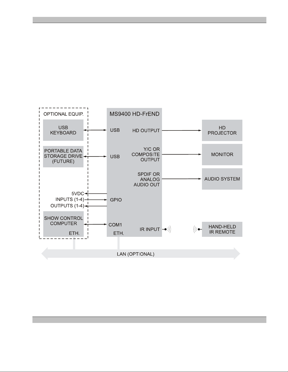
System Configuration
Use the HD FrEND in simple stand-alone configurations consisting of the player, an HD display and an audio
system, or in more complex network integrated systems.
The following diagram illustrates a generic system utilizing an HD FrEND player. Your actual system
configuration may be different but will be some variant of that shown. The Show Control Computer is only
necessary when using the HD FrEND in a network (LAN) controlled system, or locally controlled through the
RS232 port.
Refer to Chapter 5: Remote Control Protocol, for more details.
MS9400 Generic System Interface diagram:
13 Rev. 1.54
Page 14
MS9400 HD FrEND User Guide Chapter 2: Player Controls and Se t-U p
“Quick Start”
Assuming correct connection of the MS9400 into a display system, perform system steps 1-3 below to turn on the
player:
1. Turn ‘on’ the main POWER OFF/ON switch at the rear of the player (the power LED on the front panel
will glow). NOTE: Should the power Led not illuminate, verify that the power supply is securely
connected then toggle the power switch between OFF/ON.
2. The Hard Drive Led will flash during initialization (this could take up to 1 minute).
3. Once initialization is finished, a pre-loaded file will begin playing. Video will appear on the display and
audio will be heard from the speakers - this confirms the correct system ‘hook-up’. Default play mode is
‘Loop Play’; the file will continue playing repeatedly until the MS9400 receives a ‘Stop’ command from
the remote control.
To play a different Test File:
The user may wish to view other Test File(s) present on the MS9400:
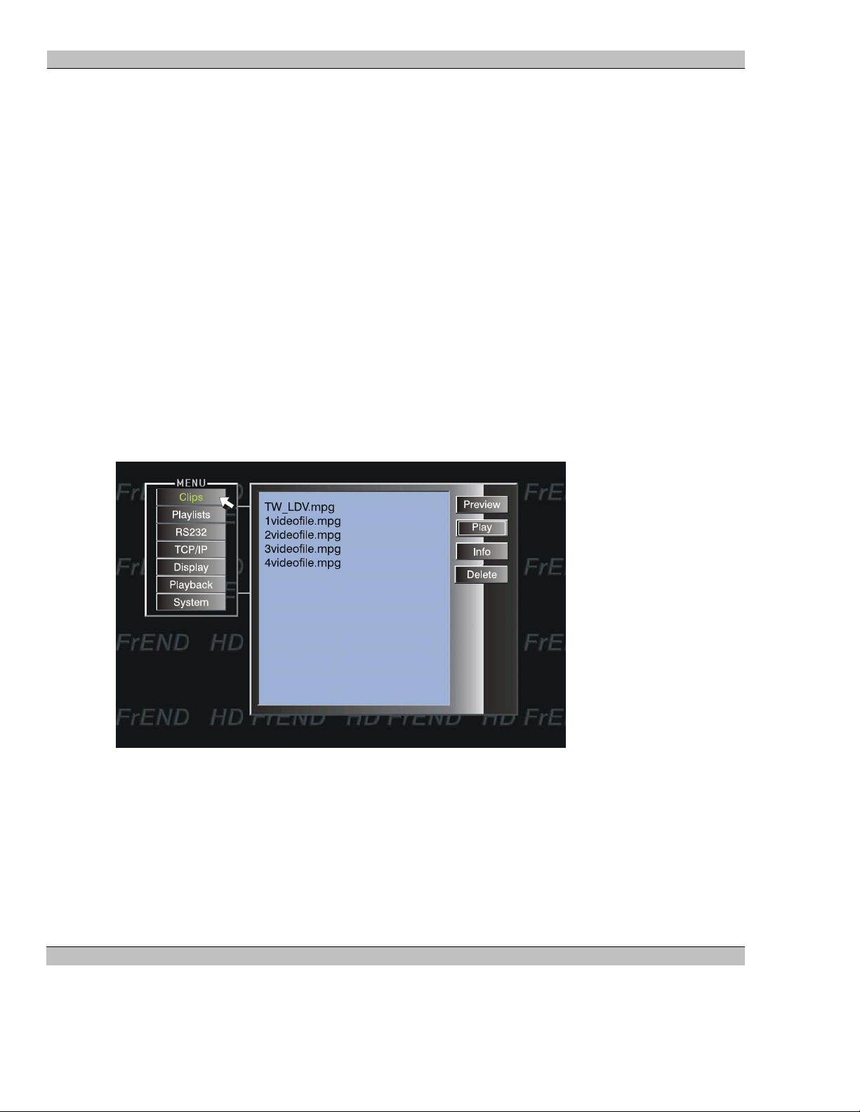
1. Press the <MENU> button on the remote control (having first, pressed the <PC> or <MS9400> button).
The on-screen menu appears with a list of the Test Files pre-loaded in the Clips folder on the MS9400:
2. Use the joystick to navigate to the desired file. Press <SELECT> on your hand-held remote control (the
file will be highlighted).
3. Navigate to and Click <Play> on the menu; the chosen file will begin loop-play until it receives a stop
command.
4. Press the <STOP> button on your hand-held remote control. The player display will go black.
5. Press <MENU> to return to the main menu
Refer to Chapter 4: Playing Files for more information
14 Rev. 1.54
Page 15
MS9400 HD FrEND User Guide Chapter 2: Player Controls and Se t-U p
Hand-held IR remote control
Use the hand-held IR remote control to access the HD FrEND’s on-screen user interface during player set-up or to
control the player manually.
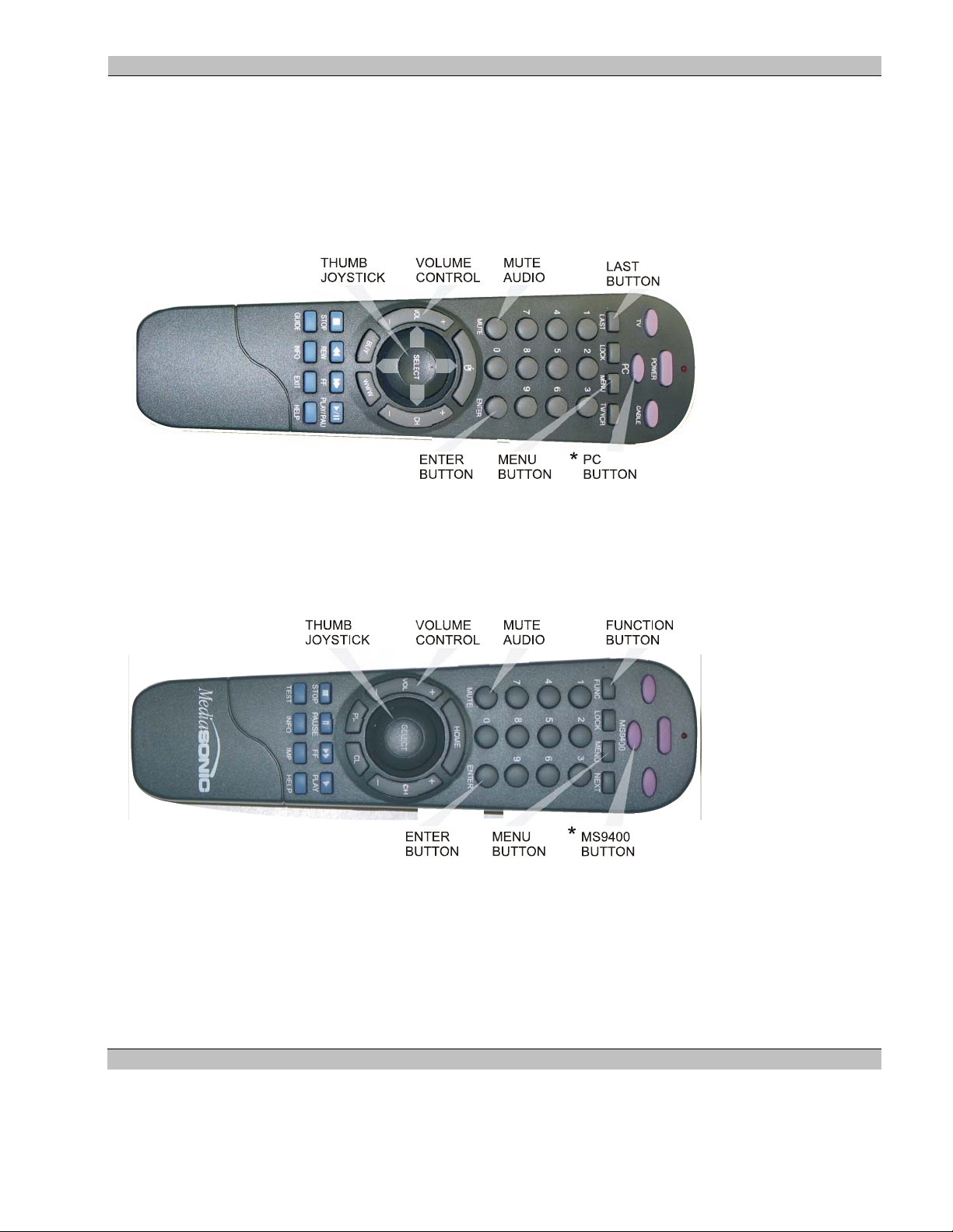
IR Remote Control Version 1
The Remote Control provided with initial versions of the MS9400 is shown in the image below:
*NOTE: Press the light-purple <PC> button on the remote control before you begin set-up. This action
ensures that the remote is configured for controlling the MS 9400.
IR Remote Control Version 2
The Remote Control provided with current versions of the MS9400 is shown in the image below:
*NOTE: Press the light-purple <MS9400> button on the remote control before you begin set-up. This action
ensures that the remote is configured for controlling the MS 9400.
15 Rev. 1.54
Page 16

MS9400 HD FrEND User Guide Chapter 2: Player Controls and Se t-U p
IR Remote Control Features
NOTE: Button functions on the two remote control versions are identical; only the button legends are different.
Press the <MENU> button to activate the on-screen menu.
Navigate the MS9400 screen menus by using the thumb-joystick on the hand-held remote control:
• Rock the joystick left/right/up/down as needed to move the cursor around the menu as you would a
mouse on a computer screen
• Press <SELECT> on the joystick to “Click” on the appropriate screen menu buttons.
• Press <MENU> to exit the screen menu at any time.
The <FUNC>/<LAST> button
Press the FUNC button (Version 2) or the LAST button (Version 1) and then any of buttons 1 through 9 on the
keypad to implement a number of preset control features (macros). These macros are stored as ‘FX.mac’ files in
the /media folder on the HD FrEND.
FUNC/LAST +1: Sets video output 1 mode to RGBHV
FUNC/LAST +2: Sets video output 1 mode to YPrPb
FUNC/LAST +3: Sets video output 1 resolution to 1920 x 1080i 59
FUNC/LAST +4: Sets video output 1 resolution to 1280 x 720p 59
FUNC/LAST +5: Sets video output 1 resolution to 720 x 480p 59
FUNC/LAST +6: Sets video output 1 resolution to 1920 x 1080i 50
FUNC/LAST +7: Sets video output 1 resolution to 1280 x 720p 50
FUNC/LAST +8: Sets video output 1 resolution to 720 x 576p 50
FUNC/LAST +9: Load Playlist 1 and play once
The above combinations may be customized (re-programmed) by the user to activate any of the MS9400’s control
commands (from the MS9400 Control Protocol).
NOTE: In the event that you should select a video output format that is not supported by the monit or i n use - the
screen will go black and you will lose the menu display.
To ‘reset’ the menu display i.e. return to the default video output mode (1080i29, RGBHV), press FUNC/LAST
then ‘3’ on the remote and the menu display will re-appear.
Refer to the section ‘Configuration, Display’ later in this chapter for more information on display formats
supported by the MS9400.
Refer to Chapter 7: Using the GPIO Interface for more information on customization of the ‘FX.mac’ files.
16 Rev. 1.54
Page 17

MS9400 HD FrEND User Guide Chapter 2: Player Controls and Se t-U p
Hand-Held IR Remote Control Button functions:
BUTTON
(Version 2)
<TV> N/A
<POWER> N/A
<CABLE> N/A
<MS9400> <PC> Sets the Remote in HD FrEND control mode.
<FUNC> <LAST> Use in conjunction with numerical buttons to access factory presets.
<LOCK> <LOCK> Press this button to prevent access to the number buttons on the IR.
<MENU> <MENU> Toggle the Screen-Menu ON/OFF
<NEXT> <TV/VCR> (Future) Skip to the next Clip in a Playlist
<1-0> <1-0> Numeric Buttons. Use these buttons with the <LAST> button to access factory
<MUTE> <MUTE> Turn off the Audio output
<ENTER> <ENTER> (Future)
<HOME> <MOUSE> (Future) Skip to the first Clip in a Playlist
<-VOL+> <-VOL+> Adjust Audio Output levels
<SELECT> <SELECT> Select an option and/or initiate an action from the Screen-Menu
BUTTON
(Version 1)
FUNCTION
presets
<-CH+> <-CH+> (Future) Scroll the media Clips list
<PL> <BUY> (Future) Open the Screen-menu on the Playlist page
<CL> <WWW> (Future) Open the Screen-Menu on the Clips page
<STOP> <STOP> Stop a file during Playback (the display will go to black)
<PAUSE> <REW> Pause during Playback (the frame will freeze on the display)
<FF> <FF> (Future) Fast-Forward to a new location in a file during Playback
<PLAY> <PLA/PAU> Play a file.
<TEST> <GUIDE> (Future) A Test-Pattern Clip appears on the display
<INFO> <INFO> Display Information about the Hard Drive usage
<IMP> <EXIT> (Future) Import data from a USB Drive
<HELP> <HELP> (Future)
17 Rev. 1.54
Page 18
MS9400 HD FrEND User Guide Chapter 2: Player Controls and Se t-U p
Configuration
Assuming correct connection of the MS9400 into a display system, perform system steps 1-3 below (same as in
“Quick-Start”) to turn on the player and access the configuration menus:
1. Turn on the main POWER OFF/ON switch at the rear of the player (the power LED on the front panel
will glow). NOTE: Should the power Led not illuminate, toggle the power switch between OFF/ON.
2. The Hard Drive Led will flash whilst the MS9400 is completing its initialization. This could take up to 30
seconds. Once the hard drive Led has stopped flashing the unit is ready for configuration.
3. Press the <MENU> button on the remote control (having first, pressed the <PC> button). The on-screen
menu appears:
The up-coming sections give information on how to the edit the configuration settings within the MENU.
NOTE: You may wish to press the <INFO> button on your Remote Control to display:
System Info: Disk Capacity and Disk space in use
Or, Select a File (.mpg) and press the ‘Info’ button on the Screen-Menu to display:
System Info: Disk Capacity, Disk space in use.
File Info: File name and PID information.
Check this data before file transfer to avoid exceeding the Hard Disk capacity.
NOTE: The HD FrEND Serial and Software Version Numbers are displayed at the top of the System Display.
Refer to the section ‘System’ later in this Chapter.
18 Rev. 1.54
Page 19
MS9400 HD FrEND User Guide Chapter 2: Player Controls and Se t-U p
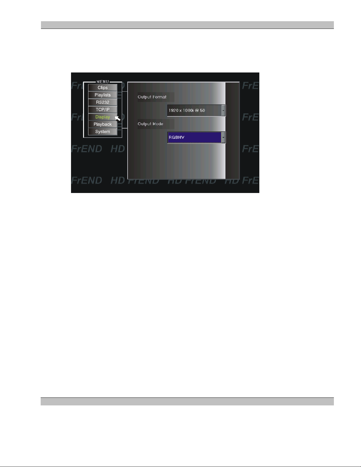
Display
Navigate to and click on the Display menu button. The following screen appears:
Click the scroll button in the property window you wish to edit and choose the output mode that matches your
display from the available options:
• Output Mode:
1920 x 1080i @ 50 (Interlace).
1920 x 1080i @ 59.94 (Interlace). This is the Default output Mode.
1920 x 1080i @ 60 (Interlace).
1280 x 720p @ 50 (Progressive).
1280 x 720p @ 59.94 (Progressive).
1280 x 720p @ 60.00 (Progressive).
720 x 480p @ 59.94 (Progressive).
720 x 480LB @59.94 “Letterbox”, progressive.
720 x 576p @ 50 (Progressive).
720 x 576LB @ 50 “Letterbox”, progressive.
• Output Format: Choose between RGBHV and YprPb. RGBHV is the Default output format.
NOTE: In the event that you should select a video output format that is not supported by the monit or i n use - the
screen will go black and you will lose the menu display.
To ‘reset’ the menu display, i.e. return to the default video output mode (1080i29, RGBHV), press LAST then ‘3’
on the remote and the menu display will re-appear.
19 Rev. 1.54
Page 20
MS9400 HD FrEND User Guide Chapter 2: Player Controls and Se t-U p
Refer to the section ‘Handheld Remote’ Control earlier in this chapter for more information on the IR remote
control buttons.
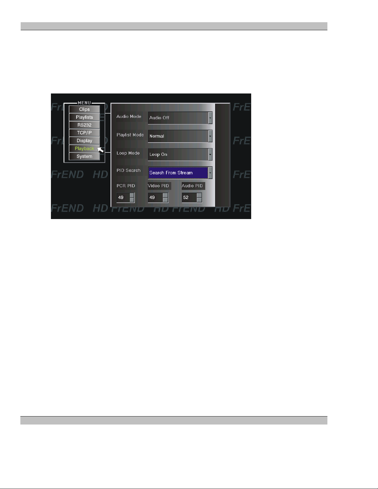
Playback
Navigate to and click on the Playback menu button. The following screen appears:
Click the scroll button in any property window and choose from the available options:
• Audio Mode options are:
Audio Off – No Audio output.
Audio On – Analog and Digital Audio outputs active.
NOTE: These settings do not affect a file during playback. To mute audio output during
playback use the MUTE button on the IR Hand Control.
• Playlist Mode options are:
Normal - Use this setting to allow the HD FrEND to process a Playlist comprised of
files with differing PIDs (there will be a slight delay between the end of one file and the
beginning of the next).
Smooth Transition – Use this setting to smoothly transition between files in a Playlist
comprised of MPEG files having the same PID (recommended).
NOTE: Playlist Mode options may be set remotely if required.
Refer to Chapter 6: Remote Control Protocols for more information.
• Loop Mode options are:
Loop On – File or Playlist plays continuously
Loop Off – File or Playlist plays through once and stops
20 Rev. 1.54
Page 21
MS9400 HD FrEND User Guide Chapter 2: Player Controls and Se t-U p
• PID Search options are:
User Define – When PID is known, select User Define and use the scroll bars in the
windows at the bottom of the display to enter the necessary PIDs. PID information must
match that of the files in use; PIDs are set during file encoding process.
Read From Index File – PIDs are read from a pre-written Index File
Search From Stream – PIDs are read directly from the video file; this process will take
a certain amount of time.
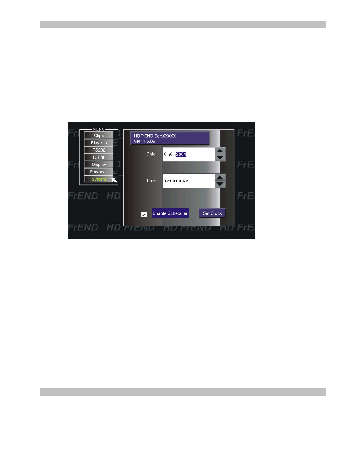
System
Navigate to and click on the System menu button. The following screen appears:
NOTE: The HD FrEND Serial Number and Software Version Number is displayed at the top of the System
Display page.
These settings are necessary for synchronization of the MS9400 to the calendar/clock in a central control system;
such as when using in a network controlled by ESCAN and for running the Event Scheduler.
• Date – Set the Day/Month/Year
• Time – Set the clock to Hours:Minutes:Seconds
• Enable Scheduler – Check/Uncheck box
1. Navigate the windows with the joystick and press <SELECT> to highlight the segment you wish to edit
2. Click on the Up/Down scroll to change the values in the respective windows.
3. Click the Set Clock button when complete
4. Click the Enable Scheduler check box to turn the Serial Port Event Scheduler On or Off. If you un-check
the box any Scheduler Script that may be running on the MS9400 will stop. When not using the Event
Scheduler ignore this setting.
Refer to Chapter 4: RS232 (Serial) Port Event Scheduler for information on how to use the scheduler feature.
Refer to Chapter 6: Remote Control Protocols for command syntax.
21 Rev. 1.54
Page 22
MS9400 HD FrEND User Guide Chapter 2: Player Controls and Se t-U p
NOTE: When an external ‘RunScheduler’ command is received by the MS9400 the check box display will change
only after toggling the menu OFF and back to ON.
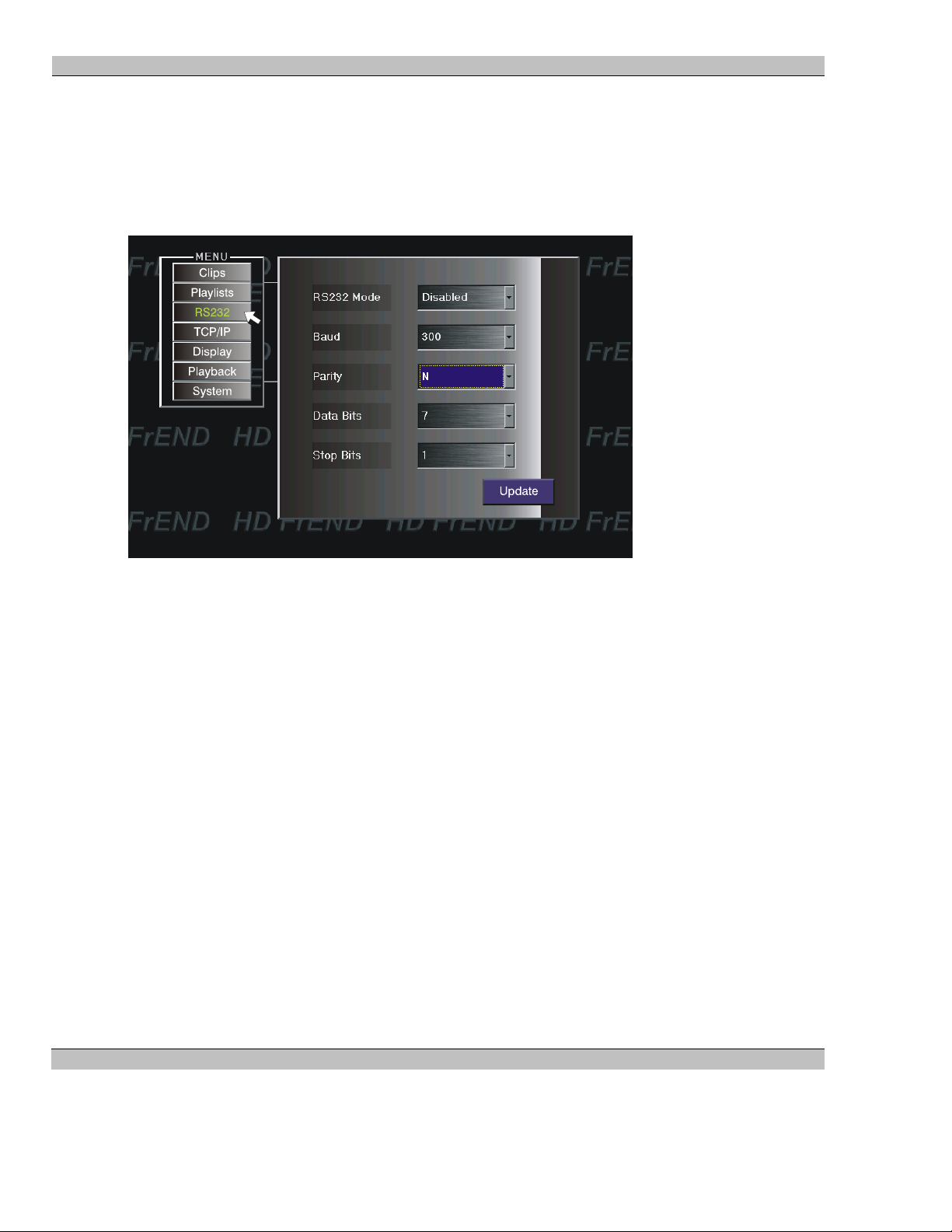
Remote Control – RS232
Navigate to and click on the RS232 menu button. The following screen appears:
This menu allows setup of the MS9400 Comm Port for remote control with ESCAN or other control application.
Click the scroll button adjacent to each window and highlight the necessary value. Click the value to select.
RS232 options are:
• RS232 Mode – Choose Disabled, Control, Pass Through, or LCD
Disabled – Use this setting to prevent remote control access to the MS9400
Control - Use this setting when the MS9400 is to be controlled remotely with ESCAN.
Pass Through - Use the “Pass Through” setting to control another device such as a video projector
(RS232) from the MS9400 with ESCAN or some other control system.
NOTE: When using the Pass Through setting ensure that the Baud Rate, Parity, Data Bits and Stop Bit are
set to match the device being controlled. Also, in your remote control program, set the IP Port Number to
4001 and the IP address to that of the HD FrEND in use. In Pass Through mode any TCP/IP control string
appearing on port 4001of the HD FrEND is passed to the RS232 port.
LCD – Factory use only.
• Baud Rate – Choose from 300, 600, 1200, 4800, 9600, 19200, 38400, 57600 and 115200
• Parity – Choose from Null, Even, and Odd
• Data Bits – Choose between 7 and 8
• Stop Bit – Choose between 1 and 2
22 Rev. 1.54
Page 23
MS9400 HD FrEND User Guide Chapter 2: Player Controls and Se t-U p
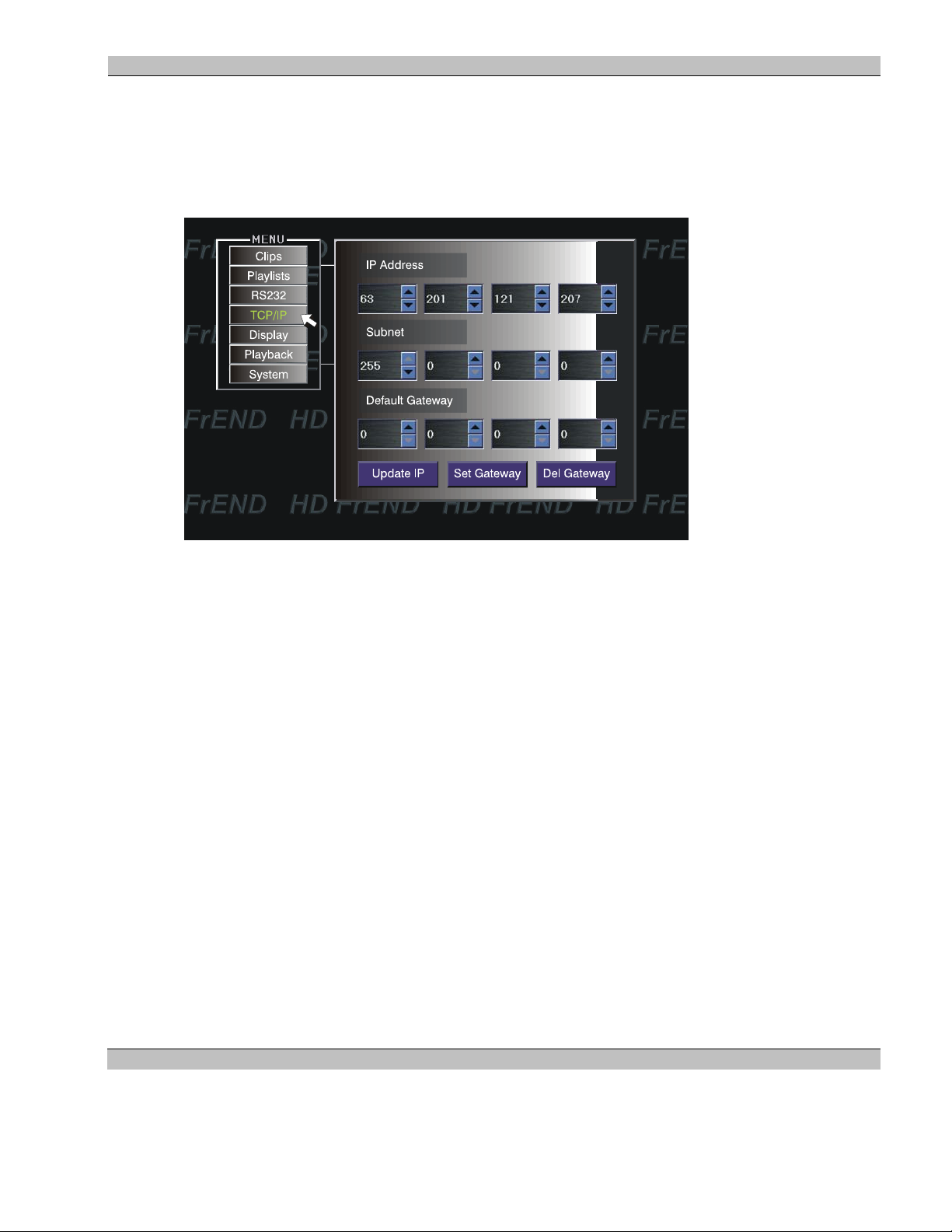
• Update – Click to ‘set’ your changes to the parameters selected.
Remote Control – TCP/IP
Navigate to and click on the TCP/IP menu button. The following screen appears:
This menu allows the MS9400 to be set-up for use in a Network.
NOTE: Numbers shown in the image above are illustrative only - your actual display will be different.
• IP Address - Click on the scroll buttons to adjust the IP numbers as required for your network control
system.
• Subnet - Click on the scroll buttons to adjust the Subnet settings as required.
• Default Gateway – Click on the scroll buttons to set the Default Gateway – your network administrator
can give you the required address.
• Update IP – Click to ‘set’ your IP to the parameters selected.
• Set Gateway – Click to ‘set’ the Default Gateway address
• Del Gateway – Click to disable the HD FrEND Default Gateway.
NOTE: This would be a good time to make a note of the MS9400’s IP address as this information will be required
for transferring MPEG files to the MS9400 with an FTP application (refer to following chapter).
Audio Volume control
Audio Volume may only be adjusted during playback:
Use the <VOL +/-> button to the left of the <SELECT> joystick on the hand-held remote control.
23 Rev. 1.54
Page 24
MS9400 HD FrEND User Guide Chapter 3: Data Transfer
Chapter 3: Data Transfer
Loading MPEG (.mpg) data files:
MPEG encoded HD or SD video clips (MPEG data) must be loaded on to the MS9400’s hard disk in order to be
played (sent to a display device).
Transfer all video files to the default folder in the MS9400 (a default test MPEG file is included with the
MS9400); this is the /media folder.
The user has two methods available for loading MPEG data into the MS9400:
• ETHERNET port on the back panel – Connect the MS9400 to your LAN and transfer MPEG data
from your file storage system (or another computer) with any FTP application.
• (Future) USB interface on the back panel – Connect the MS9400 to another computer or to a portable
drive and transfer files to the MS9400
Use the FTP application of your choice to up-load MPEG (.mpg) files stored on a “local computer” to the
MS9400. Follow the directions given with the specific application for transferring data between computers.
For the purpose of example we will describe two methods for file transfer:
1. The DOS command window
2. Internet Explorer
Perform these procedures with any Windows based PC.
The MS9400 “remote computer” and the computer containing video files for transfer (“local computer”), must be
connected to a network.
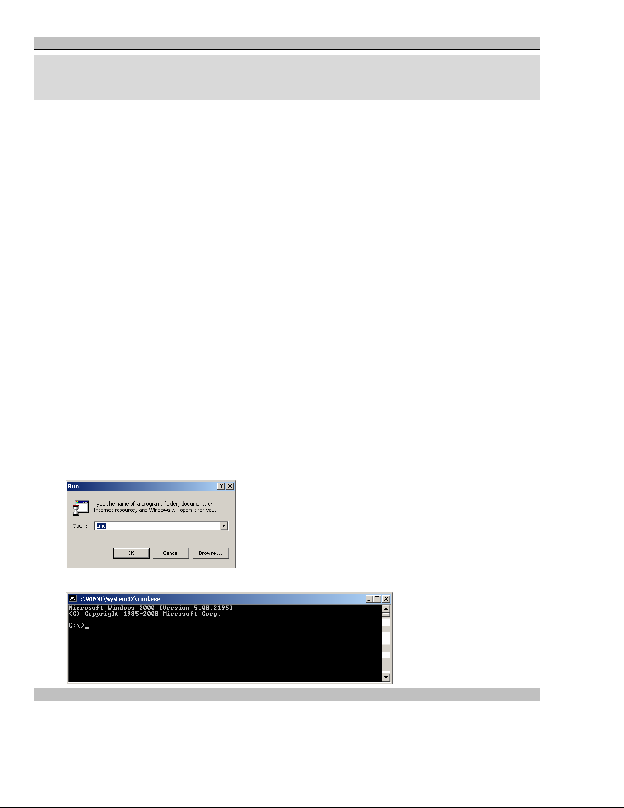
To Up-Load data with the DOS window:
1. Select Start/Run/ and type: cmd as shown; click OK
The following should appear:
24 Rev. 1.54
Page 25
MS9400 HD FrEND User Guide Chapter 3: Data Transfer
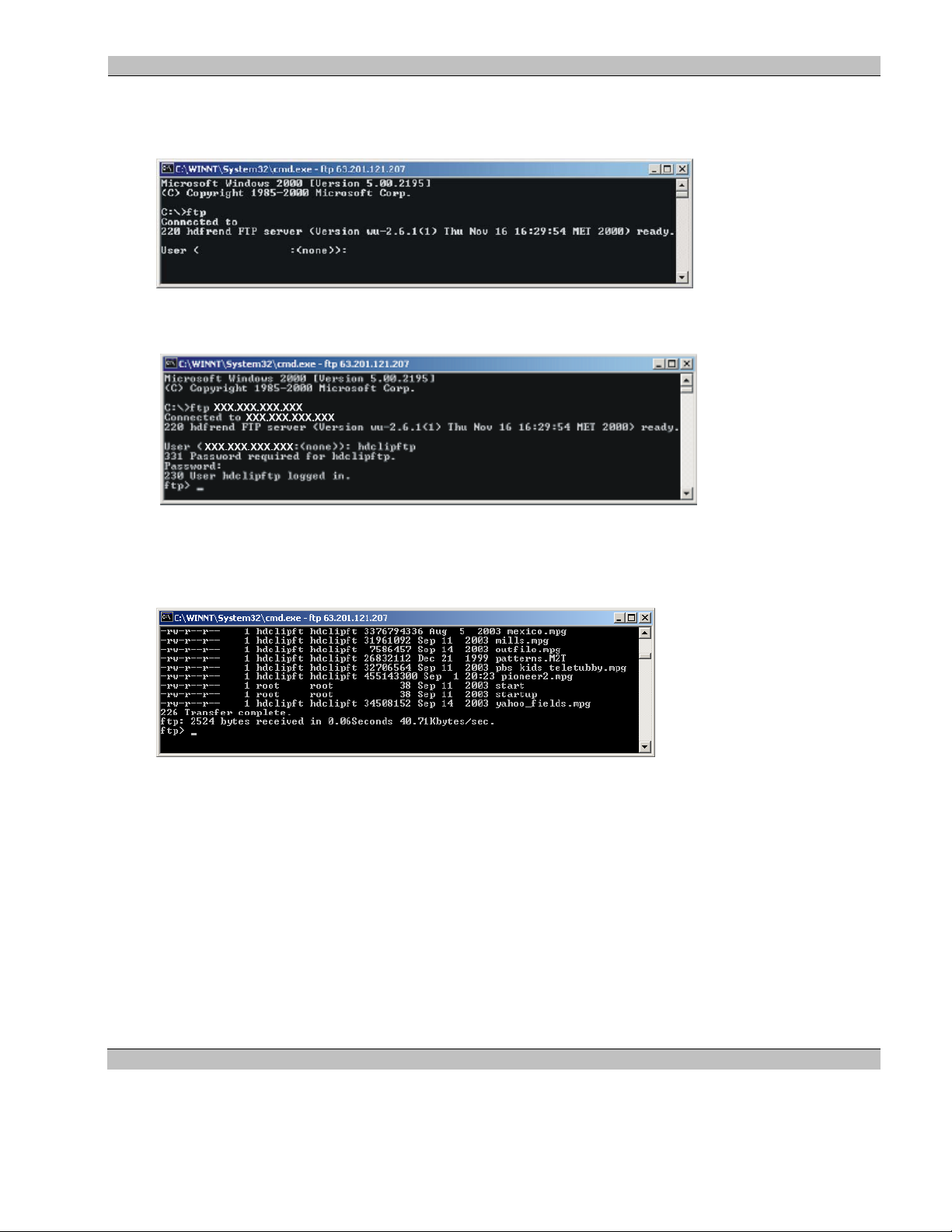
2. At the command prompt enter: ftp XXX.XXX.XXX. X XX (where X…X is the IP address of the MS9400
from the ‘System Options’ menu: Set IP (Step 8 in the previous chapter). Press Enter/Return.
The following will be displayed as soon as the local computer is connected to the MS9400:
XXX.XXX.XXX.XXX
XXX.XXX.XXX.XXX
XXX.XXX.XXX.XXX
3. Enter the User Name: hdclipftp (case sensitive), press Enter/Return when prompted.
4. Enter your password: mediasonic (case sensitive), press Enter/Return when prompted.
5. IMPORTANT! Type binary in the command line and press enter/return. This ensures that data is
transferred to the MS9400 correctly.
6. Type: dir in the command line, press Enter/Return. The application will display the MS9400 server file
/media folder:
7. Type: put path\filename and press Enter/Return to send a file from the local computer to the MS9400.
NOTE: MPEG video file sizes may be very large. The time taken to up-load will be dependent on the file
size as well as the bandwidth of your network connection. Check for the ‘Transfer Complete’ message as
shown above to ensure that your files have completely transferred to the MS9400 before trying to play
them.
8. Type: quit or bye to exit.
9. Close the DOS window.
Having transferred your program material to the MS9400 you can now play your video files safely.
Refer to Chapter 4: Playing Files for more information.
25 Rev. 1.54
Page 26

MS9400 HD FrEND User Guide Chapter 3: Data Transfer
To Delete a file from the MS9400 using DOS
If necessary you may remove files from the MS9400:
1. Open a DOS window and log on to the MS9400 as shown above.
2. Type: del filename enter/return in the command line.
The file will be removed from the /media folder on the MS9400.
To Up-Load data with Internet Explorer
1. Open Internet Explorer on the local computer.
In the Address line, as shown above, type the IP address for your MS9400 (from System Options: Set IP –
Chapter 2, Step 8), press Enter/Return.
Press Enter/Return; the following Login dialog box will be displayed:
2.
Enter the User Name: hdclipftp (case sensitive)
Enter the Password: mediasonic (case sensitive).
Click Login. The MS9400 file /media folder is displayed:
26 Rev. 1.54
Page 27

MS9400 HD FrEND User Guide Chapter 3: Data Transfer
3. Open a file manager window by clicking My Computer on the desktop.
4. Select the file(s) you wish to transfer and drag/drop from the My Computer window (local computer) to
the Internet Explorer window (MS9400).
NOTE: MPEG video file sizes may be very large. The time taken to up-load will be dependent on the file size as
well as the bandwidth of the network connection. Ensure that the files have completely transferred to the MS9400
before trying to play them.
Having transferred the program material to the MS9400 you are now ready to play the files.
Refer to Chapter 4: Playing Files.
To Delete a file from the MS9400 using Internet Explorer
If necessary you may remove files from the MS9400:
1. Open Internet Explorer and log on to the MS9400 as shown above
2. Select the file you wish to remove from the list in the window
3. Right click the file and select Delete from the menu. The file will be removed from the /media folder
on the MS9400.
27 Rev. 1.54
Page 28

MS9400 HD FrEND User Guide Chapter 4: RS232 (Serial) Port Event Scheduler
Chapter 4: RS232 (Serial) Port Event Scheduler
The MS9400 HDFrend has the built in capability to run a simple scheduler that can issue serial commands out of
the RS232 port relative to the time of day. This feature gives the MS9400 the ability to act as a local controller for
a simple playback system.
The scheduler operates by running a script file and comparing the entries in this file to the current settings of the
MS9400’s real time clock (RTC); when a match occurs the corresponding text string is transmitted on the RS232
port.
NOTE: If the MS9400 loses power for more than 24 hours the user must reset the RTC on the MS9400 (System
page).
Event Script
The Event Script file name is case sensitive and must be entered exactly as shown: Events.sch
The Events.sch file must be located in the /media/ folder on the MS9400 and will be processed by the MS9400 as
follows:
1. On system power up.
2. When the real time clock transitions through midnight.
3. If the file Events.sch file is modified either by the vi* editor or, if a new version of the Events.sch has
been copied to the MS9400 using ftp. *Linux Text Editor.
4. If the Event Scheduler check-box status is changed.
NOTE: Ensure that the MS9400 menu ‘Enable Scheduler’ check-box is correctly set (System page):
Checked = Event Scheduler will run if an Events.sch file is present
Un-checked = Event Scheduler will not run if an Events.sch file is present.
Event Script Format
Refer to the descriptions of each command line given immediately following the Event Script Format below.
<Event>
<StartDate>##/##/####</StartDate>
<EndDate>##/##/####</EndDate>
<DayOfWeek>#,#,#,#,#,#,#</DayOfWeek>
<EventTime>##:##:##</EventTime>
<CommandString>…[#]</CommandString>
</Event>
28 Rev. 1.54
Page 29

MS9400 HD FrEND User Guide Chapter 4: RS232 (Serial) Port Event Scheduler
<Event>
…
</Event>
Using a Text Editor of your choice, enter command lines as illustrated in the Event Script Format above.
NOTE: Characters are not case sensitive.
Events
The script file can contain more than one event.
Each event must be bracketed with the <Event> </Event> tags
Start Date
The Start Date uses the following format: Month/Day/Year.
The start date must be bracketed with the <StartDate> </StartDate> tags.
End Date
The End Date uses the following format: Month/Day/Year.
The end date must be bracketed with the <EndDate> </EndDate> tags.
Day of Week
The Day of Week contains seven locations (one per day of the week: Sun,Mon,Tue,Wed,Thu,Fri,Sat) separated by
commas. Assign a ‘1’ to the day location for the required event, otherwise assign a ‘0’.
The Day of Week must be bracketed with the < DayofWeek > </ DayofWeek > tags.
Event Time
The Event Time uses the following format: Hour:Minute:Second.
The end date must be bracketed with the <EventTime> </EventTime> tags
Command String
The Command String contains the text string defined by the Remote Control Protocols. To transmit a string out of
the serial port to an external device, use the “outport” protocol.
NOTE: If required by the external device, a terminating character is placed in the [#] sub tag. The scheduler
supports both Line Feed and Carriage Return 0A (LF) and 0D (CR) codes.
The Command String must be bracketed with the < CommandString > </ CommandString > tags.
NOTE: Any of the MS9400 Remote Control Protocol commands may be used in the Command String code line.
For example:
<CommandString>Load Playlist 1 “playlistname”</CommandString>.
Refer to Chapter 6: Remote Control Protocols for a list of supported commands.
29 Rev. 1.54
Page 30

MS9400 HD FrEND User Guide Chapter 4: RS232 (Serial) Port Event Scheduler
Example Script Files
Example 1: Turn Display ON/OFF
Below is an example script file that will switch an LCD panel display ‘ON’ every Monday, Wednesday, and
Friday at 8 AM, and OFF at 9 PM from 07/01/2005 to 07/31/2005.
<Event>
<StartDate>07/01/2005</StartDate>
<EndDate>07/31/2005</EndDate>
<DayOfWeek>0,1,0,1,0,1,0</DayOfWeek>
<EventTime>08:00:00</EventTime>
<CommandString>outport 1 “op ZZ display.power = ON [0D]”</CommandString>
</Event>
<Event>
<StartDate>07/01/2005</StartDate>
<EndDate>07/31/2005</EndDate>
<DateOfWeek>0,1,0,1,0,1,0</DateOfWeek>
<EventTime>21:00:00</EventTime>
<CommandString>outport 1 “op ZZ display.power =OFF [0D]”</CommandString>
</Event>
Example 2: Load and Play a Playlist
Below is an example script file that will load and play (MS9400 command protocol: ‘LoadPlaylist’) a playlist
named ‘yourplaylistname’ every Monday, Wednesday, and Friday at 8 AM.
<Event>
<StartDate>07/01/2005</StartDate>
<EndDate>07/31/2005</EndDate>
<DayOfWeek>0,1,0,1,0,1,0</DayOfWeek>
<EventTime>08:00:00</EventTime>
<CommandString>LoadPlaylist 1 “yourplaylistname”</CommandString>
</Event>
30 Rev. 1.54
Page 31

MS9400 HD FrEND User Guide Chapter 5: Playing Files
Chapter 5: Playing Files
MS9400 in a Stand-alone installation
NOTE: Store all video data files and playlist files in the default folder (/media) of the MS9400.
To play files resident on the MS9400 disk drive:
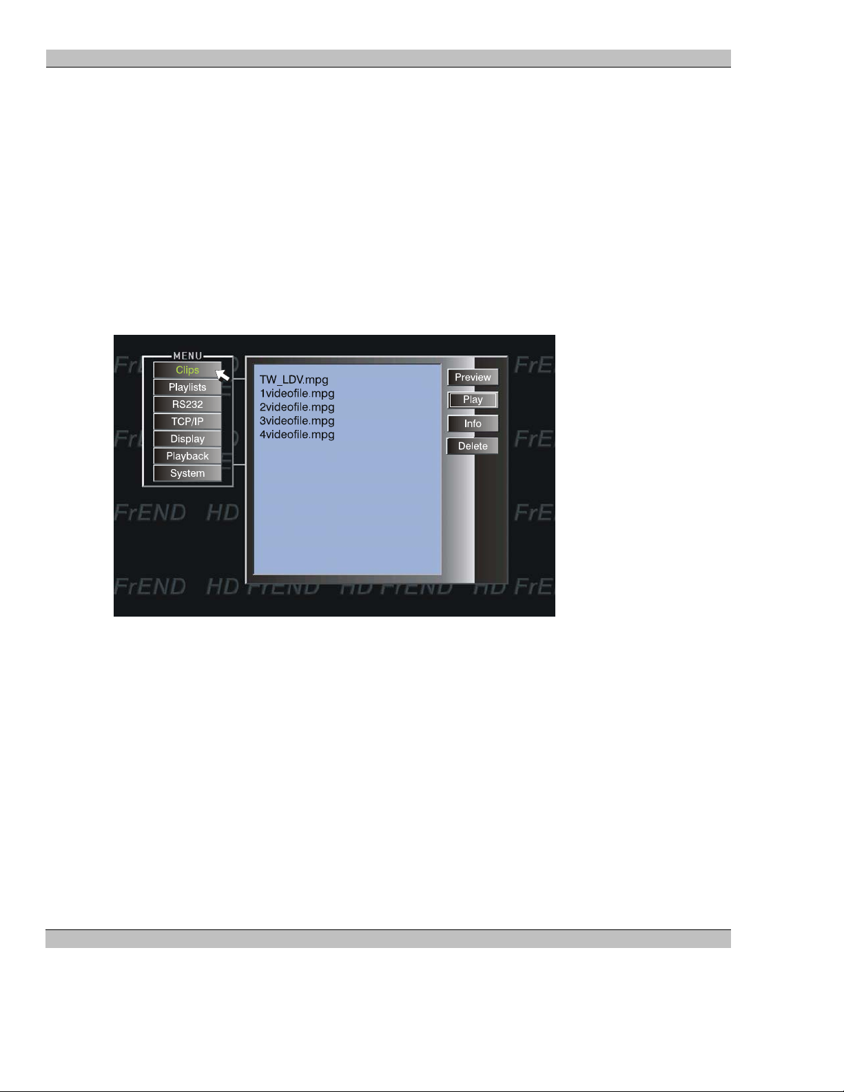
1. Press the <MENU> button on the remote, or, if the menu is already being displayed click on the Clips
button - the HD FrEND Main Menu appears:
The window in the middle of the menu displays a list of all the files available on the player. Any files that
have been transferred to the MS9400 will appear in the Files list.
If the list of files available is too long to fit in the window, a scroll-bar will appear to allow access to
these files.
2. Use the joystick to navigate to the desired file and press <SELECT>, the file will be highlighted
3. Navigate to and Click the <Play> button on the menu; the chosen file will begin loop-play until it receives
a stop command
4. Press the <STOP> button on your hand-held remote control. The player display will go black.
5. Press <MENU> to return to the main menu and select a different file for playback
NOTE: For testing purposes an MPEG “test” clip is included already loaded into the /media folder.
31 Rev. 1.54
Page 32
MS9400 HD FrEND User Guide Chapter 5: Playing Files
Menu access during Playback:
1. Press the <MENU> button to display the MS9400 menu superimposed on the file being played; make
changes to the configuration if necessary.
2. Press <MENU> to close the menu.
Playlists
This feature allows the user to create groups of .mpeg files “Playlists” that will be run in a pre-determined order.
A Playlist may be added to or have files removed, or the whole Playlist deleted and replaced with another.
1. Press the <MENU> button on the remote - the HD FrEND Main Menu appears.
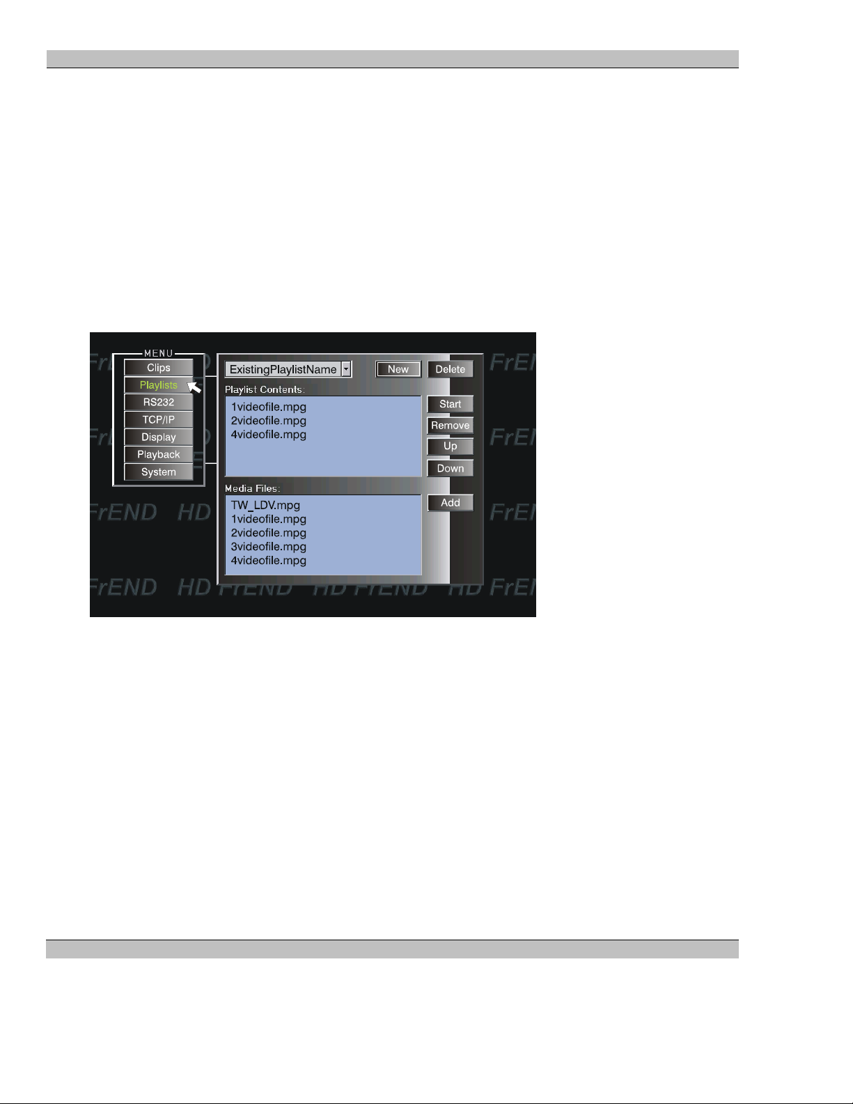
2. Select Playlists, to view the HD FrEND Playlist Menu:
• Playlist Name – Shows all existing Playlists (or none if empty).
New - Click to generate a new Playlist (see Creating a Playlist)
Delete - Click to remove a Playlist
• Playlist Contents – Displays the .mpg files contained in the playlist named in the upper display.
Start - Click to run a Playlist
Remove - Select a file and Click Remove to delete a file from a Playlist
Up - Select a file and Click Up to reorder the file upwards in the Playlist
Down - Select a file and Click Down to reorder the file down in the Playlist
• Media Files – Displays all .mpg files available on the MS9400.
Add - Click to insert a file into a Playlist
32 Rev. 1.54
Page 33
MS9400 HD FrEND User Guide Chapter 5: Playing Files
Creating a Playlist
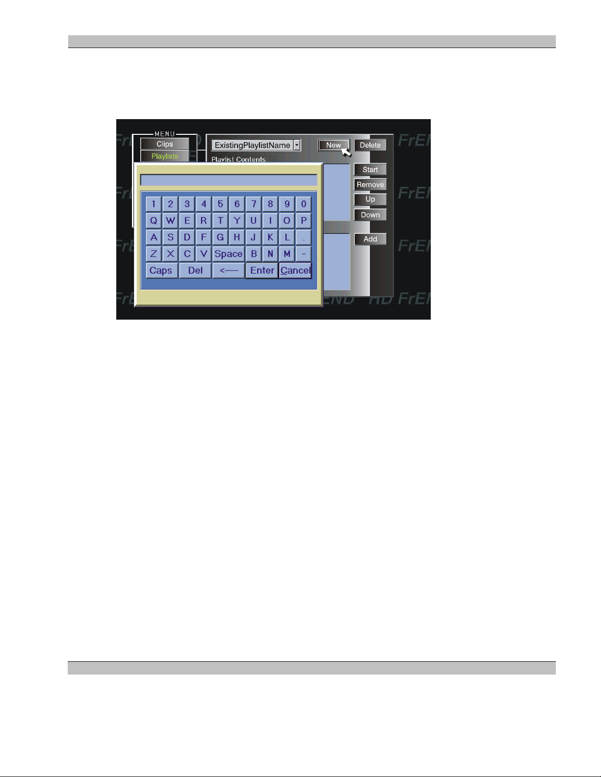
1. Using the thumb-joystick on your hand-held remote control (previously described) click the New button
on the menu. A basic “Keyboard” display appears:
2. “Type in” the Playlist Name by clicking the various characters on the keyboard – as they are selected the
characters appear in the Playlist Name window. When finished click OK and return to the previous menu.
Click Delete and then OK to remove a Playlist from the display.
3. Select the file(s) you wish to add to your playlist and click the Add button. The selected files will be
added to the Playlist and appear in the Playlist Contents window in the order that they are inserted. Select
any unwanted files in the Playlist and click the Remove button to delete them from the Playlist.
4. Click the Start button to begin playing the Playlist. The menu will disappear and the first file in the
Playlist will begin playback.
Playlists created with ESCAN can be named as required by the user and uploaded to the MS9400 using the FTP
procedures outlined in the previous chapter.
NOTE: You may not rename playlists directly on the MS9400. A new playlist must be created and the “old” files
added. The original playlist may be deleted if desired.
Playlists may be also be deleted remotely using the FTP delete procedure described in the previous chapter.
33 Rev. 1.54
Page 34

MS9400 HD FrEND User Guide Chapter 5: Playing Files
Startup Playlist
The MS9400 control software is programmed to look for a “Startup” playlist. If one has been generated the
playlist will begin running automatically anytime the MS9400 is turned on.
To generate a Startup playlist
1. Using any text editor on your PC, open a new text file called startup.lst (All text in this file is case
sensitive).
2. Enter the sequence for each MPEG file to be contained in the list:
MediaPath (enter/return)
MediaFileName (enter/return)
Inpoint<sp>Outpoint (enter/return). Inpoint and Outpoint are set as ‘0’ and ‘-1’ respectively; if any
other settings are required consult Electrosonic.
As an example (using fictional video file names) the startup playlist could be written:
/media
panorama.mpg
0 -1
/media
tinaturns.mpg
0 -1
/media
sunspots.mpg
0 -1
3. Using your FTP application (refer to the previous chapter) up-load the Startup file (startup.lst) to the
/media folder on the MS9400
The Startup playlist will search for the files on the MS9400 and play them in the order defined in the list.
MS9400 in a larger system
Access the control features described above through a LAN system and a sequencing/scheduling application such
as ESCAN by Electrosonic Media Networks Division.
Refer to Chapter 6: Remote Control Protocol, for more information.
Refer to Chapter 7: Using the GPIO Control Interface.
34 Rev. 1.54
Page 35

MS9400 HD FrEND User Guide Chapter 6: Remote Control Protocol
Chapter 6: Remote Control Protocol
Introduction:
This chapter describes a generic control protocol for the MS9400 HD FrEND video playback device (“Player”).
The protocol is a simple ASCII text based control method designed for easy implementation through a TCP/IP
connection or a serial port.
The MS9400 utilizes certain remote control commands drawn from the MediaSonic Remote Control Protocol set.
Users familiar with remote control of other MediaSonic HD Player products will already be aware of much of the
command syntax.
NOTE: When setting up text commands ensure that ‘Port’ is set to 4000.
Example: telnet <IP ADDRESS> <4000>
All commands and responses follow a similar structure as shown below.
KeyWord <parameter> …. <parameter> <terminator>
Many commands require a parameter list; a chapter number, or frame number for example. Parameters are space
separated. In the case where a parameter contains spaces, quotes (“) can be used to bracket the parameter.
The terminator can be a Carriage Return, a Carriage Return & Line Feed, or a NULL (0x00).
Commands are not
Protocol processors should support strings up to 1000 characters. Strings longer than this can be considered
invalid.
If the protocol processor finds an error in the message, it will respond with
error <terminator>
Correctly received messages will respond with either
OK <terminator>
or a message-specific response as illustrated for each command.
Parameter Types
The following parameter types are defined…
<number> - a decimal number.
<frame> - a decimal frame number.
<string> - a textual string. This can optionally be enclosed in quotes if the string contains spaces.
case sensitive.
<timecode> - a timecode in format hh:mm:ss:ff.
<mediapath> - a path designation for media. Using Linux style format e.g. /video/test
35 Rev. 1.54
Page 36

MS9400 HD FrEND User Guide Chapter 6: Remote Control Protocol
<clip> - a media-clip name.
<channel> - a specific channel.
<channel list> - a list of channels or ‘all’ for every channel.
A <channel list> parameter is mandatory for commands that act on specific channels, but will be absent for
generic player commands. Each section below will indicate whether a channel list is required. The channel list is
a “,” (comma) separated list of channels such as the following
1,2,3 - The command will apply to channels 1, 2 and 3.
A special symbol is also defined for all channels
ALL - The command will apply to all channels
NOTE: Channels are numbered starting at 1.
Local Control
Use the hand-held remote or connect a USB computer keyboard directly to the MS9400.
Network Control
Connect the MS9400 to a show-control computer/system running ESCAN or other control application on a LAN.
36 Rev. 1.54
Page 37

MS9400 HD FrEND User Guide Chapter 6: Remote Control Protocol
CONFIGURATION COMMANDS:
GetPlayerType
This command requests the type of player.
The player will respond with
PlayerType <string1> <number>
Where
String1 = A product from the MediaSonic Player Type list below.
Number = software version. The software version will be a numerically increasing version number
Player Type Description
MS9300SD Single channel SD FrEND.
MS9100HD 9100 series based HD players
MS9200HD 9200 series based HD players.
MS9400HD 9400 series based HD players.
GetChannelCount
This command requests the number of channels present on the player.
The player will respond with
ChannelCount <number>
RunScheduler
Syntax: RunScheduler 0 (Stop Event Scheduler) RunScheduler 1 (Run Event Scheduler)
This command enables the Event Scheduler. The ‘System’ menu will display a Check symbol (or not) next to
‘Enable Scheduler’ depending upon its previous state.
The player will respond with
OK
37 Rev. 1.54
Page 38

MS9400 HD FrEND User Guide Chapter 6: Remote Control Protocol
MEDIA MANAGEMENT COMMANDS:
GetMediaTree
This command is used to retrieve the media storage tree from the player. This command doesn’t return a file
listing but just the tree structure.
The player responds with a series of path commands with the following structure. The tree is terminated with an
empty MediaBranch command.
MediaBranch <channel list> <mediapath>
The <channel list> specifies the channels that can use the media. <mediapath> specifies the name of the branch in
a tree format using a unix style format.
NOTE: The MS9400 default file folder is “/media”. All clips must be stored in the /media folder in order to be
accessed by the player software.
The control system will not interpret the string but will pass it back to the player when creating playlists.
The GetMediaTree command essentially performs a left hand depth first traverse of the media tree.
The following exchange shows an example response from the MS9400 player.
MediaBranch 1 “/media”
MediaBranch
GetClips <mediapath>
This command lists the clips available in a MediaBranch (/media folder) passed in the <string> parameter.
The player responds with a series of clip commands with the following structure. The clip list is terminated with
an empty Clip command.
Clip <mediapath> <clip>
Where <string1> contains a branch returned by GetMediaTree, and <string2> is the name of a clip.
The following exchange shows an example response from the player.
Control syntax: GetClips “/media”
Player: Clip “/media” “Videofile_1.mpg”
Player: Clip “/media” “Videofile_2.mpg”
Player: Clip “/media” “Videofile_3.mpg”
Player: …
Player: Clip
38 Rev. 1.54
Page 39

MS9400 HD FrEND User Guide Chapter 6: Remote Control Protocol
PLAYLIST COMMANDS:
The player protocol implements two different techniques for managing playl ists. If the play er responds to th e
“Supports LocalPlaylists” command the player must implement the playlist creation and replay commands. An
additional interface is provided allowing a control system to manage playlists locally.
ClearPlaylist <string>
This command clears all the entries from the playlist identified by <string>.
NOTE: Existing media file and/or playlist names that include spaces must be enclosed with quotes: “pre show”.
The Player will respond with
OK or ERROR
ListAllPlaylists
Returns a list of all the playlists stored in the server.
The player responds with a list of Playlist commands as follows…
Playlist <string1>
Where <string1> identifies a playlist.
The list is terminated with an empty Playlist message.
Example:
Playlist “Pre-Show”
Playlist “Main-Show”
Playlist
AddPlaylist <string1> <mediapath> <clip>
Adds a clip identified by <clip> located in the media path identified by <m ediap at h> to the play list identified by
<string1>. Use this command to add a new Playlist as well as to add clips to an existing Playlist.
The Player will respond with
OK or ERROR
NOTE: Existing media file and/or playlist names that include spaces must be enclosed with quotes: “pre show”.
Example:
AddPlaylist “Pre-Show” “/media” “Intro.mpg”
AddPlaylist “Main-Show” “/media” “Main attraction.mpg”
The control system doesn’t need to terminate the playlist creation commands since the functionality is implied in
the command.
39 Rev. 1.54
Page 40

MS9400 HD FrEND User Guide Chapter 6: Remote Control Protocol
LoadPlaylist <Channel list> <string1>
Loads the playlist identified by <string1> onto the channels specified in <Channel list>. The clips specified in the
playlist must be available to all channels identified in <Channel list>.
NOTE: Existing media file and/or playlist names that include spaces must be enclosed with quotes: “pre show”.
The loaded file will begin playing.
The Player will respond with
Fileplaying 1 /media/clipname.mpg or ERROR
ListPlaylist <string1>
Returns a list of the clips contained in the playlist identified by <string 1>.
NOTE: Existing media file and/or playlist names that include spaces must be enclosed with quotes: “pre show”.
The player responds with a list of PlaylistEntry commands as follows…
PlaylistEntry <string1> <mediapath> <clip>
Where <string1> identifies a playlist, <string3> identifies a media clip located in the media path identified by
<string2>.
The list is terminated with an empty PlaylistEntry message.
Example:
PlaylistEntry “playlistname” “/media” “clipname1.mpg”
PlaylistEntry “playlistname” “/media” “clipname2.mpg”
…
PlaylistEntry
40 Rev. 1.54
Page 41

MS9400 HD FrEND User Guide Chapter 6: Remote Control Protocol
PLAYBACK COMMANDS:
LoadClip <Channel list> <mediapath> <clip>
Load a clip to a channel list. This command provides an alternative interface to the playlist commands. The
LoadClip interface allows a control system to remotely manage playback on the player.
The loaded file will begin playing.
The Player will respond with
Fileplaying 1 /media/clipname.mpg or ERROR
Play <Channel list>
Play the currently loaded playlist after a PAUSE command.
To play a new file, use the LOADCLIP command.
To play a new playlist, use the LOADPLAYLIST command mentioned in the preceding section.
The Player will respond with
OK or ERROR
Stop <Channel list>
Stops the currently playing file and turn video off.
The Player will respond with
OK or ERROR
Pause <Channel list>
Pauses the currently playing file.
The Player will respond with
OK or ERROR
Audioon <Channel list>
Turn audio on for the requested channel.
The Player will respond with
OK or ERROR
41 Rev. 1.54
Page 42

MS9400 HD FrEND User Guide Chapter 6: Remote Control Protocol
Audiooff <Channel list>
Mute the audio on the requested channel.
The Player will respond with
OK or ERROR
Loopon <Channel list>
Enable the Auto repeat mode. Channel will loop (auto-repeat) at the end of the selected files in the playlist.
The Player will respond with
OK or ERROR
Loopoff <Channel list>
Turn off the loop flag for the requested channel.
The Player will respond with
OK or ERROR
Setsmoothmode
Sets the Player into ‘Smooth’ transition mode.
Use this setting to smoothly transition between files in a Playlist comprised of MPEG files having the same PID
(recommended). NOTE: This setting can be accessed with the IR Remote as well.
The Player will respond with
OK or ERROR
Setnormalmode
Sets the player into ‘Normal’ transition mode.
Use this setting to allow the HD FrEND to process a Playlist comprised of files with differing PIDs (there will be
a slight delay between the end of one file and the beginning of the next). NOTE: This setting can be accessed with
the IR Remote as well.
The Player will respond with
OK or ERROR
42 Rev. 1.54
Page 43

MS9400 HD FrEND User Guide Chapter 6: Remote Control Protocol
GPIO COMMANDS:
When using the MS9400 with an optional GPIO Interface module additional commands are available that enable
the MS9400 to control or be controlled by an external device.
NOTE: Refer to Chapter 7: Using the GPIO Interface for more information.
Getinput
Verify the state of the four (4) GPIO Inputs.
The Player will respond with
inputstate 1(+ or -) 2(+ or -) 3(+ or -) 4(+ or -) where ‘+’ = ON ‘-‘ = OFF.
Getoutput
Verify the state of the four (4) GPIO Outputs.
The Player will respond with
outputstate 1(+ or -) 2(+ or -) 3(+ or -) 4(+ or -) where ‘+’ = ON ‘-‘ = OFF.
Setoutput
Change the state of the four (4) GPIO Outputs.
The Player will respond with
outputstate 1(+ or -) 2(+ or -) 3(+ or -) 4(+ or -) where ‘+’ = ON ‘-‘ = OFF.
STATUS COMMANDS:
GetState<Channel list>
Request the status of certain parameters for a specific player (Channel)
The Player will respond either of the following:
“stateplaying 1”
“statestopped 1”
43 Rev. 1.54
Page 44

MS9400 HD FrEND User Guide Chapter 6: Remote Control Protocol
(
CONTROL PORT CONNECTIONS
The MS9400 facilitates remote control with Serial and LAN connectors located at the rear. We recommend that
you use commercially manufactured connecting cables. Should you wish to make your own cables, the MS9400’s
control pin-outs are given below.
Serial Port Pinout
9 WAY D TYPE
FRONT
1
6
9
PIN1 n/c
PIN2 Receive Data
PIN3 Transmit Data
5
PIN4 n/c
PIN5 Ground
PIN6 n/c
PIN7 n/c
PIN8 n/c
Figure 11. Serial Port Pin Functions
RJ45 Ethernet
This is a ‘100 Base T’ connection that supports the TCP/IP protocol.
RJ45 Pinout
Pin No Signal Pin No Signal
1 Tx+ 5 No connect
2 Tx- 6 Rx3 Rx+ 7 No connect
4 No connect 8 No connect
44 Rev. 1.54
Page 45

MS9400 HD FrEND User Guide Chapter 7: Using the GPIO Interface
Chapter 7: Using the GPIO Control Interface
GPIO Physical Interface
Back view of the MS9400 GPIO Interface:
The GPIO Control Interface offers opto-isolated inputs and relay change-over outputs that can be controlled via
third party show-control software, ESCAN or directly from the MS9400.
The Control Interface features:
Four Opto-Isolated inputs (each with a corresponding status LED) can be configured to provide triggers
to either an external show-control system or the MS9400 directly.
be assigned to individual soft functions; these soft functions are assigned to macro files (.mac),
which can be programmed to issue any command supported by the MS9400 control protocol.
Four Digital outputs (each with a corresponding status LED), each driving low current change-over relays
capable of switching up to 1A at 24VDC.
5VDC Power Supply to facilitate the I/O switch functioning.
Opto-Isolated Digital Inputs
The digital input connections consist of a bank of screw terminal connectors with separate 3.5mm removable
terminal blocks for ease of wiring. Each input is assigned two terminals indicated by a ‘+’ and ‘-‘ symbol.
Because each input is opto-isolated both connections must be used to ensure the correct operation of the input
circuit.
The MS9400 GPIO utilizes four (4) digital input connection channels.
Input Circuit Wiring Configuration
The opto-isolated input circuits provide for various connection scenarios, two common methods follow:
The four opto-isolated inputs can also
45 Rev. 1.54
Page 46

MS9400 HD FrEND User Guide Chapter 7: Using the GPIO Interface
Option 1 – Input switch contacts using the MS9400’s power supply. This method is useful in applications where
the current required is within the allowable limit of the MS9400. 500mA is available for external use.
Option 2 – Input switch contacts using an external power supply. The voltage of the external supply is not critical
if the current through the internal 560ohm resistor is limited between 5 – 20mA. This method is preferred where
installation takes place in noisy environments, or where the switch contacts wiring is run over a long distance.
NOTE: It is imperative that the ground connection of the external PSU is connected to the ground terminal
on the FrEND.
Relay Changeover contacts (Digital Outputs)
GPIO output offers four (4) normally open/normally closed (NO/NC) sets of relay changeover contacts.
These relay outputs are used as switches to control external devices. Their activity is controlled by the GPIO
control sequence (macro) stored on the HD FrEND.
46 Rev. 1.54
Page 47

MS9400 HD FrEND User Guide Chapter 7: Using the GPIO Interface
GPIO Command Protocol
The protocol used to communicate with the MS9400 GPIO board from ESCAN will mirror the text protocol used
from the MediaSonic FrEND range of products, with an important difference:
The commands will not have space separators in the command names. i.e. SET OUTPUT on the FrEND
will become SETOUTPUT on the MS9400.
There are two groups of messages, one group to get and set the status of the outputs and one to get the state of the
inputs and indicate when they change.
All protocol messages are treated as case-insensitive on the MS9400.
All protocol messages should be terminated with a carriage return 0x0d.
When referencing an input or output and its state, there should be no space between the Id and the state.
Thus, use 1+<space>2+ NOT 1<space>+<space>2<space>+
Digital Outputs
The number of Digital outputs (Change-over relays) available on the MS9400 is currently four (4) but the protocol
allows for future expansion.
SET OUTPUT
The output command will set the state of one of more of the digital outputs. The outputs are numbered from 1 to 4.
A ‘ +’ will activate the output, a ‘ –‘ will deactivate the output. The MS9400 will respond with a single output
message containing the current state of all outputs.
syntax: setoutput 1[+|-] 2[+|-] 3[+|-] 4[+|-] <0x0d>
return data: output 1[+|-] 2[+|-] 3[+|-] 4[+|-] <0x0d>
parameters: 1, 2, 3, 4 are the output numbers 1-4
+: activates the output
-: deactivates the output
Examples setoutput 1+ <0x0d>
setoutput 1- 2+ <0x0d>
GET OUTPUT
The get output command is used to retrieve the current state of all outputs, without affecting the state of any of
them.
Sets output 1 on.
Sets output 1 off and 2 on.
syntax: getoutput <0x0d>
return data: output 1[+|-] 2[+|-] 3[+|-] 4[+|-] <0x0d>
parameters: 1,2,3,4 represents the output number
+: output is currently active
-: output is currently inactive
Digital Inputs
The number of Digital inputs available on the MS9400 is currently four (4) but the protocol allows for future
expansion.
47 Rev. 1.54
Page 48

MS9400 HD FrEND User Guide Chapter 7: Using the GPIO Interface
The MS9400 will send out an inputstate (See description of GET INPUT) message whenever the state of an input
changes. The input state message will contain the current state of all inputs. It is up to the control system to
determine which input(s) changed and act accordingly.
A function is provided to read the input state at any time.
GET INPUT
This function will return the state of the digital inputs on the unit.
syntax: getinput<0x0d>
return data: inputstate 1[+|-] 2[+|-] 3[+|-] 4[+|-]<0x0d>
parameters: 1,2,3,4 represent the input number
+: input is currently active
-: input is currently inactive
Programming the IR Remote Functions
The Default Function Commands are triggered by the IR Remote buttons: LAST plus 1-9, and can be reprogrammed to effect other actions. The Default Function settings are:
FUNC/LAST +1 runs F1.mac: wait 00:00:00:00 "setoutputmode 1 rgbhv"
FUNC/LAST +2 runs F2.mac: wait 00:00:00:00 "setoutputmode 1 yprpb"
FUNC/LAST +3 runs F3.mac: wait 00:00:00:00 "setoutputresolution 1 1920 1080 i 29"
FUNC/LAST +4 runs F4.mac: wait 00:00:00:00 "setoutputresolution 1 1280 720 p 59"
FUNC/LAST +5 runs F5.mac: wait 00:00:00:00 "setoutputresolution 1 720 480 p 59"
FUNC/LAST +6 runs F6.mac: wait 00:00:00:00 "setoutputresolution 1 1920 1080 i 25"
FUNC/LAST +7 runs F7.mac: wait 00:00:00:00 "setoutputresolution 1 1280 720 p 50"
FUNC/LAST +8 runs F8.mac: wait 00:00:00:00 "setoutputresolution 1 720 576 p 50"
FUNC/LAST +9 runs F9.mac: wait 00:00:00:00 "loadplaylist 1 xxx" (Play MS9400 Playlist ‘xxx’)
wait 00:00:10:00 "stop 1" (Stop the file playing after 10 seconds)
NOTE: In the preceding command strings: ‘wait 00:00:00:00’ means that the command will occur at the time
specified (in this case instantly).
To ‘re-program’ the IR Function buttons simply write your command sequence in a text editor such as Notepad.
Use any available command string (from the MS9400 Control Protocol - Refer to Chapter 6) and name the file(s)
F1.mac – F9.mac. The text file (macro) will be saved in the .mac format.
Transfer the file(s) to the MS9400 media folder by means of ftp. The new command sequence will run when the
appropriate buttons are pressed on the IR Remote.
48 Rev. 1.54
Page 49

MS9400 HD FrEND User Guide Chapter 7: Using the GPIO Interface
Programming the GPIO Functions
Functions 10-17 (F10.mac - F17.mac) are user-defined sequences of control cues. Upon receiving a ‘change of
status signal’ such as a switch connected to Input 1 being activated, the GPIO will call-up the corresponding
sequence.
F10.mac: Sequence runs if GPIO Input 1 High (transitions from Low to High)
F11.mac: Sequence runs if GPIO Input 2 High (transitions from Low to High)
F12.mac: Sequence runs if GPIO Input 3 High (transitions from Low to High)
F13.mac: Sequence runs if GPIO Input 4 High (transitions from Low to High)
F14.mac: Sequence runs if GPIO Input 1 Low (transitions from High to Low)
F15.mac: Sequence runs if GPIO Input 2 Low (transitions from High to Low)
F16.mac: Sequence runs if GPIO Input 3 Low (transitions from High to Low)
F17.mac: Sequence runs if GPIO Input 4 Low (transitions from High to Low)
Use a text editor such as Notepad to write the control sequence.
Save the text file (macro) in the .mac format.
Transfer the file(s) to the MS9400 by means of ftp. The new command sequence will run when the appropriate
‘state’ is triggered at the GPIO inputs 1-4.
An Example GPIO Control sequence:
Assign a sequence of commands called F10.mac to be triggered by a ‘change of state’ of GPIO Input 1 when a
switch connected to Input 1 is actuated.
Open Notepad on your computer and type in the following ‘cues’:
COMMAND LINE DESCRIPTION
wait 00:00:00:00 “setoutput 1-” <0x0d> Output Relay 1 toggles – this activates the dimmer controls to
fade-down the lights in the room.
wait 00:00:10:00 “loadplaylist 1 xxx" <0x0d> Playlist ‘xxx’ (your playlist name) on the MS9400 runs 10
seconds later
wait 00:05:30:00 “stop 1" <0x0d> The MS9400 HD Player will stop after 5 minutes and 30
seconds (show over)
wait 00:00:10:00 “setoutput 1+” <0x0d> Output Relay 1 toggles – this activates the dimmer controls to
fade-up the lights in the room
NOTE: Always include the protocol syntax in quotes and terminate with a carriage return <0x0d>.
49 Rev. 1.54
Page 50

MS9400 HD FrEND User Guide Appendix D: Specifications
Appendix A: TCP/IP Communications
An Introductory Note
A full explanation of Ethernet communication is beyond the scope of this user guide. However, the following
details should provide enough information to understand the basic concepts.
Ethernet Communication
The MS9400 HD FrEND can be controlled via RS-232 and Ethernet connections. Most users will be familiar
with RS-232 communication. Ethernet communication, while not a new development, is still a mystery to many.
Let’s compare the differences between RS-232 and Ethernet data :
RS-232
Designed for one port to connect to one device
Messages transmitted as a whole
No way to guarantee receipt of data
Maximum data transfer speeds of around 115 Kbps
Ethernet
Designed to connect many devices (called a “network”) on a single port
Messages transmitted in “packets”, as network traffic allows
Each device in the network has a unique address, ensuring that a data message goes only to the specified
device
Maximum data transfer speeds greater than 100 Mbps
Several types of Ethernet communications exist. The protocol, or language, that the MS9400 uses for its Ethernet
communication is called TCP/IP (Transmission Control Protocol and Internet Protocol).
TCP/IP Addressing
Each device on a network requires a unique address to ensure that data is sent only to the device it is intended to
reach. Two methods exist for assigning an Ethernet addresses in a TCP/IP network:
1. Dynamic assignment
2. Static assignment
50 Rev. 1.54
Page 51

MS9400 HD FrEND User Guide Appendix D: Specifications
Dynamic Assignment
Dynamic address assignment requires the use of a DHCP (Dynamic Host Configuration Protocol) Player that
automatically assigns an address to a network device each time it connects. When the device connects, it may be
assigned an address that differs from the address it was last assigned.
Static Assignment
Static assignment allows the user to assign an IP address to a device. Once assigned, it will always retain the
assigned address.
The following sections discuss the structure of IP addresses, and how to assign a static address to the MS9400.
The IP Address
An IP Address is a 32-bit binary number that is used to identify each device on an Ethernet network. This is
represented with four decimal numbers (each in the range 0 to 255) separated by dots, such as:
198.123.34.240.
This is called 'dotted decimal notation'.
Network and Host Identifiers
An IP Address is divided into two parts:
The “network identifier”
The “host identifier”
On a given network, each address must have the same network identifier value but have a unique host identifier.
For example, the following two IP addresses could exist on the same network:
208.132.180.40
208.132.180.55
This assumes that 208.132.180 is the network identifier, and 40 and 55 are the host identifiers.
The above examples are representative of a “Class C” network. Classes are explained in the next section.
Class Names
There are rules governing the valid numbers that can be assigned as network identifiers and host identifiers. The
valid numbers are assigned “classes”.
There are different “classes” of IP addresses that define:
The range of valid addresses
Which parts of the address are used for the network and host identifiers
51 Rev. 1.54
Page 52
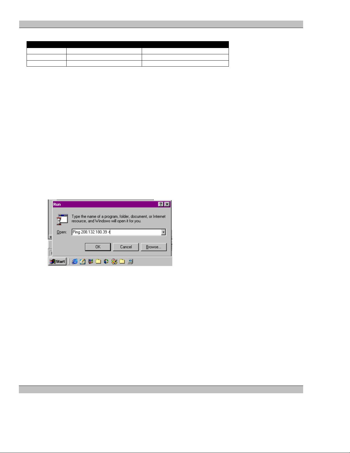
MS9400 HD FrEND User Guide Appendix D: Specifications
The most common IP Address classes are:
Class Name Valid Address Range Identifier Arrangement
Class A 0.0.0.1 to 127.255.255.254 NNN.HHH.HHH.HHH
Class B 128.0.0.1 to 191.255.255.254 NNN.NNN.HHH.HHH
Class C 192.0.0.1 to 223.255.255.254 NNN.NNN.NNN.HHH
Where:
NNN = Network identifier
HHH = Host identifier
Pinging a Device
You can perform a simple test from your control computer to check that the MS9400 is responding correctly. To
perform the test, you will use a command called “PING” (Packet Internet Groper).
Performing a Ping
1. Click on the Windows Start button, and from the menu choose Run.
2. In the Run dialog box, type in the following:
ping xxx.xxx.xxx.xxx -t
Where 'xxx.xxx.xxx.xxx' is the IP Address of the MS9400 that you wish to test.
3. A 'DOS Window' will then open and show a series of responses as in the examples below.
4. To stop the ping command, press Ctrl + C on the keyboard.
Example 1: A successful Ping
If you have successfully 'pinged' the address 208.132.180.39, you will get the following response:
Reply from 208.132.180.39: bytes=32 time=2ms TTL=32
This response indicates that the device at the specified address is communicating correctly.
NOTE: The response 'time' value may vary according to network traffic.
Example 2: Unsuccessful Pings
If you are not successful pinging the address, you will get one of two messages. The message returned will
indicate the type of problem.
52 Rev. 1.54
Page 53

MS9400 HD FrEND User Guide Appendix D: Specifications
A message of:
• Request timed out - indicates that there has been no response from the specified address. Either the device
is not receiving data from the computer or the device is sending data. Check the data cabling, power and
setup of the affected device.
• Reply from 208.132.180.48: Destination host unreachable- indicates that you are trying to ping an
address with a different network identifier than your computer. Check the value of the PC’s IP address
and compare it to that of the device – the network identifiers (the first three sets of numbers in the IP
addresses) are mismatched.
53 Rev. 1.54
Page 54

MS9400 HD FrEND User Guide Appendix D: Specifications
Appendix B: An Introduction to MPEG
It is not an exaggeration to say there is a revolution in the world of television broadcasting, often referred to as the
digital revolution. The ability of computers and related technology to process digital video, is leading to new
possibilities of interactivity. MPEG is one of the key technologies driving this revolution.
In an analog communication system, a transmitter sends voltage variations, which a receiver uses to control
transducers such as loud speakers, or TV cathode ray tubes. In a digital system the transmitter encodes the analog
voltage into a sequence of zeros and ones (called bits); this bit stream is transmitted to a receiver. The receiver
reconverts or “decodes” the bit stream back into the original analog voltage variations.
Primary advantages of digital representation of information are ease of manipulation and robustness of the data
stream. Digital data can be copied an infinite number of times and the quality will not degrade. Digital data can be
easily manipulated with a computer and distributed through a large number of different mediums.
Digital and Compression Video
Having determined that storing analog signals in a digital form is a good thing, what does this mean for television?
In the early days of digital video processing it was determined that the resolution for a digital representation of an
NTSC frame (single picture), needs to be 720 pixels across by 480 lines to produce an acceptable quality image.
At this resolution about 20 Mega bytes of data is required to represent a second of NTSC standard video.
To represent a High Definition signal over 5 times this quantity of data is required. Even with today’s computing
technology, these are huge numbers to work with. A method is needed to reduce the amount of data that is used to
represent the video stream. This is called Compression. Compression falls into two basic types, Loss-less and
Lossy. As the name implies, loss-less compression is able to recreate the original digital data exactly. Lossy
compression uses information in the input stream, which can be discarded without noticeable degradation of the
stream.
What is MPEG?
MPEG (Moving Picture Experts Group) was started in 1988 as a working group within ISO/IEC with the aim of
defining standards for digital compression of audio-visual signals. MPEG's first project, MPEG-1, was published
in 1993 as ISO/IEC 11172 [1]. It is a three-part standard, defining audio and video compression coding methods,
and a multiplexing system, for interleaving audio and video data so that they can be played back together. MPEG1 principally supports video coding up to about 1.5 Mbit/s giving quality similar to VHS and stereo audio at 192
bit/s. It is used in the CD-i and Video-CD systems for storing video and audio on CD-ROM.
During 1990, MPEG recognized the need for a second, related standard for coding video for broadcast formats at
higher data rates. The MPEG-2 standard [2] is capable of coding standard-definition television at bit rates from
about 3-15 Mbit/s and high-definition television at 15-80 Mbit/s. MPEG-2 extends the stereo audio capabilities of
MPEG-1 to multi-channel surround sound coding. MPEG-2 decoders will also decode MPEG-1 bit streams.
Drafts of the audio, video and systems specifications were completed in November 1993 and the ISO/IEC
approval process was completed in November 1994. The final text was published in 1995.
MPEG-2 aims to be a generic video coding system supporting a diverse range of applications. Different
algorithmic 'tools', developed for many applications, have been integrated into the full standard. To implement all
the features of the standard in all decoders is unnecessarily complex and a waste of bandwidth, so a small number
of subsets of the full standard, known as profiles and levels, have been defined:
54 Rev. 1.54
Page 55

MS9400 HD FrEND User Guide Appendix D: Specifications
• A profile is a subset of algorithmic tools
• A level identifies a set of constraints on parameter values (such as picture size and bit rate).
A Decoder that supports a particular profile and level is only required to support the corresponding subset of the
full standard and parameter constraints.
The MPEG compression standard is now in use throughout the television broadcast community.
A full description of the specific compression techniques employed by MPEG is beyond the scope of this
introduction. The rest of this section introduces and explains some of the terms commonly used in relation to
MPEG video.
I, B and P frames.
In order to achieve significant compression, MPEG implements an “encode only changes” mechanism. For
example in a typical video sequence, much of the image stays the same from frame to frame (except during a cut
of course). In that case why bother storing the static information with every frame?
MPEG uses this feature of video to only encode the changes from frame to frame. A problem with using this
technique is that random access becomes very difficult, because displaying a frame requires knowledge of all the
previous frames that the required frame has changed from. To overcome this problem, MPEG periodically
encodes a complete frame. With this in mind the following definitions describe the different frame types that may
be found in an MPEG stream.
I frames. These are frames that contain a complete Image. I frames act as the random access points into the video
stream.
P Frames. These frames contain only the differences from the previous frame.
B Frames. These frames contain the differences between the previous frame and the next frame. This may seem
like a strange concept. How can a video frame use information from a frame in the future? The answer is that an
MPEG encoder re-orders the frames in the stream, so that the decoder has all the necessary data to generate the B
image.
Of these frame types, B frames give the best compression, typically six times more than I frames.
Groups Of Pictures - GOP
As discussed above MPEG Video frames are encoded as three different picture types, I, B and P. Of these, I
frames are complete images and can be used as random access points into the video stream. Encoders will usually
insert an I frame into the stream at fixed intervals, every 15 frames for example. The arrangement of B and P
frames following each I frame usually follows a fixed pattern. These repeating patterns are referred to as groups of
pictures (GOP). A GOP always begins with an I frame, and can contain an embedded timecode.
A GOP can be either closed or open. In a closed GOP the B-pictures following an I frame have been generated
using only backwards prediction (i.e. using previous frames). This means that the B frames can be decoded
following a random access. Closed GOPs are generally preferred over Open GOPs for this very reason.
55 Rev. 1.54
Page 56
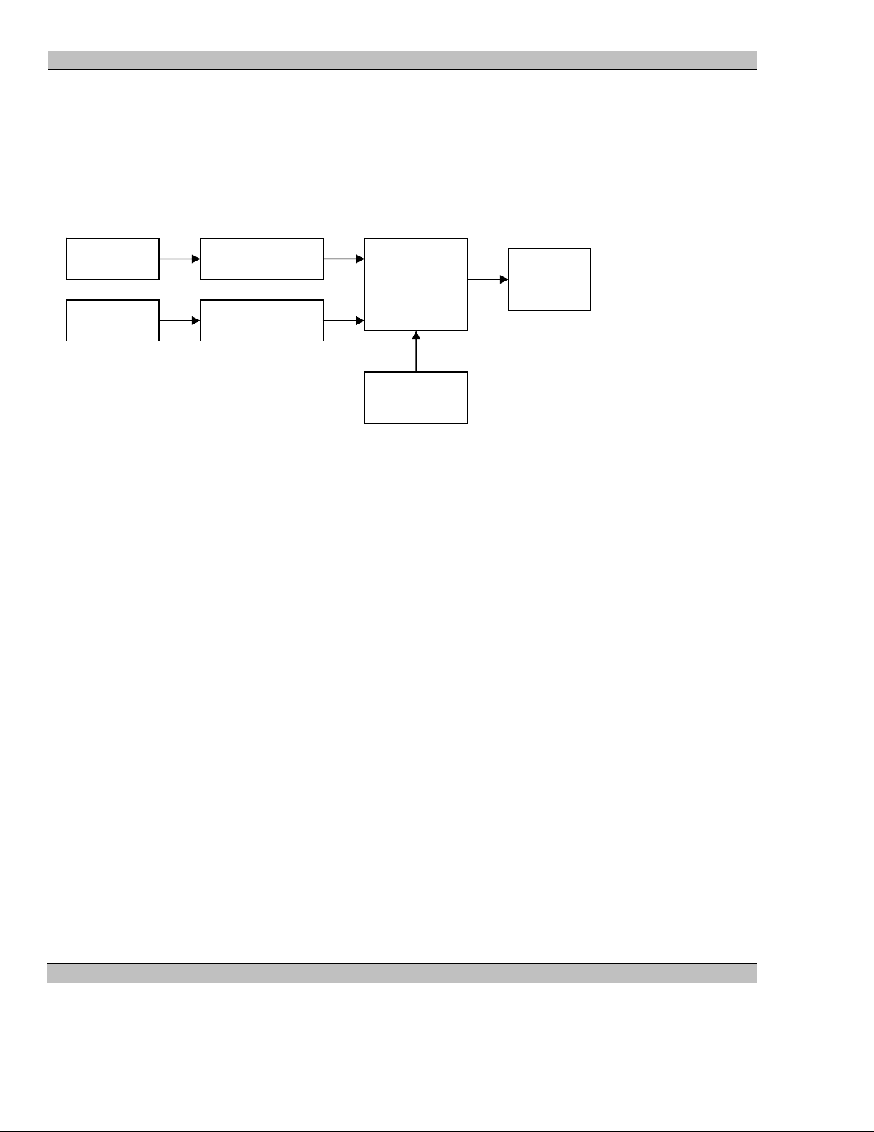
MS9400 HD FrEND User Guide Appendix D: Specifications
Multiplexes And Elementary Streams
So far the discussion has concentrated on audio and video as if they were completely separate entities. Most
applications using MPEG require audio and video to be combined, somehow, in such a way that during playback
they remain synchronized (i.e. Lip Sync). In the MPEG world the audio and video are referred to as Elementary
streams and the “magic” that combines audio, video and provides the synchronization is called a multiplex. The
following diagram shows a greatly simplified version of an MPEG encoder.
Audio Data
Video Data
Mpeg Encode
Mpeg Encode
Multiplexer
Output
Stream
As the audio and video data passes through the multiplexer, they are arranged into packets, each of which is
stamped with the current time from the system clock. These packets are named PES packets, for Packetized
Elementary Stream and the time stamps are referred to as PTSs (Presentation TimeStamps). The MPEG timing is
structured such that each elementary stream in a multiplexed stream is linked to the system clock (as opposed to
each other).
When the decoder plays back an MPEG stream, the video and audio data packets are “presented” at the times
specified by the PTSs in the PES packets.
It is important to understand that the PES times are features of Multiplexing audio and video into single streams.
They are not included in elementary streams. Playback of elementary streams relies on the implicit timing of the
stream. For example, an NTSC video stream needs to be presented at 29.97 frames per second. For audio streams,
the playback rate is the same as the sampling rate, for example 48KHz.
NOTE: This scheme sounds good in theory. Unfortunately, we have experienced that many encoders introduce
some errors into the PTS scheme. This may be a single bad time on a single packet, or even times completely out
of sync between Audio and Video.
The MPEG standard defines three different multiplex methods designed for different applications.
System
Clock
System Stream
A system stream is the MPEG 1 mechanism for combining an audio and a video elementary stream into the same
stream.
Program Stream
A program stream is one of two MPEG 2 mechanisms for combining an audio and a video elementary stream into
the same stream. In doing this, the program stream adds timing information for keeping the audio and video
synchronized. Program streams are designed for use in closed systems, where there is a very small chance of
errors occurring in the data stream.
56 Rev. 1.54
Page 57

MS9400 HD FrEND User Guide Appendix D: Specifications
Transport Stream
A transport stream is another MPEG 2 mechanism for combining audio and video elementary streams. It has the
following two differences from Program streams:
• The packet size is much smaller, therefore allowing easier recovery from bit errors in the stream.
• The transport stream can contain any number of different audio and video stream pairs.
Transport streams were designed for the Television broadcast industry where errors may be common in the data
streams transmitted from satellite, and there may be many different TV channels broadcast in the same stream.
NOTE: The MS9400 requires all MPEG files to be multiplexed as transport streams. Please refer to the encoding
guidelines for full details of mastering content.
57 Rev. 1.54
Page 58

MS9400 HD FrEND User Guide Appendix D: Specifications
Appendix C: Encoding Guidelines
The following notes present encoding details required for the MS9400 High Definition Video Player.
• MPEG files must be encoded as a Transport Stream.
• Elementary Video stream must be Main Profile High Level MP@HL
• Elementary Audio Stream must be AC3 encoded.
• Transport stream packet size is 188bytes. This is the standard size, although some encoders generate
packets of 204 bytes. The extra data contains error detection information, used for satellite transmission.
• Stream must start with an I frame and finish on a 188 bytes packet boundary.
• The two most popular resolutions supported are 1920 x 1080 x 59.94 interlace and 1280 x 720 x 59.94
progressive.
• Recommended Video PID numbers are 17, 33 & 49. Audio PID numbers are video PID + 3. Try to ensure
that all files are encoded with the same PID. MediaSonic normally use 49.
• The standard ATSC bit rate is 19.39Mb/s. Higher bit rates up to 30Mb/s can be accommodated.25Mb/s is
an excellent compromise between image quality and file size (storage).
• It is preferable to use closed Group of Pictures (GOPs) if this option is available with the encoder. The
preferred, though not required, GOP size is 15 frames. This provides a good compromise between
compression and random access in the stream.
• A GOP pattern containing I, B & P frames will provide the most efficient compression.
I B B P B B P… generally produces good results.
• Each GOP should contain a sequence header.
4:2:0.
58 Rev. 1.54
Page 59

MS9400 HD FrEND User Guide Appendix D: Specifications
Appendix D: Specifications
Primary Video Output
Format: RGBHV / YPrPb to SMPTE274M and 296M
Tri level sync on YPrPb mode as specified by EIA770
HD - Video Connector
15 pin miniature D type socket
Pin Number Name Pin Number Name
1 Red/Pr 9 No Connect
2 Green/Y 10 Sync Ground
3 Blue/Pb 11 No Connect
4 No Connect 12 No Connect
5 No Connect 13 H Sync
6 Red Ground 14 V Sync
7 Green Ground 15 No Connect
8 Blue Ground
Secondary Video Outputs:
Y/C
4-Pin DIN connector
COMPOSITE
BNC connector
59 Rev. 1.54
Page 60

MS9400 HD FrEND User Guide Appendix D: Specifications
Digital Video Decoder
ISO/IEC 13818-2 MPEG2 Compliant Video Decoder supports MP@HL decoding.
ISO/IEC 13818-1 Transport stream compliant
All ATSC compliant decode formats supported
Better than ATSC quality using data rates up to 35Mbps
1920 x 1080, 1280 x 720, 720 x 480
16:9, 4:3, Aspect Ratio support
Flexible Format Converter
High quality up / down converter of source video to selected display format.
Video Output Formats
SMPTE274M / SMPTE296M
Aspect Ratio 16:9, 4:3
1920 x 1080i
1280 x 720p
720 x 480p
Video Outputs Electrical
Analogue Output Color Space Support
SMPTE 170M
SMPTE 240M
ITU-R-BT-709
ITU-R-BT-470-2-SystemM
60 Rev. 1.54
Page 61

MS9400 HD FrEND User Guide Appendix D: Specifications
Audio
Stereo analog audio output via L/R RCA phono line out connector.
Stereo Audio 100mV p-p
Front panel Volume control
Audio Processing
Dolby Digital AC3
Sampling Rates 44.1KHz, 48KHz
Audio Bit Rate 384Kbps
SPDIF
Output via RCA phono connector
Digital Audio IEC – 61937 (SPDIF)
Audio Output Level 1V p – p
Audio Output Impedance 600 ohms
Network
RJ45 Ethernet 10/100Base T auto sensing.
Physical Features
Chassis Weight 13 lbs.
Chassis Dimensions 2.01" (H) x 11.36" (W) x 12.37" (D)
51.1mm (H) x 288.4mm (W) x 314.2mm (D)
Power, Voltage 110/220 VAC 50/60 Hz Auto Ranging, 250 Watts
Environmental 10 to 40C Ambient, 90% RH non-condensing
Safety Compliance UL, CSA,
61 Rev. 1.54
Page 62

MS9400 HD FrEND User Guide Index
Index
Command String 29
A
Audio Format 9
SPDIF/5.1 12
Stereo 12
Audio Off/On 20
Audio Volume Control 23
Day of Week 29
End Date 29
Events 29
Example 30
Start Date 29
F
C
CE Compliance 3
Communications
Ethernet 50
IP Address 51
Pinging 52
RS-232 50
Static Assignment 51
TCP/IP Addressing 50
Control Interface Module 45
5VDC 45
Blank Plate 45
Inputs 45
Outputs 45
D
Digital Inputs 45
Input Circuit Wiring 45
Digital Outputs
Relay Changeover contacts 46
FCC Compliance 4
Front Panel
IR WINDOW 11
POWER LED 11
RESET 11
STAND BY 11
STATUS LED 12
Function Macros 48
GPIO 49
GPIO Example Sequence 49
IR Remote 48
G
GPIO SeeControl Interface Module
GPIO Commands 47
H
High Definition 54
I
E
ESCAN 9, 21, 34, 36
Event Scheduler 28
Event Script 28
Event Script Format 28
Event Script Format
62 Rev. 1.54
IR Remote 16
Preset Button Functions 16
L
Loop Mode 20
Page 63

MS9400 HD FrEND User Guide Index
M
Test File 31
Playlist Mode 20
Menu 14, 18
Display 19
Product Serial No. 21
PTS 56
Playlists 20
Remote-RS232 22
Remote-TCP/IP 23
System 21
Q
Quick Start 14
MPEG 54
GOP 55
I, P & B Frames 55
R
MPEG-1 54
MPEG-2 54
Level 55
Profile 55
Multiplex 56
Program Stream 56
System Streams 56
Transport Stream 57, 58
MPEG data loading 24
MPEG Encoding Guidelines 58
AC3 Audio 58
Bit Rates 58
Common video resolutions 58
GOP 58
MP@HL 58
PID 58
Transport Stream Packet size 58
Multiplex 56
Rear Panel 12
AUDIO 12
ETHERNET 12
POWER OFF/ON 12
RS232 control 12
USB 12
VIDEO 12
Remote Control Protocols 35, 44
Configuration Commands 37
GPIO Commands 43
Media Management Commands 38
Parameter Types 35
Playback Commands 41
Playlist Commands 39
Status Commands 43
Text Command Structure 35
Reset
Display 16, 19
RJ45 Ethernet 44
N
RJ45 Pinout 44
NTSC 54
S
P
Serial Port Pinout 44
Set-Up 15
PES 56
PID Search 20
Software Version No. 21
System Diagram 13
playing Media Files
Startup playlist 34
Playing Media Files 31
T
Menu during playback 32
Playlists 32
Rename playlist 33
63 Rev. 1.54
TCP/IP 9
Default Gateway 23
Page 64

MS9400 HD FrEND User Guide Index
IP Address 23
Video Output Resoltion 19
Subnet 23
W
V
Wall Mounting 10
Video Format 9
64 Rev. 1.54
 Loading...