

Page 1
MS9200P
MPEG-2 HD Video Players
Control Application Software
User Guide
Streaming AV Products
Revision 6.8
08 2013
Page 2

HD Player Preface
Registered Trademarks
(®)
AVTrac, Cable Cubby, CrossPoint, eBUS, EDID Manager, EDID Minder, Extron, Flat Field, GlobalViewer, Hideaway, Inline, IP Intercom, IP Link, Key
Registered Service M ark
(SM)
:
S3 Service Support Solutions
Trademarks (™)
AAP, AFL (Accu-Rate Frame Lock), ADSP (Advanced Digital Sync Processing), AIS (Advanced Instruction Set), Auto-Image, CDRS (Class D Ripple
Copyright
© 2013 Extron Electronics. All rights reserved.
Trademarks
All trademarks mentioned in this guide are the properties of their respective owners.
The following registered trademarks
®
, registered service marks
(SM)
, and trade marks
(TM)
are the property of RGB Systems,
Inc. or Extron Electronics:
Minder, LockIt, MediaLink, PlenumVault, PoleVault, PowerCage, PURE3, Quantum, SoundField, SpeedMount, SpeedSwitch, System Integrator,
TeamWork, TouchLink, V-Lock, VersaTools, VN-Matrix, VoiceLift, WallVault, WindoWall, XTP and XTP Systems
Suppression), DDSP (Digital Display Sync Processing), DMI (Dynamic Motion Interpolation), Driver Configurator, DSP Configurator, DSVP (Digital
Sync Validation Processing), FastBite, FOXBOX, IP Intercom HelpDesk, MAAP, MicroDigital, ProDSP, QS-FPC (QuickSwitch Front P anel Controller),
Scope-Trigger, SIS, Simple Instruction Set, Skew-Free, SpeedNav, Triple-Action Switching, XTRA, ZipCaddy, ZipClip
2 Rev. 6.8
Page 3

HD Player Preface
Preface
About This User Guide
This manual contains detailed information about your Electrosonic HD Player unit. The main components are
• Descriptions of the various HD Players (MS9100P, MS9100D, MS9200P)
• System connection information
• Using the Electrosonic MS9000 HD Player Control Application Software
• Using the Windows™ Media Player
We recommend that the user read Chapter1: Introduction/Quick Reference Guide (pages 9-21) before setting up
the HD Player. This will give a basic understanding of how to use the HD Player.
We assume that the user has a working knowledge of common menus and commands necessary for operation of a
personal computer.
The manual is comprised of the following chapters:
Chapter 1: Introduction/ Quick Reference Guide
Chapter 2: The Playlist Display
Chapter 3: The Transport & Status Display
Chapter 4: The Log File/Information Windows
Chapter 5: HD Player Configuration
Chapter 6: Timecode
Chapter 7: Soft Edging /Display Overlap
Chapter 8: Genlock
Chapter 9: Brightness-Contrast-Saturation
Chapter 10: Configuration Files
Chapter 11: Remote Control Configuration
Chapter 12: Remote Control Protocols
Chapter 13: Video Output Formats
Chapter 14: Application Notes
Appendix A: TCP/IP Communications
Appendix B: An Introduction to MPEG
Appendix C: Encoding Guidelines
Appendix D: Specifications
Glossary
A full contents list appears after this preface.
3 Rev. 6.8
Page 4

HD Player Preface
VERSION
DATE
BY
COMMENTS
6.0
10.15.02
SS/AG
PRELIMINARY Release
6.1
10.16.03
SS
Add 2nd. Encoder card; general updates
6.2
03.23.04
SS
Add 9100D Power information
6.3
06.25.04
SS
Update Command Reference
6.4
04.18.05
SS
Update Command Reference
6.5
10.05.05
SS
Update Command Reference
6.6
9.29.08
IGS
Updated ES-Gen daisy chain limit = 3
6.7
2.22.10
IGS
Electrosonic Inc. update.
6.8
7.31.13
DRO
Note that “Confidence Display” is No Longer Supported
Document History
This manual applies to HD Player Software Release 7.02
Additional Trademarks
MEDIASONIC ®, MS ® and the MEDIASONIC ® logo are registered trademarks of ELECTROSONIC Ltd.
ELECTROSONIC
WINDOWS
All other brand and product names are trademarks or registered trademarks of their respective holders.
®, ES ® and the ELECTROSONIC ® logo are registered trademarks of ELECTROSONIC Ltd.
® is a registered trademark of MICROSOFT CORPORATION.
4 Rev. 6.8
Page 5

HD Player Table of Contents
Table of Contents
Preface ................................................................................................... 3
About This User Guide ....................................................................................................................................... 3
Document History .............................................................................................................................................. 4
Trademarks ......................................................................................................................................................... 4
Table of Contents .................................................................................. 5
Chapter 1: Introduction/Quick Reference Guide ........................ 11
Main Features ................................................................................................................................................... 11
HD Player Connections – Interface .............................................................................................................. 11
Common Connections .............................................................................................................................. 11
Mouse ............................................................................................................................................................ 11
Keyboard ...................................................................................................................................................... 12
Computer Monitor ...................................................................................................................................... 12
LAN ................................................................................................................................................................. 12
Remote Control (C OM M Port) .................................................................................................................. 12
Timecode In/Out ......................................................................................................................................... 12
Genlock In/out, Composite Black Burst .................................................................................................. 12
SPDIF .............................................................................................................................................................. 12
The MS9200P ................................................................................................................................................. 13
The MS9100P ................................................................................................................................................. 15
The MS9100D ................................................................................................................................................ 16
Getting Started ................................................................................................................................................ 18
MS9200P, MS9100P (Rack mounted players) ......................................................................................... 18
MS9100D (Desktop player) ........................................................................................................................ 18
The Windows™ Media Player ........................................................................................................................ 18
To start the Media Player ........................................................................................................................... 18
To play a different clip ............................................................................................................................... 19
The Electrosonic MS9000 HD Player Control Application software ........................................................ 20
To Start the Ele c tr osonic HD Player: ......................................................................................................... 20
The Electrosonic HD Player Interface .......................................................................................................... 20
To Load a Clip .............................................................................................................................................. 21
To Play a Clip ............................................................................................................................................... 22
The Electrosonic HD Player, Main Menu ..................................................................................................... 22
The File Menu ............................................................................................................................................... 22
The View Menu ............................................................................................................................................ 22
The Configurations Menu .......................................................................................................................... 23
The Help menu ............................................................................................................................................. 23
MS9100D Users, additional Windows™ Media Player information ......................................................... 25
Output Format ............................................................................................................................................. 25
Output Mode ............................................................................................................................................... 26
Audio Mode ................................................................................................................................................. 26
Genlock Mode ............................................................................................................................................ 26
Update .......................................................................................................................................................... 27
Chapter 2: The Playlist Display ................................................... 28
The Playlist ......................................................................................................................................................... 28
Adding a clip to the Playlist ........................................................................................................................... 28
5 Rev. 6.8
Page 6

HD Player Table of Contents
The Clip Properties Dialog .............................................................................................................................. 29
Clip name ...................................................................................................................................................... 30
Timecode ...................................................................................................................................................... 30
Selecting and Playing a Clip.......................................................................................................................... 31
To Play a Clip ................................................................................................................................................ 31
Selecting and Playing a List (Sequence) ..................................................................................................... 31
Chapter 3: Transport & Status displays .......................................... 32
Transport status ................................................................................................................................................. 32
Stopped ......................................................................................................................................................... 32
Paused ........................................................................................................................................................... 33
Cueing ........................................................................................................................................................... 33
Playing ........................................................................................................................................................... 33
Frame Counter ................................................................................................................................................. 33
Current Timecode ............................................................................................................................................ 33
Mode Indicators ............................................................................................................................................... 33
Loop ............................................................................................................................................................... 34
Vid ................................................................................................................................................................... 34
Aud ................................................................................................................................................................. 34
Current Chapter and Clip Name .................................................................................................................. 34
Transport/Output Controls .............................................................................................................................. 34
Play ................................................................................................................................................................. 34
Cue ................................................................................................................................................................. 34
Pause .............................................................................................................................................................. 34
Auto-repeat (Loop) ..................................................................................................................................... 34
Audio Output ................................................................................................................................................ 34
Video Output: Black .................................................................................................................................... 35
Video Output ................................................................................................................................................ 35
Color Bars ...................................................................................................................................................... 35
Fast Forward/Loop Slider ................................................................................................................................ 35
Confidence Display ......................................................................................................................................... 35
Chapter 4: The Log / File Information Windows ............................ 36
The Log Window........................................................................................................................................... 36
The File Information Window ..................................................................................................................... 37
The Status Bar................................................................................................................................................ 38
Chapter 5: HD Player Configuration ............................................... 39
To Modify the Player Configuration .............................................................................................................. 39
The Channel Properties dialog ...................................................................................................................... 39
Set the channel to loop at startup ........................................................................................................... 40
Set the channel to start playing at startup ............................................................................................. 40
Video on at startup ..................................................................................................................................... 40
Audio on at startup ..................................................................................................................................... 40
Output black when file completes .......................................................................................................... 40
Enable AV Sync ............................................................................................................................................ 41
Base Channel Number ............................................................................................................................... 41
Audio Output Format .................................................................................................................................. 41
Output Standard .......................................................................................................................................... 41
Genlock ......................................................................................................................................................... 42
Advanced ......................................................................................................................................................... 42
To turn off the Video Confidence Display .............................................................................................. 42
6 Rev. 6.8
Page 7

HD Player Table of Contents
BCS – Brightness-Contrast--Saturation ..................................................................................................... 43
Overlap (Soft Edging or Edge Blending) ................................................................................................ 43
Output Format ............................................................................................................................................. 43
Chapter 6: Timecode ..................................................................... 45
Configuring as a Timecode Master ............................................................................................................. 45
The Timecode configuration dialog ............................................................................................................ 45
Start Time ...................................................................................................................................................... 46
Play At ........................................................................................................................................................... 46
Stop At ........................................................................................................................................................... 47
Configuring as a Timecode Slave ................................................................................................................ 48
Play At ........................................................................................................................................................... 48
Loop Input to Output ................................................................................................................................. 48
Configuring as a Timecode Reader ............................................................................................................ 49
Timecode Cable .............................................................................................................................................. 49
Chapter 7: Soft Edging/Display Overlap ...................................... 50
Videowall .......................................................................................................................................................... 50
Single Projector ................................................................................................................................................ 50
Introducing Soft Edging .................................................................................................................................. 50
Configuring a Soft Edged System ................................................................................................................. 52
Vertical and Horizontal Borders ................................................................................................................ 54
Gamma ........................................................................................................................................................ 55
Black Correction .......................................................................................................................................... 57
Update .......................................................................................................................................................... 58
Chapter 8: Genlock ....................................................................... 59
Genlock Mode ................................................................................................................................................. 59
Genlock Standalone/Master .................................................................................................................... 60
Genlock ES-Gen .......................................................................................................................................... 60
Genlock Cable ............................................................................................................................................ 61
Genlock Composite Black Burst ............................................................................................................... 61
Chapter 9: Brightness-Contrast-Saturation .................................... 62
To change a BCS setting: ............................................................................................................................... 62
Brightness ...................................................................................................................................................... 62
Contrast ........................................................................................................................................................ 62
Saturation ..................................................................................................................................................... 63
Chapter 10: Configuration Files .................................................... 64
Saving the current configuration ................................................................................................................. 64
Loading a configuration file .......................................................................................................................... 65
Chapter 11: Remote Control Configuration ................................ 66
The Remote Control Methods dialog .......................................................................................................... 66
To create a new Method .......................................................................................................................... 66
To Edit Method settings .............................................................................................................................. 67
To Delete a Method ................................................................................................................................... 67
The Remote Control Wizard - Method Type dialog .................................................................................. 67
The Remote Control Wizard - Serial Control Parameters (RS232) page ................................................ 68
7 Rev. 6.8
Page 8

HD Player Table of Contents
Remote Control Wizard Protocol page ................................................................................................... 68
The Remote Control Methods wizard TCP/IP page ................................................................................... 70
Chapter 12: Remote Control Protocols ....................................... 71
Serial Port Pinout ............................................................................................................................................... 71
RJ45 Ethernet..................................................................................................................................................... 71
RJ45 Pinout .................................................................................................................................................... 71
Text Command Protocol (Telnet Protocol) ................................................................................................. 71
To Run Telnet ................................................................................................................................................. 72
Command Structure ................................................................................................................................... 72
Command Reference ..................................................................................................................................... 73
Configuration Commands ......................................................................................................................... 73
Media Management Commands ........................................................................................................... 75
Playlist Commands ...................................................................................................................................... 76
Playback Commands ................................................................................................................................. 79
System/Status Commands ......................................................................................................................... 81
Timecode Commands ................................................................................................................................ 81
Miscellaneous Commands – (Telnet Protocol) ...................................................................................... 82
Examples ............................................................................................................................................................ 84
ES 4000 ................................................................................................................................................................ 84
Available Player Commands ......................................................................................................................... 85
Chapter 13: Video Outputs ........................................................... 86
The PCI HD Decoder Card Interfaces .......................................................................................................... 86
Primary Output: MS9200P/MS9100P/MS9100D ....................................................................................... 86
Secondary Output: MS9200P..................................................................................................................... 86
HDSDI: MS9200P ............................................................................................................................................ 87
Chapter 14: Application Notes ..................................................... 89
Synchronized playback .................................................................................................................................. 89
Content Preparation ................................................................................................................................... 89
Genlock ......................................................................................................................................................... 89
Playing in Sync. with Timecode ................................................................................................................. 89
Cueing and Playing with Serial control ................................................................................................... 89
Example: A Two Player System (two-channels) ......................................................................................... 91
TCP/IP ............................................................................................................................................................. 92
RS232 .............................................................................................................................................................. 92
Appendix A: TCP/IP Communications .......................................... 95
An Introductory Note ....................................................................................................................................... 95
Ethernet Communication ............................................................................................................................... 95
RS-232 ............................................................................................................................................................. 95
Ethernet ......................................................................................................................................................... 95
TCP/IP Addressing ............................................................................................................................................ 95
Dynamic Assignment .................................................................................................................................. 95
Static Assignment ........................................................................................................................................ 96
The IP Address ................................................................................................................................................... 96
Network and Host Identifiers ...................................................................................................................... 96
Class Names ................................................................................................................................................. 96
Choosing IP Addresses .................................................................................................................................... 97
Connecting to an Existing Network .......................................................................................................... 97
8 Rev. 6.8
Page 9

HD Player Table of Contents
Establishing an Independent Network .................................................................................................... 97
The Subnet Mask .............................................................................................................................................. 98
Accessing the PC’s Subnet Mask and IP Address ..................................................................................... 98
Opening the Network Dialog Box: ........................................................................................................... 98
Accessing the IP Address: ......................................................................................................................... 98
Assigning the HD Player IP Address and Subnet Mask ............................................................................. 99
Setting the Subnet Mask ............................................................................................................................ 99
Setting the IP Address ................................................................................................................................. 99
Saving the Subnet Mask and IP Address Values ................................................................................... 99
Pinging a Device ............................................................................................................................................. 99
Performing a Ping ........................................................................................................................................ 99
Example 1: A successful Ping .................................................................................................................. 100
Example 2: Unsuccessful Pings................................................................................................................ 100
Appendix B: An Introduction to MPEG ....................................... 101
Digital and Compression Video ............................................................................................................. 101
What is MPEG? ........................................................................................................................................... 101
I, B and P frames. ....................................................................................................................................... 102
Groups Of Pictures - GOP ........................................................................................................................ 102
Multiplexes And Elementary Streams .................................................................................................... 103
System Stream ........................................................................................................................................... 103
Program Stream ........................................................................................................................................ 103
Transport Stream ....................................................................................................................................... 104
Appendix C: Encoding Guidelines ............................................. 105
Appendix D: Specifications ........................................................ 106
Primary Video Output ................................................................................................................................... 106
Video Connector ...................................................................................................................................... 106
Secondary Video Output ............................................................................................................................ 106
HDSDI – Digital Video .................................................................................................................................... 107
Genlock ........................................................................................................................................................... 107
Graphics Output ............................................................................................................................................ 107
Network ........................................................................................................................................................... 107
Digital Video Decoder ............................................................................................................................. 107
Flexible Format Converter ....................................................................................................................... 108
Video Output Formats .............................................................................................................................. 108
Audio ................................................................................................................................................................ 108
Audio Processing ........................................................................................................................................... 108
SPDIF ................................................................................................................................................................. 108
System Control Aids .................................................................................................................................. 109
Glossary ............................................................................................. 110
Index .................................................................................................. 121
9 Rev. 6.8
Page 10

Page 11

HD Player Chapter 1: Introduction/Quick Reference Guide
Chapter 1: Introduction/Quick Reference Gui d e
The Electrosonic HD Player is a compact single channel High Definition (HDTV) playback device. It is designed
to playback MPEG files compressed to the SMTPE 296/274 specification as defined by the ATSC (Advanced
Television Standards Committee). The HD Player manipulates all program material in the digital environment to
ensure that image quality is maintained irrespective of the number of times a file is displayed or copied. Using the
computer/network topology, files may be transferred to and displayed on remote Players from a central
distribution location.
The HD Player product line consists of three versions to accommodate any HD playback application:
1. MS9200P Digital, Rack Mount model
2. MS9100P Analog, Rack Mount model (No longer available)
3. MS9100D Analog, Desktop model (No longer available)
Main Features
• Rack Mount versions are housed in rugged, industrial 19” rack mountable 3U cases, ensuri ng maxi m um
reliability, long product life and easy integration into Audio Visual installations. The desktop version is
designed for use in less rigorous environments
• Windows™ Media Player software for basic playback control
• Support for a wide range of remote control options, using serial RS232 or Ethernet TCP/IP interfaces.
• Networking capabilities provide the means to remotely upload new audio/video files to the Player.
• Standard “on-board” storage capacity (hard disk) of 40Gbytes. This provides a default maximum of 90
minutes of ATSC encoded HD material. Almost unlimited storage capacity can be achieved by adding
external storage in the form of disk raid arrays.
• A Status Bar at the bottom of the main display shows tips about commands available within each main
screen menu as the user moves the pointer along the list
HD Player Connections – Interface
All system connections are made at the back of the HD Player. The video outputs of your HD player appear at
connectors on PCI cards factory installed in the HD Player. Refer to Chapter 13 (Video Output Formats) for more
details on the output options of your HD Player – the interface will depend on which version of the HD Player you
are using and whether you intend to utilize the Soft Edging capability of the HD Player.
Common Connections
The following are common to all the Electrosonic HD Player versions. They are used as required by your
particular system.
Mouse
Connect the system mouse here
11 Rev. 6.8
Page 12

HD Player Chapter 1: Introduction/Quick Reference Guide
Keyboard
Connect the system keyboard here
Computer Monitor
Connect the HD Player monitor here.
LAN
Use this connection to copy data from a network on to the HD Player hard disk
Remote Con trol (CO M M Port)
See Chapters: 11 and 12
Timecode In/ Out
See Chapter: 6 (MS9100D must use optional MS9000 HD Player Software)
Genlock In/out, Compo site Black Burst
See Chapter: 8 (MS9100D must use optional MS9000 HD Player Software for Composite Video Black &
Burst synchronization)
SPDIF
Connect to your surround sound system (5.1) audio decoder.
The following figures illustrate the rear panel connections to the Electrosonic HD Players:
12 Rev. 6.8
Page 13
HD Player Chapter 1: Introduction/Quick Reference Guide
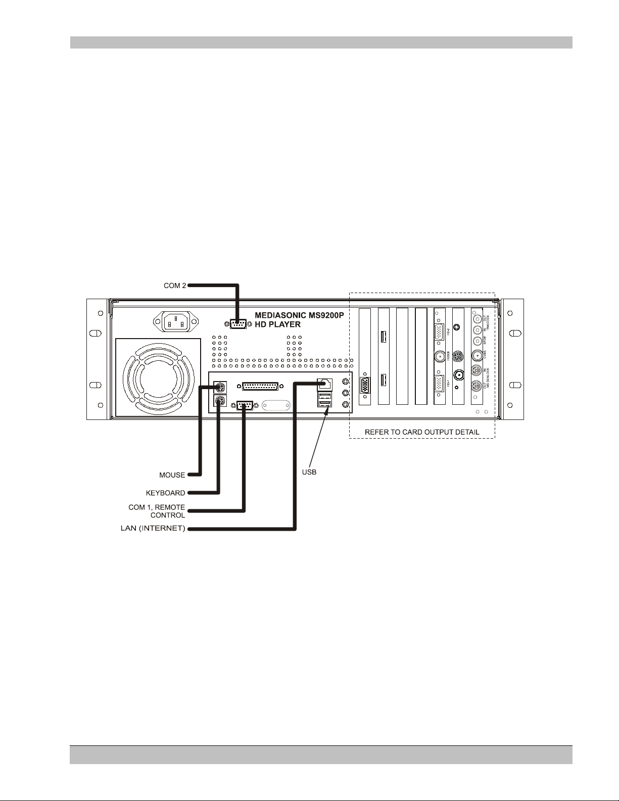
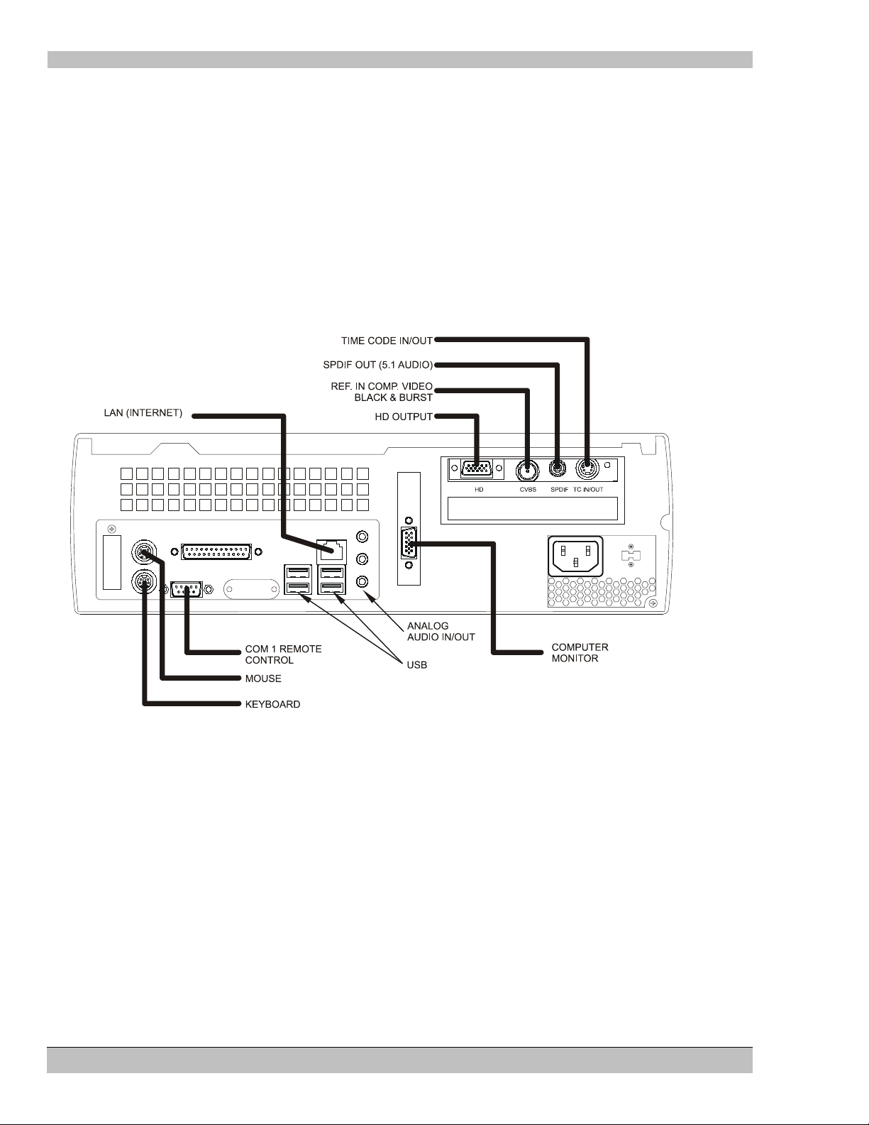
The MS9200P
Selected MS9200P features:
• Digital and Analog HD video outputs
• SPDIF 5.1 audio output
• Playback using the Electrosonic MS9000 HD Player Control Application software
• Windows™ MediaPlayer support included
• Support for Soft Edging of images
• Rack mounted enclosure
• ES-Gen Genlock and/or Composite Video Black & Burst synchronization
Figure 1. MS9200P, Digital HD Player, Rack Mount model connections
13 Rev. 6.8
Page 14
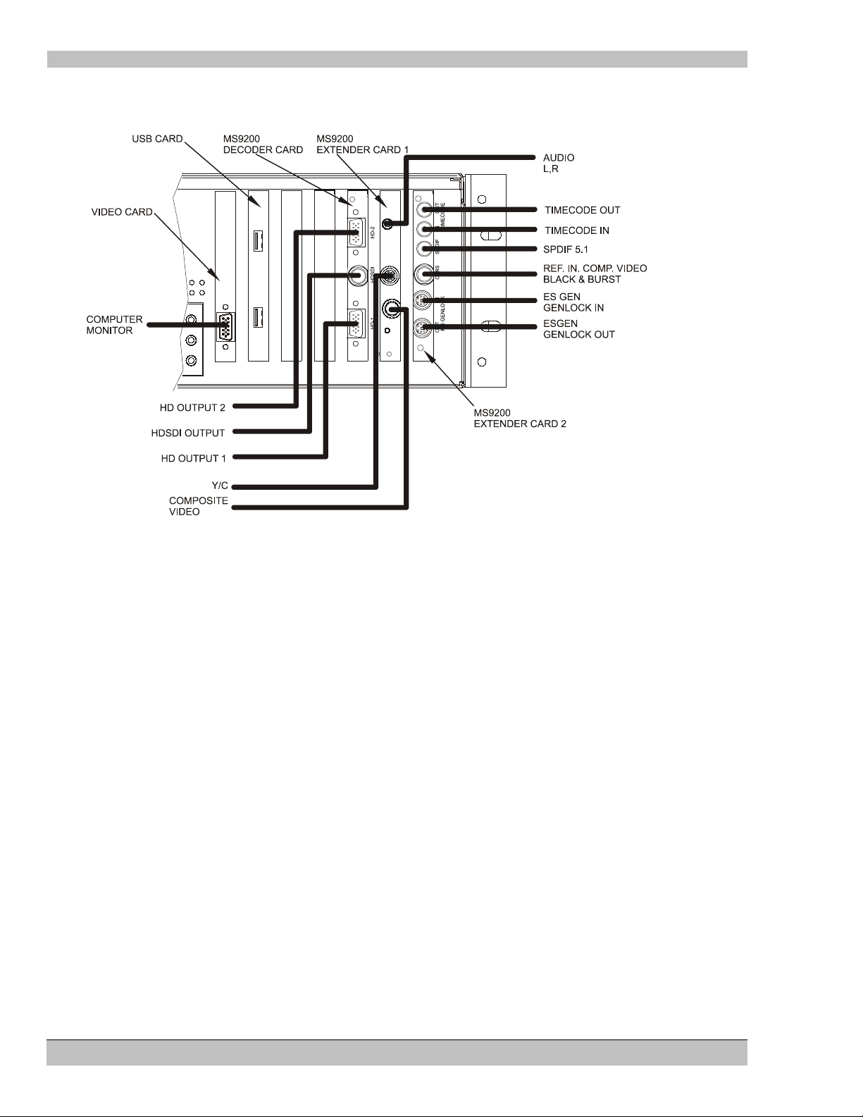
HD Player Chapter 1: Introduction/Quick Reference Guide
Figure 2 MS9200P, Digital HD Player Card Output Detail
14 Rev. 6.8
Page 15
HD Player Chapter 1: Introduction/Quick Reference Guide
DECODER CARD,
ANALOG (MS9100)
ANALOG
AUDIO OUT
TO HD DISPLAY
SPDIF OUT
(5.1 AUDIO)
REF . IN COMP. VIDEO
BLACK & BURST
TIME CODE
IN/OUT
USB NO CONNECTION
LAN (INTERNET)
KEYBOARD
MOUSE
RESET
MEDIASONIC MS9100P
HD PLAYER
COMPUTER
MONITOR
COM 1, REMOTE
CONTROL
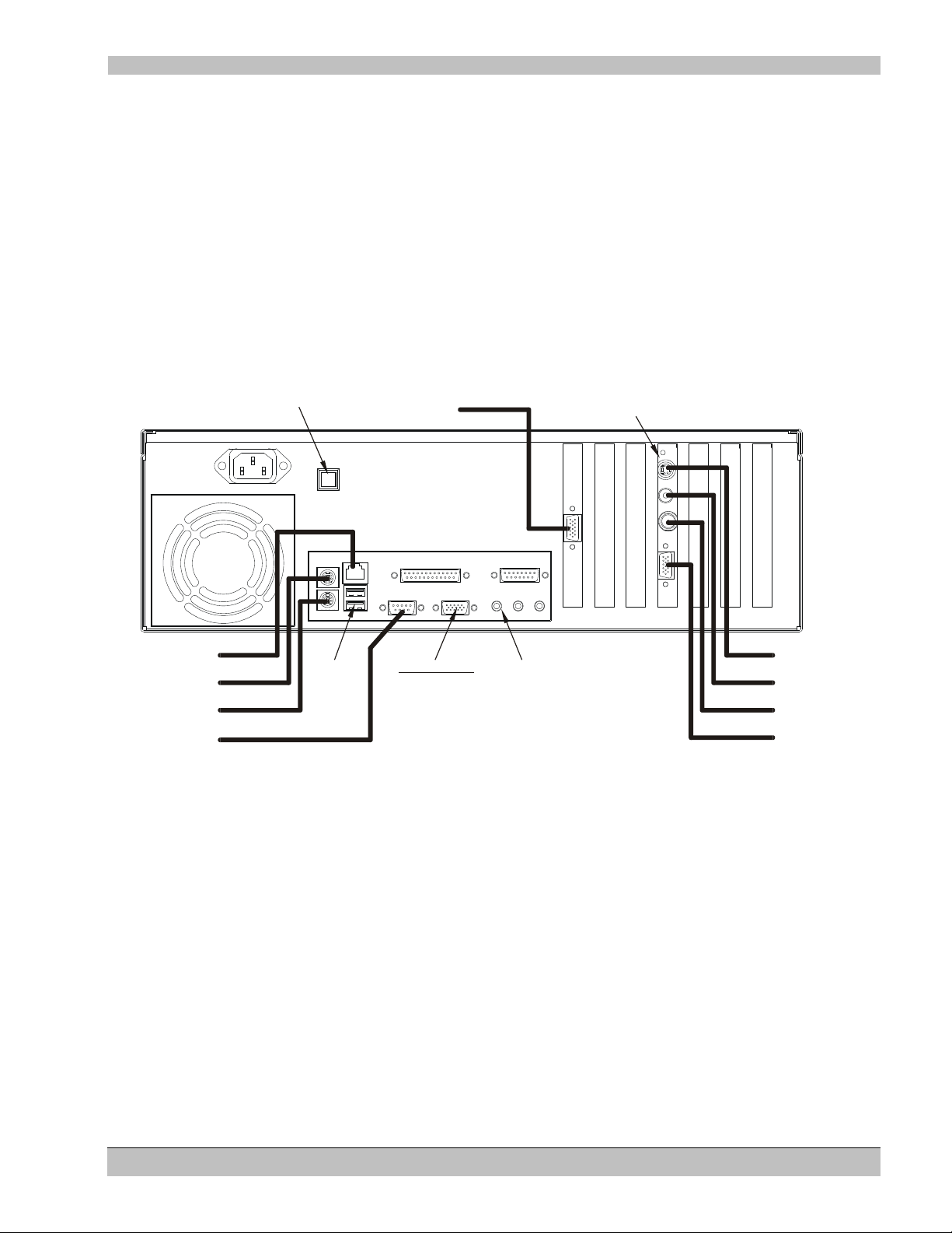
The MS9100P
Selected MS9100P features:
• Analog HD video outputs
• SPDIF 5.1 audio output
• Playback using the Electrosonic MS9000 HD Player Control Application software
• Windows™ MediaPlayer support included
• Rack mounted enclosure
• Composite Video Black & Burst synchronization
Figure 3. MS9100P, Analog HD Player, Rack Mount model connections
15 Rev. 6.8
Page 16
HD Player Chapter 1: Introduction/Quick Reference Guide
The MS9100D
Selected MS9100D features:
• Analog HD video outputs
• SPDIF 5.1 audio output
• Playback using Windows™ MediaPlayer
• Desktop installation
• Composite Black & Burst synchronization
• Optional Electrosonic MS9000 HD Player Control Application software
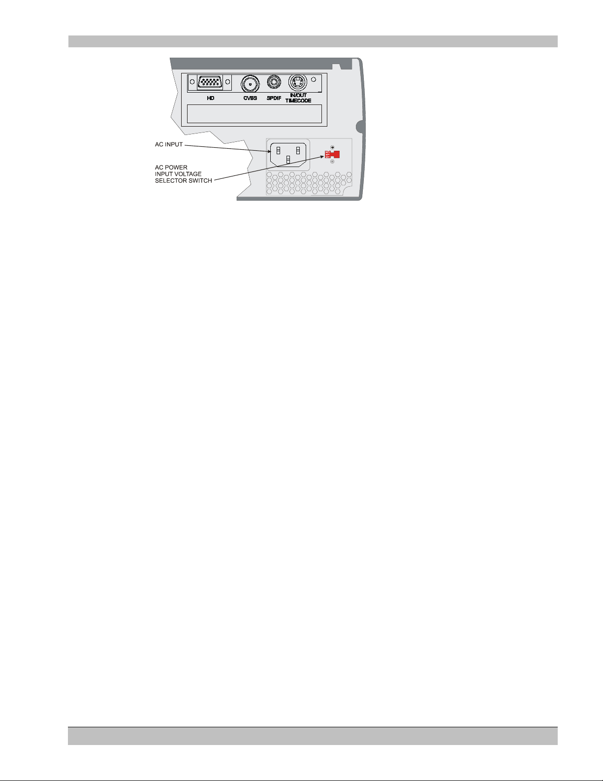
Figure 4. MS9100D, Analog HD Player, Desktop model connections
WARNING: Ensure that the AC Input Power Supply Switch located on the back of the 9100D HD Player is set to
the same voltage as the local supply.
An incorrectly set switch may result in damage to the unit upon power-up.
• Locate the red AC Power Input Voltage Selector Switch (refer to the following illustration).
• By means of a small screwdriver adjust the switch left/right until either 115 or 230 shows in the opening.
16 Rev. 6.8
Page 17
HD Player Chapter 1: Introduction/Quick Reference Guide
Figure 5. MS9100D, Analog HD Player, AC Power Input Voltage Selector Switch location
Although every effort has been made at our factory to make sure that the switch is set correctly before shipping to
a particular geographic location, we recommend that the user verify the switch setting before first-time power-up.
17 Rev. 6.8
Page 18
HD Player Chapter 1: Introduction/Quick Reference Guide
No Longer Supported
Play button
Now Playing
Double
click
Getting Started
By this time you have completed your system connections and are ready to begin using the HD Player.
MS9200P, MS9100P (Rack mounted players)
Users of the MS9100P and MS9200P models have two methods for controlling MPEG playback:
• The Electrosonic HD Player Control Application software, and/or
• The Windows™ Media Player software
MS9100D (Desktop player)
Purchasers of the MS9100D model utilize the Windows™ Media Player only - the Electrosonic HD Player
Control Application software is available at an additional cost.
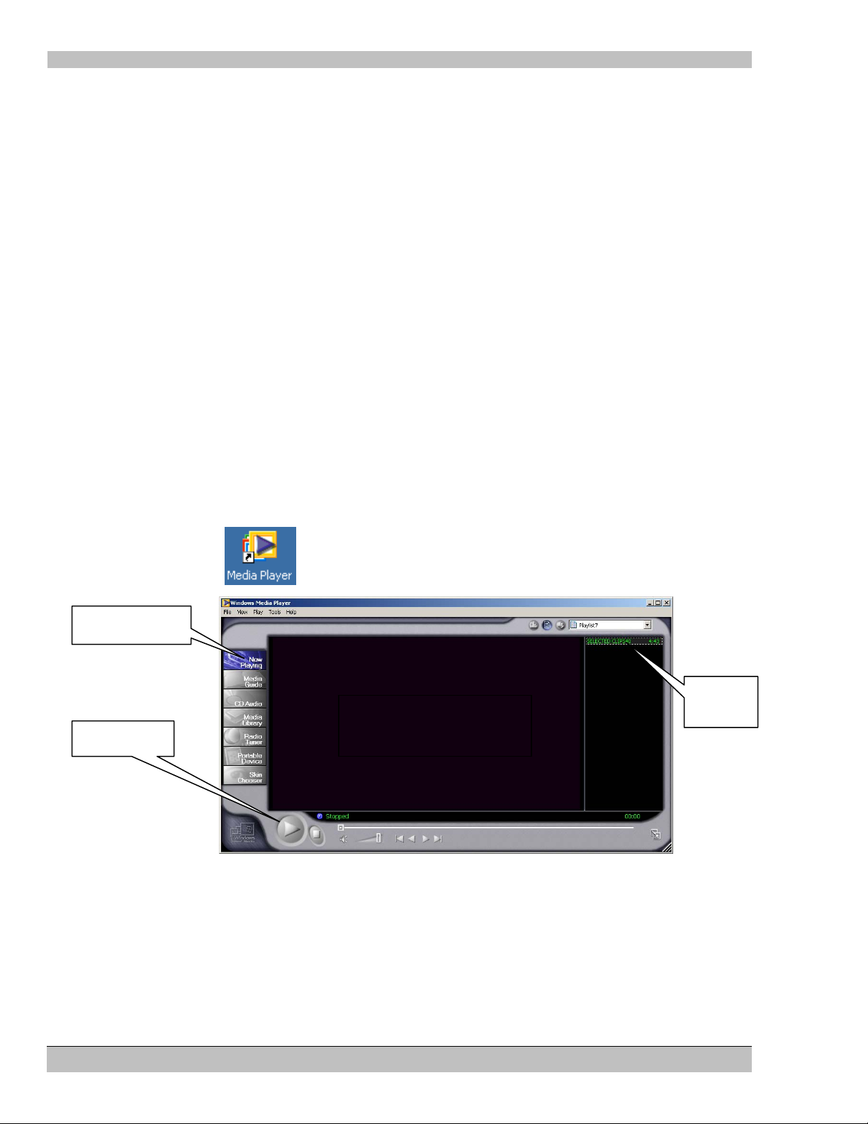
The Windows™ Media Player
The quickest way to verify your system set-up is to view a video clip with the included MediaPlayer software.
To start the Media Player
• Double-click the icon on your desktop. The interface shown below appears.
“Confidence Display”
• Click the Now Playing tab. The Media Player will list the last MPEG clip played in the top right hand
corner (Playlist area)
• Double-click the file in the list or click the Play button as indicated above
No Longer Supported: An image will appear in the Confidence Display that is a copy of the image being sent to
the video outputs of your HD Player.
18 Rev. 6.8
Page 19
HD Player Chapter 1: Introduction/Quick Reference Guide
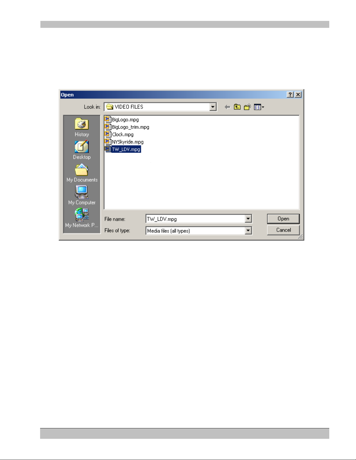
To play a different clip
• Click File on the main menu of the MediaPlayer;
• Click Open. The Player will open the VIDEO FILES folder if it has been used with MPEG files
previously. If not, you may have to browse to the VIDEO FILES folder and double-click the VIDEO
FILES folder in the Open window.
• Select the file you wish to play from the list in the window and click the Open button – the selected file
will begin playing.
Refer to the on-line MediaPlayer Help instructions for more information
19 Rev. 6.8
Page 20

HD Player Chapter 1: Introduction/Quick Reference Guide
The Electrosonic MS9000 HD Player Control Application software
The Electrosonic MS9000 HD Player Control Application software is an interface for more sophisticated HD
system Playback and Control.
Use the HD Player Control Application to:
• Set video output format
• Adjust video output quality settings
• Set Audio output format
• Assemble and organize Playlists
• Setup Soft Edged (Image Overlap) multi projector displays including adjustments for Gamma and Black
Correction
• Control other HD Players as well as itself in a Timecode Master/Slave system
• Remote control your system with commands from other devices
These and other features of the Electrosonic HD Player will be described in detail throughout this manual
To Start the Electrosonic HD Player:
• Double click the icon on your desktop or,
• Click the Windows™ Start button on your desktop, and select Programs/MediaSonic/HD Player.
The HD Player Control Application Graphic User Interface (GUI) appears.
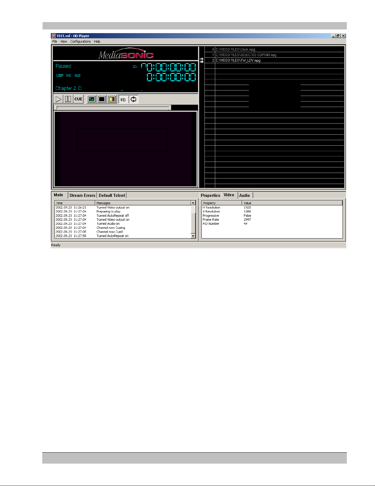
The Electrosonic HD Player Interface
The following is an image of the Electrosonic HD Player GUI:
20 Rev. 6.8
Page 21
HD Player Chapter 1: Introduction/Quick Reference Guide
No Longer Supported
“Confidence Display”
“Playlist
Display”
“Status/Transport
Controls Display”
“Log
“File Information
Window”
Window”
Display
The HD Player interface consists of several main “segments”:
• Status and Transport Controls Display
• The Playlist Display
• The Log Window
• The File Information Window
These “segments” will be discussed in greater detail in the relevant chapters.
To Load a Clip
1. Open a Windows™ Explorer window,
2. Select the MPEG file (clip) you wish to play
3. Drag the file onto the Playlist in the HD Player GUI. As the mouse is moved over the Playlist area, a
highlight bar will appear indicating where the files will be placed
21 Rev. 6.8
Page 22
HD Player Chapter 1: Introduction/Quick Reference Guide
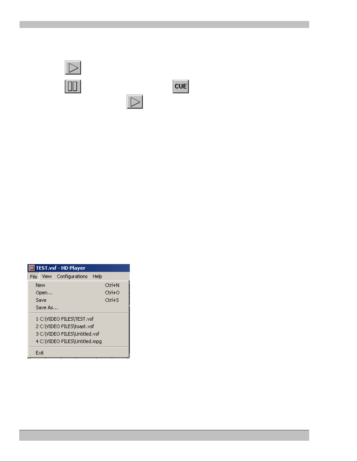
To Play a Clip
1. Double click the clip in the Playlist, this will Cue the start of the clip
2. Click
3. Click
take a few seconds), next click
(Play) button on the Transport to begin playing the clip.
(Pause/Stop) button to quit or click , the HD Player will re-cue the clip (this may
to restart the clip.
The Electrosonic HD Player, Main Menu
Use the Main Menu as in any Windows™ software. The Main Menu allows access to many basic functions of the
HD Player.
The File Menu
The HD Player utilizes the .vsf file format. These files hold all of the HD Player information or settings unique to
a particular clip; their file names appear in the File command menus.
Note: Refer to Chapter10 for more information
Use the File menu to:
• Open a New file for building a Playlist
• Open an existing .vsf file
• Save your file settings
• Save your settings as a new file
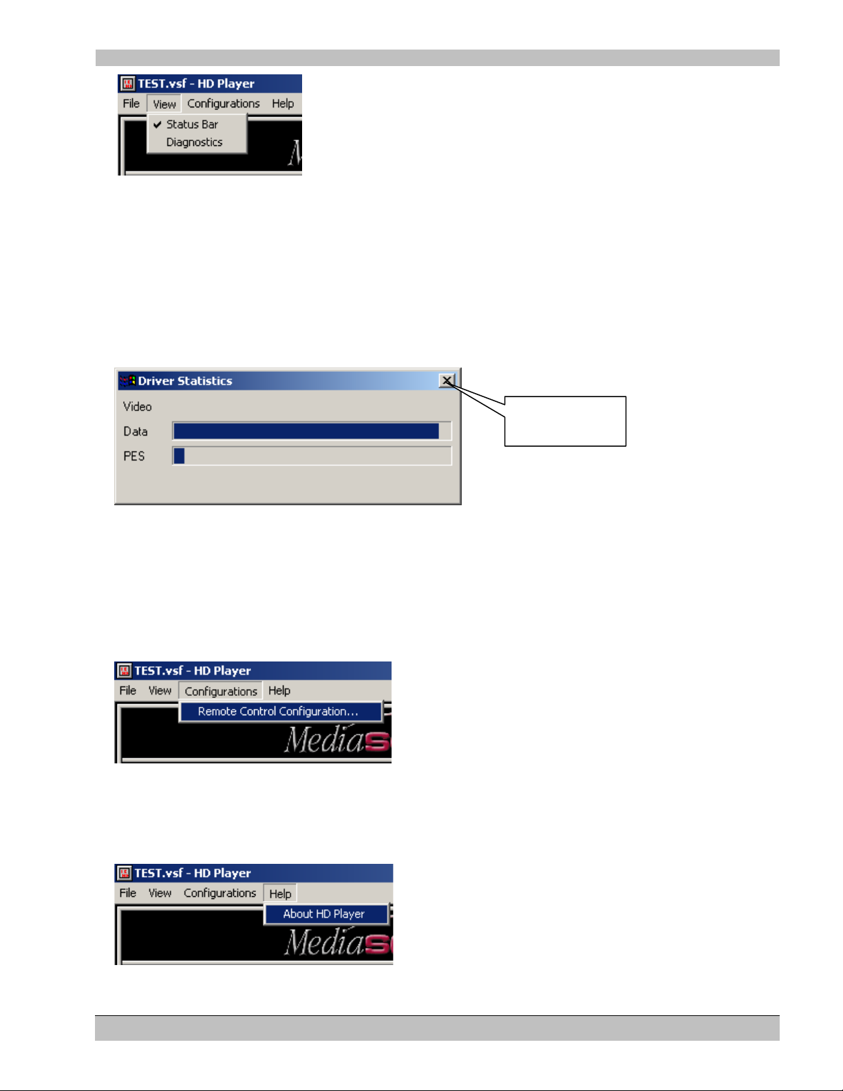
The View Menu
Open the View menu and select or de-select the item you wish to affect.
22 Rev. 6.8
Page 23
HD Player Chapter 1: Introduction/Quick Reference Guide
Click here to
close
The view menu allows the user to:
• Turn the Status display on or off
The Status Bar lists information about the main menu commands. Use the Status Bar to view quick tips about the
commands available on the main drop down menus. The display changes as you drag your pointer along the menu
options.
• Turn on the Driver Statistics window
The Driver Statistics window is used for information only.
The Configurations Menu
Select Configurations/Remote Control Configurations to open the Remote Control Wizard.
Note: Refer to Chapter11 for more information.
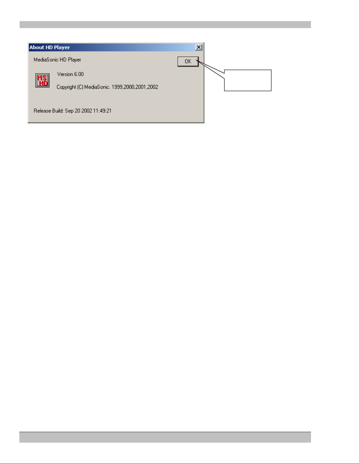
The Help menu
Select Help/About HD Player to verify the Version of HD Player software on your system.
23 Rev. 6.8
Page 24
HD Player Chapter 1: Introduction/Quick Reference Guide
Click here to
Close
The About HD Player display:
24 Rev. 6.8
Page 25
HD Player Chapter 2: The Playlist display
MS9100D Users, additional Windows™ Media Player information
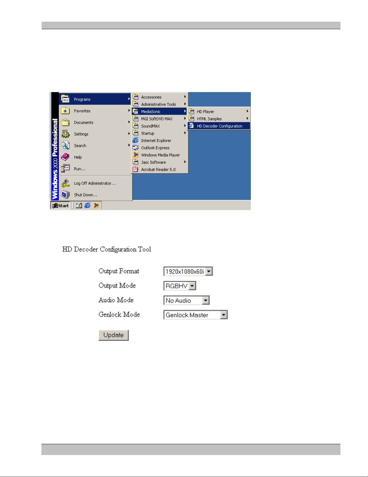
You may implement specific HD Player settings from the HD Decoder Configuration window.
From the Start menu select Programs/MediaSonic/HD Decoder Configuration, as shown in the following
graphic:
The following dialog appears as part of the HD Decoder Configurations display. Make any necessary changes to
optimize the performance of the Media Player.
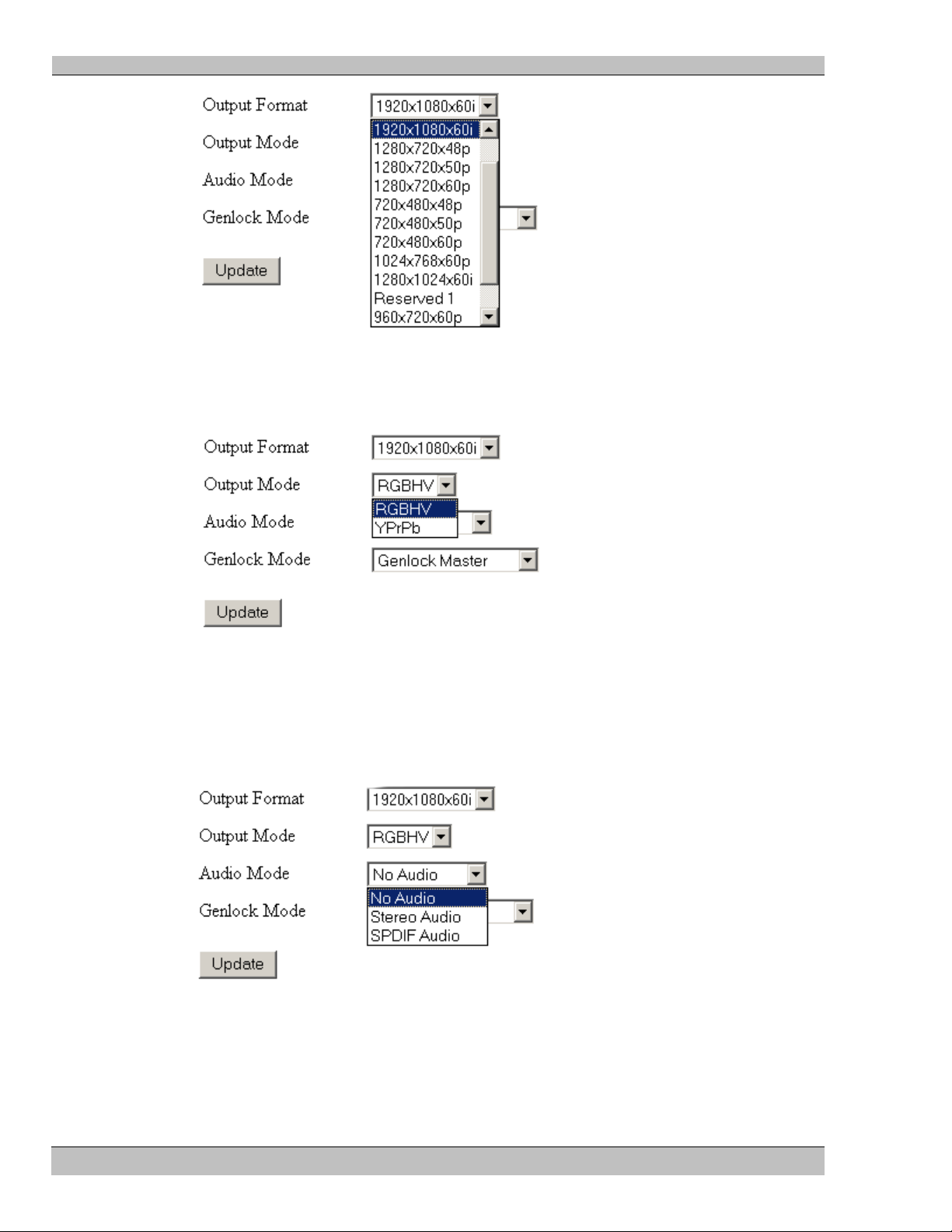
Output Format
Match your MS9100D HD Player video output format to the display device:
25 Rev. 6.8
Page 26
HD Player Chapter 2: The Playlist display
Output Mode
Select video output mode from the two available:
Audio Mode
Stereo Audio is the default mode. Choose SPDIF Audio for 5.1 surround sound or No Audio if required.
Note: Stereo Audio makes use of the player’s sound card audio output. 5.1 surround sound is available at the
SPDIF connector. (Refer to the Figure 3)
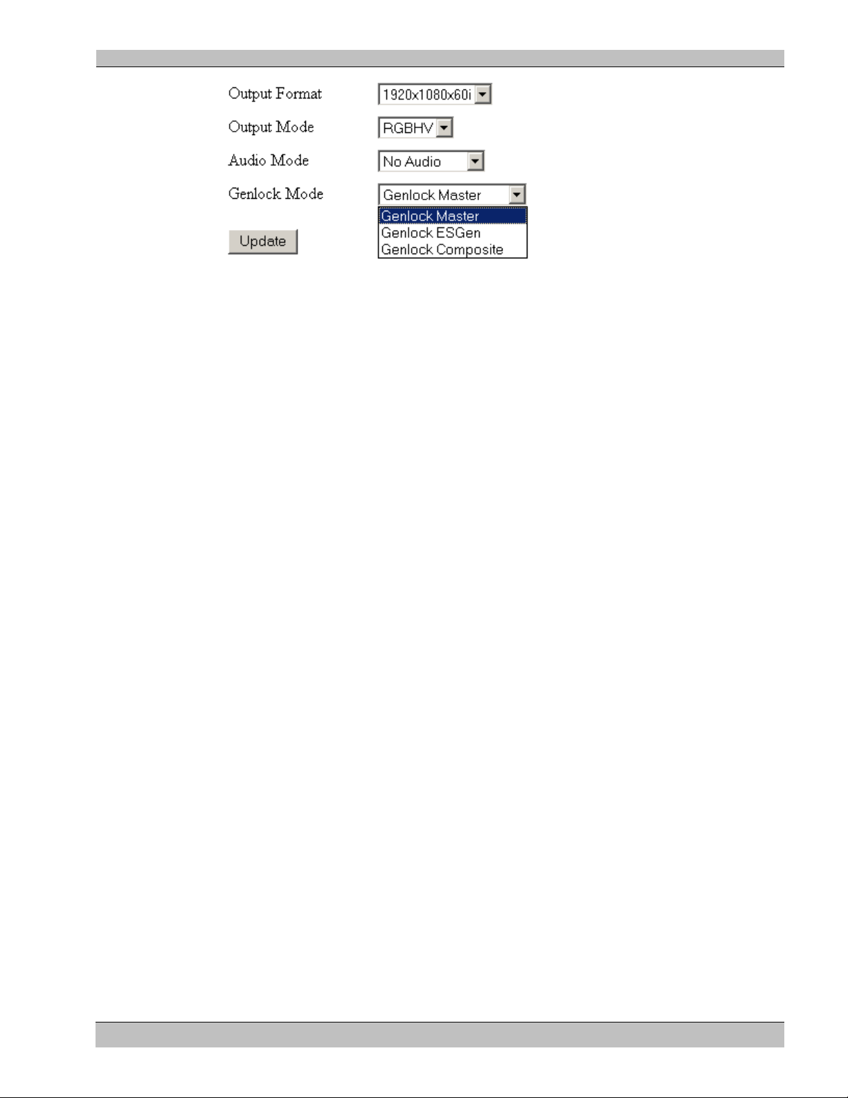
Genlock Mode
Chose your video synchronization option from the drop down menu.
Note: ES-Gen is not available on the MS9100D model.
26 Rev. 6.8
Page 27
HD Player Chapter 2: The Playlist display
Update
Select the Update button to save your settings after you have made any changes.
27 Rev. 6.8
Page 28
HD Player Chapter 2: The Playlist display
Clip
Chapter
Chapter 2: The Playlist Display
The Playlist
Use the Playlist area of the HD Player GUI to perform MPEG clip management functions:
• Display and select clips which have been previously loaded on the HD Player’s disk drives
• Add new clips
• Copy clips
• Set up clip sequences to run in a particular order. The order may be changed by simply dragging the clip
to a new position within the sequence
The Playlist also allows access to many of the powerful features and settings of the HD Player, namely:
• The Clip Properties Dialog – This dialog controls Clip specific configurations
• The Channel Properties Dialog – This dialog controls system configurations
The functions of these dialogs will be described in detail later in this manual.
Note: After Editing the Playlist or any of the Dialogs mentioned above, you must save the configuration to ensure
the Playlist is available when the HD Player is next restarted. See Chapter 10:“Configuration Files” for more
details.
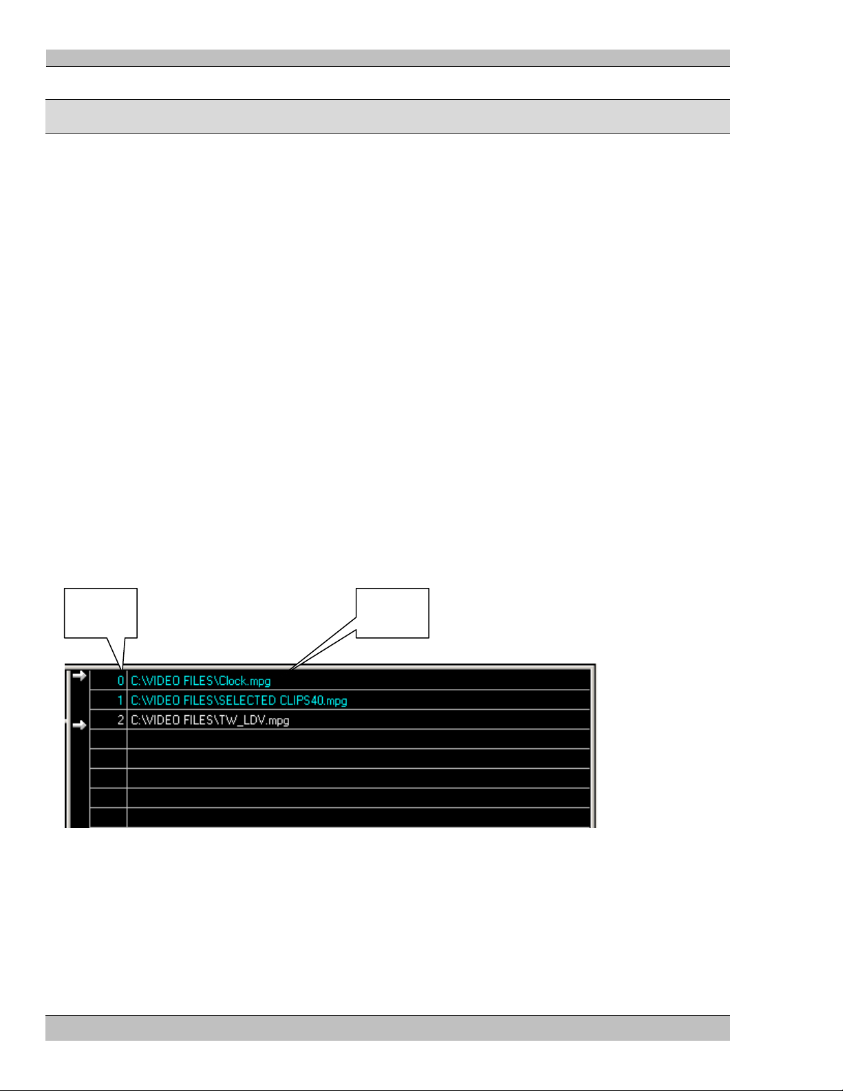
The following figure defines the data that appears in the Playlist.
Number.
Name.
Adding a clip to the Playlist
There are two methods that can be used to add clips to the Playlist.
• Double Click a blank entry in the Playlist. This will produce the Clip Properties dialog box, from which
an MPEG file can be selected. The Clip Properties dialog is described in a separate section below.
28 Rev. 6.8
Page 29
HD Player Chapter 2: The Playlist display
• Drag and Drop: Open an explorer window, select one or more files and drag them onto the Playlist. As
the mouse is moved over the Playlist area, a highlight bar will appear indicating where the files will be
placed.
You may re-order clips in the Playlist at any time, simply drag files to different positions within the Playlist as
necessary.
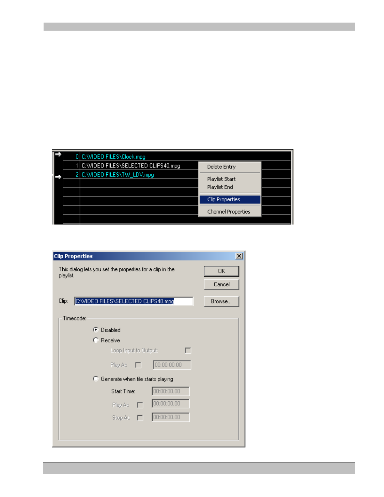
The Clip Properties Dialog
The Clip Properties dialog box is used to set various parameters relating to the clips in the HD Player Playlist.
Open this dialog window by right clicking over a clip in the Playlist, and selecting the “Clip Properties” menu
item.
The Clip Properties dialog appears, as shown below.
29 Rev. 6.8
Page 30

HD Player Chapter 2: The Playlist display
The various fields in this dialog are described below.
Clip name
The clip name specifies the location and name of the MPEG transport file.
• Click the Browse button to display a standard file selection window that can be used to locate the required
file.
Timecode
This section provides a number of control options for using the HD Player in a Timecode aware system.
Note: For full details on how to use these options please refer to Chapter 6: Timecode.
30 Rev. 6.8
Page 31

HD Player Chapter 2: The Playlist display
Selecting and Playing a Clip
To Play a Clip
1. Double click any clip in the Playlist, this will Cue the start of the clip
2. Click
3. Click
take a few seconds), next click
(Play) button on the Transport to begin playing the clip.
(Pause/Stop) button to quit or click , the HD Player will re-cue the clip (this may
to restart the clip.
Alternately yo u may :
1. Drag both arrows at the left of the Playlist up or down to the clip you wish to play
2. Click the
3. Click the
(Cue) button on the Transport
(Play) button on the Transport to begin
Selecting and Playing a List (Sequence)
1. Drag a Pointer at the left of the Playlist to the beginning clip of the sequence
2. Drag the remaining pointer at the left of the Playlist to the end clip of the sequence
3. Place intermediate clips in any order you wish by dragging to their required position in the order. If only
two files make up the Playlist, the first file to be played will be the first file listed.
4. Click the Cue button on the Transport Control
5. Click the Play button in the Transport Control
Note: Please refer to Chapter 3: Transport & Status displays for more details regarding the play, cue and other
clip control features
31 Rev. 6.8
Page 32

HD Player Chapter 3: Transport & Status displays
Transport
Frame
Current
Current
Mode
No Longer Supported
Transport
Cue To
Slider
Chapter 3: Transport & Status displays
The HD Player interface is similar to that of a simple tape player: The tape is played until it reaches the end, when
a rewind is required to play again. In the case of the HD Player this rewind (Cue) is near instant, but the metaphor
provides a useful description.
The Status display is linked to the Transport Controls and shows various pieces of useful information about the
current state of the HD Player.
Status
Indicator
+ Output
Mode
Buttons
Counter
Timecode
Chapter
and File
“Confidence Display”
Transport status
The transport status shows the current operating state of the HD Player. The display will show one of the
following messages.
Stopped
The Stopped indicator appears at Start-up of the HD Player software, only. The status will change when the first
file is cued.
32 Rev. 6.8
Page 33

HD Player Chapter 3: Transport & Status displays
Paused
The Paused indicator is displayed under the following circumstances.
• Paused will be shown after a file has been cued.
• Paused will be displayed if a file has been played and then stopped using either the transport controls or a
remote control message.
Cueing
The Cueing indicator will be shown when
• The cue button has been selected from the transport controls
• The user double-clicks a clip in the Playlist – selecting the Play button will run the cued clip
• A play range command has been received through a remote control interface.
During the cueing process, the HD Player searches the MPEG clip for the first displayable picture and initializes
the video output to the requested resolution. The Cue process ensures that when a play command is received the
MPEG decoder is primed and ready to play. This is essential in multi-channel systems where a predictable startup
is a requirement.
Playing
The playing indicator will be displayed while the HD Player is decoding the MPEG stream (an image of the
playing clip will appear within the HD Player GUI).
Frame Counter
The frame counter shows the current clip position in hours, minutes, seconds, frames.
Note: This number is relative to a start frame of 0, i.e. the first frame decoded in the MPEG stream will be shown
as 00:00:00:01
Current Timecode
This display shows the current Timecode in the following configurations:
• If the HD Player is set to generate mode, this window will show the current value at the Timecode output.
• If the HD Player is set to receive mode, this window will show the current incoming Timecode value.
Note: Refer to Chapter 6 for more detail on Timecode
Mode Indicators
The Mode indicators are used to illustrate various on/off style settings on the HD Player. These modes are..
33 Rev. 6.8
Page 34

HD Player Chapter 3: Transport & Status displays
Loop
This indicator will be on when the Auto-repeat mode is selected. The auto-repeat mode can be selected
from the transport controls. When this option is set and the decoder reaches the end of an MPEG clip,
playback will continue from the first frame of the MPEG clip. This ensures continuous playback.
Note: The visual quality of the loop is dependent on how the MPEG stream ends. For full details of how
to ensure clean looping, please refer to the encoding considerations later in this manual.
Vid
This indicator will be on if the video output is active. It will be off when the video outputs are muted
(black). Video syncs are maintained while in muted mode. The HD Player on-screen monitor is not
affected by the muted option – it does however affect the primary, secondary and HDSDI outputs.
Aud
This indicator will be on if the audio output is active. It will be off when the audio is muted. Audio mute
will mute both the SPDIF and Stereo audio.
Current Chapter and Clip Name
The Current Chapter field indicates the name of the file that is currently selected for playback. This entry will
change as a result of the cue command.
Note: The term Chapter refers to a file in the Playlist. The meaning is analogous to the term used in reference to
DVDs. Here chapter refers to a section of the disc.
Transport/Output Controls
Cue
Pause
Auto-repeat (Loop)
Play
This button is used to start the Clip playing.
This button is used to pre-load a clip from the Playlist or to
“rewind” a clip to the beginning prior to a restart.
This button is used to stop the Clip playing.
This button is used to toggle the auto-repeat mode on or off. When
this option is selected, a playing file will restart from the
beginning when it reaches the end.
Audio Output
34 Rev. 6.8
Page 35

HD Player Chapter 3: Transport & Status displays
This button is used to toggle the audio output on or off.
Video Output: Black
This button is used to mute (set to black) the video output.
Video Output
This button is used to activate the Video output, following either a
video mute, or color bars command
Color Bars
This button is used to display color bars on the video outputs.
Fast Forward/Loop Slider
• Drag this Slider to Cue to any position in a clip. Click the Play button to play from the new position.
Confidence Display
• No longer supported.
35 Rev. 6.8
Page 36

HD Player Chapter 4: The Log/ File Information Windows
Click here to select the
Log Window
File Info. Window
Chapter 4: The Log / File Information Windows
The Information display at the bottom of the GUI is divided into two (left and right) main segments:
• The Log Window on the left, and
• The File Information Window on the right
• Additionally, the Status Bar is located at the very bottom left of the display
These windows display various pieces of useful information about the HD Player while it is running. The
information shown can be used to “debug” show control programming problems, check communications protocols
and generally monitor the condition of the HD Player.
The Log display is arranged as a set of “pages” each listing related information. The active tab, i.e. the one whose
entries are being displayed, can be selected by clicking over it’s name, as illustrated in the following diagram.
Stream Errors Tab
The Log W indow
The Log Window displays various Log Tabs:
• Main - Shows details about the unit’s status, such as when files are cued and played, when the audio or
video is muted etc.
36 Rev. 6.8
Page 37

HD Player Chapter 4: The Log/ File Information Windows
User Defined Tab
• Stream Errors – Lists any errors in the MPEG stream, useful for troubleshooting.
• Text Command Protocol (User Defined) – This is a remote control connection through server Port 23. A
log tab “RemoteCon” for example is created for each remote control method defined by the user. These
tabs display any commands received by that method and will also show any protocol errors encountered.
(See Chapter 11: Remote Control Configurations, also, Chapter 12: Remote Control Protocols)
The File Information Window
The File Information Window displays various properties unique to the current clip:
• Properties – Data Rate of the clip
• Video – Horizontal and Vertical Resolution, Frame Rate and PID
• Audio – Sample Rate, Channels, Format, Bit Rate and Frame Time
Click the appropriate tab to view the page contents.
37 Rev. 6.8
Page 38

HD Player Chapter 4: The Log/ File Information Windows
The Status Bar
The Status Bar lists information about the main menu commands. Use the Status Bar for quick tips about the
commands available on the main drop down menus. The display changes as you drag your pointer along the menu
options.
To turn the Status Bar on or off:
1. Click View on the main menu
2. Click the Status Bar icon: Checked – On, Unchecked – Off.
38 Rev. 6.8
Page 39

HD Player Chapter 5: HD Player Configuration
Chapter 5: HD Player Configuration
The HD Player Software provides a number of configuration options that can be used to control the Player’s
functionality. These options cover the output signal format, startup behavior and other features that are set once
and not changed as part of the show control system.
To Modify the Player Configuration
• Right-Click the Playlist area and select Channel Properties from the drop down menu.
The Channel Properties dialog
The Channel Properties dialog box appears (shown below), containing a number of different settings necessary for
optimum performance of your HD Player.
Note: You must select Save from the File/Save menu to keep any changes made in the Channel Properties dialog
39 Rev. 6.8
Page 40

HD Player Chapter 5: HD Player Configuration
Set the channel to loop at startup
This option determines the state of the auto-repeat (loop) function at HD Player power on. Select this option by
clicking the box. The HD Player will be set in auto-repeat mode at the end of the currently playing clip.
Set the channel to start playing at startup
This option instructs the HD Player to play a file when it is first powered on. When the option is selected the clip
that was in use when the configuration file was last saved will play at startup. For more information please refer to
the Configuration files section of this manual.
Video on at startup
Select this option to enable HD Video output when the HD Player is powered on. This option will usually be set,
but can be useful in certain show control environments.
Audio on at startup
Select this option to enable the HD audio output when the HD Player is powered on. This option will usually be
set, but can be useful in certain show control environments.
Output black when file completes
Select this option to set the HD Player video output to black whenever a clip completes. This is useful for theater
style applications, where the MPEG clip may end on a bright picture, which would stay on the screen until the
next play command is sent. A black output will avoid any possible “burn in” problems on certain display devices.
40 Rev. 6.8
Page 41

HD Player Chapter 5: HD Player Configuration
Enable AV Sync
Select this option to allow the HD Player Software to force synchronization between audio and video during
playback.
A typical MPEG file consists of a separate audio and video stream played back together. The MPEG specification
contains extensive time-stamping mechanisms to ensure that during playback the audio and video remain
synchronized The Electrosonic HD Player has built in logic to process time-stamps within an MPEG stream and
use these timestamps to actively synchronize the video to the audio
The “Enable AV Sync” option can be used to enable or disable the synchronization algorithm. When the option is
unchecked the audio and video streams are decoded without regard for each other. This will result in solid and
stable video and audio playback but they may drift apart relative to each other – particularly during looping.
When the option is checked the synchronization algorithm is employed and any time-stamp discrepancies are
eliminated.
Base Channel Number
Set this number to identify a specific HD Player (for remote control purposes) in a system utilizing multiple HD
Players. Default is 1.
Enter the appropriate Base Channel Number into the Text Command Protocol command structure – refer to
Chapter 12, Remote Control Protocols for more information.
Audio Output Format
The HD Player supports three different audio output modes, which can be selected from a drop down list. To
change the audio output mode, click over the window and select the required setting.
No Audio Decode
This mode will disable the audio decode.
Select this option when the HD Player is used in a system environment, where the audio is provided by an
external, timecode locked, digital audio playback device.
Output Stereo
Select this mode to use the built in AC3 audio decoder and output the two primary channels in the stream through
the stereo audio jack.
Output AC3 – SPDIF (5.1)
Select this mode to utilize the SPDIF output on the Electrosonic Decoder Card.
When this mode is selected the AC3 audio in the MPEG file is embedded inside an SPDIF (IEC-61937 formerly
IEC-958) digital signal. This mode requires an external Dolby Digital® decoder to interpret the digital stream.
For more information on SPDIF please see the appendix at the end of this manual.
Output Standard
The HD Player supports two different output formats, which can be selected from a drop down list. To change the
output format, click over the window and select the required setting.
Output RGBHV
41 Rev. 6.8
Page 42

HD Player Chapter 5: HD Player Configuration
This mode is similar to a Computer graphics output. This is a five wire signal, with separate lines for the Red,
Green, and Blue colors, and the horizontal and vertical syncs.
Output YPrPb
This mode is a three-wire component signal, with horizontal and vertical syncs combined on the Y channel. This
format conforms to the ATSC High Definition video specification.
Genlock
The HD Player supports three different genlock modes, which can be selected from a drop down list. To change
the genlock mode, click over the window and select the required setting.
Refer to Chapter: 8 for a more detailed description of using the genlock modes in various system configurations.
Genlock Standalone/Master
Select this mode when the HD Player is operating as a standalone unit or is used as the genlock master in a multichannel HD Player system.
Genlock ES-Gen (MS9200P only)
Select this mode when using the HD Player with a proprietary Electrosonic genlock feed – referred to as ES-Gen.
This signal mode is typically used in a multi-Player setup, such as a 3D presentation.
Genlock Composite Black Burst
Select this mode to genlock the HD Player to a composite black and burst signal.
Ensure that the genlock signal matches the output standard selected. For example it is not possible for the HD
Player to genlock to a PAL composite signal if the output mode is set for a 60Hz output mode.
Advanced
A Video Confidence Display (No Longer Supported) that appears in the HD Player GUI. Some occasions may
warrant that the Video Confidence Display facility be turned off without removing or changing the settings.
To turn off the Video Confidence Display
1. Select the Advanced Properties button in the Channel Properties dialog
2. Check or un-check the box to turn the display On or Off .
Note: This setting does not affect the HD Player video outputs.
42 Rev. 6.8
Page 43

HD Player Chapter 5: HD Player Configuration
Click to select the required
Click to select the required
Click here
BCS – Brightness-Contrast--Saturation
Refer to Chapter: 9 for details on BCS adjustment.
Overlap (Soft Edging or Edge Blending)
Refer to Chapter: 7 for details on Overlap.
Output Format
Use this feature of the Channel Properties to ensure that your Video format matches the requirements of your
display device.
Note: Changes made in the Output Format window only affect the video output and will not be seen on the GUI
confidence display
The video Output Format field tells the HD Player how to format the video output. Normally this will match the
contents of the file. A file encoded as 1080i is normally decoded as 1080i, but the HD Player has an integrated
video scaler that can output a different format to that contained in the file. Setting this option to unknown will
cause the Video output to keep its current format.
To select the required format, click over the down arrow and select the required setting from the drop down list.
Video output format.
43 Rev. 6.8
Video output frequency.
Page 44

HD Player Chapter 5: HD Player Configuration
Format
Frequency
Notes
1920x1080i
23.98 (sF) Hz
1280x720p
48 Hz
720x480p
48 Hz
960x72op
59.94 Hz
1024x768p
59.94 Hz
This mode was designed to match the resolution of many digital display
1280x1024i
60 Hz
As above
1440x1080i
59.94 Hz
1600x1200i
24 (sF) Hz
Reserved1
This mode is for internal test only and should not be selected.
The following table illustrates the formats supported. Some of these are not standard ATSC video modes, and are
custom to the Electrosonic HD Player.
24 (sF) Hz
48 Hz
50Hz
59.94 Hz
60 Hz
50Hz
59.94 Hz
60 Hz
50Hz
59.94 Hz
60 Hz
Commonly referred to as 1080i
Commonly referred to as 720p
Commonly referred to as 480p
devices (such as DLP or LCD). This gives very good quality images because
it removes the need for the projector to resize the input signal
59.94 Hz
44 Rev. 6.8
Page 45

HD Player Chapter 6: Timecode
Chapter 6: Timecode
Large control systems often require a number of different, and usually diverse, pieces of equipment to operate
within strict timing constraints. For example, an exhibit may use a video display with an associated multi-channel
audio playback system. A method is required to ensure that the audio playback matches the video display. This is
often referred to as “Lip Sync”.
This synchronization problem can be solved using a Timecode signal. Timecode, as the name suggests, is a stream
of coded time stamps encapsulated in an audio signal. The frequency of these time stamps is designed to match
video rates for the various video standards in use around the world. There are three common standards in use
today.
SMPTE - The SMPTE standard is used in the USA and matches the video rate of 29.97 frames per second.
EBU – This standard matches the PAL specification in use in the United Kingdom, i.e. 25 frames per second.
FILM – This standard matches the 24 frames per second used in the motion picture industry.
A typical timecode based system will incorporate a device that generates the timecode for the system, referred to
as the master timecode. This signal is distributed to each timecode aware device in the system. These are often
referred to as slaves. A slave will usually have the ability to generate its’ output based on the timecode it receives.
For example a lighting system could be programmed to generate a lighting scene or effect when a certain timecode
is received.
The Electrosonic HD Player can operate either as a slave or as a master. This allows for maximum flexibility
when integrating the Player in a system. It is even possible for some clips to operate in the master mode while
others operate in the slave mode.
Note: Drop Frame timecode is not supported.
Configuring as a Timecode Master
In the master mode the HD Player is programmed to generate timecode when an MPEG clip begins playing. This
allows any slave devices to be locked to the video output from the Player. Each clip can have its own unique
timecode and has the ability to generate a pre-roll and/or run-on option.
The Timecode configuration dialog
To access the timecode configuration dialog:
1. Right click over an entry in the clip list
2. Select “Clip Properties” from the drop down menu.
3. Select the Generate option in the properties to set the parameters.
45 Rev. 6.8
Page 46

HD Player Chapter 6: Timecode
Click here
Note: A Clip has to be cued using the transport controls or a remote control message for the timecode settings to
be activated.
Start Time
This is the timecode that will be generated when a play command is received after the clip a cued. If the Play At
(see below) option is not enabled, this will also be the point when video output begins. The HD Player will output
this timecode, as a “Jam Sync” signal, when a cue command is issued.
Play At
Select the Play At box and enter a time to set a pre-roll, i.e. a period where timecode is generated before the video
starts. This might be used for pre show setup before the video begins.
46 Rev. 6.8
Page 47

HD Player Chapter 6: Timecode
Stop At
Select the Stop At option set a stop point for the timecode. This time can be before or after the end of the video
output. This might be used for controlling “post show” equipment such as fading house lights up. The Stop At
time is independent of the length of the MPEG clip. Stop At can be used to stop the timecode while the clip is still
playing, or extend the timecode after the clip has ended.
The following examples show some typical uses of the timecode generation options:
Generate a timecode starting at 01:00:00:00 when the play command is received.
Generate a timecode starting at 01:00:00:00 when the play command is received, but delay start of the
video playing until 01:00:10:00.
Generate a timecode starting at 01:00:00:00 when the play command is received. Start the video 10
seconds later (10 second delay) and run the timecode on until 01:05:00:00.
47 Rev. 6.8
Page 48

HD Player Chapter 6: Timecode
Configuring as a Timecode Slave
In the slave mode the HD Player can be programmed to start playing when it receives a particular timecode. A
different timecode can be programmed for each clip in the clip list.
To access the timecode configuration right click over an entry in the clip list and select “Clip Properties” from the
drop down menu. Select the Receive option in the properties to set the parameters
Play At
The Play At box is used to set the trigger point at which the cued file will begin playing.
Loop Input to Output
Select this option to pass incoming timecode through to the timecode output. Use this feature to daisy chain a
number of HD Players to the same timecode input.
Note: In the loop through mode the output timecode is electrically regenerated, i.e. there is no perceptible delay in
the timing between the input and output.
The following example shows a typical use of the timecode receive option:
Play the clip when a timecode of 01:00:10:00 is received.
48 Rev. 6.8
Page 49

HD Player Chapter 6: Timecode
In this mode a cue command is required for the timecode trigger to be activated.
Configuring as a Timecode Reader
The HD Player can also be used as a simple timecode reader if verification of incoming timecode is necessary.
Simply select the Receive mode but do not check the Play At option. In this mode the Timecode window will
show the incoming timecode without a clip being played.
Timecode Cable
In the event that you must fabricate your own Timecode cable(s), use the information in the diagram below:
49 Rev. 6.8
Page 50

HD Player Chapter 7: Soft Edging/Display Overlap
Chapter 7: Soft Edging/Di s play Overlap
The following techniques can be employed to produce high resolution, high brightness displays:
Videowall
The term videowall refers to an image built up by stacking display devices. A Videowall typically uses a complex
digital video processor to split an incoming video source into the multiple outputs sent to the display.
Videowalls offer a very high brightness, high-resolution display in a small physical space. They do, however, have
the negative characteristic that the borders (called mullions) between each display segment are visible and often
distracting.
Single Projector
If space is available in front of, or behind the screen, a single projector system can be used to fill the display with
a single image. The display resolution is limited to the resolution of the projector. Projectors capable of delivering
a large bright image also require expensive and fragile lamps that typically have a limited life.
Introducing Soft Edging
Soft Edging or “Display Overlap” is a technique for generating a single image on a screen when using multiple
projectors. This results in a seamless display that shows no signs of being made up of spliced-together images
from separate projectors.
A soft edged display provides the benefits of both the Videowall and the Single Projector with few of their flaws.
Multiple projection systems allow the designer to utilize smaller and less expensive projectors to display an image
on the same screen area that would otherwise require a single larger and more expensive projector. This technique
achieves greater total pixel resolution and more brightness (lumens), at a lower cost.
Achieving a soft-edged display is a two-step process.
1. Overlap part of the image from each projector with its neighbor in order to ensure a seamless display. A
typical installation would require 5% of the image to be in the overlap.
2. Adjust the video output in the overlap to correct for the “doubling” of light output that occurs in the
overlap region between adjacent projectors. The HD Player utilizes sophisticated digital processing to
implement this brightness adjustment.
The following illustration gives an example of a three projector wide display showing the overlap concept (The
projectors are identified as #1 – Left, #2 - Center and #3 – Right, when viewed from the projection location)
50 Rev. 6.8
Page 51

HD Player Chapter 7: Soft Edging/Display Overlap
The Electrosonic HD Player can be configured to provide luminance and/or chrominance adjustment to the
overlapped section of the image, thus compensating for the increase in brightness in this area of the screen. This
adjustment is termed Soft Edging control, and provides electronic manipulation of the image in both the horizontal
and vertical axis.
Note:
1. Soft Edging is available only on the Secondary analog (H D2) and HDSDI outputs of
the MS9200P HD Player.
2. Soft Edging is not available on the Primary analog output (HD1) of the MS9200P HD
Player.
3. Soft Edging is not available on the HD output of th e M S 9100P or MS9100D HD Players
4. Best performance with Soft Edging is achieved when using the Y.Pr.Pb mode.
51 Rev. 6.8
Page 52

HD Player Chapter 7: Soft Edging/Display Overlap
Configuring a Soft Edged System
To access the Soft Edging control, right-click anywhere in the Playlist window. Select Channel Properties from
the drop down menu.
In the Channel Properties dialog box select the Overlap button.
52 Rev. 6.8
Page 53
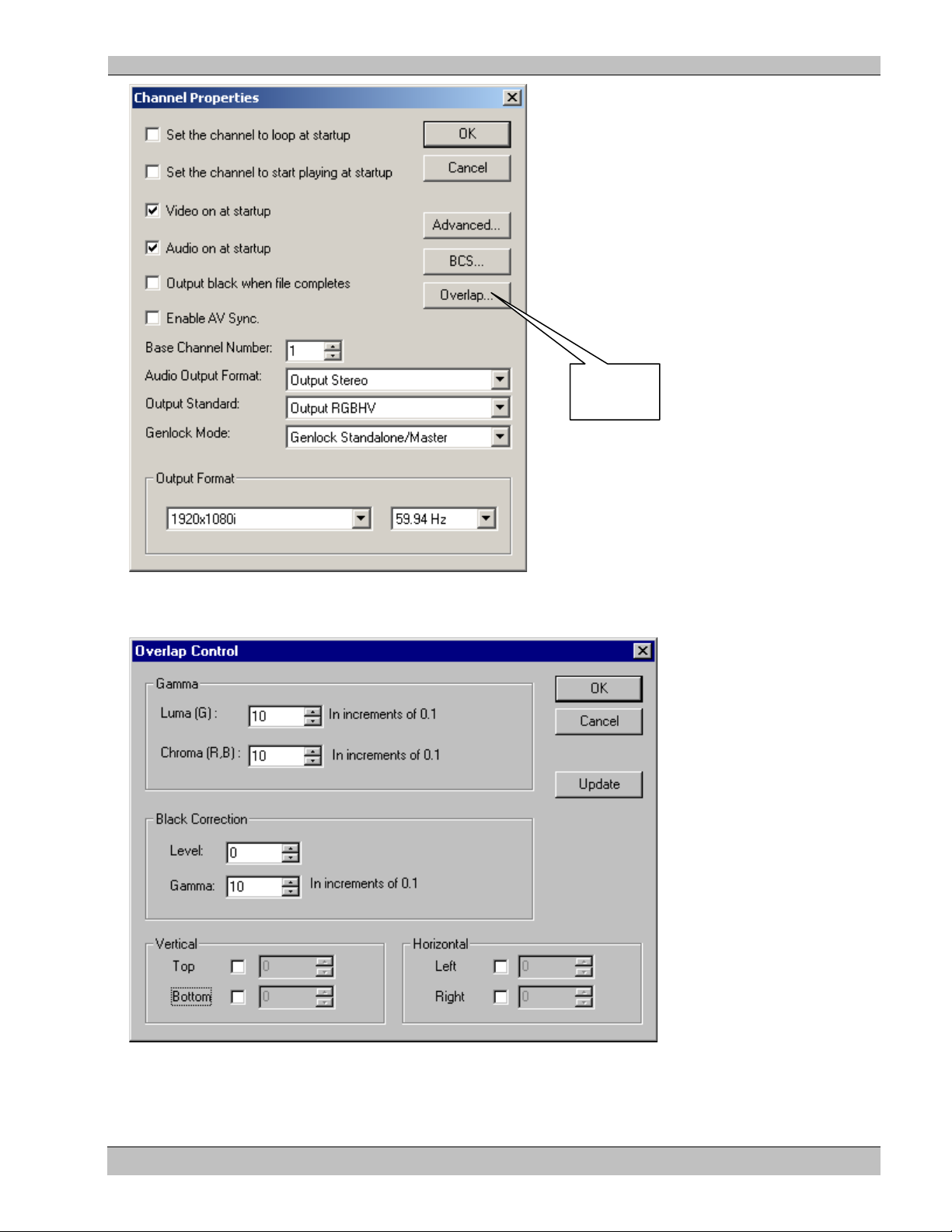
HD Player Chapter 7: Soft Edging/Display Overlap
Soft Edge
Control
This will open the Overlap Control Dialog box.
The following sections describe the various parameters that can be controlled.
53 Rev. 6.8
Page 54

HD Player Chapter 7: Soft Edging/Display Overlap
Overlap set to 100 for
Vertical and Horizontal Borders
To define the vertical and/or horizontal borders for Soft Edging:
1. Enable the borders required by selecting the appropriate check box.
2. Enter the amount of overlap. This can be set from 1 to 255 in both horizontal and vertical axes. If both
borders in an axis are used, they must be set identically.
The following example shows settings for the center screen of the 3 x 1 projection system (shown previously) with
a 100 pixel overlap on both left and right edges.
both left and right edges
The Overlap Control Dialog for each of the other two projectors is set up identically except:
Set Projector #1 (Left), as shown below.
Set Projector #3 (Right), as shown below.
54 Rev. 6.8
Page 55

HD Player Chapter 7: Soft Edging/Display Overlap
Gamma
Once the borders have been defined, the next requirement is to determine the rate of change that occurs to the light
level during the transition between the start of the overlap, to the non–overlapped part of the image. This can be
thought of as ramping the image from 0% brightness to 100% brightness.
In its simplest form, this ramp is linear (gamma value of 1.0) as illustrated above. However, the light output of a
projector does not have a linear relationship to input voltage and so a gamma correction must be applied to the
ramp to compensate.
The following diagram illustrates a gamma corrected brightness curve.
The HD Player produces two independent curves for each output mode:
1. In the YPrPb output mode there is one for Luma (Luminance) and one for Chroma (Chrominance).
2. In RGB color space the green output has its own curve, and Red/Blue share the other curve.
55 Rev. 6.8
Page 56

HD Player Chapter 7: Soft Edging/Display Overlap
Typical gamma settings are between the values 1.6 – 2.8 although this will vary depending upon the
projector/lamp used. The actual value will be determined during projector alignment.
The following example shows a Luma and Chroma gamma setting of 2.2.
Note: The Gamma units are displayed in 0.1 increments in the Overlap Control dialog window.
56 Rev. 6.8
Page 57
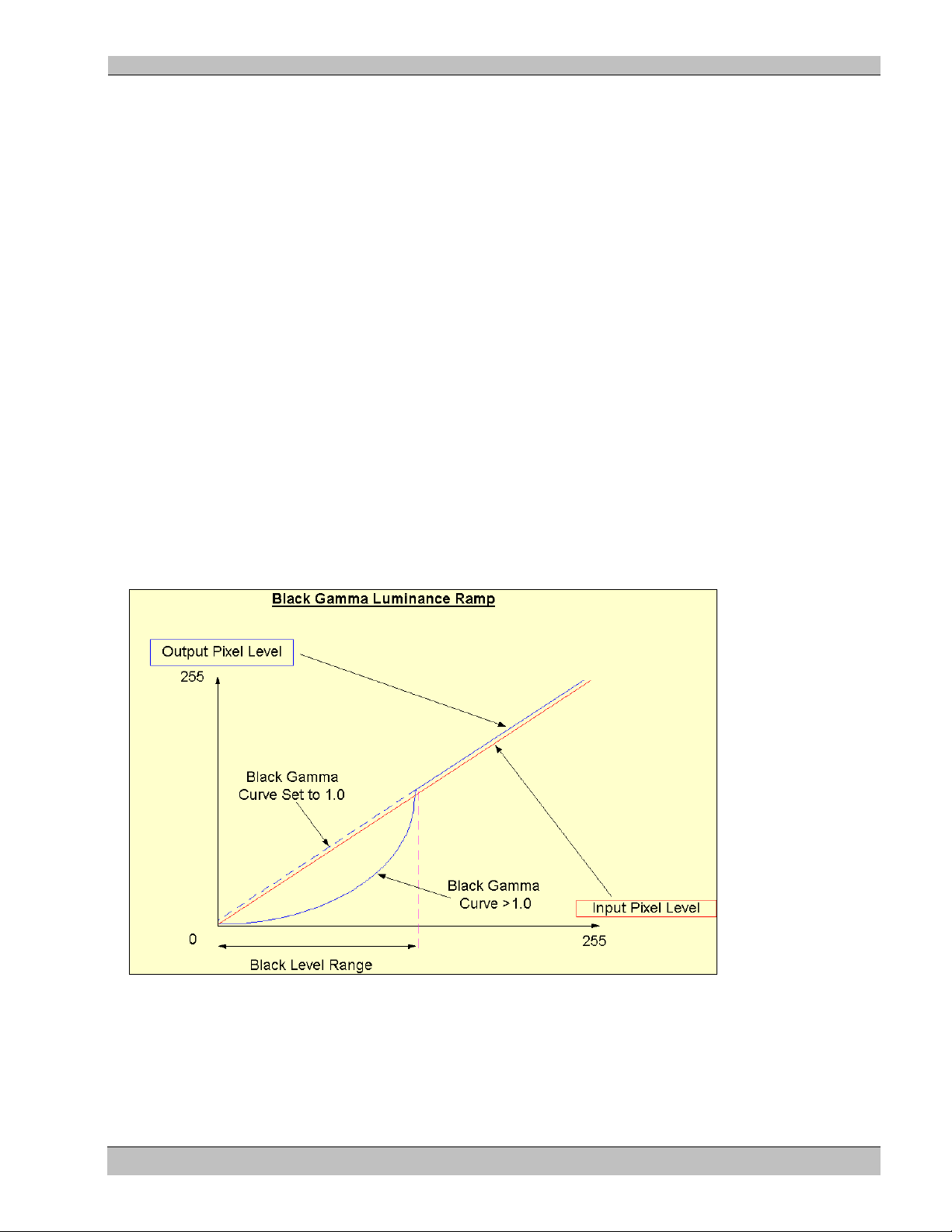
HD Player Chapter 7: Soft Edging/Display Overlap
Black Correction
This feature is only available in YPrPb Color Space.
Certain projectors are unable to output a true black level, where black equals no light. This can present a problem
when using soft edging with dark scenes, where the black levels can be elevated into grays.
The Electrosonic HD Player can modify the pixel values for dark images using a “blacker than black” gamma
adjustment.
This feature must be used in conjunction with the Brightness and Contrast control described in the following
section.
Before adjusting the black correction level, the signal brightness must first be elevated using the Brightness
control as described in the BCS section. This ensures an amount of “headroom” for the black level to work within.
Note: The Contrast setting may require adjustment if the image appears to be crushing the whites.
Two Black Level controls are provided:
1. Level - This determines the highest Luminance pixel value starting from 0 that can be modified by the
black gamma curve. Range is 0 –255, but in practice only values below 70 should normally be used.
2. Gamma - Similar to the main Chroma / Luma curves, this determines the amount of black adjustment
that is applied to the input pixel. A value of 1.0 results in a linear ramp (no adjustment).
The following example shows a Black Level gamma curve of 3.0 operating on luminance pixels which contain a
value of 50 or less.
57 Rev. 6.8
Page 58

HD Player Chapter 7: Soft Edging/Display Overlap
Update
Click the Update button to download these settings at any time during the adjustment of the Gamma and Overlap
parameters. A picture disturbance will be observed while the update is in progress; a normal picture will resume
after the settings have been updated.
Note: It is not necessary to re-cue a file to change any of the overlap parameters.
58 Rev. 6.8
Page 59

HD Player Chapter 8: Genlock
Click here to select
Chapter 8: Genlock
The Electrosonic HD Player can be configured to operate in a number of different Genlock configurations.
Genlock provides a method for ensuring that multiple HD Players can operate with synchronous timing on each of
their outputs. Also, the playback timing of each of the Players in a genlocked system will ensure that the first
frame of video is decoded across multiple Players at the same time.
Note:
MS9200P – ES-Gen Genlock and/or Composite Video Black & Burst sync available
MS9100P – Composite Video Black & Burst sync available only
MS9100D – Composite Video Black & Burst sync available with optional MS9000 HD Player software
Genlock Mode
The Player can operate in one of three genlock modes chosen from the Genlock Mode drop down menu in the
Channel Properties dialog box.
Within the Channel Properties Dialog window click on the arrow button indicated below:
Genlock Mode.
59 Rev. 6.8
The Genlock Mode menu shown below will appear:
Page 60

HD Player Chapter 8: Genlock
GENLOCK STANDALONE/MASTER
MS9200 HD PLAYER
MS9200 HD PLAYER, GENLOCK ESGEN
MS9200 HD PLAYER, GENLOCK ESGEN
HD-1 HDSDI HD-2
OUT IN
MS GENLOCK
CVBS SPDIF IN OUT
TIMECODE
HD-1 HDSDI HD-2
OUT IN
MS GENLOCK
CVBS SPDIF IN OUT
TIMECODE
HD-1 HDSDI HD-2
OUT IN
MS GENLOCK
CVBS SPDIF IN OUT
TIMECODE
GENLOCK IN
GENLOCK IN
GENLOCK OUT
6 WAY MALE,
MINI DIN CABLE
6 WAY MALE,
MINI DIN CABLE
GENLOCK OUT
Select a Genlock Mode depending on your system configuration.
Genlock Standalone/Master
Select this mode when the HD Player is operating as a standalone unit or is used as the Genlock Master in a multichannel ES-Gen HD Player system.
Genlock ES-Gen
Select this mode to lock the HD Player to the proprietary Electrosonic Genlock feed – referred to as ES-Gen. This
mode of Genlock is normally used in small systems where an external house Sync or Video Black and Burst
signal is not available. We recommend that this system of Genlock be restricted to a maximum of 3 HD Players in
a “daisy chain”.
To set up an ES-Gen system:
1. Set the Master HD Player in Genlock Standalone/Master mode
2. Set all slave video Players to Genlock ES-Gen mode
The figure below shows a typical ES-Gen cabling configuration.
60 Rev. 6.8
Page 61

HD Player Chapter 8: Genlock
1
1
2
2
3
3
4
4
5
5
6
6
6-Pin
DIN, Male
4 Twisted pair CAT5 cable
(use 6 of 8 conductors)
PINOUT
6-Pin
DIN, Male
1
3
5
2
4
6
MS9200 HD PLAYER, GENLOCK COMPOSITE BLACK/BURST
MS9200 HD PLAYER, GENLOCK COMPOSITE BLACK/BURST
MS9200 HD PLAYER, GENLOCK COMPOSITE BLACK/BURST
HD-1
HDS
DI H
D-2
OUT IN
MS
GE
NLO
CK
C
VBS SPDI
F IN OUT
TIMECODE
HD-1 HDSDI HD-2
OUT I
N
MS
GENL
OCK
CV
BS S
PDI
F IN O
UT
TI
MEC
ODE
HD-1 HDSDI HD-2
OUT
IN
MS
GEN
LOC
K
C
VBS
SPD
IF IN
OUT
T
IMEC
ODE
CVBS IN (BNC CABLE)
CVBS IN (BNC CABLE)
CVBS IN (BNC CABLE)
COMPOSITE VIDEO BLACK BURST GENERATOR
Genlock Cable
Use cables provided by Electrosonic for best results.
If necessary use the following diagram to fabricate Genlock cables:
Note: Limit cable length to under 48”(1.2M)
For more complex Genlock systems we recommend using the Black Burst mode described below.
Genlock Composite Black Burst
Select this mode to Genlock the HD Player to a composite Black and Burst signal.
It is important that the Genlock signal matches the output standard selected. For example, it is not possible for the
HD Player to Genlock to a PAL composite signal if the output mode is set for a 60Hz output mode. Typically all
HD Video Players in the same system will be connected to a central house sync that is generated from a video DA.
The figure below shows a typical Composite Black/Burst Cabling Configurat ion.
61 Rev. 6.8
Page 62

HD Player Chapter 9: BCS
Click here to
Chapter 9: Brightness-Contrast-Saturation
The Electrosonic HD Player provides some built in control over the video output. The control is global and applies
to every file and all of the different outputs – including the HDSDI digital output.
The output controls are available from the Channel Properties dialog box
• Right click over the Playlist and select Channel Properties from the drop down menu. From the Channel
properties dialog,
• Click over the BCS button. This will produce the adjustment dialog shown here.
Return to default
settings
Separate control is provided for the Brightness, Contrast and Saturation. The illustration above shows the default
settings, which provide no correction of the output signal.
To change a BCS setting:
Click over the rectangular bar for the required option and drag it to the left or right. Any changes to the settings
will take effect immediately on the various video outputs.
The adjustments are as follows.
Brightness
Brightness affects the intensity of the video level. Dragging the bar to the left causes the brightness to decrease –
i.e. the picture gets darker. Dragging the bar to the right causes the brightness to increase – i.e. the picture gets
lighter.
The range is 0 – 255 with 128 being the default setting.
Contrast
Contrast refers to how far the “whitest whites” are from the “blackest blacks” in a video signal. A picture with
high contrast appears very stark. A picture with low contrast is often referred to as washed out (there is not much
differentiation between black and white and the picture appears dull).
Dragging the bar to the left decreases the contrast (reduces the distance between black and white). Dragging the
bar to the right increases the contrast.
The range is 0 – 255 with 128 being the default setting.
62 Rev. 6.8
Page 63

HD Player Chapter 9: BCS
Saturation
Saturation refers to the “amount” of color present in a video signal. For example a lightly saturated red looks
pinkish, while a highly saturated red is bright and punchy. It is important not to confuse saturation with brightness.
Saturation can be thought of as the amount of “pigment” in a color.
Dragging the bar to the left decreases the saturation – washing the colors out. Dragging the bar to the right
increases the saturation.
The range is 0 – 255 with 128 being the default setting.
63 Rev. 6.8
Page 64

HD Player Chapter: 10 Configuration Files
Chapter 10: Configuration Files
To enable the HD Player to “remember” its configuration when the power is turned off and back on, configuration
files are stored on disc. These files contain information such as the Playlist, defined remote control methods and
startup options.
You may have as many different configuration files as you wish.
These configuration files have the extension. vsf and, consequently, are often referred to as .vsf (video Player file)
files.
The HD Player will automatically load the last configuration file used when the unit is switched on.
Saving the current configuration
The current configuration can be saved using the Save As command.
• Click File/Save As on the main menu.
The Save As window appears:
• Enter the name of the file you wish to create (make sure it has a .vsf extension)
• Click the Save button (The enter key performs the same action).
Note: When the HD Player starts up it will automatically load the last file saved.
Once a file has been given a name using the “Save As” command, the “Save” command can be used to speed up
the operation. Save will replace the named file without prompting for a new name.
To save a configuration file:
Click File/Save on the main menu
64 Rev. 6.8
Page 65
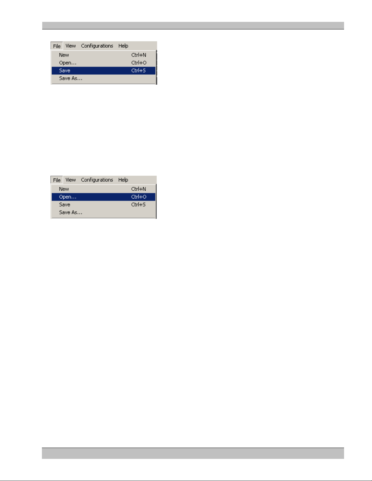
HD Player Chapter: 10 Configuration Files
Or, press Ctrl-S on the keyboard.
Loading a configuration file
A different configuration can be loaded into the HD Player using the load command.
To load a configuration file:
Click File/Open from the main menu
Or press Ctrl-O on the keyboard.
65 Rev. 6.8
Page 66

HD Player Chapter 11: Remote Control Configuration
Chapter 11: Remote Control Configuration
Two specific components are required for the remote control of the HD Player: a physical link and a protocol.
These are analogous to a telephone conversation between two people - the telephone being the physical link and
the protocol the language used for the conversation.
The HD Player utilizes two types of physical links, RS232 serial, or Ethernet using TCP/IP.
A number of different protocols are available for interface with standard control systems.
In order to use the Player for remote control a “Method” needs to be created. This provides the link between
physical medium, protocol, and video channels.
Methods are created using the “Remote Control Methods wizard”. This can be reached from the configuration
menu as illustrated below.
• Click on Configurations/Re m ot e Control Configurat io ns in the main menu to display the Remote
Control Methods wizard described in the following section.
The Remote Control Methods dialog
The initial Remote Control Methods display shows a list of methods that have been defined so far. The number of
methods allowed is unlimited and can use any combination of RS232 and TCP/IP.
To create a new Method
Click the New button located to the right of the dialog. This will invoke the Method Type page of the Remote
Control Wizard. The wizard follows the format commonly found in Windows based software, where a series of
screens appear requiring information to be entered. When you have entered the details required in a screen, use the
“Next” button to move on to the next page. The Back button can be used at any time to step to the previous page.
66 Rev. 6.8
Page 67

HD Player Chapter 11: Remote Control Configuration
Click here
To Edit Method settings
Click the Method name and then click the now active Edit button. This will produce the remote method wizard,
from where the required settings can be changed.
To Delete a Method
Click the Method name then click the now active Delete button. A confirmation prompt will appear, to prevent
accidental deletion.
Click the Delete All button to remove all methods from the table. Care should be taken using this option, since it
cannot be undone.
The following sections describe each page of the wizard.
The Remote Control Wizard - Method Type dialog
The first screen in the wizard requires two pieces of information, the method name and the physical connection
type. Every method must have a unique name, which is used to identify the method in the Log window. There are
currently two physical connection types, Serial (RS232) and TCP/IP.
Click on the list to select either Serial or TCP/IP
Click Next to advance to either the Serial Control Parameters page or the TCP/IP Configuration page.
Information for the Serial Control Parameters is given next, followed by information for TCP/IP Configuration.
67 Rev. 6.8
Page 68

HD Player Chapter 11: Remote Control Configuration
The Remote Control Wizard - Serial Control Parameters (RS232) page
This page of the wizard will appear if Serial (RS232) was selected from the “Method Type” page described above.
The page is used to select the parameters for the serial port, from the following allowable settings.
Baud 1200, 2400, 4800, 9600, 19200, 57600, 115200.
Parity Odd, Even or None.
Stop bits 1 or 2 stop bits.
To modify the Serial Control Parameters:
• Click the arrow buttons adjacent to the appropriate boxes and select the necessary settings from the
options listed.
• Click the Next button to accept the settings and advance to the Choose Protocol page
Remote Control Wizard Protocol pa ge
Use this page to select the protocol necessary for a specific Remote control Method. A detailed description of the
available protocols is provided in the “Protocol Reference” section later in this manual.
68 Rev. 6.8
Page 69

HD Player Chapter 11: Remote Control Configuration
Click on the list to select either Protocol.
Click Next to advance
Click Finish to end. This will return you to the Remote Control Methods.
69 Rev. 6.8
Page 70

HD Player Chapter 11: Remote Control Configuration
Enter port
The Remote Control Methods wizard TCP/IP page
The following window results after selecting the TCP/IP option and clicking Next on the “Method Type” page of
the Remote Control Wizard. There is only one parameter required, the TCP/IP port to use for the connection. It is
usually safe to select ports above the value 2000, although any number can be used in a closed installation.
number 4000
1. Enter the port number in the window
NOTE: When using ESCAN for control, set Port to 4000 and select MSVPP Protocol.
2. Click Next to advance to the Protocol page.
3. Choose a protocol for this channel from the drop-down list:
MSVPP
ES4000 H-Type Parser v1.02
Telnet Parser v1.06
4. Click on the list to select a Protocol.
5. Click Next to advance
6. Click Finish to end. This will return you to the Remote Control Methods.
70 Rev. 6.8
Page 71

HD Player Chapter 12: Remote Control Protocols
PIN1 Data carrier detect
PIN2 Receive data
PIN3 Transmit data
PIN4 Data Terminal ready
PIN5 Ground
PIN6 Data set ready
PIN7 Request to send
PIN8 Clear to send
PIN9 Ring Indicator
(DCD)
(RXD)
(TXD)
(DTR)
(SG)
(DSR)
(RTS)
(CTS)
(RI)
9 WAY D TYPE PLUG
(FRONT VIEW)
1 5
6 9
Pin No
Signal
Pin No
Signal
1
Tx+
5
No connect
2
Tx-
6
Rx-
3
Rx+
7
No connect
4
No connect
8
No connect
Chapter 12: Remote Control Protocols
The HD Player facilitates remote control with Serial and LAN connectors located at the rear. We recommend that
you use commercially manufactured connecting cables. Should you wish to make your own cables, the HD
Player’s control pinouts are given below.
Serial Port Pinout
Figure 6. Serial Port Pin Functions
RJ45 Ethernet
This is a 100 Base T connection that supports the TCP/IP protocol.
RJ45 Pinout
Text Command Protocol (Telnet Protocol)
The Text Command Protocol is a simple ASCII text based control method primarily designed for easy control
through a TCP/IP connection or a serial port.
The simplest way to test and experiment with the protocol is to connect the Electrosonic HD Player to a remote
computer running the Telnet program (supplied with all Windows™ operating systems), and to enter commands
using the remote computer’s keyboard.
71 Rev. 6.8
Page 72

HD Player Chapter 12: Remote Control Protocols
To Run Telnet
1. Click the Windows Start icon on your desktop
2. Select Run. The window below opens:
3. Enter “Telnet” in the text box and click the OK button
The Telnet window appears:
Enter your commands using the Command Structure shown in the following section.
NOTE: The HD Player currently supports a single HD output. To allow for future expansion and to provide
compatibility across all Electrosonic Player products, the Telnet protocol requires a channel number. This
parameter should be set to 1 in the single channel version unless it has been changed using the Base Channel
Number setting in the Channel Properties window.
Command Structure
The basic structure for a telnet command is as follows:
KeyWord <channel no> <parameter> <terminator>
The channel no (channel number) is mandatory. For the HD Player use 1 unless you have changed the Base
Channel Number setting in the Channel Properties window (Refer to Chapter 5: HD Player Configuration).
The parameter is only used on some commands. For instance, it could be a chapter number.
The terminator can be either a Carriage Return, a Carriage Return & Line Feed, or a NULL (0x00).
Commands are not case sensitive.
NOTE: In the following Command Reference Chapter = MPEG File
72 Rev. 6.8
Page 73

HD Player Chapter 12: Remote Control Protocols
Player Type
Description
MS9100HD
9100 series based HD players
MS9200HD
9200 series based HD players.
Mode
Description
Composite
Standard definition composite video output
YC
Standard definition YC video output
RGBHV
RGBHV Component video output
YprPb
YprPb component video output
RGsB
Component Sync On Green
Command Reference
Configuration Com m ands
GetPlayerType
This command requests the type of player. The player will respond with:
PlayerType <string1> <number>
Where: String1 = The player type from the player type list below.
Number = software version.
The software version will be a numerically increasing version number
GetChannelCount
This command requests the number of channels present on the player. The player will respond with:
ChannelCount <number>
SetOutputMode <channel> <string>
This command is used to set the output mode for the player.
<String> is taken from the output mode table.
The Player will respond with:
OK or ERROR
GetOutputMode <channel>
This command is used to get the current output mode for the player. The Player will respond with:
OutputMode <string>
String is taken from the Output mode table.
73 Rev. 6.8
Page 74

HD Player Chapter 12: Remote Control Protocols
Resolution
Description
Freq.
Freq.
Freq.
Freq.
Freq.
Freq.
Video
Standard definition video
720x480
X X
X
720x567
X
960x720
X
1024x768
X
1280x720
X X X
X
1280x1024
X
X
1440x1080
X
1600x1200
X X
1920x1080
X X X X X
X
GetOutputResolution <channel>
This command is used to retrieve the current output resolution and frequency for the player.
The Player will respond with:
OutputResolution <channel> <string> <number>
Where string contains an entry from the Output resolution table and number contains an entry from the
frequency table (below). Example: outputresolution 1 1920 1080 i 59
SetOutputResolution <cha nnel > <stri ng> < num ber>
This command is used to set the output resolution and frequency for the player.
<String> is taken from the resolution table and must be a valid return option from the GetOutputResolution
command.
<Number> is taken from the frequency table and must be a valid frequency for the output resolution.
The resolutions (except video) must have either an I or P appended to the name to indicate Interlace or
Progressive.
Example: setoutputresolution 1 1920 1080 i 59 (string = resolution; from the table) (number = frequency; from
the table)
The Player will respond with:
OK or ERROR
23
24
48
50
59
60
74 Rev. 6.8
Page 75

HD Player Chapter 12: Remote Control Protocols
Media Managemen t C om m an ds
GetMediaTree
This command is used to retrieve the media storage tree from the player. This command doesn’t return a file
listing, only the tree structure.
The player responds with a series of path commands with the following structure. The tree is terminated with an
empty MediaBranch command:
MediaBranch <channel list> <mediapath>
The <channel list> specifies the channels that can use the media. <mediapath> specifies the name of the
branch in a tree format using a Unix style format. The control system will not interpret the string but will
pass it back to the player when creating playlists.
The GetMediaTree command essentially performs a left hand depth first traverse of the media tree.
The following exchange shows an example response from the player.
MediaBranch 1,2,3,4 “/e”
MediaBranch 1,2,3,4 “/e/exhibit”
MediaBranch 1,2,3,4 “/e/exhibit/mainshow”
MediaBranch 1,2,3,4 “/e/exhibit/ gri ds”
MediaBranch 5,6,7,8 “/f”
MediaBranch 5,6,7,8 “/f/show version 1”
MediaBranch 5,6,7,8 “/f/show version 2”
MediaBranch
In this example the player wraps two hard drives (e and f) into a Unix style tree by simply using the letter as the
root of the tree.
GetClips <mediapath>
This command lists the clips available in a MediaBranch passed in the <string> parameter.
The player responds with a series of clip commands with the following structure. The clip list is terminated with
an empty Clip command.
Clip <mediapath> <clip>
Where <string1> contains a branch returned by GetMediaTree, and <string2> is the name of a clip.
The following exchange shows an example response from the player.
Control: GetClips “/e/exhibits”
Player: Clip “/e/exhibits” “Main screen L.mpg”
Player: Clip “/e/exhibits” “Main screen R.mpg”
Player: Clip “/e/exhibits” “Main screen C.mpg”
Player: Clip
75 Rev. 6.8
Page 76

HD Player Chapter 12: Remote Control Protocols
Playlist Commands
ClearPlaylist <string>
This command clears all the entries from the playlist identified by <string>.
The Player will respond with:
OK or ERROR
ListAllPlaylists
Returns a list of all the playlists stored in the server.
The player responds with a list of Playlist commands as follows:
laylist <string1>
Where <string1> identifies a playlist. The list is terminated with an empty Playlist message.
Example:
Playlist “Left Screen”
Playlist “Right Screen”
Playlist
AddPlaylist <string1> <mediapath> <clip>
Adds a clip identified by <clip> located in the media path identified by <mediapath> to the playlist identified by
<string1>.
The Player will respond with:
OK or ERROR
Example:
AddPlaylist “Left Screen” “/e/exhibits” “Main screen intro.mpg”
AddPlaylist “Left Screen” “/e/exhibits” “Main screen L.mpg”
The control system doesn’t need to terminate the playlist creation commands since the functionality is implied in
the command.
LoadPlaylist <Channel list> <string1>
Loads the playlist identified by <string1> onto the channels specified in <Channel list>. The clips specified in the
playlist must be available to all channels identified in <Channel list>.
The Player will respond with:
OK or ERROR
76 Rev. 6.8
Page 77

HD Player Chapter 12: Remote Control Protocols
ListPlaylist <string1>
Returns a list of the clips contained in the playlist identified by <string1>.
The player responds with a list of PlaylistEntry commands as follow:
PlaylistEntry <string1> <mediapath> <clip>
Where <string1> identifies a playlist, <string3> identifies a media clip located in the media path
identified by <string2>.
The list is terminated with an empty PlaylistEntry message.
Example:
PlaylistEntry “Left Screen” “/e/exhibits” “Main screen intro.mpg”
PlaylistEntry “Left Screen” “/e/exhibits” “Main screen L.mpg”
PlaylistEntry
Switchplaylist <Channel list> <string>
The player will perform a seamless switch to another playlist at the end of the currently playing clip.
The Player will respond with
OK or ERROR
Example:
Switchplaylist 1 “Playlistname”
Playrange <Channel list> <start chapter> < end chapter>
Sets the start and end chapters for a Playlist on the specified channel. This command will also pre-load the start
chapter in preparation for the Playlist command.
The Playrange command requires an amount of time to complete, because of some initialization that must occur
when a new file is selected. The status commands can be used to poll the player to find out when the playrange
command completes. If the HD Player is required to simply repeat-play the file (in a theater for example) it is
more efficient to use the “loop” command (see Loopon below).
The Player will respond with:
OK or ERROR
Fastseek <Channel list> <start chapter> <end chapter>
Facilitates cueing a file (or files) across multiple players in a synchronized system.
The Player will respond with:
OK “channel ‘X’ cued” or ERROR
Adjustrange <Channel list> <start chapter> < end chapter>
Adjusts the start and end chapters for the current playlist on the specified channel. This command does not cue
files. It is used to dynamically adjust the play order of files in a playlist. This interface is indented for backwards
compatibility.
77 Rev. 6.8
Page 78

HD Player Chapter 12: Remote Control Protocols
The Player will respond with:
OK or ERROR
78 Rev. 6.8
Page 79

HD Player Chapter 12: Remote Control Protocols
Replace <Channel list> <source> <destination>
This command is used to replace a clip in the playlist. It can be used to achieve dynamic adjustment of seamless
playback playlists.
This interface is indented for backwards compatibility.
The Player will respond with:
OK or ERROR
Playback Comman ds
Play <Channel list>
Play the currently loaded playlist
The Player will respond with:
OK “channel ‘X’ playing” or ERROR
Stop <Channel list>
Stops the currently playing file and turn video off.
The Player will respond with:
OK “channel ‘X’ paused” or ERROR
Pause <Channel list>
Pauses the currently playing file.
The Player will respond with:
OK “channel ‘X’ paused” or ERROR
Seek <Channel list> <frameno>
Seek to a position in the file. The position is specified as a frameno.
The Player will respond with:
OK “channel ‘X’ cued”/”channel ‘’ playing” or ERROR
Seek <Channel list> <timecode>
Seek to a position in the file. The position is specified as a timecode.
The Player will respond with:
OK “channel ‘X’ playing” or ERROR
79 Rev. 6.8
Page 80

HD Player Chapter 12: Remote Control Protocols
Audioon <Channel list>
Turn audio on for the requested channel.
The Player will respond with:
OK or ERROR
Audiooff <Channel list>
Mute the audio on the requested channel.
The Player will respond with:
OK or ERROR
Videoon <Channel list>
Turn on video for the requested channel.
The Player will respond with:
OK or ERROR
Videooff <Channel list>
Turn off (“Mute”) video on the required channel.
The Player will respond with:
OK or ERROR
Videobars <Channel list>
Turn on video color bar output for the requested channel.
The Player will respond with
OK or ERROR
Loopon <Channel list>
Enable the Auto repeat mode. This will cause the channel to loop (auto-repeat) at the end of the selected files in
the playlist.
The Player will respond with:
OK or ERROR
80 Rev. 6.8
Page 81

HD Player Chapter 12: Remote Control Protocols
Loopoff <Channel list>
Turn off the loop flag for the requested channel.
The Player will respond with:
OK or ERROR
System/Status Commands
Shutdown
Shut the Player system down.
The player doesn’t send a response to this command.
Reboot
Reboot the HD Player.
The player doesn’t send a response to this command.
Getstate <Channel list>
Request the status of certain parameters for a specific player (Channel)
The Player will respond with:
Statetc 1 “00:00:00:00” (“current timecode”)
Statefile 1 “clip” “
Stateplay 1 “status”
(current clip”)
(“playing”, “paused”, “stopped”)
Timecode Commands
Tcgenerate <Channel list> <timecode>
Turns the timecode generator on and sends the timecode hh:mm:ss:ff out as a jam sync.
The Player will respond with:
OK or ERROR
Tcreceive <Channel list>
Sets the player into timecode receive mode.
The Player will respond with:
OK or ERROR
Tcreceiveloop <Channel list>
Sets the player into timecode receive mode and loop the input timecode to the output.
81 Rev. 6.8
Page 82

HD Player Chapter 12: Remote Control Protocols
The Player will respond with:
OK or ERROR
Tcplayat <Channel list> <timecode>
Sets the timecode playat time
The Player will respond with:
OK or ERROR
Tcstopat <Channel list> <timecode>
Sets the timecode stopat time
The Player will respond with:
OK or ERROR
Tcstart <Channel list>
Starts the timecode running (assumes the player is in Generate mode – refer to “The Timecode configuration
dialog” section of Chapter 6: Timecode)
The Player will respond with:
OK or ERROR
Miscellaneous Commands – (Telnet Protocol)
Playfiles <Channel> <start chapter> <end chapter>
Load and play a range of files
Playlist <Channel>
Begins playback of the selected chapters. This command should normally follow a Playrange command.
Play <Channel>
Play the currently loaded file.
[When a file is playing the HD player will return this command:
Channel x Playing <cr> <lf> (where x is the base channel set in the channel properties)
.]
[When a file has played the HD Player will return this command:
Channel x Playlist Complete <cr> <lf> (where x is the base channel set in the channel properties)
.]
Note: The Play and Playlist commands are identical in the HD Player. Both are maintained for compatibility with
other Electrosonic Player products.
Seek <channel> <frameno>
Seek to a position in the file. Note: This will seek to the next closest index point (i.e. I frame) to the frameno
Add <Channel> <FileName>
Adds a file to the playlist of the requested channel.
Clear <Channel>
82 Rev. 6.8
Page 83

HD Player Chapter 12: Remote Control Protocols
Clears all files from the playlist.
List <Channel>
Returns a list of the files loaded into the current playlist.
83 Rev. 6.8
Page 84

HD Player Chapter 12: Remote Control Protocols
Playrange 1 0 0 <cr>
This command pre-loads channel 1 with the first entry in the
Play 1 <cr>
This command plays the file selected on channel 1 by the
^A H Frame No
^B
Player Commands
^W
^C
Examples
Use the following sequence of commands to set up and play an entry from the Playlist.
playlist.
command above.
ES 4000
The ES 4000 Protocol is a proprietary protocol developed by Electrosonic for integrated control of their entire
product range, covering ESLINX, PICBLOC, IMAGESTAR etc. A subset of this protocol, called the H type
message, was designed to communicate with Electrosonic devices that provide control of source machines such as
Laserdisks. The HD Player recognizes a subset of the H Type protocol. This provides the simplest way for the HD
Player to be integrated into shows programmed with Easy and C- through (by Electrosonic).
The protocol is structured as follows.
These fields are as follows.
^A – Start of message marker. (01 Hex)
This single byte value indicates the start of a message.
H – message type indicator (48 Hex)
This single byte value indicates the ES4000 message type
FrameNo – Chapter/frame No
This field is a six digit numeric ASCII field that is used for the search, chapter start, and chapter stop commands.
^B – End of header marker. (02 Hex)
This single byte value marks the end of the header and start of the player commands.
Player Commands
This field specifies a command for each of 12 possible channels provided by the protocol (this allows multiple
Players to be controlled from a single command). 2 ASCII digits represent each command, therefore the Player
Command field can contain up to 24bytes. (Note the HD Player will only process commands up to the ^W marker
so that if you only wish to control channels 1- 4 then only 8 bytes are required (2 bytes for 4 players).
The ES400 setup options for the HD Player allow the user to select which channel, out of the 12 possible, should
be monitored.
^W –End of command block. (17 Hex)
This single byte value indicates the end of the player commands block.
^C– End of message marker. (03 Hex)
This single byte value indicates the end of the message
84 Rev. 6.8
Page 85

HD Player Chapter 12: Remote Control Protocols
Command
Action
C6
Play
C5
Pause
E4
Video Off
E3
Video On
E5
Chapter Mode (FrameNo = first file to play in playlist)
E6
Frame Mode
83
Audio On
84
Audio Off
A2
Set stop point for play list. ( FrameNo = last file to play in playlist.)
Available Player Commands
The following table illustrates the commands that are supported by the HD Player.
To use the ES400 protocol to control the HD Player, the following steps should be performed.
Set up a Playlist containing the files to be used in the installation.
Send a chapter start with the FrameNo field set to the first chapter to play in the Playlist.
Send a stop point with the FrameNo Field set to the last chapter to play in the Playlist.
Send a Play command to play the files.
85 Rev. 6.8
Page 86

HD Player Chapter 13: Video Outputs
DECODER
CARD,
DIGITAL
(MS9200)
EXTENDER
CARD,
(MS9200)
HD-1
HDSDI
HD-2
OUT
IN
ES GENLOCK
CVBS
SPDIF
IN
OUT
TIMECODE
DECODER
CARD,
ANALOG
(MS9100)
TIME CODE
IN/OUT
HD
CVBS
SPDIF
Chapter 13: Video Outputs
The Electrosonic HD Player has three video output options (see below), depending upon the Color Space selected
and which type of HD Player is in use.
In the RGB color space two analog outputs are available simultaneously with the MS9200P. A single analog
output is available in the case of the MS9100P and the MS9100D.
In the YPrPb color space the HDSDI output is also available (MS9200P only).
The PCI HD Decoder Card Interfaces
The following figure shows the PCI Decoder card interface:
86 Rev. 6.8
Primary Output: MS9200P/MS9100P/MS9100D
This output provides an analog RGBHV or YPrPb output on a 15pin D type connector.
The output signal levels are:
• 1V p–p RGB and YPrPb
• 3.3V p-p HSync and Vsync
Secondary Outpu t: MS 92 0 0P
This output provides an analog RGBHV or YPrPb output on a 15pin D type connector. This output supports the
option of horizontal and vertical Soft Edging.
Page 87

HD Player Chapter 13: Video Outputs
• 1V p–p RGB and YprPb
• 3.3V p-p HSync and Vsync
• Horizontal and Vertical Edge blending 1 – 255 pixels/lines
HDSDI: MS9200P
This is a digital output conforming to the SMPTE292M specification. It is output on the BNC connector.
Currently it supports 1920 x 1080 and 1280 x 720 resolutions in YPrPb color space only. This output can also be
soft edged.
• Horizontal and Vertical Edge Blending 1 – 255 pixels / lines
87 Rev. 6.8
Page 88

Page 89

HD Player Chapter 14: Application Notes
Chapter 14: Appli c ation Notes
The following sections contain some application specific notes to help the system designer and installer use the
Electrosonic HD Player in 3D or multi-channel configurations.
Synchronized playback
The Electrosonic HD Player has been designed to support applications requiring multiple HD sources. Typical
uses of this feature include, High Resolution 3D displays or multi-source shows with soft edging.
There are two control conditions that need to be met before a system can playback synchronously. Firstly the
players must start at the same time and secondly they must playback locked together in a condition known as
Genlock. These concepts are discussed later in this chapter.
Content Preparation
The first requirement for a multi-source system is that the content being displayed is “correct” on all Players.
There are certain constraints that MPEG streams must operate within to ensure successful synchronization. The
most important of these is that the first frame of the stream is an I frame and follows a Group of Pictures header
(for a discussion of these terms please refer to the MPEG appendix). This is easy to implement when using a
software encoder, but may prove difficult if using an encoder linked to a tape machine. Most of the currently
available “Broadcast quality” encoders are designed to stream to an uplink transmitter and do not usually have the
ability to frame accurately encode, or record to a storage medium such as disk.
Since most systems will use a Genlock signal that will be either 29.97Hz or 25Hz it is necessary that the frame
rate of the content also be one of these frequencies.
Genlock
The genlock features in the HD Player can be used to ensure the output rasters from the multiple units stay locked
together. This ensures that once the units begin playing the output video will stay synchronized. In a closed system
it is only necessary to designate one Player as the Genlock Master and the rest as Genlock Slaves. Genlock will
keep the units playing in sync. relative to each other but they also need to start at the same time, see the following
sections for information on timecode triggers.
Playing in Sync. with Timecode
The only guaranteed way to trigger a multi-channel show is to use the timecode input. The timecode can come
from an external generator or one of the HD Players can be used to generate the timing reference. The timecode
‘Start’ point is set on the Master player a few seconds in advance of the ‘Play At’ timecode that is set identically
on both Master and Slave. The separate timecode section of this manual contains a detailed description of the
timecode capabilities and explains how to set up a timecode trigger on both the Master and the Slave(s).
The timecode trigger is set up using a “cue” or “play range” command from an external control system before the
timecode feed starts counting. See Cueing and Playing with Serial Control below.
Cueing and Playing with Serial control
Before a system will ‘trigger’ from a timecode point the Players must be ‘Cued’ and sent a ‘Play’ command. On
receipt of the ‘Play’ command the Master Player will start to generate timecode. When the ‘Play At’ timecode
point is reached all players will start.
89 Rev. 6.8
Page 90

HD Player Chapter 14: Application Notes
A simple way to set up a system using this method is to “common” the RS232 receive lines on all the HD Players
to the transmit signal of the RS232 port on the show control system.
After the Play command is received the Players will wait for the timecode trigger to commence playback in sync.
90 Rev. 6.8
Page 91

HD Player Chapter 14: Application Notes
Example: A Two Player System (two-channels)
The example system utilizes two MS9200 HD Players, Timecode, Genlock and a show control computer running
ESCAN (or other control software). Such a two-channel system could be used in a 3D “HD Experience”.
The following illustration shows the system hook-up when utilizing TCP/IP remote control:
Ensure that the remote control communication method for the system is correctly connected and functioning. For
more information on setting up communications protocols refer to: Chapter 11-Rem ote Control Confi gurat ion,
Chapter 12-Remote Control Protocols, and Appendix A-TCP/IP Communications.
HD Player #1 functions as Master to generate a triggering timecode and Genlock signal for the entire system.
Time code and Genlock are fed from their respective outputs on the Master to the appropriate inputs on the Slave
unit (HD Player #2).
For simplicity, in this example we are using a single MPEG chapter (file) to be played concurrently by each
player.
Use the control software, running on the Show Control Computer to generate a control sequence for the “show”.
Refer to the Command Reference section in Chapter12, Remote Control protocols for specific command syntax.
The requirements for the sequence are:
• Cue the players (Fastseek or Playrange commands)
• Designate Device 1 as Master timecode generator for the system (Tcgenerate)
91 Rev. 6.8
Page 92

HD Player Chapter 14: Application Notes
Device 1 “Master”
Device 2 “Slave”
Playrange 1 0 0 <cr>
Playrange 1 0 0 <cr>
Tcgenerate 1 <cr>
Tcreceive 1 <cr>
Tcplayat 1 01:00:00:00 <cr>
Tcplayat 1 01:00:00:00 <cr>
Tcstart 1 00:59:55:05 <cr>
Device 1 “Master”
Device 2 “Slave”
Playrange 1 0 0 <cr>
Playrange 2 0 0 <cr>
Tcgen 1 <cr>
Tcreceive 2 <cr>
Tcplayat 1 01:00:00:00 <cr>
Tcplayat 2 01:00:00:00 <cr>
Tcstart 1 00:59:55:05 <cr>
• Designate Device 2 as “Slave” (Tcreceive)
• Set both devices to begin playing at a specific time (Tcplayat)
• Start the sequence (Tcstart)
TCP/IP
Command sequence to play file 0 on both players at 01:00:00:00.
NOTE: The Channel numbers (Base Channel) are the same for both devices as the TCP/IP configuration
determines their “addresses”. Refer to Chapter 5, HD Player Configuration for more information on how to set
the Base channel.
RS232
NOTE: The Channel numbers are different for each HD Player. Refer to Chapter 5, HD Player Configuration for
how to set the Base channel.
92 Rev. 6.8
Page 93

HD Player Chapter 14: Application Notes
93 Rev. 6.8
Page 94

HD Player Chapter 14: Application Notes
The following diagram illustrates a Genlocked system and how it would be connected.
This system represents a three-channel display. The top HD Player is used to generate a triggering timecode for
the entire system. This timecode is looped through the middle unit, using the loop through mode, and finally sent
to the input of the third unit. The HD Players are synchronized to an external genlock source, in this case a
standard video black and burst generator.
94 Rev. 6.8
Page 95

HD Player Appendix A: TCP/IP Communications
Appendix A: TCP/IP Communications
An Introductory Note
A full explanation of Ethernet communication is beyond the scope of this user guide. However, the following
details should provide enough information to understand the basic concepts.
Ethernet Communication
The HD Player can be controlled via RS-232 and Ethernet connections. Most users will be familiar with RS-232
communication. Ethernet communication, while not a new development, is still a mystery to many.
Let’s compare the differences between RS-232 and Ethernet data:
RS-232
Designed for one port to connect to one device
Messages transmitted as a whole
No way to guarantee receipt of data
Maximum data transfer speeds of around 115 Kbps
Ethernet
Designed to connect many devices (called a “network”) on a single port
Messages transmitted in “packets”, as network traffic allows
Each device in the network has a unique address, ensuring that a data message goes only to the specified
device
Maximum data transfer speeds greater than 100 Mbps
Several types of Ethernet communications exist. The protocol, or language, that the HD Player uses for its
Ethernet communication is called TCP/IP (Transmission Control Protocol and Internet Protocol).
TCP/IP Addressing
Each device on a network requires a unique address to ensure that data is sent only to the device it is intended to
reach. Two methods exist for assigning an Ethernet addresses in a TCP/IP network:
1. Dynamic assignment
2. Static assignment
Dynamic Assignment
Dynamic address assignment requires the use of a DHCP (Dynamic Host Configuration Protocol) Player that
automatically assigns an address to a network device each time it connects. When the device connects, it may be
assigned an address that differs from the address it was last assigned.
95 Rev. 6.8
Page 96

HD Player Appendix A: TCP/IP Communications
Class Name
Valid Address
Range Identifier Arrangement
Class A
0.0.0.1 to 127.255.255.254
NNN.HHH.HHH.HHH
Class B
128.0.0.1 to 191.255.255.254
NNN.NNN.HHH.HHH
Class C
192.0.0.1 to 223.255.255.254
NNN.NNN.NNN.HHH
Static Assignment
Static assignment allows the user to assign an IP address to a device. Once assigned, it will always retain the
assigned address.
The following sections discuss the structure of IP addresses, and how to assign a static address to the HD Player.
The IP Address
An IP Address is a 32-bit binary number that is used to identify each device on an Ethernet network. This is
represented with four decimal numbers (each in the range 0 to 255) separated by dots, such as:
198.123.34.240.
This is called 'dotted decimal notation'.
Network and Host Identifiers
An IP Address is divided into two parts:
The “network identifier”
The “host identifier”
On a given network, each address must have the same network identifier value but have a unique host identifier.
For example, the following two IP addresses could exist on the same network:
208.132.180.40
208.132.180.55
This assumes that 208.132.180 is the network identifier, and 40 and 55 are the host identifiers.
The above examples are representative of a “Class C” network. Classes are explained in the next section.
Class Names
There are rules governing the valid numbers that can be assigned as network identifiers and host identifiers. The
valid numbers are assigned “classes”.
There are different “classes” of IP addresses that define:
The range of valid addresses
Which parts of the address are used for the network and host identifiers
The most common IP Address classes are:
Where:
NNN = Network identifier
HHH = Host identifier
96 Rev. 6.8
Page 97

HD Player Appendix A: TCP/IP Communications
Choosing IP Addresses
Two scenarios exist that will dictate the IP address assigned to your devices:
1. Connecting to an existing network
2. Establishing an independent network.
Connecting to an Existing Network
If your HD Player is connecting to an existing network, you will need to contact the network administrator and ask
that a suitable address be allocated to you.
Establishing an Independent Network
If the HD Player is to be used on an independent network, you can assign an IP address of your choice. Follow
the guidelines below for choosing your IP addresses.
On an independent network you can (theoretically) use any addresses you wish. However, it is recommended that
you use the Class C format (i.e. from 192.0.0.1 up to 223.255.255.253).
Note: the HD Player will be delivered pre-configured with a class C IP address from the 192.0.0.? family.
Remember that there are two rules for choosing IP addresses:
The network identifier must be the same for each address,
The host identifier must be unique for each address.
Applying these rules to Class C addresses, it can be seen that the first three decimal values of your IP addresses
must all be the same, while the last value is used to uniquely identify each device.
The following is an example of a valid Class C addressing scheme:
Device IP Address
ESCAN PC: 208.132.180.41
HD Player 1 208.132.180.42
HD Player 2 208.132.180.43
The following is an example of an invalid Class C addressing scheme:
Device IP Address
ESCAN PC 208.132.180.41
HD Player 1 192.157.180.42
HD Player 2 209.100.123.43
Note: These are invalid because the network identifier for each address is not the same, even though each IP
Address is unique.
One more concept must be discussed in order to properly assign an IP address; that of the Subnet Mask.
97 Rev. 6.8
Page 98

HD Player Appendix A: TCP/IP Communications
Class Name
Subnet Mask
Class A
255.0.0.0
Class B
255.255.0.0
Class C
255.255.255.0
The Subnet Mask
The Subnet Mask is another 32-bit binary number that is used to 'mask' certain bits of the IP Address. This
provides a method of extending the number of network options for a given IP Address. It works by allowing part
of the host identifier to be used as a 'subnet identifier'.
It is important that you set the correct value for the Subnet Mask. The basic values depend on the class of IP
Address being used:
Accessing the PC’s Subnet Mask and IP Address
Opening the Network Dialog Box:
The HD Player’s IP address is located in the Network dialog box, which can be accessed in the following manner:
Right-Click the Network Neighborhood desktop shortcut, and then select Properties.
Alternatively, select the Win dows™ Start button, then select Settings/Control Panel, and double-click
the Network icon.
After performing either of the previous steps, the Network dialog box will appear.
The Network Dialog Box
Accessing the IP Address:
To access the HD Player’s IP address from the Network dialog box, do the following:
1. Scroll down the list of installed network components, and click on the relevant “TCP/IP” entry.
2. After selecting the correct TCP/IP component, click the Properties button. The TCP/IP Properties dialog
box will appear, showing the TCP/IP address and the Subnet Mask.
98 Rev. 6.8
Page 99

HD Player Appendix A: TCP/IP Communications
The TCP/IP Properties Dialog Box
Assigning the HD Player IP Address and Subnet Mask
Setting the Subnet Mask
To set the Subnet Mask value:
1. Select “Specify an IP address” in the TCP/IP Properties dialog box,
2. Type the appropriate value in the Subnet Mask field.
Setting the IP Address
After setting the Subnet Mask value:
• Type the desired IP address in the IP Address field.
Saving the Subnet Mas k and IP Addr es s Values
After setting the Subnet Mask and IP address:
• Click on the “OK” button to save the values.
Note: You must now reboot the PC for the changes to take effect.
Pinging a Device
You can perform a simple test from your control computer to check that the HD Player is responding correctly.
To perform the test, you will use a command called “PING” (Packet Internet Groper).
Performing a Ping
1. Click on the Windows Start button, and from the menu choose Run.
2. In the Run dialog box, type in the following:
99 Rev. 6.8
Page 100

HD Player Appendix A: TCP/IP Communications
ping xxx.xxx.xxx.xxx -t
Where 'xxx.xxx.xxx.xxx' is the IP Address of the HD Player that you wish to test.
3. A 'DOS Window' will then open and show a series of responses as in the examples below.
4. To stop the ping command, press Ctrl + C on the keyboard.
Example 1: A successful Ping
If you have successfully 'pinged' the address 208.132.180.39, you will get the following response:
Reply from 208.132.180.39: bytes=32 time=2ms TTL=32
This response indicates that the device at the specified address is communicating correctly.
Note: The response 'time' value may vary according to network traffic.
Example 2: Unsuccessful Pings
If you are not successful pinging the address, you will get one of two messages. The message returned will
indicate the type of problem.
A message of:
• Request timed out - indicates that there has been no response from the specified address. Either the device
is not receiving data from the computer or the device is sending data. Check the data cabling, power and
setup of the affected device.
• Reply from 208.132.180.48: Destination host unreachable- indicates that you are trying to ping an
address with a different network identifier than your computer. Check the value of the PC’s IP address
and compare it to that of the device – the network identifiers (the first three sets of numbers in the IP
addresses) are mismatched.
100 Rev. 6.8
 Loading...