

Page 1
IMPORTANT:
f
g
ab dec
h
Go to www.extron.com for the complete
user guide, installation instructions, and
MPS601 Series • Setup Guide
specifications before connecting the
product to the power source.
This guide provides basic instructions for an experienced technician to install, set up, and operate the Extron Media Presentation
Switcher, MPS601. Installation and service must be performed by authorized personnel only. For additional information and
specications, see the MPS601 product page at www.extron.com.
Step 1 — Mount the MPS601
The MPS601 is housed in a half rack width, 6 inch deep, 1U high metal enclosure that can sit on a table with the provided rubber
feet or can be rack mounted. Select a suitable mounting location, then choose an appropriate mounting option.
Step 2 — Cable the Switcher
MPS 601
POWER
12V
0.5 A MAX
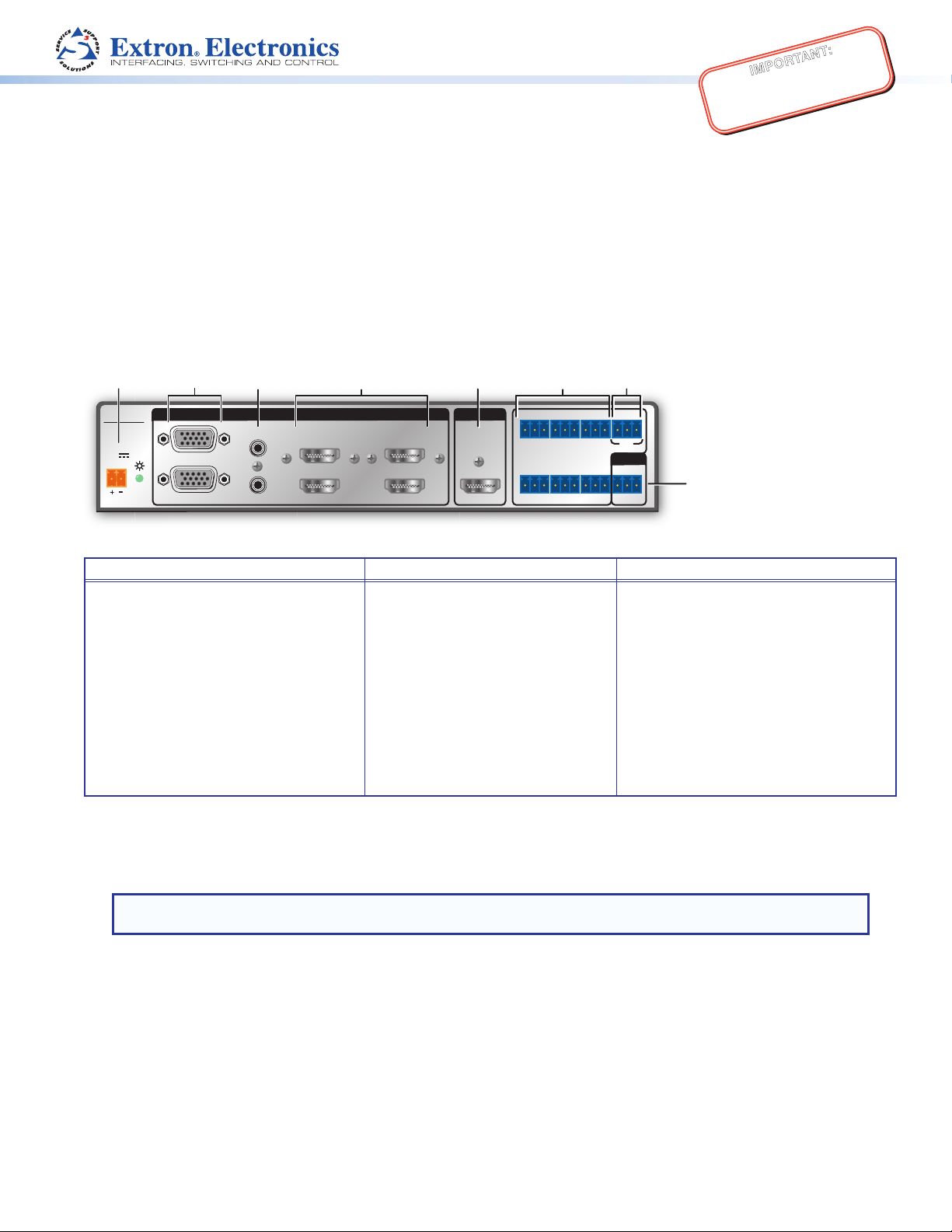
Figure 1. MPS601 Rear Panel
1
RGBHV
2
A
B
INPUTS
3
4
HDMI
5
HDMI
6
OUTPUT
HDMI
GCT TCG T+VCG
135
CONTACT IN / TALLY OUT
246
GC
TTCG TCG
REMOTE
RS-232
Tx Rx G
Power and Input Connections Output Connection Control Connections
a DC power connector — Connect the
provided 12VDC power supply.
b Two analog 15-pin HD (RGBHV)
connectors (numbered 1 and2).
c Two female 3.5 mm TRS connectors
(letter A and B on the rear panel)
corresponding to the two RGBHV
video inputs.
e HDMI video output — One female
HDMI connector
f Contact In/Tally Out —Six 3.5mm,
3-pole captive screw connectors for
input switching and tally indication
using Extron Show Me cables.
g +V Port — 3-pole 3.5mm captive
screw connector for +V output.
h Remote — 3-pole, 3.5mm captive
screw RS-232 connector.
d Four HDMI connectors for HDMI
compliant audio and video input
(numbered 3, 4, 5 and 6).
Connect Inputs
1. RGBHV video inputs — Connect analog video sources to the HD connectors (see gure 1,
signals.
). The connectors accept VGA
b
NOTE: The MPS601 digitizes the RGBHV inputs. It does not scale or convert video to a different resolution. The
output signal resolution is the same as the input resolution.
2. Analog audio inputs — By default, audio input A is tied to RGBHV input 1 and audio input B is tied to RGBHV input 2 (see
gure 1, c). Analog audio is digitized for HDMI output.
3. HDMI video inputs — Connect digital HDMI sources to these inputs using standard HDMI cables (see gure 1,
Connect Output
HDMI video output — Connect an HDMI display device using a standard HDMI cable (see gure 1, e).
d
).
1
Page 2
MPS601 • Setup Guide (Continued)
Connect Control Devices
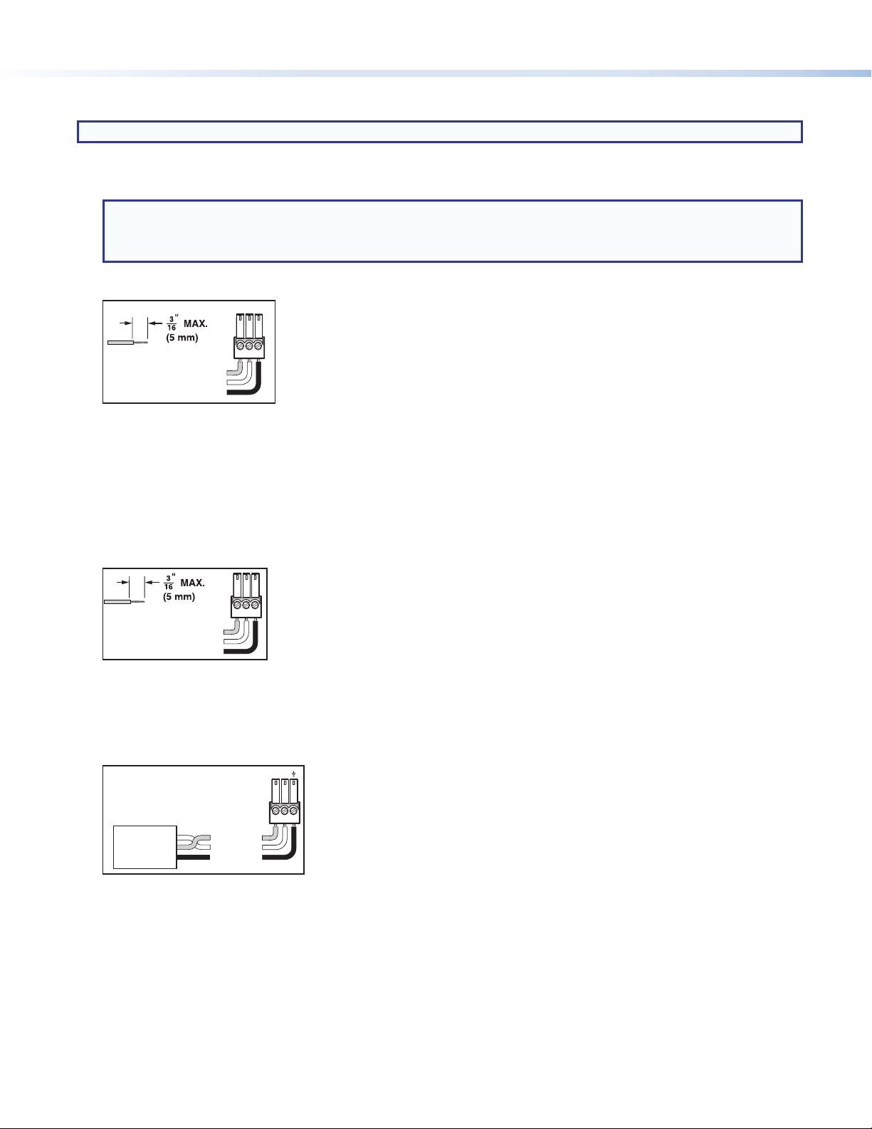
NOTE: Do not tin the leads. Tinned wires are not as secure in the connector and could be pulled out.
1. Contact In/Tally Out —When a connected contact is grounded, the corresponding input is selected (see gure 1,
). At the
f
same time, the tally output closes causing the Show Me cable LED indicator to light.
NOTE:
• For “Show Me” cables, the ground pin is optional.
• Do not connect “Show Me” cables to the +V pin of the +V Port (see below).
The six contacts are mutually exclusive so that only one input can be selected at at time.
TC G
Do not tin
the wires!
Figure 2. Contact In and Tally Out Connector Wiring
• Contact (C) – Momentary closure of this pin to ground selects the corresponding number input. Selection is triggered at
the closure (grounding) of the pin, not the opening.
• Ground (G) – Ground pin.
• Tally output (C) – Controls the LEDs on the contact closure push button. When an input is selected, the tally LED for that
input is active.
3. +V Port — All three pins constantly output +5 VDC, 200 mA total (shared between pins). The +V pins can provide power to
illuminate external tally LEDs (see gure 1, g).
Contact (NO)
Ground (G)
Tally (NO)
Do not tin
the wires!
Figure 3. +V Connector Wiring
+V
+V
+V
4. Remote RS-232 — Serial port for connection of a host computer or controller using Simple Instruction Set (SIS™) or
Windows-based control software commands (see gure 1, h). The default protocol is 9600 baud, 8 data bits, 1 stop bit, and
no parity.
An IP Link® driver allows Extron IPL and MediaLink® devices to control the MPS601 from the RS-232 remote connector.
RxTx
RS-232
Device
Transmit (Tx)
Receive (Rx)
Ground ( _ )
Figure 4. RS-232 Connector Wiring
Bidirectional
Transmit (Tx)
Receive (Rx)
Ground ( _ )
2
Page 3

Connect Power
y
)
g
Connect the provided 12VDC power supply to the rear panel captive screw connector (see gure 1, a). and plug the AC power
cord into 100-240 VAC, at 50-60 Hz.
ATTENTION:
DC Power Cord
Captive Screw
Connector
3/16"
(5 mm) Max.
Ground
+12 VDC
• Always use a power supply provided by or specied by Extron. Use
of an unauthorized power supply voids all regulatory compliance
certication and may cause damage to the supply and the end
product.
• Unless otherwise stated, the AC/DC adapters are not suitable for
use in air handling spaces or in wall cavities. The power supply is
to be located within the same vicinity as the Extron AV processing
equipment in an ordinary location, Pollution Degree 2, secured to the
equipment rack within the dedicated closet, podium, or desk.
• The installation must always be in accordance with the applicable
External
Power Suppl
AC Power Cord
Figure 5. Power Supply Wiring
(12 VDC, 1 A
provisions of National Electrical Code ANSI/NFPA 70, article 75 and
the Canadian Electrical Code part 1, section 16. The power supply
shall not be permanently xed to building structure or similar structure.
Configuring the MPS601
The MPS601 can be congured using a connected PC and the Extron Product Conguration Software or using SIS commands.
To congure the MPS601 using the Product Conguration Software, install the software (available on the Extron website,
www.extron.com) on a PC connected to the MPS601 by the rear panel remote (RS-232) port (see gure 1, h), or front panel
USB Cong port (see gure 6, b). After the installation, start the program. See the MPS601 User Guide and the Product
Configuration Software Help File for additional information.
To congure the MPS601 using SIS commands, see the MPS601 User Guide.
ab fc d e
AUTO
SWITCH
CONFIG
Figure 6. MPS601 Front Panel
1 2 3 4 5 6
INPUTS
SIGNAL
HDCP
INPUTS
12 3 45 6
MEDIA PRESENTATION SWITCHER
OUTPUT
MPS 601
Setup and Operation
a Power on all connected devices, then apply power to the MPS601. The Auto Switch LED lights when auto-input switching is
active.
b One mini type-B female USB Cong port connects to a host computer for conguring the switcher and upgrading rmware.
c Input switching. The input group has six buttons with associated green LEDs. Press an input button to switch the input to the
HDMI output. The associated LED lights. Only one of the six inputs can be selected at a time.
d Input signal LEDs. Six green LEDs indicate:
• The LEDs for RGBHV inputs 1 and 2 light when horizontal sync is detected on the input.
• The LEDs for HDMI inputs 3 to 6 light when TMDS clock activity is detected on the input.
NOTE: If a connected HDMI source is HDCP encrypted, the associated input signal LED does not light until HDCP is
authenticated.
3
Page 4

e Output signal LED. This LED lights when the HDMI output is connected to a display or sink device.
Touchpanel
f HDCP input signal LEDs (inputs 3, 4, 5, and 6). These LEDs light for the associated HDMI input when the connected source is
HDCP encrypted.
g HDCP output LED. This LED lights when the currently selected input source requires HDCP and the connected output device
(sink) is authenticated.
The MPS601 can be connected to as many as six input devices. Any of the six inputs (2 RGBHV, 4HDMI) can be routed to the
HDMI output.
NOTE: The MPS 601 does not scale or convert video. However, it does convert an analog RGB/VGA input (see figure 1, b)
to digital for digital output. The output signal resolution is the same as the input resolution.
Executive mode
Executive mode, when enabled, provides security from an accidental or unauthorized
front panel button press by locking out the input switching buttons.
The RS-232 and USB ports are always accessible regardless of the executive mode
state.
To enable or disable executive mode:
• Press and hold input 1 and input 2 for 3 seconds to toggle executive mode on or
off.
• The front panel LEDs ash twice to indicate that executive mode is enabled or
disabled.
All LEDs ash twice if a button is pressed while executive mode is enabled.
Laptop with
HDMI Output
Laptop with
HDMI Output
Flat Panel Display with Speakers
HDMI
Laptop with VGA Output
Audio
HDMI
HDMI
RGBHV
MPS 601
POWER
12V
0.5A MAX
1
RGBHV
2
A
3
HDMI
4
B
INPUTS
5
HDMI
6
Extron
MPS 601
Media Presentation
Switcher
OUTPUT
HDMI
GCT TCG T+VCG
135
CONTACT IN / TALLY OUT
246
GC
TTCG TCG
REMOTE
RS-232
Tx Rx G
PC with VGA Output
HDMI
RGBHV
Audio
Blu-ray Player
STANDBY/ON
PQLS HDMI OPEN/CLOSE FL OFF
Figure 7. MPS601 Application Diagram
RS-232
Laptop with
HDMI Output
USB
HDMI
POWER
12V
500mA
MAX
Ethernet
Extron
TLP 710TV
7" Tabletop
TouchLink
Extron
Ethernet
TCP/IP
Network
COM1
Tx Rx
LAN
INPUT
1234
Extron
IPL 250
IP Link Control
Processor
COM 2 IR
1
Tx Rx
COM 3 IR
Tx Rx
SGSG
3
SGSG
2
4
RTS CTS
RELAY
1
2
RELAY
3
4
Extron Headquarters
+800.633.9876 Inside USA/Canada Only
Extron USA - West Extron USA - East
+1.714.491.1500 +1.919.850.1000
+1.714.491.1517 FAX +1.919.850.1001 FAX
4
© 2014 Extron Electronics All rights reserved. All trademarks mentioned are the property of their respective owners. www.extron.com
Extron Europe
+800.3987.6673
Inside Europe Only
+31.33.453.4040
+31.33.453.4050 FAX
Extron Asia
+65.6383.4400
+65.6383.4664 FAX
Extron Japan
+81.3.3511.7655
+81.3.3511.7656 FAX
Extron China
+86.21.3760.1568
+86.21.3760.1566 FAX
Extron Middle East
+971.4.299.1800
+971.4.299.1880 FAX
Extron Korea
+82.2.3444.1571
+82.2.3444.1575 FAX
Extron India
1800.3070.3777
(Inside India Only)
+91.80.3055.3777
+91.80.3055.3737 FAX
68-2454-50
Rev. A 01 14
 Loading...